EP2503677A2 - Reciprocal vibration type power generator equipped with inner columnar and outer annular magnetic motion block - Google Patents
Reciprocal vibration type power generator equipped with inner columnar and outer annular magnetic motion block Download PDFInfo
- Publication number
- EP2503677A2 EP2503677A2 EP12161331A EP12161331A EP2503677A2 EP 2503677 A2 EP2503677 A2 EP 2503677A2 EP 12161331 A EP12161331 A EP 12161331A EP 12161331 A EP12161331 A EP 12161331A EP 2503677 A2 EP2503677 A2 EP 2503677A2
- Authority
- EP
- European Patent Office
- Prior art keywords
- annular
- coil set
- power generation
- motion block
- columnar
- Prior art date
- Legal status (The legal status is an assumption and is not a legal conclusion. Google has not performed a legal analysis and makes no representation as to the accuracy of the status listed.)
- Granted
Links
Images

Classifications
-
- H—ELECTRICITY
- H02—GENERATION; CONVERSION OR DISTRIBUTION OF ELECTRIC POWER
- H02K—DYNAMO-ELECTRIC MACHINES
- H02K35/00—Generators with reciprocating, oscillating or vibrating coil system, magnet, armature or other part of the magnetic circuit
- H02K35/02—Generators with reciprocating, oscillating or vibrating coil system, magnet, armature or other part of the magnetic circuit with moving magnets and stationary coil systems
-
- H—ELECTRICITY
- H02—GENERATION; CONVERSION OR DISTRIBUTION OF ELECTRIC POWER
- H02K—DYNAMO-ELECTRIC MACHINES
- H02K5/00—Casings; Enclosures; Supports
- H02K5/02—Casings or enclosures characterised by the material thereof
Definitions
- the present invention is a novel design for the axial vibration type power generator, wherein the outer end of the location where the columnar magnet passing the annular power generation coil set being installed with an outer magnetic conductive member for reducing the magnetic resistance generated while the magnetic poles at two ends of the columnar magnet passing the annular power generation coil set, the columnar magnet and the outer magnetic conductive member are jointly combined to a motion block assembly (106) for generating synchronous axial displacement so as to pass the annular power generation coil set, and enable the annular power generation coil set to generate electric power based on the Lenz's Law.
- the conventional axial vibration type power generator utilizes a round columnar magnet being axially coupled with an annular power generation coil set for performing axial vibrating displacement, so that the power generation coil set is enabled to generate electric power based on the Len's Law.
- the coupling magnetic lines of the columnar magnet and the annular power generation coil set are transmitted through air, thereby the magnetic resistance is relatively larger, and the voltage of the generated electric power is therefore lowered.
- the present invention is installed with a columnar magnet in a round columnar shape and having different magnetic poles in the axial direction, and an outer magnetic conductive member enclosing at the exterior thereof, the above two are combined to a motion block assembly (106) and coaxially adjacent disposed for structuring a magnetic path for performing the synchronous axial displacement, and the outer diameter of the columnar magnet is smaller than the inner diameter of the outer magnetic conductive member and formed with an annular gap allowing an annular power generation coil set to pass therebetween, thereby when the above two axially perform relative reciprocal axial displacing vibrations, the annular power generation coil set is enabled to generate electric power based on the Lenz's Law.
- the reciprocal vibration and power generator comprises: a housing defining a cylindrical space and including a tubular annular coil set seat extending into the cylindrical space; a power generation coil set mounted on the tubular annular coil set seat; and a motion block assembly, including a magnet, axially movable within the cylindrical space and including a centre column having mounted thereon a columnar magnet, the motion block being cup shaped with an annular side wall on which is disposed an outer magnetic conductive member, the annular side wall and the centre column of the motion block assembly forming magnet line loops with the magnet and defining an inner annular space there between within which the power generation coil may be positioned.
- the conventional axial vibration type power generator utilizes a round columnar magnet being axially coupled with an annular power generation coil set for performing axial vibrating displacement, so that the power generation coil set is enabled to generate electric power based on the Len's Law.
- the coupling magnetic lines of the columnar magnet and the annular power generation coil set are transmitted through air, thereby the magnetic resistance is relatively larger, and the voltage of the generated electric power is therefore lowered.
- the present invention is installed with a columnar magnet in a round columnar shape and having different magnetic poles in the axial direction, and an outer magnetic conductive member enclosing at the exterior thereof, the above two are combined to a motion block assembly (106) and coaxially adjacent disposed for structuring a magnetic path for performing the synchronous axial displacement, and the outer diameter of the columnar magnet is smaller than the inner diameter of the outer magnetic conductive member and formed with an annular gap allowing an annular power generation coil set to pass therebetween, thereby when the above two axially perform relative reciprocal axial displacing vibrations, the annular power generation coil set is enabled to generate electric power based on the Lenz's Law.
- the present invention is a novel design for the axial vibration type power generator, wherein the outer end of the location where the columnar magnet passing the annular power generation coil set being installed with an outer magnetic conductive member for reducing the magnetic resistance generated while the magnetic poles at two ends of the columnar magnet passing the annular power generation coil set, the columnar magnet and the outer magnetic conductive member are jointly combined to a motion block assembly (106) for generating synchronous axial displacement so as to pass the annular power generation coil set, and enable the annular power generation coil set to generate electric power based on the Lenz's Law.
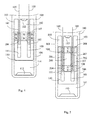
- FIG. 1 is a schematic structural view showing the interior of the annular power generation coil set (104) being coupled with the columnar magnet (107), and the exterior thereof being coupled with the outer magnetic conductive member (108), according to one embodiment of the present invention;
- FIG. 2 is a cross view of FIG. 1 ;
- FIG. 1 and FIG. 2 it mainly consists of:
- FIG. 3 is a schematic structural view showing the interior of the annular power generation coil set (104) being coupled with the columnar magnet (107), and the exterior thereof being coupled with the outer magnet (117) relatively installed in the same polarity with the columnar magnet (107), according to one embodiment of the present invention;
- FIG. 3 The cross view of FIG. 3 is the same as what is shown in FIG. 2
- FIG. 3 it mainly consists of:
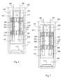
- FIG. 5 is a schematic structural view showing the present invention being composed of the annular power generation coil sets (104), (204) arranged in the multiple segment format, and the interior of the annular power generation coil sets (104), (204) being coupled with the columnar magnets (107), (207), and the exterior thereof being coupled with the outer magnetic conductive members (108), (208), according to one embodiment of the preset invention.
- FIG. 5 The cross view of FIG. 5 is the same as what is shown in FIG. 2 ;
- FIG. 5 it mainly consists of:
- FIG. 6 is a schematic structural view showing the present invention being composed of the annular power generation coil sets (104), (204) arranged in the multiple segment format, the interior of the annular power generation coil sets (104), (204) being coupled with the columnar magnets (107), (207), and the exterior thereof being coupled with the outer magnets (117), (217) arranged in the multiple segment format and relatively installed in the same polarity with the columnar magnet (107), according to one embodiment of the preset invention.
- FIG. 6 The cross view of FIG. 6 is the same as what is shown in FIG. 2
- FIG. 6 it mainly consists of:
- FIG. 7 The cross view of FIG. 7 is the same as what is shown in FIG. 2 .
- the columnar magnet (107), the columnar magnet (207), the annular power generation coil set (104), the annular power generation coil set (204), the outer magnetic conductive member (108) and the outer magnetic conductive member (208), shown in FIG. 5 are all composed of two units or more than two units;
- the columnar magnet (107), the columnar magnet (207), the annular power generation coil set (104), the annular power generation coil set (204), the outer magnet (117) and the outer magnet (217), shown in FIG. 6 and FIG. 7 are all composed of two units or more than two units;
- the columnar magnet (107), the columnar magnet (207), the outer magnetic conductive member (108) and the outer magnetic conductive member (208), shown in FIG. 5 are all composed of two units or more than two units, and the annular power generation coil set (104) is composed of one unit;
- the columnar magnet (107), the columnar magnet (207), the outer magnet (117) and the outer magnet (217), shown in FIG 6 and FIG. 7 are all composed of two units or more than two units, and the annular power generation coil set (104) is composed of one unit.
Landscapes
- Engineering & Computer Science (AREA)
- Power Engineering (AREA)
- Permanent Magnet Type Synchronous Machine (AREA)
- Reciprocating, Oscillating Or Vibrating Motors (AREA)
- General Electrical Machinery Utilizing Piezoelectricity, Electrostriction Or Magnetostriction (AREA)
Abstract
Description
- The present invention is a novel design for the axial vibration type power generator, wherein the outer end of the location where the columnar magnet passing the annular power generation coil set being installed with an outer magnetic conductive member for reducing the magnetic resistance generated while the magnetic poles at two ends of the columnar magnet passing the annular power generation coil set, the columnar magnet and the outer magnetic conductive member are jointly combined to a motion block assembly (106) for generating synchronous axial displacement so as to pass the annular power generation coil set, and enable the annular power generation coil set to generate electric power based on the Lenz's Law.
- The conventional axial vibration type power generator utilizes a round columnar magnet being axially coupled with an annular power generation coil set for performing axial vibrating displacement, so that the power generation coil set is enabled to generate electric power based on the Len's Law. However, the coupling magnetic lines of the columnar magnet and the annular power generation coil set are transmitted through air, thereby the magnetic resistance is relatively larger, and the voltage of the generated electric power is therefore lowered.
- The present invention is installed with a columnar magnet in a round columnar shape and having different magnetic poles in the axial direction, and an outer magnetic conductive member enclosing at the exterior thereof, the above two are combined to a motion block assembly (106) and coaxially adjacent disposed for structuring a magnetic path for performing the synchronous axial displacement, and the outer diameter of the columnar magnet is smaller than the inner diameter of the outer magnetic conductive member and formed with an annular gap allowing an annular power generation coil set to pass therebetween, thereby when the above two axially perform relative reciprocal axial displacing vibrations, the annular power generation coil set is enabled to generate electric power based on the Lenz's Law.
- According to another aspect of the present invention, the reciprocal vibration and power generator comprises: a housing defining a cylindrical space and including a tubular annular coil set seat extending into the cylindrical space; a power generation coil set mounted on the tubular annular coil set seat; and a motion block assembly, including a magnet, axially movable within the cylindrical space and including a centre column having mounted thereon a columnar magnet, the motion block being cup shaped with an annular side wall on which is disposed an outer magnetic conductive member, the annular side wall and the centre column of the motion block assembly forming magnet line loops with the magnet and defining an inner annular space there between within which the power generation coil may be positioned.
-
-
FIG. 1 is a schematic structural view showing the interior of the annular power generation coil set (104) being coupled with the columnar magnet (107), and the exterior thereof being coupled with the outer magnetic conductive member (108), according to one embodiment of the present invention. -
FIG. 2 is a cross view ofFIG. 1 . -
FIG. 3 is a schematic structural view showing the interior of the annular power generation coil set (104) being coupled with the columnar magnet (107), and the exterior thereof being coupled with the outer magnet (117) relatively installed in the same polarity with the columnar magnet (107), according to one embodiment of the present invention. -
FIG. 4 is a schematic structural view showing the interior of the annular power generation coil set (104) being coupled with the columnar magnet (107), and the exterior thereof being coupled with the outer magnet (117) relatively installed in different polarities to the columnar magnet (107), according to one embodiment of the present invention. -
FIG. 5 is a schematic structural view showing the present invention being composed of the annular power generation coil sets (104), (204) arranged in the multiple segment format, and the interior of the annular power generation coil sets (104), (204) being coupled with the columnar magnets (107), (207), and the exterior thereof being coupled with the outer magnetic conductive members (108), (208), according to one embodiment of the preset invention. -
FIG. 6 is a schematic structural view showing the present invention being composed of the annular power generation coil sets (104), (204) arranged in the multiple segment format, the interior of the annular power generation coil sets (104), (204) being coupled with the columnar magnets (107), (207), and the exterior thereof being coupled with the outer magnets (117), (217) arranged in the multiple segment format and relatively installed in the same polarity with the columnar magnet (107), according to one embodiment of the preset invention. -
FIG. 7 is a schematic structural view showing the present invention being composed of the annular power generation coil sets (104), (204) arranged in the multiple segment format, and the interior of the annular power generation coil sets (104), (204) being coupled with the columnar magnets (107), (207), and the exterior thereof being coupled with the outer magnets (117), (217) arranged in the multiple segment format and relatively installed in different polarities to the columnar magnet (107), according to one embodiment of the preset invention. -
- (100) : Housing
- (101) : Tubular annular coil set seat
- (102) : Round space
- (103) : Annular space
- (104) , (204) : Annular power generation coil set
- (105) : Output wire
- (106) , (206) : Motion block assembly
- (107) , (207) : Columnar magnet
- (108) , (208) : Outer magnetic conductive member
- (109) , (209) : Center column of motion block
- (110) : Cup-shaped structure of motion block
- (111) : Inner annular space of motion block
- (112) : First buffer member
- (113) : Second buffer member
- (114) : Cylindrical space inside the housing
- (117) , (217) : Outer magnet
- (201) : Tubular annular coil set partition seat
- (210) : Cup-shaped structure partition ring
- The conventional axial vibration type power generator utilizes a round columnar magnet being axially coupled with an annular power generation coil set for performing axial vibrating displacement, so that the power generation coil set is enabled to generate electric power based on the Len's Law. However, the coupling magnetic lines of the columnar magnet and the annular power generation coil set are transmitted through air, thereby the magnetic resistance is relatively larger, and the voltage of the generated electric power is therefore lowered.
- The present invention is installed with a columnar magnet in a round columnar shape and having different magnetic poles in the axial direction, and an outer magnetic conductive member enclosing at the exterior thereof, the above two are combined to a motion block assembly (106) and coaxially adjacent disposed for structuring a magnetic path for performing the synchronous axial displacement, and the outer diameter of the columnar magnet is smaller than the inner diameter of the outer magnetic conductive member and formed with an annular gap allowing an annular power generation coil set to pass therebetween, thereby when the above two axially perform relative reciprocal axial displacing vibrations, the annular power generation coil set is enabled to generate electric power based on the Lenz's Law.
- The present invention is a novel design for the axial vibration type power generator, wherein the outer end of the location where the columnar magnet passing the annular power generation coil set being installed with an outer magnetic conductive member for reducing the magnetic resistance generated while the magnetic poles at two ends of the columnar magnet passing the annular power generation coil set, the columnar magnet and the outer magnetic conductive member are jointly combined to a motion block assembly (106) for generating synchronous axial displacement so as to pass the annular power generation coil set, and enable the annular power generation coil set to generate electric power based on the Lenz's Law.
-
FIG. 1 is a schematic structural view showing the interior of the annular power generation coil set (104) being coupled with the columnar magnet (107), and the exterior thereof being coupled with the outer magnetic conductive member (108), according to one embodiment of the present invention; -
FIG. 2 is a cross view ofFIG. 1 ; - As shown in
FIG. 1 and FIG. 2 , it mainly consists of: - --Housing (100): which is constituted by a material having poor magnetic conduction and poor electric conduction, formed in a hollow cylindrical shape and one inner end inwardly extended with a tubular annular coil set seat (101) with its distal end being extended for connecting to the annular power generation coil set (104), and an annular space (103) is formed between the tubular annular coil set seat (101) and the inner hole of the housing (100), and the center of the tubular annular coil set seat (101) is formed with a round space (102), and the annular power generation coil set (104) is installed with an output wire (105) for outputting the electric power generated by the annular power generation coil set (104);
- --Motion block assembly (106): which is constituted by a material having poor magnetic conduction and poor electric conduction, and is provided with a cup-shaped structure of motion block (110) for combining with the outer magnetic conductive member (108), and the center of the cup-shaped structure of motion block (110) is provided with a center column of motion block (109) for combining with the columnar magnet (107), and the periphery of the central column of motion block (109) and the cup-shaped structure of motion block (110) form an inner annular space of motion block (111) for being sleeved and combined with the annular power generation coil set (104) and the tubular annular coil set seat (101) and allowing the mentioned two to perform relative axial displacement, and the round space (102) of the tubular annular coil set seat (101) is provided for being sleeved and combined with the columnar magnet (107) and the center column of motion block (109) and allowing the mentioned two to perform relative axial displacement;
- --A first buffer member (112) is installed between the round space (102) of the tubular annular coil set seat (101) and the inner wall of the housing (100) for serving as a buffer while the center column (109) and the columnar magnet (107) of the motion block assembly (106) and the outer magnetic conductive member (108) perform axial displacement;
- -- The mentioned columnar magnet (107) is provided for when performing the axial reciprocal vibration with the outer magnetic conductive member (108) to pass through the annular power generation coil set (104), enabling the annular power generation coil set (104) to generate a power generation effect;
- --The cylindrical space (114) inside the housing (100) is provided for being sleeved with the outer periphery of the motion block assembly (106) and allowing the relative axial displacement, and a second buffer member (113) is installed between the motion block assembly (106) and the cylindrical space (114) inside the housing (100) for serving as a buffer when the motion block assembly (106) performs the axial displacement.
-
FIG. 3 is a schematic structural view showing the interior of the annular power generation coil set (104) being coupled with the columnar magnet (107), and the exterior thereof being coupled with the outer magnet (117) relatively installed in the same polarity with the columnar magnet (107), according to one embodiment of the present invention; - The cross view of
FIG. 3 is the same as what is shown inFIG. 2 - As shown in
FIG. 3 , it mainly consists of: - --Housing (100): which is constituted by a material having poor magnetic conduction and poor electric conduction, formed in a hollow cylindrical shape and one inner end inwardly extended with a tubular annular coil set seat (101) with its distal end being extended for connecting to the annular power generation coil set (104), and an annular space (103) is formed between the tubular annular coil set seat (101) and the inner hole of the housing (100), and the center of the tubular annular coil set seat (101) is formed with a round space (102), and the annular power generation coil set (104) is installed with an output wire (105) for outputting the electric power generated by the annular power generation coil set (104);
- --Motion block assembly (106): which is constituted by a material having poor magnetic conduction and poor electric conduction, and is provided with a cup-shaped structure of motion block (110) for combining with the outer magnet (117), and the center of the cup-shaped structure of motion block (110) is provided with a center column of motion block (109) for combining with the columnar magnet (107), and the periphery of the central column of motion block (109) and the cup-shaped structure of motion block (110) form an inner annular space of motion block (111) for accommodating the annular power generation coil set (104) and the tubular annular coil set seat (101) and allowing the mentioned two to perform relative axial displacement, and the round space (102) of the tubular annular coil set seat (101) is provided for accommodating the columnar magnet (107) and the center column of motion block (109) and allowing the mentioned two to perform relative axial displacement;
- --A first buffer member (112) is installed between the round space (102) of the tubular annular coil set seat (101) and the inner wall of the housing (100) for serving as a buffer while the center column (109) and the columnar magnet (107) of the motion block and the outer magnetic conductive member (108) perform axial displacement;
- -- The mentioned columnar magnet (107) is provided for when performing the axial reciprocal vibration with the outer magnet (117) to pass through the annular power generation coil set (104), enabling the annular power generation coil set (104) to generate a power generation effect;
- --The cylindrical space (114) inside the housing (100) is provided for being sleeved with the outer periphery of the motion block assembly (106) and capable of performing the relative axial displacement, and a second buffer member (113) is installed between the motion block assembly (106) and the cylindrical space (114) inside the housing (100) for serving as a buffer when the motion block assembly (106) performs the axial displacement;
- --The magnetic pole surfaces of the columnar magnet (107) and the columnar magnet (207) relative to the annular power generation coil set (104) include in the same polarity; or as shown in
FIG. 4 ; - -- The magnetic pole surfaces of the columnar magnet (107) and the columnar magnet (207) relative to the annular power generation coil set (104) include in different polarities;
FIG. 4 is a schematic structural view showing the interior of the annular power generation coil set (104) being coupled with the columnar magnet (107), and the exterior thereof being coupled with the outer magnet (117) relatively installed in different polarities to the columnar magnet (107), according to one embodiment of the present invention; The cross view ofFIG. 4 is the same as what is shown inFIG. 2 . -
FIG. 5 is a schematic structural view showing the present invention being composed of the annular power generation coil sets (104), (204) arranged in the multiple segment format, and the interior of the annular power generation coil sets (104), (204) being coupled with the columnar magnets (107), (207), and the exterior thereof being coupled with the outer magnetic conductive members (108), (208), according to one embodiment of the preset invention. - The cross view of
FIG. 5 is the same as what is shown inFIG. 2 ; - As shown in
FIG. 5 , it mainly consists of: - --Housing (100): which is constituted by a material having poor magnetic conduction and poor electric conduction, formed in a hollow cylindrical shape and one inner end inwardly extended with a tubular annular coil set seat (101) with its distal end being extended for combining with the annular power generation coil set (104), then combined with the tubular annular coil set partition seat (201) and extendedly combined with the annular power generation coil set (204), and an annular space (103) is formed between the tubular annular coil set seat (101) and the inner hole of the housing (100), and the center of the tubular annular coil set seat (101) is formed with a round space (102), and the annular power generation coil sets (104), (204) are normal-polarity connected in parallel or in series thereby the voltage being able to accumulate during the power generation, as well as are installed with an output wire (105) for outputting the electric power generated by the annular power generation coil sets (104), (204);
- --Motion block assembly (206): which is constituted by a material having poor magnetic conduction and poor electric conduction, and is provided with a cup-shaped structure of motion block (110) for combining with the outer magnetic conductive member (108), and further combined with the cup-shaped structure partition ring (210) and extendedly combined with the outer magnetic conductive member (208), and the center of the cup-shaped structure of motion block (110) is provided with a center column of motion block (109) for combining with the columnar magnet (107), and combined with the center column of motion block (209) and further extendedly combined with the columnar magnet (207) while the periphery of the central column of motion block (109) and the cup-shaped structure of motion block (110) form an inner annular space of motion block (111) for being sleeved combined with the annular power generation coil sets (104), (204) and the tubular annular coil set partition seat (201) and the tubular annular coil set seat (101) and allowing to perform relative axial displacement, and the tubular annular coil set seat (101) and the round space (102) of the tubular annular coil set partition seat (201) is provided for being sleeved combined with the columnar magnets (107), (207) and the center column of motion block (109), (209) and allowing the mentioned components to perform relative axial displacement;
- --A first buffer member (112) is installed between the round space (102) of the tubular annular coil set seat (101) and the inner wall of the housing (100) for serving as a buffer while the center columns (109), (209) and the columnar magnets (107), (207) of the motion block and the outer magnetic conductive members (108), (208) perform axial displacement;
- --The interval of the columnar magnet (107) and the columnar magnet (207) partitioned by the center column of motion block (209), and the interval of the annular power generation coil set (104) and the annular power generation coil set (204) partitioned by the tubular annular coil set partition seat (201) enable the annular power generation coil set (104) and the annular power generation coil set (204) generate the voltage having the same phase, when the columnar magnet (107) and the columnar magnet (207) and the outer magnetic conductive member (108) and the outer magnetic conductive member (208) perform the axial reciprocal vibration to pass the annular power generation coil set (104) and the annular power generation coil set (204);
- --The cylindrical space (114) inside the housing (100) is provided for being sleeved with the outer periphery of the motion block assembly (106) and allowing to perform relative axial displacement, and a second buffer member (113) is installed between the motion block assembly (106) and the cylindrical space (114) inside the housing (100) for serving as a buffer when the motion block assembly (106) performs the axial displacement.
-
FIG. 6 is a schematic structural view showing the present invention being composed of the annular power generation coil sets (104), (204) arranged in the multiple segment format, the interior of the annular power generation coil sets (104), (204) being coupled with the columnar magnets (107), (207), and the exterior thereof being coupled with the outer magnets (117), (217) arranged in the multiple segment format and relatively installed in the same polarity with the columnar magnet (107), according to one embodiment of the preset invention. - The cross view of
FIG. 6 is the same as what is shown inFIG. 2 - As shown in
FIG. 6 , it mainly consists of: - --Housing (100): which is constituted by a material having poor magnetic conduction and poor electric conduction, formed in a hollow cylindrical shape and one inner end inwardly extended with a tubular annular coil set seat (101) with its distal end being extended for combining with the annular power generation coil set (104), then combined with the tubular annular coil set partition seat (201) and extendedly combined with the annular power generation coil set (204), and an annular space (103) is formed between the tubular annular coil set seat (101) and the inner hole of the housing (100), and the center of the tubular annular coil set seat (101) is formed with a round space (102), and the annular power generation coil sets (104), (204) are normal-polarity connected in parallel or in series thereby the voltage being able to accumulate during the power generation, as well as are installed with an output wire (105) for outputting the electric power generated by the annular power generation coil sets (104), (204);
- --Motion block assembly (206): which is constituted by a material having poor magnetic conduction and poor electric conduction, and is provided with a cup-shaped structure of motion block (110) for combining with the outer magnetic (117), and further combined with the cup-shaped structure partition ring (210) and extendedly combined with the outer magnet (217), and the center of the cup-shaped structure of motion block (110) is provided with a center column of motion block (109) for combining with the columnar magnet (107), and combined with the center column of motion block (209) and further extendedly combined with the columnar magnet (207) while the periphery of the central column of motion block (109) and the cup-shaped structure of motion block (110) form an inner annular space of motion block (111) for being sleeved combined with the annular power generation coil sets (104), (204) and the tubular annular coil set partition seat (201) and the tubular annular coil set seat (101) and allowing to perform relative axial displacement, and the tubular annular coil set seat (101) and the round space (102) of the tubular annular coil set partition seat (201) is provided for being sleeved combined with the columnar magnets (107), (207) and the center column of motion block (109), (209) and allowing the mentioned components to perform relative axial displacement;
- --A first buffer member (112) is installed between the round space (102) of the tubular annular coil set seat (101) and the inner wall of the housing (100) for serving as a buffer while the center columns (109), (209) and the columnar magnets (107), (207) of the motion block and the outer magnets (117), (217) perform axial displacement;
- --The interval of the columnar magnet (107) and the columnar magnet (207) and the outer magnet (117) and the outer magnet (217) partitioned by the center column of motion block (209), and the interval of the annular power generation coil set (104) and the annular power generation coil set (204) partitioned by the tubular annular coil set partition seat (201) enable the annular power generation coil set (104) and the annular power generation coil set (204) generate the voltage having the same phase, when the columnar magnet (107) and the columnar magnet (207) and the outer magnet (117) and the outer magnet (217) perform the axial reciprocal vibration to pass the annular power generation coil set (104) and the annular power generation coil set (204);
- --The cylindrical space (114) inside the housing (100) is provided for being sleeved with the outer periphery of the motion block assembly (106) and allowing to perform relative axial displacement, and a second buffer member (113) is installed between the motion block assembly (106) and the cylindrical space (114) inside the housing (100) for serving as a buffer when the motion block assembly (106) performs the axial displacement;
- --The magnetic pole surfaces of the columnar magnet (107) and the columnar magnet (207) relative to the annular power generation coil set (104) and the magnetic pole surfaces of the outer magnet (117) and the outer magnet (217) relative to the annular power generation coil set (204) include in the same polarity; or as shown in
FIG. 7 ; - -- The magnetic pole surfaces of the columnar magnet (107) and the columnar magnet (207) relative to the annular power generation coil set (104) and the magnetic pole surfaces of the outer magnet (117) and the outer magnet (217) relative to the annular power generation coil set (204) include in the different polarities;
FIG. 7 is a schematic structural view showing the present invention being composed of the annular power generation coil sets (104), (204) arranged in the multiple segment format, and the interior of the annular power generation coil sets (104), (204) being coupled with the columnar magnets (107), (207), and the exterior thereof being coupled with the outer magnets (117), (217) arranged in the multiple segment format and relatively installed in different polarities to the columnar magnet (107), according to one embodiment of the preset invention. - The cross view of
FIG. 7 is the same as what is shown inFIG. 2 . - The columnar magnet (107), the columnar magnet (207), the annular power generation coil set (104), the annular power generation coil set (204), the outer magnetic conductive member (108) and the outer magnetic conductive member (208), shown in
FIG. 5 , are all composed of two units or more than two units; - The columnar magnet (107), the columnar magnet (207), the annular power generation coil set (104), the annular power generation coil set (204), the outer magnet (117) and the outer magnet (217), shown in
FIG. 6 and FIG. 7 , are all composed of two units or more than two units; - The columnar magnet (107), the columnar magnet (207), the outer magnetic conductive member (108) and the outer magnetic conductive member (208), shown in
FIG. 5 , are all composed of two units or more than two units, and the annular power generation coil set (104) is composed of one unit; - The columnar magnet (107), the columnar magnet (207), the outer magnet (117) and the outer magnet (217), shown in
FIG 6 and FIG. 7 , are all composed of two units or more than two units, and the annular power generation coil set (104) is composed of one unit.
Claims (12)
- A reciprocal vibration type power generator equipped with inner columnar and outer annular magnetic motion block, wherein it is installed with a columnar magnet in a round columnar shape and having different magnetic poles in the axial direction, and an outer magnetic conductive member enclosing at the exterior thereof, the above two are combined to a motion block assembly (106) and coaxially adjacent disposed for structuring a magnetic path for performing the synchronous axial displacement, and the outer diameter of the columnar magnet is smaller than the inner diameter of the outer magnetic conductive member and formed with an annular gap allowing an annular power generation coil set to pass therebetween, thereby when the above two axially perform relative reciprocal axial displacing vibrations, the annular power generation coil set is enabled to generate electric power based on the Lenz's Law, which mainly consists of:--Housing (100): which is constituted by a material having poor magnetic conduction and poor electric conduction, formed in a hollow cylindrical shape and one inner end inwardly extended with a tubular annular coil set seat (101) with its distal end being extended for connecting to the annular power generation coil set (104), and an annular space (103) is formed between the tubular annular coil set seat (101) and the inner hole of the housing (100), and the center of the tubular annular coil set seat (101) is formed with a round space (102), and the annular power generation coil set (104) is installed with an output wire (105) for outputting the electric power generated by the annular power generation coil set (104);--Motion block assembly (106): which is constituted by a material having poor magnetic conduction and poor electric conduction, and is provided with a cup-shaped structure of motion block (110) for combining with the outer magnetic conductive member (108), and the center of the cup-shaped structure of motion block (110) is provided with a center column of motion block (109) for combining with the columnar magnet (107), and the periphery of the central column of motion block (109) and the cup-shaped structure of motion block (110) form an inner annular space of motion block (111) for accommodating the annular power generation coil set (104) and the tubular annular coil set seat (101) and allowing the mentioned two to perform relative axial displacement, and the round space (102) of the tubular annular coil set seat (101) is provided for accommodating the columnar magnet (107) and the center column of motion block (109) and allowing the mentioned two to perform relative axial displacement;--A first buffer member (112) is installed between the round space (102) of the tubular annular coil set seat (101) and the inner wall of the housing (100) for serving as a buffer while the center column (109) and the columnar magnet (107) of the motion block assembly (106) and the outer magnetic conductive member (108) perform axial displacement;-- The mentioned columnar magnet (107) is provided for when performing the axial reciprocal vibration with the outer magnetic conductive member (108) to pass through the annular power generation coil set (104), enabling the annular power generation coil set (104) to generate a power generation effect;--The cylindrical space (114) inside the housing (100) is provided for being sleeved with the outer periphery of the motion block assembly (106) and allowing the relative axial displacement, and a second buffer member (113) is installed between the motion block assembly (106) and the cylindrical space (114) inside the housing (100) for serving as a buffer when the motion block assembly (106) performs the axial displacement.
- A reciprocal vibration type power generator equipped with inner columnar and outer annular magnetic motion block as claimed in claim 1, wherein the interior of the annular power generation coil set (104) is coupled with the columnar magnet (107), and the exterior thereof is coupled with the outer magnet (117) relatively installed in the same polarity with the columnar magnet (107), which mainly consists of:--Housing (100): which is constituted by a material having poor magnetic conduction and poor electric conduction, formed in a hollow cylindrical shape and one inner end inwardly extended with a tubular annular coil set seat (101) with its distal end being extended for connecting to the annular power generation coil set (104), and an annular space (103) is formed between the tubular annular coil set seat (101) and the inner hole of the housing (100), and the center of the tubular annular coil set seat (101) is formed with a round space (102), and the annular power generation coil set (104) is installed with an output wire (105) for outputting the electric power generated by the annular power generation coil set (104);--Motion block assembly (106): which is constituted by a material having poor magnetic conduction and poor electric conduction, and is provided with a cup-shaped structure of motion block (110) for combining with the outer magnet (117), and the center of the cup-shaped structure of motion block (110) is provided with a center column of motion block (109) for combining with the columnar magnet (107), and the periphery of the central column of motion block (109) and the cup-shaped structure of motion block (110) form an inner annular space of motion block (111) for accommodating the annular power generation coil set (104) and the tubular annular coil set seat (101) and allowing the mentioned two to perform relative axial displacement, and the round space (102) of the tubular annular coil set seat (101) is provided for accommodating the columnar magnet (107) and the center column of motion block (109) and allowing the mentioned two to perform relative axial displacement;--A first buffer member (112) is installed between the round space (102) of the tubular annular coil set seat (101) and the inner wall of the housing (100) for serving as a buffer while the center column (109) and the columnar magnet (107) of the motion block and the outer magnetic conductive member (108) perform axial displacement;-- The mentioned columnar magnet (107) is provided for when performing the axial reciprocal vibration with the outer magnet (117) to pass through the annular power generation coil set (104), enabling the annular power generation coil set (104) to generate a power generation effect;--The cylindrical space (114) inside the housing (100) is provided for being sleeved with the outer periphery of the motion block assembly (106) and capable of performing the relative axial displacement, and a second buffer member (113) is installed between the motion block assembly (106) and the cylindrical space (114) inside the housing (100) for serving as a buffer when the motion block assembly (106) performs the axial displacement;--The magnetic pole surfaces of the columnar magnet (107) and the columnar magnet (207) relative to the annular power generation coil set (104) include in the same polarity.
- A reciprocal vibration type power generator equipped with inner columnar and outer annular magnetic motion block as claimed in claim 2, wherein the magnetic pole surfaces of the columnar magnet (107) and the columnar magnet (207) relative to the annular power generation coil set (104) include in different polarities.
- A reciprocal vibration type power generator equipped with inner columnar and outer annular magnetic motion block as claimed in claim 1, wherein it is further composed of the annular power generation coil sets (104), (204) arranged in the multiple segment format, and the interior of the annular power generation coil sets (104), (204) being coupled with the columnar magnets (107), (207), and the exterior thereof being coupled with the outer magnetic conductive members (108), (208), which mainly consists of:--Housing (100): which is constituted by a material having poor magnetic conduction and poor electric conduction, formed in a hollow cylindrical shape and one inner end inwardly extended with a tubular annular coil set seat (101) with its distal end being extended for combining with the annular power generation coil set (104), then combined with the tubular annular coil set partition seat (201) and extendedly combined with the annular power generation coil set (204), and an annular space (103) is formed between the tubular annular coil set seat (101) and the inner hole of the housing (100), and the center of the tubular annular coil set seat (101) is formed with a round space (102), and the annular power generation coil sets (104), (204) are normal-polarity connected in parallel or in series thereby the voltage being able to accumulate during the power generation, as well as are installed with an output wire (105) for outputting the electric power generated by the annular power generation coil sets (104), (204);--Motion block assembly (206): which is constituted by a material having poor magnetic conduction and poor electric conduction, and is provided with a cup-shaped structure of motion block (110) for combining with the outer magnetic conductive member (108), and further combined with the cup-shaped structure partition ring (210) and extendedly combined with the outer magnetic conductive member (208), and the center of the cup-shaped structure of motion block (110) is provided with a center column of motion block (109) for combining with the columnar magnet (107), and combined with the center column of motion block (209) and further extendedly combined with the columnar magnet (207) while the periphery of the central column of motion block (109) and the cup-shaped structure of motion block (110) form an inner annular space of motion block (111) for being sleeved combined with the annular power generation coil sets (104), (204) and the tubular annular coil set partition seat (201) and the tubular annular coil set seat (101) and allowing to perform relative axial displacement, and the tubular annular coil set seat (101) and the round space (102) of the tubular annular coil set partition seat (201) is provided for being sleeved combined with the columnar magnets (107), (207) and the center column of motion block (109), (209) and allowing the mentioned components to perform relative axial displacement;--A first buffer member (112) is installed between the round space (102) of the tubular annular coil set seat (101) and the inner wall of the housing (100) for serving as a buffer while the center columns (109), (209) and the columnar magnets (107), (207) of the motion block and the outer magnetic conductive members (108), (208) perform axial displacement;--The interval of the columnar magnet (107) and the columnar magnet (207) partitioned by the center column of motion block (209), and the interval of the annular power generation coil set (104) and the annular power generation coil set (204) partitioned by the tubular annular coil set partition seat (201) enable the annular power generation coil set (104) and the annular power generation coil set (204) generate the voltage having the same phase, when the columnar magnet (107) and the columnar magnet (207) and the outer magnetic conductive member (108) and the outer magnetic conductive member (208) perform the axial reciprocal vibration to pass the annular power generation coil set (104) and the annular power generation coil set (204);--The cylindrical space (114) inside the housing (100) is provided for being sleeved with the outer periphery of the motion block assembly (106) and allowing to perform relative axial displacement, and a second buffer member (113) is installed between the motion block assembly (106) and the cylindrical space (114) inside the housing (100) for serving as a buffer when the motion block assembly (106) performs the axial displacement.
- A reciprocal vibration type power generator equipped with inner columnar and outer annular magnetic motion block as claimed in claim 2, wherein it is further composed of the annular power generation coil sets (104), (204) arranged in the multiple segment format, the interior of the annular power generation coil sets (104), (204) being coupled with the columnar magnets (107), (207), and the exterior thereof being coupled with the outer magnets (117), (217) arranged in the multiple segment format and relatively installed in the same polarity with the columnar magnet (107), which mainly consists of:--Housing (100): which is constituted by a material having poor magnetic conduction and poor electric conduction, formed in a hollow cylindrical shape and one inner end inwardly extended with a tubular annular coil set seat (101) with its distal end being extended for combining with the annular power generation coil set (104), then combined with the tubular annular coil set partition seat (201) and extendedly combined with the annular power generation coil set (204), and an annular space (103) is formed between the tubular annular coil set seat (101) and the inner hole of the housing (100), and the center of the tubular annular coil set seat (101) is formed with a round space (102), and the annular power generation coil sets (104), (204) are normal-polarity connected in parallel or in series thereby the voltage being able to accumulate during the power generation, as well as are installed with an output wire (105) for outputting the electric power generated by the annular power generation coil sets (104), (204);--Motion block assembly (206): which is constituted by a material having poor magnetic conduction and poor electric conduction, and is provided with a cup-shaped structure of motion block (110) for combining with the outer magnetic (117), and further combined with the cup-shaped structure partition ring (210) and extendedly combined with the outer magnet (217), and the center of the cup-shaped structure of motion block (110) is provided with a center column of motion block (109) for combining with the columnar magnet (107), and combined with the center column of motion block (209) and further extendedly combined with the columnar magnet (207) while the periphery of the central column of motion block (109) and the cup-shaped structure of motion block (110) form an inner annular space of motion block (111) for being sleeved combined with the annular power generation coil sets (104), (204) and the tubular annular coil set partition seat (201) and the tubular annular coil set seat (101) and allowing to perform relative axial displacement, and the tubular annular coil set seat (101) and the round space (102) of the tubular annular coil set partition seat (201) is provided for being sleeved combined with the columnar magnets (107), (207) and the center column of motion block (109), (209) and allowing the mentioned components to perform relative axial displacement;--A first buffer member (112) is installed between the round space (102) of the tubular annular coil set seat (101) and the inner wall of the housing (100) for serving as a buffer while the center columns (109), (209) and the columnar magnets (107), (207) of the motion block and the outer magnets (117), (217) perform axial displacement;--The interval of the columnar magnet (107) and the columnar magnet (207) and the outer magnet (117) and the outer magnet (217) partitioned by the center column of motion block (209), and the interval of the annular power generation coil set (104) and the annular power generation coil set (204) partitioned by the tubular annular coil set partition seat (201) enable the annular power generation coil set (104) and the annular power generation coil set (204) generate the voltage having the same phase, when the columnar magnet (107) and the columnar magnet (207) and the outer magnet (117) and the outer magnet (217) perform the axial reciprocal vibration to pass the annular power generation coil set (104) and the annular power generation coil set (204);--The cylindrical space (114) inside the housing (100) is provided for being sleeved with the outer periphery of the motion block assembly (106) and allowing to perform relative axial displacement, and a second buffer member (113) is installed between the motion block assembly (106) and the cylindrical space (114) inside the housing (100) for serving as a buffer when the motion block assembly (106) performs the axial displacement;--The magnetic pole surfaces of the columnar magnet (107) and the columnar magnet (207) relative to the annular power generation coil set (104) and the magnetic pole surfaces of the outer magnet (117) and the outer magnet (217) relative to the annular power generation coil set (204) include in the same polarity.
- A reciprocal vibration type power generator equipped with inner columnar and outer annular magnetic motion block as claimed in claim 5, wherein the magnetic pole surfaces of the columnar magnet (107) and the columnar magnet (207) relative to the annular power generation coil set (104) and the magnetic pole surfaces of the outer magnet (117) and the outer magnet (217) relative to the annular power generation coil set (204) include in the different polarities.
- A reciprocal vibration type power generator equipped with inner columnar and outer annular magnetic motion block as claimed in claim 4, wherein the columnar magnet (107), the columnar magnet (207), the annular power generation coil set (104), the annular power generation coil set (204), the outer magnetic conductive member (108) and the outer magnetic conductive member (208) are all composed of two units or more than two units.
- A reciprocal vibration type power generator equipped with inner columnar and outer annular magnetic motion block as claimed in claim 5, wherein the columnar magnet (107), the columnar magnet (207), the annular power generation coil set (104), the annular power generation coil set (204), the outer magnet (117) and the outer magnet (217) are all composed of two units or more than two units.
- A reciprocal vibration type power generator equipped with inner columnar and outer annular magnetic motion block as claimed in claim 6, wherein the columnar magnet (107), the columnar magnet (207), the annular power generation coil set (104), the annular power generation coil set (204), the outer magnet (117) and the outer magnet (217) are all composed of two units or more than two units.
- A reciprocal vibration type power generator equipped with inner columnar and outer annular magnetic motion block as claimed in claim 4, wherein the columnar magnet (107), the columnar magnet (207), the outer magnetic conductive member (108) and the outer magnetic conductive member (208) are all composed of two units or more than two units, and the annular power generation coil set (104) is composed of one unit.
- A reciprocal vibration type power generator equipped with inner columnar and outer annular magnetic motion block as claimed in claim 5, wherein the columnar magnet (107), the columnar magnet (207), the outer magnet (117) and the outer magnet (217) are all composed of two units or more than two units, and the annular power generation coil set (104) is composed of one unit.
- A reciprocal vibration type power generator equipped with inner columnar and outer annular magnetic motion block as claimed in claim 6, wherein the columnar magnet (107), the columnar magnet (207), the outer magnet (117) and the outer magnet (217) are all composed of two units or more than two units, and the annular power generation coil set (104) is composed of one unit.
Applications Claiming Priority (1)
| Application Number | Priority Date | Filing Date | Title |
|---|---|---|---|
| US13/071,616 US8546964B2 (en) | 2011-03-25 | 2011-03-25 | Reciprocal vibration type power generator equipped with a moving inner columnar magnetic block surrounded by at least one coil set, and a moving outer annular magnetic block that surrounds the at least one coil set |
Publications (3)
| Publication Number | Publication Date |
|---|---|
| EP2503677A2 true EP2503677A2 (en) | 2012-09-26 |
| EP2503677A3 EP2503677A3 (en) | 2013-09-11 |
| EP2503677B1 EP2503677B1 (en) | 2014-10-15 |
Family
ID=46025337
Family Applications (1)
| Application Number | Title | Priority Date | Filing Date |
|---|---|---|---|
| EP12161331.9A Not-in-force EP2503677B1 (en) | 2011-03-25 | 2012-03-26 | Reciprocal vibration type power generator equipped with inner columnar and outer annular magnetic motion block |
Country Status (6)
| Country | Link |
|---|---|
| US (1) | US8546964B2 (en) |
| EP (1) | EP2503677B1 (en) |
| JP (1) | JP5988637B2 (en) |
| KR (2) | KR20120109404A (en) |
| CN (2) | CN102780377B (en) |
| TW (2) | TWI565196B (en) |
Cited By (2)
| Publication number | Priority date | Publication date | Assignee | Title |
|---|---|---|---|---|
| WO2015155249A3 (en) * | 2014-04-08 | 2015-12-03 | Zag Technologies (Ireland) Limited | An electromagnetic generator |
| JP2016025818A (en) * | 2014-07-24 | 2016-02-08 | 学校法人東海大学 | Electric generator |
Families Citing this family (14)
| Publication number | Priority date | Publication date | Assignee | Title |
|---|---|---|---|---|
| JP5926017B2 (en) * | 2010-09-29 | 2016-05-25 | 日亜化学工業株式会社 | Cylindrical bonded magnet |
| US8736086B2 (en) * | 2011-03-25 | 2014-05-27 | Tai-Her Yang | Reciprocal vibration type power generator equipped with inner columnar and outer annular magnetic members, a power storage device, a rectifying circuit, and a charging circuit |
| US8546964B2 (en) * | 2011-03-25 | 2013-10-01 | Tai-Her Yang | Reciprocal vibration type power generator equipped with a moving inner columnar magnetic block surrounded by at least one coil set, and a moving outer annular magnetic block that surrounds the at least one coil set |
| CN104400438B (en) * | 2014-10-23 | 2017-02-15 | 郑州金泰制罐有限公司 | Winding drum manufacturing machine |
| KR200490804Y1 (en) | 2018-05-11 | 2020-02-11 | 양대현 | Multiple Vibration Spring Generators Using Wave |
| CN111082630B (en) * | 2019-12-19 | 2021-03-30 | 歌尔股份有限公司 | Vibration device |
| US10855159B1 (en) * | 2020-02-27 | 2020-12-01 | John Sabah Gewarges | Coil regeneration device and method of use |
| US12345241B2 (en) | 2020-11-06 | 2025-07-01 | Ashot Salvaryan | Regenerative energy system using direct kinetic energy transfer to a generator |
| WO2022137981A1 (en) * | 2020-12-25 | 2022-06-30 | アルプスアルパイン株式会社 | Vibration generation device |
| WO2022137975A1 (en) * | 2020-12-25 | 2022-06-30 | アルプスアルパイン株式会社 | Vibration generating device |
| US11716003B1 (en) * | 2022-03-08 | 2023-08-01 | The United States Of America, As Represented By The Secretary Of The Navy | Electromagnetic arrays |
| US20240072625A1 (en) * | 2022-08-31 | 2024-02-29 | Nidec Corporation | Vibration motor |
| CN221305610U (en) * | 2023-11-03 | 2024-07-09 | 湖北省钻马智控科技有限公司 | Vibration motor |
| CN119231867B (en) * | 2024-11-28 | 2025-03-14 | 克瑞科技(东莞)有限公司 | Linear motor for small household appliances |
Family Cites Families (33)
| Publication number | Priority date | Publication date | Assignee | Title |
|---|---|---|---|---|
| US4454426A (en) * | 1981-08-17 | 1984-06-12 | New Process Industries, Inc. | Linear electromagnetic machine |
| JPS58165657A (en) * | 1982-03-25 | 1983-09-30 | Matsushita Electric Ind Co Ltd | brushed linear motor |
| JPS614456A (en) * | 1984-06-14 | 1986-01-10 | Mitsubishi Electric Corp | Actuator |
| JPH1132470A (en) * | 1997-07-10 | 1999-02-02 | Yamatake Honeywell Co Ltd | On-site equipment |
| US6220719B1 (en) * | 1998-02-11 | 2001-04-24 | Applied Innovative Technologies, Inc. | Renewable energy flashlight |
| US6768230B2 (en) * | 2002-02-19 | 2004-07-27 | Rockwell Scientific Licensing, Llc | Multiple magnet transducer |
| US6812583B2 (en) * | 2002-02-19 | 2004-11-02 | Rockwell Scientific Licensing, Llc | Electrical generator with ferrofluid bearings |
| US6729744B2 (en) * | 2002-03-29 | 2004-05-04 | Pat Y. Mah | Faraday flashlight |
| US6936937B2 (en) * | 2002-06-14 | 2005-08-30 | Sunyen Co., Ltd. | Linear electric generator having an improved magnet and coil structure, and method of manufacture |
| EP1378986A1 (en) * | 2002-07-02 | 2004-01-07 | Nti Ag | Constant force actuator |
| US6741151B1 (en) * | 2002-11-27 | 2004-05-25 | Levram Medical Systems, Ltd. | Moving coil linear actuator |
| US7569952B1 (en) * | 2003-04-18 | 2009-08-04 | Ferro Solutions, Inc. | High efficiency, inductive vibration energy harvester |
| JP2005094832A (en) * | 2003-09-12 | 2005-04-07 | Sony Corp | Power generator |
| US7205677B2 (en) * | 2005-05-19 | 2007-04-17 | Incelex, Llc | Automated motion provider for self powered cell phones |
| US7501834B2 (en) * | 2005-06-21 | 2009-03-10 | Custom Sensors & Technologies, Inc. | Voice coil actuator with embedded capacitive sensor for motion, position and/or acceleration detection |
| US7148583B1 (en) * | 2005-09-05 | 2006-12-12 | Jeng-Jye Shau | Electrical power generators |
| US7554224B2 (en) * | 2006-02-22 | 2009-06-30 | Perpetuum Ltd. | Electromechanical generator for converting mechanical vibrational energy into electrical energy |
| US7688036B2 (en) * | 2006-06-26 | 2010-03-30 | Battelle Energy Alliance, Llc | System and method for storing energy |
| US20080001484A1 (en) * | 2006-07-03 | 2008-01-03 | Chris Fuller | Linear Electromechanical Vibrator with Axially Movable Magnet |
| RU2421629C2 (en) * | 2006-08-14 | 2011-06-20 | Роузмаунт, Инк. | Damper of machine (versions) and system for utilisation of vibration energy equipped with such damper |
| JP5150155B2 (en) * | 2007-02-23 | 2013-02-20 | 株式会社東芝 | Linear actuators and devices using linear actuators |
| JP2008259264A (en) * | 2007-04-02 | 2008-10-23 | Toshiba Corp | Vibration power generator |
| GB2439411B (en) * | 2007-04-27 | 2008-07-23 | Perpetuum Ltd | An electromechanical generator for converting mechanical vibrational energy into electrical energy |
| US20080296984A1 (en) * | 2007-05-29 | 2008-12-04 | Sanyo Electric Co., Ltd. | Energy converter |
| US7675202B1 (en) * | 2007-07-18 | 2010-03-09 | Benjamin Huang | Isotropic ring magnet linear voice coil motor |
| JP2009112069A (en) * | 2007-10-26 | 2009-05-21 | Sanyo Electric Co Ltd | Electronics |
| CN101510717A (en) * | 2008-02-13 | 2009-08-19 | 叶建国 | Electric machine means |
| CN201656734U (en) * | 2010-01-21 | 2010-11-24 | 浙江工业大学 | Encircling type vibration power generating device |
| CN201690339U (en) * | 2010-04-13 | 2010-12-29 | 北汽福田汽车股份有限公司 | Shock absorber |
| JP2012039824A (en) * | 2010-08-10 | 2012-02-23 | Brother Ind Ltd | Vibration generator |
| JP5418485B2 (en) * | 2010-12-08 | 2014-02-19 | スミダコーポレーション株式会社 | Vibration generator |
| US8736086B2 (en) * | 2011-03-25 | 2014-05-27 | Tai-Her Yang | Reciprocal vibration type power generator equipped with inner columnar and outer annular magnetic members, a power storage device, a rectifying circuit, and a charging circuit |
| US8546964B2 (en) * | 2011-03-25 | 2013-10-01 | Tai-Her Yang | Reciprocal vibration type power generator equipped with a moving inner columnar magnetic block surrounded by at least one coil set, and a moving outer annular magnetic block that surrounds the at least one coil set |
-
2011
- 2011-03-25 US US13/071,616 patent/US8546964B2/en not_active Expired - Fee Related
-
2012
- 2012-03-21 TW TW101109584A patent/TWI565196B/en active
- 2012-03-21 TW TW101205042U patent/TWM453030U/en not_active IP Right Cessation
- 2012-03-21 JP JP2012063490A patent/JP5988637B2/en not_active Expired - Fee Related
- 2012-03-23 CN CN201210079622.9A patent/CN102780377B/en not_active Expired - Fee Related
- 2012-03-23 CN CN201220113708.4U patent/CN202602509U/en not_active Expired - Lifetime
- 2012-03-23 KR KR1020120030053A patent/KR20120109404A/en not_active Ceased
- 2012-03-26 EP EP12161331.9A patent/EP2503677B1/en not_active Not-in-force
-
2018
- 2018-10-30 KR KR1020180130750A patent/KR20180122571A/en not_active Ceased
Non-Patent Citations (1)
| Title |
|---|
| None |
Cited By (2)
| Publication number | Priority date | Publication date | Assignee | Title |
|---|---|---|---|---|
| WO2015155249A3 (en) * | 2014-04-08 | 2015-12-03 | Zag Technologies (Ireland) Limited | An electromagnetic generator |
| JP2016025818A (en) * | 2014-07-24 | 2016-02-08 | 学校法人東海大学 | Electric generator |
Also Published As
| Publication number | Publication date |
|---|---|
| TWM453030U (en) | 2013-05-11 |
| CN102780377B (en) | 2017-04-12 |
| TWI565196B (en) | 2017-01-01 |
| CN202602509U (en) | 2012-12-12 |
| JP5988637B2 (en) | 2016-09-07 |
| EP2503677B1 (en) | 2014-10-15 |
| TW201251278A (en) | 2012-12-16 |
| EP2503677A3 (en) | 2013-09-11 |
| CN102780377A (en) | 2012-11-14 |
| US8546964B2 (en) | 2013-10-01 |
| US20120242175A1 (en) | 2012-09-27 |
| KR20120109404A (en) | 2012-10-08 |
| KR20180122571A (en) | 2018-11-13 |
| JP2012205496A (en) | 2012-10-22 |
Similar Documents
| Publication | Publication Date | Title |
|---|---|---|
| US20120242175A1 (en) | Reciprocal vibration type power generator equipped with inner post and outer annular magnetic motion block | |
| EP2503678B1 (en) | Power storage device of vibration type power generation equipped with inner columnar and outer annular magnetic motion block | |
| JP2012205497A5 (en) | ||
| JP2012205496A5 (en) | ||
| CN206060496U (en) | Linear electric machine | |
| JP2013055714A (en) | Vibration power generator | |
| JP5921005B2 (en) | Vibration generator | |
| JP2015180134A (en) | Vibration power generator | |
| JP6426931B2 (en) | Generator | |
| CN105743234B (en) | Permanent Magnet Rotary Oscillation Motor and Electric Equipment | |
| JP5414762B2 (en) | Vibration power generation unit, vibration power generation device, and vibration power generator | |
| CN204290516U (en) | Permanent magnetism rotational oscillation motor and electrical equipment | |
| RU2654079C2 (en) | Linear electric generator | |
| KR101513879B1 (en) | Actuator using magnetic lenz effect | |
| CN100578900C (en) | Method for generating power source | |
| CN105048761A (en) | Cylindrical permanent-magnet voice coil motor | |
| Al-Halhouli et al. | Design and experimental investigations of magentic energy harvester at low resonance frequency | |
| WO2017081621A1 (en) | Linear electric generator | |
| TW201526473A (en) | Reciprocating power generator | |
| JP2015175419A (en) | vibration reduction device |
Legal Events
| Date | Code | Title | Description |
|---|---|---|---|
| PUAI | Public reference made under article 153(3) epc to a published international application that has entered the european phase |
Free format text: ORIGINAL CODE: 0009012 |
|
| AK | Designated contracting states |
Kind code of ref document: A2 Designated state(s): AL AT BE BG CH CY CZ DE DK EE ES FI FR GB GR HR HU IE IS IT LI LT LU LV MC MK MT NL NO PL PT RO RS SE SI SK SM TR |
|
| AX | Request for extension of the european patent |
Extension state: BA ME |
|
| PUAL | Search report despatched |
Free format text: ORIGINAL CODE: 0009013 |
|
| AK | Designated contracting states |
Kind code of ref document: A3 Designated state(s): AL AT BE BG CH CY CZ DE DK EE ES FI FR GB GR HR HU IE IS IT LI LT LU LV MC MK MT NL NO PL PT RO RS SE SI SK SM TR |
|
| AX | Request for extension of the european patent |
Extension state: BA ME |
|
| RIC1 | Information provided on ipc code assigned before grant |
Ipc: H02K 35/02 20060101AFI20130808BHEP |
|
| 17P | Request for examination filed |
Effective date: 20131031 |
|
| RBV | Designated contracting states (corrected) |
Designated state(s): AL AT BE BG CH CY CZ DE DK EE ES FI FR GB GR HR HU IE IS IT LI LT LU LV MC MK MT NL NO PL PT RO RS SE SI SK SM TR |
|
| GRAP | Despatch of communication of intention to grant a patent |
Free format text: ORIGINAL CODE: EPIDOSNIGR1 |
|
| INTG | Intention to grant announced |
Effective date: 20140326 |
|
| GRAP | Despatch of communication of intention to grant a patent |
Free format text: ORIGINAL CODE: EPIDOSNIGR1 |
|
| INTG | Intention to grant announced |
Effective date: 20140509 |
|
| GRAS | Grant fee paid |
Free format text: ORIGINAL CODE: EPIDOSNIGR3 |
|
| GRAA | (expected) grant |
Free format text: ORIGINAL CODE: 0009210 |
|
| AK | Designated contracting states |
Kind code of ref document: B1 Designated state(s): AL AT BE BG CH CY CZ DE DK EE ES FI FR GB GR HR HU IE IS IT LI LT LU LV MC MK MT NL NO PL PT RO RS SE SI SK SM TR |
|
| REG | Reference to a national code |
Ref country code: CH Ref legal event code: EP Ref country code: GB Ref legal event code: FG4D |
|
| REG | Reference to a national code |
Ref country code: IE Ref legal event code: FG4D |
|
| REG | Reference to a national code |
Ref country code: AT Ref legal event code: REF Ref document number: 692039 Country of ref document: AT Kind code of ref document: T Effective date: 20141115 |
|
| REG | Reference to a national code |
Ref country code: DE Ref legal event code: R096 Ref document number: 602012003383 Country of ref document: DE Effective date: 20141204 |
|
| REG | Reference to a national code |
Ref country code: CH Ref legal event code: NV Representative=s name: KELLER AND PARTNER PATENTANWAELTE AG, CH |
|
| REG | Reference to a national code |
Ref country code: NL Ref legal event code: T3 |
|
| REG | Reference to a national code |
Ref country code: AT Ref legal event code: MK05 Ref document number: 692039 Country of ref document: AT Kind code of ref document: T Effective date: 20141015 |
|
| REG | Reference to a national code |
Ref country code: LT Ref legal event code: MG4D |
|
| REG | Reference to a national code |
Ref country code: CH Ref legal event code: PCAR Free format text: NEW ADDRESS: EIGERSTRASSE 2 POSTFACH, 3000 BERN 14 (CH) |
|
| PG25 | Lapsed in a contracting state [announced via postgrant information from national office to epo] |
Ref country code: PT Free format text: LAPSE BECAUSE OF FAILURE TO SUBMIT A TRANSLATION OF THE DESCRIPTION OR TO PAY THE FEE WITHIN THE PRESCRIBED TIME-LIMIT Effective date: 20150216 Ref country code: LT Free format text: LAPSE BECAUSE OF FAILURE TO SUBMIT A TRANSLATION OF THE DESCRIPTION OR TO PAY THE FEE WITHIN THE PRESCRIBED TIME-LIMIT Effective date: 20141015 Ref country code: NO Free format text: LAPSE BECAUSE OF FAILURE TO SUBMIT A TRANSLATION OF THE DESCRIPTION OR TO PAY THE FEE WITHIN THE PRESCRIBED TIME-LIMIT Effective date: 20150115 Ref country code: FI Free format text: LAPSE BECAUSE OF FAILURE TO SUBMIT A TRANSLATION OF THE DESCRIPTION OR TO PAY THE FEE WITHIN THE PRESCRIBED TIME-LIMIT Effective date: 20141015 Ref country code: ES Free format text: LAPSE BECAUSE OF FAILURE TO SUBMIT A TRANSLATION OF THE DESCRIPTION OR TO PAY THE FEE WITHIN THE PRESCRIBED TIME-LIMIT Effective date: 20141015 Ref country code: IS Free format text: LAPSE BECAUSE OF FAILURE TO SUBMIT A TRANSLATION OF THE DESCRIPTION OR TO PAY THE FEE WITHIN THE PRESCRIBED TIME-LIMIT Effective date: 20150215 |
|
| PG25 | Lapsed in a contracting state [announced via postgrant information from national office to epo] |
Ref country code: PL Free format text: LAPSE BECAUSE OF FAILURE TO SUBMIT A TRANSLATION OF THE DESCRIPTION OR TO PAY THE FEE WITHIN THE PRESCRIBED TIME-LIMIT Effective date: 20141015 Ref country code: GR Free format text: LAPSE BECAUSE OF FAILURE TO SUBMIT A TRANSLATION OF THE DESCRIPTION OR TO PAY THE FEE WITHIN THE PRESCRIBED TIME-LIMIT Effective date: 20150116 Ref country code: LV Free format text: LAPSE BECAUSE OF FAILURE TO SUBMIT A TRANSLATION OF THE DESCRIPTION OR TO PAY THE FEE WITHIN THE PRESCRIBED TIME-LIMIT Effective date: 20141015 Ref country code: CY Free format text: LAPSE BECAUSE OF FAILURE TO SUBMIT A TRANSLATION OF THE DESCRIPTION OR TO PAY THE FEE WITHIN THE PRESCRIBED TIME-LIMIT Effective date: 20141015 Ref country code: AT Free format text: LAPSE BECAUSE OF FAILURE TO SUBMIT A TRANSLATION OF THE DESCRIPTION OR TO PAY THE FEE WITHIN THE PRESCRIBED TIME-LIMIT Effective date: 20141015 Ref country code: HR Free format text: LAPSE BECAUSE OF FAILURE TO SUBMIT A TRANSLATION OF THE DESCRIPTION OR TO PAY THE FEE WITHIN THE PRESCRIBED TIME-LIMIT Effective date: 20141015 Ref country code: SE Free format text: LAPSE BECAUSE OF FAILURE TO SUBMIT A TRANSLATION OF THE DESCRIPTION OR TO PAY THE FEE WITHIN THE PRESCRIBED TIME-LIMIT Effective date: 20141015 Ref country code: RS Free format text: LAPSE BECAUSE OF FAILURE TO SUBMIT A TRANSLATION OF THE DESCRIPTION OR TO PAY THE FEE WITHIN THE PRESCRIBED TIME-LIMIT Effective date: 20141015 |
|
| REG | Reference to a national code |
Ref country code: DE Ref legal event code: R097 Ref document number: 602012003383 Country of ref document: DE |
|
| PG25 | Lapsed in a contracting state [announced via postgrant information from national office to epo] |
Ref country code: DK Free format text: LAPSE BECAUSE OF FAILURE TO SUBMIT A TRANSLATION OF THE DESCRIPTION OR TO PAY THE FEE WITHIN THE PRESCRIBED TIME-LIMIT Effective date: 20141015 Ref country code: CZ Free format text: LAPSE BECAUSE OF FAILURE TO SUBMIT A TRANSLATION OF THE DESCRIPTION OR TO PAY THE FEE WITHIN THE PRESCRIBED TIME-LIMIT Effective date: 20141015 Ref country code: SK Free format text: LAPSE BECAUSE OF FAILURE TO SUBMIT A TRANSLATION OF THE DESCRIPTION OR TO PAY THE FEE WITHIN THE PRESCRIBED TIME-LIMIT Effective date: 20141015 Ref country code: RO Free format text: LAPSE BECAUSE OF FAILURE TO SUBMIT A TRANSLATION OF THE DESCRIPTION OR TO PAY THE FEE WITHIN THE PRESCRIBED TIME-LIMIT Effective date: 20141015 Ref country code: EE Free format text: LAPSE BECAUSE OF FAILURE TO SUBMIT A TRANSLATION OF THE DESCRIPTION OR TO PAY THE FEE WITHIN THE PRESCRIBED TIME-LIMIT Effective date: 20141015 |
|
| PLBE | No opposition filed within time limit |
Free format text: ORIGINAL CODE: 0009261 |
|
| STAA | Information on the status of an ep patent application or granted ep patent |
Free format text: STATUS: NO OPPOSITION FILED WITHIN TIME LIMIT |
|
| 26N | No opposition filed |
Effective date: 20150716 |
|
| PG25 | Lapsed in a contracting state [announced via postgrant information from national office to epo] |
Ref country code: LU Free format text: LAPSE BECAUSE OF FAILURE TO SUBMIT A TRANSLATION OF THE DESCRIPTION OR TO PAY THE FEE WITHIN THE PRESCRIBED TIME-LIMIT Effective date: 20150326 Ref country code: MC Free format text: LAPSE BECAUSE OF FAILURE TO SUBMIT A TRANSLATION OF THE DESCRIPTION OR TO PAY THE FEE WITHIN THE PRESCRIBED TIME-LIMIT Effective date: 20141015 |
|
| REG | Reference to a national code |
Ref country code: IE Ref legal event code: MM4A |
|
| PG25 | Lapsed in a contracting state [announced via postgrant information from national office to epo] |
Ref country code: IE Free format text: LAPSE BECAUSE OF NON-PAYMENT OF DUE FEES Effective date: 20150326 |
|
| PG25 | Lapsed in a contracting state [announced via postgrant information from national office to epo] |
Ref country code: SI Free format text: LAPSE BECAUSE OF FAILURE TO SUBMIT A TRANSLATION OF THE DESCRIPTION OR TO PAY THE FEE WITHIN THE PRESCRIBED TIME-LIMIT Effective date: 20141015 |
|
| REG | Reference to a national code |
Ref country code: FR Ref legal event code: PLFP Year of fee payment: 5 |
|
| PG25 | Lapsed in a contracting state [announced via postgrant information from national office to epo] |
Ref country code: MT Free format text: LAPSE BECAUSE OF FAILURE TO SUBMIT A TRANSLATION OF THE DESCRIPTION OR TO PAY THE FEE WITHIN THE PRESCRIBED TIME-LIMIT Effective date: 20141015 |
|
| PG25 | Lapsed in a contracting state [announced via postgrant information from national office to epo] |
Ref country code: IT Free format text: LAPSE BECAUSE OF NON-PAYMENT OF DUE FEES Effective date: 20160326 |
|
| REG | Reference to a national code |
Ref country code: FR Ref legal event code: PLFP Year of fee payment: 6 |
|
| PG25 | Lapsed in a contracting state [announced via postgrant information from national office to epo] |
Ref country code: HU Free format text: LAPSE BECAUSE OF FAILURE TO SUBMIT A TRANSLATION OF THE DESCRIPTION OR TO PAY THE FEE WITHIN THE PRESCRIBED TIME-LIMIT; INVALID AB INITIO Effective date: 20120326 Ref country code: SM Free format text: LAPSE BECAUSE OF FAILURE TO SUBMIT A TRANSLATION OF THE DESCRIPTION OR TO PAY THE FEE WITHIN THE PRESCRIBED TIME-LIMIT Effective date: 20141015 Ref country code: BG Free format text: LAPSE BECAUSE OF FAILURE TO SUBMIT A TRANSLATION OF THE DESCRIPTION OR TO PAY THE FEE WITHIN THE PRESCRIBED TIME-LIMIT Effective date: 20141015 |
|
| PG25 | Lapsed in a contracting state [announced via postgrant information from national office to epo] |
Ref country code: TR Free format text: LAPSE BECAUSE OF FAILURE TO SUBMIT A TRANSLATION OF THE DESCRIPTION OR TO PAY THE FEE WITHIN THE PRESCRIBED TIME-LIMIT Effective date: 20141015 Ref country code: IT Free format text: LAPSE BECAUSE OF NON-PAYMENT OF DUE FEES Effective date: 20160326 |
|
| PGRI | Patent reinstated in contracting state [announced from national office to epo] |
Ref country code: IT Effective date: 20170710 |
|
| PG25 | Lapsed in a contracting state [announced via postgrant information from national office to epo] |
Ref country code: BE Free format text: LAPSE BECAUSE OF FAILURE TO SUBMIT A TRANSLATION OF THE DESCRIPTION OR TO PAY THE FEE WITHIN THE PRESCRIBED TIME-LIMIT Effective date: 20141015 |
|
| REG | Reference to a national code |
Ref country code: FR Ref legal event code: PLFP Year of fee payment: 7 |
|
| PG25 | Lapsed in a contracting state [announced via postgrant information from national office to epo] |
Ref country code: MK Free format text: LAPSE BECAUSE OF FAILURE TO SUBMIT A TRANSLATION OF THE DESCRIPTION OR TO PAY THE FEE WITHIN THE PRESCRIBED TIME-LIMIT Effective date: 20141015 |
|
| PG25 | Lapsed in a contracting state [announced via postgrant information from national office to epo] |
Ref country code: AL Free format text: LAPSE BECAUSE OF FAILURE TO SUBMIT A TRANSLATION OF THE DESCRIPTION OR TO PAY THE FEE WITHIN THE PRESCRIBED TIME-LIMIT Effective date: 20141015 |
|
| REG | Reference to a national code |
Ref country code: CH Ref legal event code: PFA Owner name: YANG, TAI-HER, TW Free format text: FORMER OWNER: YANG, TAI-HER, TW |
|
| PGFP | Annual fee paid to national office [announced via postgrant information from national office to epo] |
Ref country code: NL Payment date: 20220330 Year of fee payment: 11 |
|
| PGFP | Annual fee paid to national office [announced via postgrant information from national office to epo] |
Ref country code: IT Payment date: 20220330 Year of fee payment: 11 |
|
| PGFP | Annual fee paid to national office [announced via postgrant information from national office to epo] |
Ref country code: CH Payment date: 20220421 Year of fee payment: 11 |
|
| PGFP | Annual fee paid to national office [announced via postgrant information from national office to epo] |
Ref country code: FR Payment date: 20230331 Year of fee payment: 12 |
|
| PGFP | Annual fee paid to national office [announced via postgrant information from national office to epo] |
Ref country code: GB Payment date: 20230330 Year of fee payment: 12 |
|
| REG | Reference to a national code |
Ref country code: DE Ref legal event code: R082 Ref document number: 602012003383 Country of ref document: DE Representative=s name: MEISSNER BOLTE PATENTANWAELTE RECHTSANWAELTE P, DE |
|
| PGFP | Annual fee paid to national office [announced via postgrant information from national office to epo] |
Ref country code: DE Payment date: 20230420 Year of fee payment: 12 |
|
| REG | Reference to a national code |
Ref country code: CH Ref legal event code: PL |
|
| REG | Reference to a national code |
Ref country code: NL Ref legal event code: MM Effective date: 20230401 |
|
| PG25 | Lapsed in a contracting state [announced via postgrant information from national office to epo] |
Ref country code: NL Free format text: LAPSE BECAUSE OF NON-PAYMENT OF DUE FEES Effective date: 20230401 |
|
| PG25 | Lapsed in a contracting state [announced via postgrant information from national office to epo] |
Ref country code: LI Free format text: LAPSE BECAUSE OF NON-PAYMENT OF DUE FEES Effective date: 20230331 Ref country code: CH Free format text: LAPSE BECAUSE OF NON-PAYMENT OF DUE FEES Effective date: 20230331 |
|
| REG | Reference to a national code |
Ref country code: DE Ref legal event code: R119 Ref document number: 602012003383 Country of ref document: DE |
|
| GBPC | Gb: european patent ceased through non-payment of renewal fee |
Effective date: 20240326 |
|
| PG25 | Lapsed in a contracting state [announced via postgrant information from national office to epo] |
Ref country code: DE Free format text: LAPSE BECAUSE OF NON-PAYMENT OF DUE FEES Effective date: 20241001 |
|
| PG25 | Lapsed in a contracting state [announced via postgrant information from national office to epo] |
Ref country code: GB Free format text: LAPSE BECAUSE OF NON-PAYMENT OF DUE FEES Effective date: 20240326 |
|
| PG25 | Lapsed in a contracting state [announced via postgrant information from national office to epo] |
Ref country code: FR Free format text: LAPSE BECAUSE OF NON-PAYMENT OF DUE FEES Effective date: 20240331 |
|
| PG25 | Lapsed in a contracting state [announced via postgrant information from national office to epo] |
Ref country code: GB Free format text: LAPSE BECAUSE OF NON-PAYMENT OF DUE FEES Effective date: 20240326 Ref country code: FR Free format text: LAPSE BECAUSE OF NON-PAYMENT OF DUE FEES Effective date: 20240331 Ref country code: DE Free format text: LAPSE BECAUSE OF NON-PAYMENT OF DUE FEES Effective date: 20241001 |
|
| PG25 | Lapsed in a contracting state [announced via postgrant information from national office to epo] |
Ref country code: IT Free format text: LAPSE BECAUSE OF NON-PAYMENT OF DUE FEES Effective date: 20230326 |