EP2503676A1 - A method for mounting a resolver - Google Patents
A method for mounting a resolver Download PDFInfo
- Publication number
- EP2503676A1 EP2503676A1 EP11159834A EP11159834A EP2503676A1 EP 2503676 A1 EP2503676 A1 EP 2503676A1 EP 11159834 A EP11159834 A EP 11159834A EP 11159834 A EP11159834 A EP 11159834A EP 2503676 A1 EP2503676 A1 EP 2503676A1
- Authority
- EP
- European Patent Office
- Prior art keywords
- stator
- machine
- rotor
- resolver
- respect
- Prior art date
- Legal status (The legal status is an assumption and is not a legal conclusion. Google has not performed a legal analysis and makes no representation as to the accuracy of the status listed.)
- Granted
Links
Images



Classifications
-
- B—PERFORMING OPERATIONS; TRANSPORTING
- B60—VEHICLES IN GENERAL
- B60L—PROPULSION OF ELECTRICALLY-PROPELLED VEHICLES; SUPPLYING ELECTRIC POWER FOR AUXILIARY EQUIPMENT OF ELECTRICALLY-PROPELLED VEHICLES; ELECTRODYNAMIC BRAKE SYSTEMS FOR VEHICLES IN GENERAL; MAGNETIC SUSPENSION OR LEVITATION FOR VEHICLES; MONITORING OPERATING VARIABLES OF ELECTRICALLY-PROPELLED VEHICLES; ELECTRIC SAFETY DEVICES FOR ELECTRICALLY-PROPELLED VEHICLES
- B60L9/00—Electric propulsion with power supply external to the vehicle
- B60L9/16—Electric propulsion with power supply external to the vehicle using AC induction motors
- B60L9/24—Electric propulsion with power supply external to the vehicle using AC induction motors fed from AC supply lines
- B60L9/28—Electric propulsion with power supply external to the vehicle using AC induction motors fed from AC supply lines polyphase motors
-
- H—ELECTRICITY
- H02—GENERATION; CONVERSION OR DISTRIBUTION OF ELECTRIC POWER
- H02K—DYNAMO-ELECTRIC MACHINES
- H02K11/00—Structural association of dynamo-electric machines with electric components or with devices for shielding, monitoring or protection
- H02K11/20—Structural association of dynamo-electric machines with electric components or with devices for shielding, monitoring or protection for measuring, monitoring, testing, protecting or switching
- H02K11/21—Devices for sensing speed or position, or actuated thereby
- H02K11/225—Detecting coils
-
- H—ELECTRICITY
- H02—GENERATION; CONVERSION OR DISTRIBUTION OF ELECTRIC POWER
- H02K—DYNAMO-ELECTRIC MACHINES
- H02K15/00—Processes or apparatus specially adapted for manufacturing, assembling, maintaining or repairing of dynamo-electric machines
-
- B—PERFORMING OPERATIONS; TRANSPORTING
- B60—VEHICLES IN GENERAL
- B60L—PROPULSION OF ELECTRICALLY-PROPELLED VEHICLES; SUPPLYING ELECTRIC POWER FOR AUXILIARY EQUIPMENT OF ELECTRICALLY-PROPELLED VEHICLES; ELECTRODYNAMIC BRAKE SYSTEMS FOR VEHICLES IN GENERAL; MAGNETIC SUSPENSION OR LEVITATION FOR VEHICLES; MONITORING OPERATING VARIABLES OF ELECTRICALLY-PROPELLED VEHICLES; ELECTRIC SAFETY DEVICES FOR ELECTRICALLY-PROPELLED VEHICLES
- B60L2200/00—Type of vehicles
- B60L2200/26—Rail vehicles
Definitions
- the present invention relates to a method for providing an electric synchronous machine with a resolver in a state able to deliver information about the instantaneous position of a rotor of said machine with respect to a stator of the machine to be used for controlling exchange of electric power between a winding of said stator and an AC source or receiver.
- the synchronous machine may for instance be a reluctance machine or a permanent magnet machine, and a machine of the latter type will hereinafter mainly be discussed for illustrating the invention but not in any way restrict the invention thereto.
- an electric machine of this type may operate as motor and/or generator this disclosure will focus mainly on the operation thereof as a motor.
- the rotor has a plurality of permanent magnets, which may be buried in the rotor body or arranged on the circumferential surface thereof.
- a motor having lower rotor losses compared to an induction motor and thus higher efficiency will be achieved. It can also be built with a higher pole number, compared to an induction motor, without sacrificing performance, so that it can have a higher torque capability, features making such an electric machine particularly interesting as a track-bound vehicle electric machine for which a high torque capability with respect to a determined size of the motor is an important feature.
- a resolver has a resolver stator to be fixed with respect to the stator of the electric machine and a resolver rotor to be fixed with respect to the rotor of the machine.
- the resolver stator is normally built up of a magnetic flux carrying structure, and the resolver rotor may have a winding or not.
- the object of the present invention is to provide a method of the type defined in the introduction being improved in at least some aspect with respect to such methods already known.
- the resolver stator and the resolver rotor By fixing the stator winding, the resolver stator and the resolver rotor in these predetermined positions it may in a simple way be ensured that a certain relative position of the resolver stator and the resolver rotor predicts a relative position of the machine rotor and the machine stator within such a narrow interval that it will be possible to with a high accuracy determine this relative position as a measure of the relative position of the machine rotor and the machine stator by making the machine rotor rotate and measuring electric parameters influenced by this rotation. This may easily be obtained by the use of software.
- step a) comprises aligning of a predetermined point, such as a starting point, of said stator winding with respect to a marking, such as optical or physical, on a stator body when fixing said winding with respect to the stator body.
- the stator winding may for instance be shrunk in place on a stator body, and it is then easy to ensure that a particular point of the stator winding is brought into alignment with a marking on the stator body, so that the position of the stator winding in the stator body is well known.
- step b) comprises aligning of the resolver stator with respect to the machine stator, such as by introduction of male members in female members, such as bolts in holes, when fixing the resolver stator with respect to the machine stator.
- the resolver stator is aligned with respect to said machine stator by fixing the resolver stator by means allowing such fixing in only one possible position, which ensures achievement of a minimum of deviation of the position of the resolver stator from an optimum position thereof with respect to the machine stator winding.
- the method comprises a step of fixing a stator body of said machine stator in a predetermined position to a framework, such as a stator house, and in step b) the resolver stator is secured to said framework in a predetermined position and by that in a predetermined position with respect to the machine stator.
- a framework such as a stator house
- the fixing of the resolver stator with respect to the machine stator may be just as well obtained by fixing the resolver stator to another body, such as a framework, to which or with respect to which the machine stator is fixed.
- step c) comprises fixing of the resolver rotor in a predetermined position to a shaft of the machine rotor.
- the rotor shaft is mostly comparatively well accessible, so that this is mostly an advantageous way to fix the resolver rotor with respect to the machine rotor.
- the resolver rotor is in step c) brought into only one possible position for fixing it with respect to the machine rotor when carrying out this fixing, and the step c) may then also comprise bringing engagement means of the resolver rotor into engagement with engagement means of said rotor shaft when fixing the resolver rotor to this shaft.
- steps a) - c) are carried out with an accuracy with respect to obtaining said predetermined positions resulting in a maximum possible deviation of the machine rotor position in which the resolver rotor and the resolver stator is in a predetermined relationship from the machine rotor position in which the machine rotor and the machine stator is in the same predetermined relationship below a predetermined value, in which this predetermined value is a mechanical angle of 360°/2(number of poles of the rotor).
- the method is carried out on an electric machine having 8 poles on the rotor and 4 poles on the resolver rotor, and the step a) - c) are carried out so that said predetermined value of maximum deviation is below 22.5°, preferably below 10°.
- parameters of the machine and possibly also other parameters such as for a machine used in a railway vehicle the torque needed to move the vehicle, may make it preferred to restrict the maximum deviation of the electrical angle to be 40° which in this embodiment means a corresponding maximum deviation of the mechanical angle of 10°.
- step d) is carried out by controlling a converter connected to an electric power source to deliver an alternating voltage to said stator winding by Pulse Width Modulation for rotating the machine rotor.
- said converter is in step e) controlled to make the machine rotor rotate with a number of revolutions above a threshold value corresponding to such a high voltage applied across the stator winding that the actual torque applied by the stator winding on the rotor may be determined, and the converter is then controlled to deliver zero torque to the rotor through the stator winding and the relative position of the resolver rotor and the resolver stator is in step e) determined under this zero torque condition. It will by this be known in which relative position the machine rotor and the machine stator are for a certain relative position of the resolver rotor and the resolver stator.
- the method is carried out on a track-bound vehicle electric machine, which constitutes a particularly advantageous application of the present invention.
- the method is carried out upon an electric machine mounted in a track-bound vehicle, and step d) is carried out by driving the vehicle from a rest position.
- the resolver may by this be brought into a state in which it is able to reliably deliver information about the instantaneous position of the machine rotor with respect to the machine stator for use for controlling said exchange of electric power before any currents are generated which may be harmful to the electric machine or equipment associated therewith.
- the method is carried out on an electric machine with a rotor having a plurality of permanent magnets, which is one preferred application of the present invention.
- the method is carried out on an electric machine designed to be connected to a said AC source delivering an alternating voltage to said stator winding of 500 V - 5 kV or 1.5 - 3.5 kV.
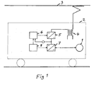
- Fig 1 illustrates schematically the arrangement and control of an electric synchronous machine 1 in a track-bound vehicle 2, such as a rail vehicle, for generating a traction force on this vehicle.
- the method according to the present invention is well suited for providing such an electric machine with a resolver in a state able to deliver information about the instantaneous position of a rotor of this machine with respect to a stator thereof.
- the vehicle is in this case configured to move along an AC-supply line 3, which accordingly acts as an AC source and which may for example carry a one-phase alternating voltage of 15 kV and 16 2/3 Hz (Sweden) and 25 kV and 50 Hz (Denmark).
- the invention is not restricted to such an AC source, but the vehicle may have any other conceivable corresponding source, such as a diesel motor.
- the vehicle has a transformer 4 for transforming the voltage from the supply line 3 to a suitable level.
- the secondary winding of the transformer is connected to a converter 5 making it possible to obtaining a control of the power flow between the supply line and the vehicle.
- This converter is controlled by a first control unit 6 for generating a direct voltage of for example 1.5 - 3 kV fed to a further converter 7 controlled through a second control unit 8 for generating a train of pulses according to a Pulse Width Modulation pattern for delivering a three-phase alternating voltage connected to the stator winding (not shown) of the electric machine 1 for driving the vehicle.
- control unit 8 It is important for the control unit 8 to know the instantaneous position of the rotor of the electric machine 1 with respect to the stator thereof, in fact the position of the rotor poles with respect to the stator winding, for applying a determined torque to the rotor with a minimum of electric power consumed, and this may be obtained by a said resolver associated with the electric machine 1.
- Fig 2 shows schematically in an axial end view some of the main parts of an electric machine to which a method according to the present invention is applicable.
- the invention is not restricted to any power levels of such machines, but these are normally designed to consume/deliver powers of some kV - several MW.
- This track-bound vehicle electric machine has a stator 9 with a stator body 10 with a stator winding 11 wound therearound and configured to electrically create a plurality of stator poles, in this case 4, disposed around the inner periphery of the stator body.
- the electric machine further comprises a rotor 12, which as the stator body is preferably made of a high number of thin steel laminates pressed together for keeping eddy current losses in these bodies at low levels.
- the rotor body 13 is rotatably disposed within the stator and has a plurality of permanent magnets 14 buried therein.
- the rotor body 13 is rigidly connected with respect to rotation to a rotor shaft 15, which is connected to the wheel axle of the vehicle 2, possibly through a gear box.
- the permanent magnets are arranged according to a "large V” and a “small V” per pole so as to form two north poles 16, 17 and two south poles 18, 19.
- a "large V” and a "small V” per pole so as to form two north poles 16, 17 and two south poles 18, 19.
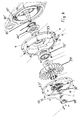
- Fig 3 illustrates more in detail a possible actual construction of such an electric machine by an exploded view of the nondrive end, i.e. the end opposite to said gear box, of a forced ventilated or water cooled such electric machine.
- a method according to an embodiment of the present invention for providing this electric machine 2 with a resolver in a state able to deliver information about the instantaneous position of a rotor of this machine with respect to a stator of the machine will now be described while simultaneously also making reference to Figs 4-7 .
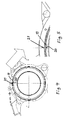
- the method comprises a step of fixing the stator winding 11 in a predetermined position with respect to the stator body 10, and this is obtained by aligning a predetermined point 20, as a starting point, of the stator winding with respect to a marking 21, such as optical or physical, on the stator body 10 (see Fig 4 and Fig 5 ) when fixing the winding with respect to the stator body.
- the marked stator wound shall in this embodiment line up to the vertical centre line of the stator body with an accuracy of +/- 5 mm for a radius of the stator body of 250 mm, although a lower accuracy, such as ⁇ 10 mm will also do.
- a shaft 15 onto which the rotor 12 is fixed by shrinkage is received in a ball bearing 23 surrounded by an inner bearing lid 24 and an outer bearing lid 25.
- the outer bearing lid 25 is connected to the inner bearing lid 24 by bolts 26 also fixing the bearing lids to an end shield 27 fixed to a stator body 10.
- a resolver stator 28 is through bolts 29 fixed in a predetermined position with respect to the machine stator by being fixed to the outer bearing lid.
- the bolts 29 of the resolver stator and corresponding holes in said bearing lid 25 are so arranged that the resolver stator may only be fixed to the bearing lid 25 in a determined position with respect thereto.
- the end of the rotor shaft 15 is provided with a blind hole 31 into which a pin 32 is inserted, and this pin enters into engagement with a corresponding slot formed in a resolver rotor 30 when mounting the resolver rotor 30 to the rotor shaft and by that fixing the resolver rotor in a only one possible predetermined position with respect to the machine rotor 12.
- the rotor shaft may instead be provided with a female member to be engaged with a male member in the resolver rotor.
- the machine rotor is made to rotate by controlling the converter 7 connected thereto and electric parameters influenced by this rotation are measured.
- the electric machine is mounted in a track-bound vehicle this means that the vehicle is started from a rest position.
- the relative position of the resolver rotor and the resolver stator is calculated as a measure of the relative position of the machine rotor and the machine stator by making the machine rotor rotate with a number of revolutions above a threshold value corresponding to such a high voltage applied across the stator winding that the actual torque applied by the stator winding on the rotor may be determined.
- the converter may then be controlled to deliver a zero torque to the rotor through the stator winding and the relative position of the resolver rotor and the resolver stator may be calculated under this zero torque condition.
- the software may by this connect each relative position of the resolver rotor and the resolver stator to a determined relative position of the machine rotor and the machine stator.
- Fig 8 is a view corresponding to Fig 3 indicating that a method according to the present invention may just as well be carried out for a self-ventilated electric machine, and parts corresponding to parts of the machine shown in Fig 3 have been provided with the same reference numerals added with an asterix. It is shown how this machine has also a fan casing 33, in which an impeller 34 secured to the rotor shaft 15' is received. The end shield 27' is here secured to the fan casing 33, which in its turn is secured to the stator body 10'.
Landscapes
- Engineering & Computer Science (AREA)
- Power Engineering (AREA)
- Life Sciences & Earth Sciences (AREA)
- Sustainable Development (AREA)
- Sustainable Energy (AREA)
- Transportation (AREA)
- Mechanical Engineering (AREA)
- Manufacturing & Machinery (AREA)
- Microelectronics & Electronic Packaging (AREA)
Abstract
Description
- The present invention relates to a method for providing an electric synchronous machine with a resolver in a state able to deliver information about the instantaneous position of a rotor of said machine with respect to a stator of the machine to be used for controlling exchange of electric power between a winding of said stator and an AC source or receiver.
- The synchronous machine may for instance be a reluctance machine or a permanent magnet machine, and a machine of the latter type will hereinafter mainly be discussed for illustrating the invention but not in any way restrict the invention thereto.
- Although an electric machine of this type may operate as motor and/or generator this disclosure will focus mainly on the operation thereof as a motor.
- In a permanent magnet machine the rotor has a plurality of permanent magnets, which may be buried in the rotor body or arranged on the circumferential surface thereof. By using a plurality of permanent magnets to produce the magnetic flux of the rotor a motor having lower rotor losses compared to an induction motor and thus higher efficiency will be achieved. It can also be built with a higher pole number, compared to an induction motor, without sacrificing performance, so that it can have a higher torque capability, features making such an electric machine particularly interesting as a track-bound vehicle electric machine for which a high torque capability with respect to a determined size of the motor is an important feature. This is also the reason why this particular application of such a machine will hereinafter be described without the purpose to restrict the invention thereto, but the invention is just as well applicable to machines used for instance within the industry, especially heavy such machines and/or machines operating at a high power, such as above 10 kW.
- The reason for providing such a machine with a resolver is that it is for the efficiency of such a machine essential to with a high accuracy know the instantaneous position of the machine rotor with respect to the machine stator. Would the exchange of electric power between the stator winding and said AC source or receiver be controlled with even a minor incorrect assumption of said position this would result in substantial losses of electric power. A resolver has a resolver stator to be fixed with respect to the stator of the electric machine and a resolver rotor to be fixed with respect to the rotor of the machine. The resolver stator is normally built up of a magnetic flux carrying structure, and the resolver rotor may have a winding or not. There are different known ways to provide such an electric machine with a resolver in said state able to deliver information about the instantaneous position of the machine rotor with respect to the machine stator. These methods are rather complicated and do in some cases require a software adapted for each individual electric machine. The provision of the machine with a resolver in such a state may take place when the electric machine is mounted for the first use thereof, such as in connection with mounting the machine into a track-bound vehicle. However, the method may also be carried out when any part of the resolver or the entire resolver is replaced and a new resolver is mounted to the electric machine or other types of maintenance is carried out on the electric machine which may influence the state of such a resolver.
- The object of the present invention is to provide a method of the type defined in the introduction being improved in at least some aspect with respect to such methods already known.
- This object is according to the invention obtained by providing such a method, which comprises the following steps:
- a) fixing said stator winding in a predetermined position with respect to said machine stator,
- b) fixing a resolver stator in a predetermined position with respect to said machine stator,
- c) fixing a resolver rotor in a predetermined position with respect to said machine rotor,
- d) making the machine rotor rotate and measuring electric parameters influenced by this rotation, and
- e) calculating, by use of software, the relative position of the resolver rotor and the resolver stator as a measure of the relative position of the machine rotor and the machine stator, so that the instantaneous relative position of the machine rotor with respect to the machine stator after that is known by knowledge of the relative position of the resolver rotor with respect to the resolver stator for use when controlling said exchange of electric power,
- By fixing the stator winding, the resolver stator and the resolver rotor in these predetermined positions it may in a simple way be ensured that a certain relative position of the resolver stator and the resolver rotor predicts a relative position of the machine rotor and the machine stator within such a narrow interval that it will be possible to with a high accuracy determine this relative position as a measure of the relative position of the machine rotor and the machine stator by making the machine rotor rotate and measuring electric parameters influenced by this rotation. This may easily be obtained by the use of software.
- According to an embodiment of the invention step a) comprises aligning of a predetermined point, such as a starting point, of said stator winding with respect to a marking, such as optical or physical, on a stator body when fixing said winding with respect to the stator body. The stator winding may for instance be shrunk in place on a stator body, and it is then easy to ensure that a particular point of the stator winding is brought into alignment with a marking on the stator body, so that the position of the stator winding in the stator body is well known.
- According to another embodiment of the invention step b) comprises aligning of the resolver stator with respect to the machine stator, such as by introduction of male members in female members, such as bolts in holes, when fixing the resolver stator with respect to the machine stator. This results in a possibility to with a high accuracy arrange the resolver stator in a certain relative position with respect to said stator winding.
- According to another embodiment of the invention the resolver stator is aligned with respect to said machine stator by fixing the resolver stator by means allowing such fixing in only one possible position, which ensures achievement of a minimum of deviation of the position of the resolver stator from an optimum position thereof with respect to the machine stator winding.
- According to another embodiment of the invention the method comprises a step of fixing a stator body of said machine stator in a predetermined position to a framework, such as a stator house, and in step b) the resolver stator is secured to said framework in a predetermined position and by that in a predetermined position with respect to the machine stator. Accordingly, the fixing of the resolver stator with respect to the machine stator may be just as well obtained by fixing the resolver stator to another body, such as a framework, to which or with respect to which the machine stator is fixed.
- According to another embodiment of the invention step c) comprises fixing of the resolver rotor in a predetermined position to a shaft of the machine rotor. The rotor shaft is mostly comparatively well accessible, so that this is mostly an advantageous way to fix the resolver rotor with respect to the machine rotor.
- According to another embodiment of the invention the resolver rotor is in step c) brought into only one possible position for fixing it with respect to the machine rotor when carrying out this fixing, and the step c) may then also comprise bringing engagement means of the resolver rotor into engagement with engagement means of said rotor shaft when fixing the resolver rotor to this shaft.
- According to another embodiment of the invention steps a) - c) are carried out with an accuracy with respect to obtaining said predetermined positions resulting in a maximum possible deviation of the machine rotor position in which the resolver rotor and the resolver stator is in a predetermined relationship from the machine rotor position in which the machine rotor and the machine stator is in the same predetermined relationship below a predetermined value, in which this predetermined value is a mechanical angle of 360°/2(number of poles of the rotor). By applying such an accuracy when carrying out the steps a) - c) it is ensured that it is known which resolver pole is in a position adjacent to a machine rotor pole.
- According to another embodiment of the invention the method is carried out on an electric machine having 8 poles on the rotor and 4 poles on the resolver rotor, and the step a) - c) are carried out so that said predetermined value of maximum deviation is below 22.5°, preferably below 10°. The deviation of the electricial angle has theoretically to be below 90° for enabling a calibration of the resolver. That would mean a maximum deviation of the mechanical angle in this case of 90/4 = 22.5°. However, parameters of the machine and possibly also other parameters, such as for a machine used in a railway vehicle the torque needed to move the vehicle, may make it preferred to restrict the maximum deviation of the electrical angle to be 40° which in this embodiment means a corresponding maximum deviation of the mechanical angle of 10°.
- According to another embodiment of the invention step d) is carried out by controlling a converter connected to an electric power source to deliver an alternating voltage to said stator winding by Pulse Width Modulation for rotating the machine rotor.
- According to another embodiment of the invention said converter is in step e) controlled to make the machine rotor rotate with a number of revolutions above a threshold value corresponding to such a high voltage applied across the stator winding that the actual torque applied by the stator winding on the rotor may be determined, and the converter is then controlled to deliver zero torque to the rotor through the stator winding and the relative position of the resolver rotor and the resolver stator is in step e) determined under this zero torque condition. It will by this be known in which relative position the machine rotor and the machine stator are for a certain relative position of the resolver rotor and the resolver stator.
- According to another embodiment of the invention the method is carried out on a track-bound vehicle electric machine, which constitutes a particularly advantageous application of the present invention.
- According to another embodiment of the invention the method is carried out upon an electric machine mounted in a track-bound vehicle, and step d) is carried out by driving the vehicle from a rest position. The resolver may by this be brought into a state in which it is able to reliably deliver information about the instantaneous position of the machine rotor with respect to the machine stator for use for controlling said exchange of electric power before any currents are generated which may be harmful to the electric machine or equipment associated therewith.
- According to another embodiment of the invention the method is carried out on an electric machine with a rotor having a plurality of permanent magnets, which is one preferred application of the present invention.
- According to another embodiment of the invention the method is carried out on an electric machine designed to be connected to a said AC source delivering an alternating voltage to said stator winding of 500 V - 5 kV or 1.5 - 3.5 kV.
- Further advantages as well as advantageous features of the invention will appear from the following description of embodiments of the invention.
- With reference to the appended drawings, below follows a specific description of embodiments of the invention cited as examples.
- In the drawings:
- Fig 1
- is a very schematic view illustrating how a track-bound vehicle electric machine of the type to which the method according to the present invention may be directed may be connected and controlled in such a vehicle,
- Fig 2
- is a very schematic side elevation view illustrating the stator and the rotor of an electric machine of the type to which a method according to the present invention may be applied,
- Fig 3
- is an exploded view illustrating how a method according to an embodiment of the present invention
- Fig 4 and 5
- may be carried out on a force ventilated or water cooled electric permanent magnet machine, are very schematic views illustrating how the machine stator winding is aligned with a stator house,
- Fig 6 and 7
- are simplified views used to illustrate the fixing of the resolver rotor in a predetermined position with respect to the machine rotor for the machine shown in
Fig 3 , and - Fig 8
- is a view corresponding to
Fig 3 illustrating a method according to another embodiment of the invention carried out on a self-ventilated electric machine. -
Fig 1 illustrates schematically the arrangement and control of an electricsynchronous machine 1 in a track-boundvehicle 2, such as a rail vehicle, for generating a traction force on this vehicle. The method according to the present invention is well suited for providing such an electric machine with a resolver in a state able to deliver information about the instantaneous position of a rotor of this machine with respect to a stator thereof. It is shown how the vehicle is in this case configured to move along an AC-supply line 3, which accordingly acts as an AC source and which may for example carry a one-phase alternating voltage of 15 kV and 16 2/3 Hz (Sweden) and 25 kV and 50 Hz (Denmark). However, the invention is not restricted to such an AC source, but the vehicle may have any other conceivable corresponding source, such as a diesel motor. - The vehicle has a transformer 4 for transforming the voltage from the
supply line 3 to a suitable level. The secondary winding of the transformer is connected to aconverter 5 making it possible to obtaining a control of the power flow between the supply line and the vehicle. This converter is controlled by a first control unit 6 for generating a direct voltage of for example 1.5 - 3 kV fed to afurther converter 7 controlled through asecond control unit 8 for generating a train of pulses according to a Pulse Width Modulation pattern for delivering a three-phase alternating voltage connected to the stator winding (not shown) of theelectric machine 1 for driving the vehicle. It is important for thecontrol unit 8 to know the instantaneous position of the rotor of theelectric machine 1 with respect to the stator thereof, in fact the position of the rotor poles with respect to the stator winding, for applying a determined torque to the rotor with a minimum of electric power consumed, and this may be obtained by a said resolver associated with theelectric machine 1. -
Fig 2 shows schematically in an axial end view some of the main parts of an electric machine to which a method according to the present invention is applicable. The invention is not restricted to any power levels of such machines, but these are normally designed to consume/deliver powers of some kV - several MW. This track-bound vehicle electric machine has astator 9 with astator body 10 with a stator winding 11 wound therearound and configured to electrically create a plurality of stator poles, in this case 4, disposed around the inner periphery of the stator body. - The electric machine further comprises a
rotor 12, which as the stator body is preferably made of a high number of thin steel laminates pressed together for keeping eddy current losses in these bodies at low levels. Therotor body 13 is rotatably disposed within the stator and has a plurality ofpermanent magnets 14 buried therein. Therotor body 13 is rigidly connected with respect to rotation to arotor shaft 15, which is connected to the wheel axle of thevehicle 2, possibly through a gear box. - The permanent magnets are arranged according to a "large V" and a "small V" per pole so as to form two
north poles south poles converter 7 it is vital to continuously know the relative position of these rotor poles with respect to the stator poles. -
Fig 3 illustrates more in detail a possible actual construction of such an electric machine by an exploded view of the nondrive end, i.e. the end opposite to said gear box, of a forced ventilated or water cooled such electric machine. A method according to an embodiment of the present invention for providing thiselectric machine 2 with a resolver in a state able to deliver information about the instantaneous position of a rotor of this machine with respect to a stator of the machine will now be described while simultaneously also making reference toFigs 4-7 . The method comprises a step of fixing the stator winding 11 in a predetermined position with respect to thestator body 10, and this is obtained by aligning apredetermined point 20, as a starting point, of the stator winding with respect to a marking 21, such as optical or physical, on the stator body 10 (seeFig 4 and Fig 5 ) when fixing the winding with respect to the stator body. The marked stator wound shall in this embodiment line up to the vertical centre line of the stator body with an accuracy of +/- 5 mm for a radius of the stator body of 250 mm, although a lower accuracy, such as ±10 mm will also do. - A
shaft 15 onto which therotor 12 is fixed by shrinkage is received in aball bearing 23 surrounded by aninner bearing lid 24 and anouter bearing lid 25. Theouter bearing lid 25 is connected to theinner bearing lid 24 bybolts 26 also fixing the bearing lids to anend shield 27 fixed to astator body 10. Aresolver stator 28 is throughbolts 29 fixed in a predetermined position with respect to the machine stator by being fixed to the outer bearing lid. Thebolts 29 of the resolver stator and corresponding holes in said bearinglid 25 are so arranged that the resolver stator may only be fixed to the bearinglid 25 in a determined position with respect thereto. - The end of the
rotor shaft 15 is provided with ablind hole 31 into which apin 32 is inserted, and this pin enters into engagement with a corresponding slot formed in aresolver rotor 30 when mounting theresolver rotor 30 to the rotor shaft and by that fixing the resolver rotor in a only one possible predetermined position with respect to themachine rotor 12. Alternatively, the rotor shaft may instead be provided with a female member to be engaged with a male member in the resolver rotor. - When all these mounting work has been done the machine rotor is made to rotate by controlling the
converter 7 connected thereto and electric parameters influenced by this rotation are measured. When the electric machine is mounted in a track-bound vehicle this means that the vehicle is started from a rest position. The relative position of the resolver rotor and the resolver stator is calculated as a measure of the relative position of the machine rotor and the machine stator by making the machine rotor rotate with a number of revolutions above a threshold value corresponding to such a high voltage applied across the stator winding that the actual torque applied by the stator winding on the rotor may be determined. The converter may then be controlled to deliver a zero torque to the rotor through the stator winding and the relative position of the resolver rotor and the resolver stator may be calculated under this zero torque condition. The software may by this connect each relative position of the resolver rotor and the resolver stator to a determined relative position of the machine rotor and the machine stator. -
Fig 8 is a view corresponding toFig 3 indicating that a method according to the present invention may just as well be carried out for a self-ventilated electric machine, and parts corresponding to parts of the machine shown inFig 3 have been provided with the same reference numerals added with an asterix. It is shown how this machine has also a fan casing 33, in which animpeller 34 secured to the rotor shaft 15' is received. The end shield 27' is here secured to the fan casing 33, which in its turn is secured to the stator body 10'. - The invention is of course not in any way restricted to the embodiments described above, but many possibilities to modifications thereof would be apparent to a person with ordinary skill in the art without departing from the scope of the invention as defined in the appended claims.
Claims (16)
- A method for providing an electric synchronous machine (2) with a resolver in a state able to deliver information about the instantaneous position of a rotor (12) of said machine with respect to a stator (9) of the machine to be used for controlling exchange of electric power between a winding (11) of said stator and an AC source or receiver (3) comprises the following steps:a) fixing said stator winding (9) in a predetermined position with respect to said machine stator (11),b) fixing a resolver stator (28) in a predetermined position with respect to said machine stator (11),c) fixing a resolver rotor (30) in a predetermined position with respect to said machine rotor (12),d) making the machine rotor rotate and measuring electric parameters influenced by this rotation, ande) calculating, by use of software, the relative position of the resolver rotor (30) and the resolver stator (28) as a measure of the relative position of the machine rotor (12) and the machine stator (9), so that the instantaneous relative position of the machine rotor with respect to the machine stator after that is known by knowledge of the relative position of the resolver rotor with respect to the resolver stator for use when controlling said exchange of electric power,in which the steps a), b) and c) may be carried out in an arbitrary order.
- A method according to claim 1, characterized in that step a) comprises aligning of a predetermined point, such as a starting point (20), of said stator winding (11) with respect to a marking (21), such as optical or physical, on a stator body (10) when fixing said winding with respect to this stator body.
- A method according to claim 1 or 2, characterized in that step b) comprises aligning of the resolver stator (28) with respect to the machine stator (9), such as by introduction of male members (29) in female members, such as bolts in holes, when fixing the resolver stator with respect to the machine stator.
- A method according to claim 3, characterized in that said resolver stator (28) is aligned with respect to said machine stator (9) by fixing the resolver stator by means allowing such fixing in only one possible position.
- A method according to any of the preceding claims, characterized in that it comprises the step of fixing a stator body (10) of said machine stator in a predetermined position to a framework, such as a stator house, and that in step b) the resolver stator (28) is secured to said framework in a predetermined position and by that in a predetermined position with respect to the machine stator (9).
- A method according to any of the preceding claims, characterized in that step c) comprises fixing of the resolver rotor (30) in a predetermined position to a shaft (15) of the machine rotor (12).
- A method according to any of the preceding claims, characterized in that in step c) said resolver rotor (30) is brought into only one possible position for fixing it with respect to the machine rotor (12) when carrying out this fixing.
- A method according to claims 6 and 7, characterized in that step c) comprises bringing engagement means of the resolver rotor (30) into engagement with engagement means (32) on said rotor shaft (15) when fixing the resolver rotor to this shaft.
- A method according to any of the preceding claims, characterized in that the steps a) - c) are carried out with an accuracy with respect to obtaining said predetermined positions resulting in a maximum possible deviation of the machine rotor position in which the resolver rotor (30) and the resolver stator (28) is in a predetermined relationship from the machine rotor position in which the machine rotor (12) and the machine stator (9) is in the same predetermined relationship below a predetermined value, in which this predetermined value is a mechanical angle of 360°/2(number of poles of the rotor).
- A method according to claim 9, characterized in that it is carried out on an electric machine having 8 poles on the rotor and 4 poles on the resolver rotor, and that the step a) - c) are carried out so that said predetermined value of maximum deviation is below 22.5°, preferably below 10°.
- A method according to any of the preceding claims, characterized in that step d) is carried out by controlling a converter (7) connected to an electric power source to deliver an alternating voltage to said stator winding (11) by Pulse Width Modulation for rotating the machine rotor (12).
- A method according to claim 11, characterized in that said converter is in step d) controlled to make the machine rotor (12) rotate with a number of revolutions above a threshold value corresponding to such a high voltage applied across the stator winding (11) that the actual torque applied by the stator winding on the rotor may be determined, and that the converter (7) is then controlled to deliver a zero torque to the rotor (12) through the stator winding (11) and the relative position of the resolver rotor (30) and the resolver stator (28) is in step e) determined under this zero torque condition.
- A method according to any of the preceding claims, characterized in that it is carried out on a track-bound vehicle electric machine (1).
- A method according to claim 13, characterized in that it is carried out upon an electric machine (1) mounted in a track-bound vehicle (2), and that step d) is carried out by driving the vehicle from a rest position.
- A method according to any of the preceding claims, characterized in that it is carried out on an electric machine (1) with a rotor (12) having a plurality of permanent magnets (14).
- A method according to any of the preceding claims, characterized in that it is carried out on an electric machine (1) designed to be connected to a said AC source (3) delivering an alternating voltage to said stator winding of 500 V - 5 kV or 1.5 - 3.5 kV.
Priority Applications (3)
| Application Number | Priority Date | Filing Date | Title |
|---|---|---|---|
| PL11159834T PL2503676T3 (en) | 2011-03-25 | 2011-03-25 | A method for mounting a resolver |
| EP11159834.8A EP2503676B1 (en) | 2011-03-25 | 2011-03-25 | A method for mounting a resolver |
| CN201210239261.XA CN102761301B (en) | 2011-03-25 | 2012-03-26 | For the method installing solver |
Applications Claiming Priority (1)
| Application Number | Priority Date | Filing Date | Title |
|---|---|---|---|
| EP11159834.8A EP2503676B1 (en) | 2011-03-25 | 2011-03-25 | A method for mounting a resolver |
Publications (2)
| Publication Number | Publication Date |
|---|---|
| EP2503676A1 true EP2503676A1 (en) | 2012-09-26 |
| EP2503676B1 EP2503676B1 (en) | 2018-10-17 |
Family
ID=44802585
Family Applications (1)
| Application Number | Title | Priority Date | Filing Date |
|---|---|---|---|
| EP11159834.8A Active EP2503676B1 (en) | 2011-03-25 | 2011-03-25 | A method for mounting a resolver |
Country Status (3)
| Country | Link |
|---|---|
| EP (1) | EP2503676B1 (en) |
| CN (1) | CN102761301B (en) |
| PL (1) | PL2503676T3 (en) |
Families Citing this family (1)
| Publication number | Priority date | Publication date | Assignee | Title |
|---|---|---|---|---|
| PL237542B1 (en) * | 2019-10-11 | 2021-04-19 | Siec Badawcza Lukasiewicz Instytut Napedow I Masz Elektrycznych Komel | Method for accurate alignment of the resolver on the shaft of an electric machine |
Citations (2)
| Publication number | Priority date | Publication date | Assignee | Title |
|---|---|---|---|---|
| US20090167121A1 (en) * | 2007-12-27 | 2009-07-02 | Showa Corporation | Positioning mechanism of resolver and electrically -driven power steering apparatus |
| US20110066327A1 (en) * | 2009-09-17 | 2011-03-17 | Hitachi Automotive Systems, Ltd. | Power steering apparatus |
Family Cites Families (4)
| Publication number | Priority date | Publication date | Assignee | Title |
|---|---|---|---|---|
| US6756757B2 (en) * | 2002-05-21 | 2004-06-29 | Emerson Electric Company | Control system and method for a rotating electromagnetic machine |
| EP2151918A1 (en) * | 2008-08-07 | 2010-02-10 | Bombardier Transportation GmbH | Operating a synchronous motor having a permanent magnet rotor |
| FR2935564A1 (en) * | 2008-09-03 | 2010-03-05 | Michelin Soc Tech | DEVICE FOR MOUNTING A RESOLVER IN AN ELECTRIC MACHINE |
| US8054084B2 (en) * | 2009-05-19 | 2011-11-08 | GM Global Technology Operations LLC | Methods and systems for diagnosing stator windings in an electric motor |
-
2011
- 2011-03-25 EP EP11159834.8A patent/EP2503676B1/en active Active
- 2011-03-25 PL PL11159834T patent/PL2503676T3/en unknown
-
2012
- 2012-03-26 CN CN201210239261.XA patent/CN102761301B/en not_active Expired - Fee Related
Patent Citations (2)
| Publication number | Priority date | Publication date | Assignee | Title |
|---|---|---|---|---|
| US20090167121A1 (en) * | 2007-12-27 | 2009-07-02 | Showa Corporation | Positioning mechanism of resolver and electrically -driven power steering apparatus |
| US20110066327A1 (en) * | 2009-09-17 | 2011-03-17 | Hitachi Automotive Systems, Ltd. | Power steering apparatus |
Also Published As
| Publication number | Publication date |
|---|---|
| EP2503676B1 (en) | 2018-10-17 |
| CN102761301A (en) | 2012-10-31 |
| CN102761301B (en) | 2016-11-02 |
| PL2503676T3 (en) | 2019-02-28 |
Similar Documents
| Publication | Publication Date | Title |
|---|---|---|
| EP1870987B1 (en) | Method and apparatus for monitoring rotary machines | |
| EP2161821B1 (en) | Magnetically geared generator | |
| JP5363913B2 (en) | Rotating electric machine drive system | |
| US20130207498A1 (en) | Synchronous motor | |
| US20250141280A1 (en) | Radial flux electrical machines | |
| US20100001533A1 (en) | Alternator | |
| EP3309945A1 (en) | Rotary electric machine and non-contact power generator | |
| WO2008111776A3 (en) | Electric motor | |
| EP2592728B1 (en) | Electromagnetic device | |
| CN113258726B (en) | Motor with inductive position sensor assembly and method of assembling and aligning the same | |
| RU2395714C1 (en) | Electric generator stator | |
| AU2010330123A1 (en) | Electric machine | |
| CN114977662A (en) | Rotor for an electrical machine and electrical machine having a rotor | |
| CN202395540U (en) | High-quality three-phase AC permanent magnetic servo synchronous motor | |
| EP2503676B1 (en) | A method for mounting a resolver | |
| US20250357834A1 (en) | Rotor for an electric machine, electric machine, motor vehicle and method for determining a rotor position of a rotor | |
| Kallaste et al. | Analysis of the eccentricity in a low-speed slotless permanent-magnet wind generator | |
| JP2010166787A (en) | Rotating electrical machine | |
| CN213279305U (en) | Novel anti-string permanent magnet generator | |
| US11296635B2 (en) | Control system for motor | |
| US20200328664A1 (en) | Generator device of electrical energy with permanent magnets, particularly for the supply of electrical loads and/or batteries of vehicles | |
| US20160329788A1 (en) | Shaftless generator | |
| JP3175706U (en) | Coreless generator and micro hydro power generation system using the same | |
| CN103731000A (en) | Reversing direct-current motor with magnetic poles formed by combined permanent magnets | |
| Haller et al. | Investigation of a 2 v 1.1 kw mosfet commutated dc motor |
Legal Events
| Date | Code | Title | Description |
|---|---|---|---|
| PUAI | Public reference made under article 153(3) epc to a published international application that has entered the european phase |
Free format text: ORIGINAL CODE: 0009012 |
|
| AK | Designated contracting states |
Kind code of ref document: A1 Designated state(s): AL AT BE BG CH CY CZ DE DK EE ES FI FR GB GR HR HU IE IS IT LI LT LU LV MC MK MT NL NO PL PT RO RS SE SI SK SM TR |
|
| AX | Request for extension of the european patent |
Extension state: BA ME |
|
| 17P | Request for examination filed |
Effective date: 20130326 |
|
| REG | Reference to a national code |
Ref country code: DE Ref legal event code: R079 Ref document number: 602011052907 Country of ref document: DE Free format text: PREVIOUS MAIN CLASS: H02K0011000000 Ipc: B60L0009280000 |
|
| GRAP | Despatch of communication of intention to grant a patent |
Free format text: ORIGINAL CODE: EPIDOSNIGR1 |
|
| STAA | Information on the status of an ep patent application or granted ep patent |
Free format text: STATUS: GRANT OF PATENT IS INTENDED |
|
| RIC1 | Information provided on ipc code assigned before grant |
Ipc: H02K 15/00 20060101ALI20180423BHEP Ipc: H02K 11/225 20160101ALI20180423BHEP Ipc: B60L 9/28 20060101AFI20180423BHEP |
|
| INTG | Intention to grant announced |
Effective date: 20180511 |
|
| GRAS | Grant fee paid |
Free format text: ORIGINAL CODE: EPIDOSNIGR3 |
|
| GRAA | (expected) grant |
Free format text: ORIGINAL CODE: 0009210 |
|
| STAA | Information on the status of an ep patent application or granted ep patent |
Free format text: STATUS: THE PATENT HAS BEEN GRANTED |
|
| AK | Designated contracting states |
Kind code of ref document: B1 Designated state(s): AL AT BE BG CH CY CZ DE DK EE ES FI FR GB GR HR HU IE IS IT LI LT LU LV MC MK MT NL NO PL PT RO RS SE SI SK SM TR |
|
| REG | Reference to a national code |
Ref country code: GB Ref legal event code: FG4D |
|
| REG | Reference to a national code |
Ref country code: CH Ref legal event code: EP Ref country code: CH Ref legal event code: NV Representative=s name: P&TS SA, CH |
|
| RAP2 | Party data changed (patent owner data changed or rights of a patent transferred) |
Owner name: BOMBARDIER TRANSPORTATION GMBH |
|
| REG | Reference to a national code |
Ref country code: IE Ref legal event code: FG4D |
|
| REG | Reference to a national code |
Ref country code: DE Ref legal event code: R096 Ref document number: 602011052907 Country of ref document: DE Ref country code: AT Ref legal event code: REF Ref document number: 1053582 Country of ref document: AT Kind code of ref document: T Effective date: 20181115 |
|
| REG | Reference to a national code |
Ref country code: SE Ref legal event code: TRGR |
|
| REG | Reference to a national code |
Ref country code: NL Ref legal event code: MP Effective date: 20181017 |
|
| REG | Reference to a national code |
Ref country code: LT Ref legal event code: MG4D |
|
| PG25 | Lapsed in a contracting state [announced via postgrant information from national office to epo] |
Ref country code: NL Free format text: LAPSE BECAUSE OF FAILURE TO SUBMIT A TRANSLATION OF THE DESCRIPTION OR TO PAY THE FEE WITHIN THE PRESCRIBED TIME-LIMIT Effective date: 20181017 |
|
| PG25 | Lapsed in a contracting state [announced via postgrant information from national office to epo] |
Ref country code: ES Free format text: LAPSE BECAUSE OF FAILURE TO SUBMIT A TRANSLATION OF THE DESCRIPTION OR TO PAY THE FEE WITHIN THE PRESCRIBED TIME-LIMIT Effective date: 20181017 Ref country code: LV Free format text: LAPSE BECAUSE OF FAILURE TO SUBMIT A TRANSLATION OF THE DESCRIPTION OR TO PAY THE FEE WITHIN THE PRESCRIBED TIME-LIMIT Effective date: 20181017 Ref country code: FI Free format text: LAPSE BECAUSE OF FAILURE TO SUBMIT A TRANSLATION OF THE DESCRIPTION OR TO PAY THE FEE WITHIN THE PRESCRIBED TIME-LIMIT Effective date: 20181017 Ref country code: NO Free format text: LAPSE BECAUSE OF FAILURE TO SUBMIT A TRANSLATION OF THE DESCRIPTION OR TO PAY THE FEE WITHIN THE PRESCRIBED TIME-LIMIT Effective date: 20190117 Ref country code: IS Free format text: LAPSE BECAUSE OF FAILURE TO SUBMIT A TRANSLATION OF THE DESCRIPTION OR TO PAY THE FEE WITHIN THE PRESCRIBED TIME-LIMIT Effective date: 20190217 Ref country code: LT Free format text: LAPSE BECAUSE OF FAILURE TO SUBMIT A TRANSLATION OF THE DESCRIPTION OR TO PAY THE FEE WITHIN THE PRESCRIBED TIME-LIMIT Effective date: 20181017 Ref country code: HR Free format text: LAPSE BECAUSE OF FAILURE TO SUBMIT A TRANSLATION OF THE DESCRIPTION OR TO PAY THE FEE WITHIN THE PRESCRIBED TIME-LIMIT Effective date: 20181017 Ref country code: BG Free format text: LAPSE BECAUSE OF FAILURE TO SUBMIT A TRANSLATION OF THE DESCRIPTION OR TO PAY THE FEE WITHIN THE PRESCRIBED TIME-LIMIT Effective date: 20190117 |
|
| PG25 | Lapsed in a contracting state [announced via postgrant information from national office to epo] |
Ref country code: GR Free format text: LAPSE BECAUSE OF FAILURE TO SUBMIT A TRANSLATION OF THE DESCRIPTION OR TO PAY THE FEE WITHIN THE PRESCRIBED TIME-LIMIT Effective date: 20190118 Ref country code: PT Free format text: LAPSE BECAUSE OF FAILURE TO SUBMIT A TRANSLATION OF THE DESCRIPTION OR TO PAY THE FEE WITHIN THE PRESCRIBED TIME-LIMIT Effective date: 20190217 Ref country code: AL Free format text: LAPSE BECAUSE OF FAILURE TO SUBMIT A TRANSLATION OF THE DESCRIPTION OR TO PAY THE FEE WITHIN THE PRESCRIBED TIME-LIMIT Effective date: 20181017 Ref country code: RS Free format text: LAPSE BECAUSE OF FAILURE TO SUBMIT A TRANSLATION OF THE DESCRIPTION OR TO PAY THE FEE WITHIN THE PRESCRIBED TIME-LIMIT Effective date: 20181017 |
|
| REG | Reference to a national code |
Ref country code: DE Ref legal event code: R097 Ref document number: 602011052907 Country of ref document: DE |
|
| PG25 | Lapsed in a contracting state [announced via postgrant information from national office to epo] |
Ref country code: CZ Free format text: LAPSE BECAUSE OF FAILURE TO SUBMIT A TRANSLATION OF THE DESCRIPTION OR TO PAY THE FEE WITHIN THE PRESCRIBED TIME-LIMIT Effective date: 20181017 Ref country code: DK Free format text: LAPSE BECAUSE OF FAILURE TO SUBMIT A TRANSLATION OF THE DESCRIPTION OR TO PAY THE FEE WITHIN THE PRESCRIBED TIME-LIMIT Effective date: 20181017 Ref country code: IT Free format text: LAPSE BECAUSE OF FAILURE TO SUBMIT A TRANSLATION OF THE DESCRIPTION OR TO PAY THE FEE WITHIN THE PRESCRIBED TIME-LIMIT Effective date: 20181017 |
|
| PLBE | No opposition filed within time limit |
Free format text: ORIGINAL CODE: 0009261 |
|
| STAA | Information on the status of an ep patent application or granted ep patent |
Free format text: STATUS: NO OPPOSITION FILED WITHIN TIME LIMIT |
|
| PG25 | Lapsed in a contracting state [announced via postgrant information from national office to epo] |
Ref country code: SK Free format text: LAPSE BECAUSE OF FAILURE TO SUBMIT A TRANSLATION OF THE DESCRIPTION OR TO PAY THE FEE WITHIN THE PRESCRIBED TIME-LIMIT Effective date: 20181017 Ref country code: RO Free format text: LAPSE BECAUSE OF FAILURE TO SUBMIT A TRANSLATION OF THE DESCRIPTION OR TO PAY THE FEE WITHIN THE PRESCRIBED TIME-LIMIT Effective date: 20181017 Ref country code: EE Free format text: LAPSE BECAUSE OF FAILURE TO SUBMIT A TRANSLATION OF THE DESCRIPTION OR TO PAY THE FEE WITHIN THE PRESCRIBED TIME-LIMIT Effective date: 20181017 Ref country code: SM Free format text: LAPSE BECAUSE OF FAILURE TO SUBMIT A TRANSLATION OF THE DESCRIPTION OR TO PAY THE FEE WITHIN THE PRESCRIBED TIME-LIMIT Effective date: 20181017 |
|
| 26N | No opposition filed |
Effective date: 20190718 |
|
| PG25 | Lapsed in a contracting state [announced via postgrant information from national office to epo] |
Ref country code: SI Free format text: LAPSE BECAUSE OF FAILURE TO SUBMIT A TRANSLATION OF THE DESCRIPTION OR TO PAY THE FEE WITHIN THE PRESCRIBED TIME-LIMIT Effective date: 20181017 Ref country code: MC Free format text: LAPSE BECAUSE OF FAILURE TO SUBMIT A TRANSLATION OF THE DESCRIPTION OR TO PAY THE FEE WITHIN THE PRESCRIBED TIME-LIMIT Effective date: 20181017 |
|
| PG25 | Lapsed in a contracting state [announced via postgrant information from national office to epo] |
Ref country code: LU Free format text: LAPSE BECAUSE OF NON-PAYMENT OF DUE FEES Effective date: 20190325 |
|
| REG | Reference to a national code |
Ref country code: BE Ref legal event code: MM Effective date: 20190331 |
|
| PG25 | Lapsed in a contracting state [announced via postgrant information from national office to epo] |
Ref country code: IE Free format text: LAPSE BECAUSE OF NON-PAYMENT OF DUE FEES Effective date: 20190325 |
|
| PG25 | Lapsed in a contracting state [announced via postgrant information from national office to epo] |
Ref country code: BE Free format text: LAPSE BECAUSE OF NON-PAYMENT OF DUE FEES Effective date: 20190331 |
|
| PG25 | Lapsed in a contracting state [announced via postgrant information from national office to epo] |
Ref country code: TR Free format text: LAPSE BECAUSE OF FAILURE TO SUBMIT A TRANSLATION OF THE DESCRIPTION OR TO PAY THE FEE WITHIN THE PRESCRIBED TIME-LIMIT Effective date: 20181017 |
|
| PG25 | Lapsed in a contracting state [announced via postgrant information from national office to epo] |
Ref country code: MT Free format text: LAPSE BECAUSE OF NON-PAYMENT OF DUE FEES Effective date: 20190325 |
|
| PG25 | Lapsed in a contracting state [announced via postgrant information from national office to epo] |
Ref country code: CY Free format text: LAPSE BECAUSE OF FAILURE TO SUBMIT A TRANSLATION OF THE DESCRIPTION OR TO PAY THE FEE WITHIN THE PRESCRIBED TIME-LIMIT Effective date: 20181017 |
|
| PG25 | Lapsed in a contracting state [announced via postgrant information from national office to epo] |
Ref country code: HU Free format text: LAPSE BECAUSE OF FAILURE TO SUBMIT A TRANSLATION OF THE DESCRIPTION OR TO PAY THE FEE WITHIN THE PRESCRIBED TIME-LIMIT; INVALID AB INITIO Effective date: 20110325 |
|
| PG25 | Lapsed in a contracting state [announced via postgrant information from national office to epo] |
Ref country code: MK Free format text: LAPSE BECAUSE OF FAILURE TO SUBMIT A TRANSLATION OF THE DESCRIPTION OR TO PAY THE FEE WITHIN THE PRESCRIBED TIME-LIMIT Effective date: 20181017 |
|
| REG | Reference to a national code |
Ref country code: AT Ref legal event code: UEP Ref document number: 1053582 Country of ref document: AT Kind code of ref document: T Effective date: 20181017 |
|
| P01 | Opt-out of the competence of the unified patent court (upc) registered |
Effective date: 20230822 |
|
| PGFP | Annual fee paid to national office [announced via postgrant information from national office to epo] |
Ref country code: AT Payment date: 20240321 Year of fee payment: 14 |
|
| PGFP | Annual fee paid to national office [announced via postgrant information from national office to epo] |
Ref country code: DE Payment date: 20240320 Year of fee payment: 14 Ref country code: GB Payment date: 20240320 Year of fee payment: 14 |
|
| PGFP | Annual fee paid to national office [announced via postgrant information from national office to epo] |
Ref country code: SE Payment date: 20240320 Year of fee payment: 14 |
|
| PGFP | Annual fee paid to national office [announced via postgrant information from national office to epo] |
Ref country code: CH Payment date: 20240401 Year of fee payment: 14 |
|
| PGFP | Annual fee paid to national office [announced via postgrant information from national office to epo] |
Ref country code: PL Payment date: 20240314 Year of fee payment: 14 |
|
| REG | Reference to a national code |
Ref country code: DE Ref legal event code: R119 Ref document number: 602011052907 Country of ref document: DE |
|
| REG | Reference to a national code |
Ref country code: CH Ref legal event code: H13 Free format text: ST27 STATUS EVENT CODE: U-0-0-H10-H13 (AS PROVIDED BY THE NATIONAL OFFICE) Effective date: 20251023 |
|
| REG | Reference to a national code |
Ref country code: SE Ref legal event code: EUG |
|
| REG | Reference to a national code |
Ref country code: AT Ref legal event code: MM01 Ref document number: 1053582 Country of ref document: AT Kind code of ref document: T Effective date: 20250325 |
|
| GBPC | Gb: european patent ceased through non-payment of renewal fee |
Effective date: 20250325 |
|
| PG25 | Lapsed in a contracting state [announced via postgrant information from national office to epo] |
Ref country code: DE Free format text: LAPSE BECAUSE OF NON-PAYMENT OF DUE FEES Effective date: 20251001 |
|
| PG25 | Lapsed in a contracting state [announced via postgrant information from national office to epo] |
Ref country code: GB Free format text: LAPSE BECAUSE OF NON-PAYMENT OF DUE FEES Effective date: 20250325 |
|
| PG25 | Lapsed in a contracting state [announced via postgrant information from national office to epo] |
Ref country code: AT Free format text: LAPSE BECAUSE OF NON-PAYMENT OF DUE FEES Effective date: 20250325 |
|
| PG25 | Lapsed in a contracting state [announced via postgrant information from national office to epo] |
Ref country code: CH Free format text: LAPSE BECAUSE OF NON-PAYMENT OF DUE FEES Effective date: 20250331 |
|
| PG25 | Lapsed in a contracting state [announced via postgrant information from national office to epo] |
Ref country code: SE Free format text: LAPSE BECAUSE OF NON-PAYMENT OF DUE FEES Effective date: 20250326 |
|
| PGFP | Annual fee paid to national office [announced via postgrant information from national office to epo] |
Ref country code: FR Payment date: 20260320 Year of fee payment: 16 |