EP2503641A1 - Actuating system for antenna reflector with deformable reflecting surface - Google Patents
Actuating system for antenna reflector with deformable reflecting surface Download PDFInfo
- Publication number
- EP2503641A1 EP2503641A1 EP12159584A EP12159584A EP2503641A1 EP 2503641 A1 EP2503641 A1 EP 2503641A1 EP 12159584 A EP12159584 A EP 12159584A EP 12159584 A EP12159584 A EP 12159584A EP 2503641 A1 EP2503641 A1 EP 2503641A1
- Authority
- EP
- European Patent Office
- Prior art keywords
- axis
- along
- deformation
- flexible membrane
- actuating
- Prior art date
- Legal status (The legal status is an assumption and is not a legal conclusion. Google has not performed a legal analysis and makes no representation as to the accuracy of the status listed.)
- Granted
Links
- 239000012528 membrane Substances 0.000 claims abstract description 44
- 238000006073 displacement reaction Methods 0.000 description 4
- 230000005540 biological transmission Effects 0.000 description 2
- 239000000463 material Substances 0.000 description 2
- 239000003638 chemical reducing agent Substances 0.000 description 1
- 230000000694 effects Effects 0.000 description 1
- 239000002923 metal particle Substances 0.000 description 1
- 238000000034 method Methods 0.000 description 1
- 230000003287 optical effect Effects 0.000 description 1
- 229920001296 polysiloxane Polymers 0.000 description 1
Images

Classifications
-
- H—ELECTRICITY
- H01—ELECTRIC ELEMENTS
- H01Q—ANTENNAS, i.e. RADIO AERIALS
- H01Q15/00—Devices for reflection, refraction, diffraction or polarisation of waves radiated from an antenna, e.g. quasi-optical devices
- H01Q15/14—Reflecting surfaces; Equivalent structures
- H01Q15/148—Reflecting surfaces; Equivalent structures with means for varying the reflecting properties
-
- H—ELECTRICITY
- H01—ELECTRIC ELEMENTS
- H01Q—ANTENNAS, i.e. RADIO AERIALS
- H01Q3/00—Arrangements for changing or varying the orientation or the shape of the directional pattern of the waves radiated from an antenna or antenna system
- H01Q3/01—Arrangements for changing or varying the orientation or the shape of the directional pattern of the waves radiated from an antenna or antenna system varying the shape of the antenna or antenna system
-
- H—ELECTRICITY
- H01—ELECTRIC ELEMENTS
- H01Q—ANTENNAS, i.e. RADIO AERIALS
- H01Q15/00—Devices for reflection, refraction, diffraction or polarisation of waves radiated from an antenna, e.g. quasi-optical devices
- H01Q15/14—Reflecting surfaces; Equivalent structures
-
- H—ELECTRICITY
- H01—ELECTRIC ELEMENTS
- H01Q—ANTENNAS, i.e. RADIO AERIALS
- H01Q15/00—Devices for reflection, refraction, diffraction or polarisation of waves radiated from an antenna, e.g. quasi-optical devices
- H01Q15/14—Reflecting surfaces; Equivalent structures
- H01Q15/147—Reflecting surfaces; Equivalent structures provided with means for controlling or monitoring the shape of the reflecting surface
-
- G—PHYSICS
- G02—OPTICS
- G02B—OPTICAL ELEMENTS, SYSTEMS OR APPARATUS
- G02B26/00—Optical devices or arrangements for the control of light using movable or deformable optical elements
- G02B26/08—Optical devices or arrangements for the control of light using movable or deformable optical elements for controlling the direction of light
- G02B26/0816—Optical devices or arrangements for the control of light using movable or deformable optical elements for controlling the direction of light by means of one or more reflecting elements
- G02B26/0825—Optical devices or arrangements for the control of light using movable or deformable optical elements for controlling the direction of light by means of one or more reflecting elements the reflecting element being a flexible sheet or membrane, e.g. for varying the focus
Definitions
- the invention lies in the field of antenna reflectors with a deformable reflective surface. It relates to an actuating system that can equip such a reflector.
- a telecommunications satellite has at least one antenna for transmitting and receiving electromagnetic signals.
- Each antenna has a reflector whose shape and orientation determine the terrestrial area covered by the antenna.
- a satellite may comprise several antennas, each antenna covering a specific terrestrial area.
- the number of antennas that can equip a satellite is limited by the space available under the launcher cover of the satellite.
- One solution to this double problem is to design an antenna reflector whose reflective surface is deformable.
- Antenna reflectors with a deformable reflecting surface having a flexible membrane and an actuating system comprising a plurality of push elements are known.
- the flexible membrane may be treated to form a reflective surface.
- Each pusher element comprises a rod and an actuator of the stepper motor or piezoelectric motor type.
- Each rod comes into contact with a point of the flexible membrane and can be driven in translation by the actuator so as to locally deform the flexible membrane.
- the set of push elements generally allows to give a particular shape to the flexible membrane. The deformation of the flexible membrane being made in a discrete manner, it is desirable to multiply the push elements to allow forming a smoothest and most regular reflective surface possible.
- each actuator must be energized electric and individually controlled. This results in a complex electrical interface to implement. In the case where the actuators are piezoelectric motors, they must be powered continuously, even when they must not actuate the rod.
- the actuating device is able to generate a rotational movement relative to the support along the axis, said rotational movement transmitting a translational movement to the pusher element by means of a screw system. /nut.
- Each first rotatable member may include a first pulley and each second rotatable member may include a second pulley.
- Each deformation device then comprises, in addition, a belt connecting the first pulley to the second pulley. This pulley / belt system makes it possible to arrange the deformation devices relatively far from each other.
- the first rotary elements are distributed over the perimeter of a circle
- the selection device comprising a support arm that can be rotated along a third axis passing through the center of the circle and orthogonal to the plane of the circle.
- the actuating device being fixed on the support arm so as to be able to rotate the first rotary members of the deformation devices.
- the actuating device comprises for example a motor adapted to rotate each first rotary element along its second axis.
- the actuation system further comprises, for at least one deformation device, an elastic element whose one of its ends is linked in translation along the first axis with the part of the pusher element. adapted to come into contact with the flexible membrane and another of its ends is linked in translation along the first axis with the flexible membrane, the elastic element being elastically deformable along the first axis.
- the actuating system may comprise, for each deformation device comprising an elastic element, a second elastic element whose one end is linked in translation along the first axis with the support. and of which another of its ends is linked in translation along the first axis with the flexible membrane, the second elastic element being elastically deformable along the first axis, the stiffness of the first elastic element along the first axis being smaller than the stiffness of the second element elastic according to the first axis.
- the invention also relates to a reflector comprising a frame, a flexible membrane fixed to the frame so as to be deformed, and an actuating system as described above.
- the invention has the particular advantage that it allows the actuating system to have only one actuator for all points of deformation of the flexible membrane.
- the figure 1 represents, in a sectional view, an example of a parabolic antenna reflector with a deformable reflective surface according to the state of the art.
- the antenna reflector 10 comprises a fixed frame 11, a flexible membrane 12 and an actuating system 13 for deforming the flexible membrane 12 at different points, called deformation points 121.
- the flexible membrane 12 is fixed at its periphery to the chassis 11. It comprises a reflective surface 122 of substantially parabolic shape able to reflect electromagnetic waves in a predetermined frequency band, chosen according to the intended application.
- the reflecting surface 122 is for example formed by metal particles deposited on the surface of the flexible membrane 12.
- the flexibility of the membrane 12 can be obtained by joints or by an elastically deformable material.
- the material of the flexible membrane 12 comprises, for example, silicone.
- the actuating system 13 comprises a support 131 fixed to the frame 11 under the flexible membrane 12, that is to say on the opposite side to the reflecting surface 122, and a set of pushing elements 132.
- the actuating system 13 may comprise about one hundred pushing elements 132 distributed under the flexible membrane 12.
- Each pusher element 132 comprises a rod 1321 and an actuator 1322 for driving the rod 1321 in translation.
- a free end of each rod 1321 comes into contact with a deformation point 121 of the flexible membrane 12.
- a ball joint can be provided between the free ends of the rods 1321 and the deformation points 121.
- the actuators 1322 are fixed to the support 131. They can be fixed to the support 131 via ball joints.
- the pushing elements 132 are represented on the figure 1 in the form of cylinders, in which case each rod 1321 may correspond to the rod of the associated cylinder.
- the push members 132 may be electric cylinders, stepper motors or piezoelectric motors.
- the actuators 1322 can be controlled to deform the flexible membrane 12 at the deformation points 121.
- the figure 2 represents, in a sectional view, an example of reflector with deformable reflective surface comprising an actuating system according to the invention.
- the reflector may have a parabolic shape or any other form adapted to a specific use.
- the reflector can equip an antenna of a telecommunications satellite. It can also be used in an optical system as a mirror.
- the reflector 20 differs essentially from the reflector 10 described with reference to the figure 1 by its actuation system.
- the reflector 20 comprises a fixed frame, not shown, a flexible membrane 12 and an actuating system 23 for deforming the flexible membrane 12 at different deformation points 121.
- the actuating system 23 comprises a fixed structure 231 forming a support, a selection device 232, an actuating device 233 and a set of deformation 234.
- On the figure 2 only one deformation device 234 is shown for readability reasons. The invention is nevertheless of particular interest when the actuation system comprises several deformation devices, which may for example be up to several hundred.
- Each deformation device 234 comprises, for example, a first pulley 2341, a second pulley 2342, a belt 2343 connecting the pulleys 2341 and 2342, a nut 2344 and a threaded rod 2345 cooperating with the nut 2344.
- the first pulley 2341 is in contact with each other.
- the pivot connection is for example made by means of a bearing 2346.
- the second pulley 2342 is pivotally connected relative to the fixed structure 231 along a second axis X 2 , substantially parallel to the first axis X 1 .
- the second pulley 2342 is connected in rotation with the nut 2344, which is pivotally connected along the axis X 2 relative to the fixed structure 231.
- the nut 2344 forms for example a bearing for the second pulley 2342.
- One end of the threaded rod 2345 is fixed at a point of deformation 121 of the flexible membrane 12 so as to be translationally and rotationally connected along the axis X 2 with the flexible membrane 12.
- the second pulley 2342 is connected in rotation with the threaded rod 2345.
- the nut 2344 is rotatably connected along the axis X 2 with the fixed structure 231.
- the end of the threaded rod 2345 is fixed at the point deformation 121 so as to be linked in translation and free in rotation along the axis X 2 with respect to the flexible membrane 12.
- the end of the threaded rod 2345 is for example connected to the point of deformation 121 by a pivot connection according to the X axis 2 .
- a rotation of the second pulley 2342 along the axis X 2 causes a translation of the threaded rod 2345 along this axis in one direction or the other, according to the direction of rotation of the second pulley 2342.
- the flexible membrane 12 is thus deformed locally.
- the actuating device 233 rotates the first pulley 2341 of each deformation device 234 and, by means of the belts 2343, the second pulleys 2342. It comprises an actuator 2331, such as a step motor. a piezoelectric motor, and a driving part 2332 which can be driven in rotation by the actuator 2331 along an axis substantially parallel to the axis X 1 .
- the drive part 2332 is configured to be able to couple with each first pulley 2341.
- the drive part 2332 comprises a tip of the flat screwdriver type, and the first pulleys 2341 each comprise a suitable footprint. to receive this tip.
- This type of tip allows engagement and disengagement between the driving part 2332 and the impression of the first pulley 2341 during the rotational displacement of the actuating device 233 by the selection device 232, without requiring any movement of the translation along the axis X 1 .
- the training part 2332 must then perform a whole number of half-turns.
- the selection device 232 makes it possible to move the actuating device 233 towards each of the deformation devices 234, so that the actuating device 233 can rotate the first pulley 2341 of the selected deformation device 234.
- the selection device 232 comprises an electric motor 2321 and a support arm 2322.
- the electric motor 2321 is adapted to rotate the support arm 2322 along a third axis X 3 , substantially parallel to the axes X 1 and X 2 .
- the actuating device 233 is fixed on the support arm 2322.
- the first pulleys 2341 of each deformation device 234 are mounted on the fixed structure 231 in a circular distribution.
- the actuating device 233 can thus come opposite each pulley 2341 by a rotation of the support arm 2322 along the axis X 3 , and the deformation devices 234 can be actuated successively.
- the location of the pulleys 2341 is constrained by the circular displacement of the actuating device 233, the second pulleys 2342 can be freely distributed on the fixed structure 231 thanks to the belts 2343.
- the actuating system 23 has been described with reference to the figure 2 considering transmissions of rotary movements between the actuating device 233 and the various threaded rods 2345 by means of a pulleys and belts. Nevertheless, the transmissions can also be made by chains or by gears.
- the mechanical connections between the ends of the threaded rods 2345 and the flexible membrane 12 may be, as in the exemplary embodiments shown in FIGS. Figures 1 and 2 , links eliminating the degree of freedom in translation along the axis X 2 between the threaded rods 2345 and the membrane 12. It is for example flush connections or ball joints.
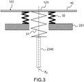
- the figure 3 represents, in a cross-sectional view, an example of a mechanical connection that can be made between the end of a rod 2345 and the flexible membrane 12.
- the link 30 comprises a first elastic element 31 fixed at one of its ends to the end of the threaded rod 2345 and at its other end to the point of deformation 121 of the flexible membrane 12.
- the link 30 may also comprise a second elastic element 32 fixed at one of its ends to the fixed structure 231 of the flexible system. actuation 23 and at its other end to the flexible membrane 12, in the vicinity of the point of deformation 121.
- the elastic elements 31 and 32 may be elastically deformed along the axis X 2 .
- the elastic elements 31 and 32 are two coaxial helical springs.
- the inner diameter of the second coil spring 32 is greater than the outer diameter of the first coil spring 31 so as to allow its free passage.
- Each elastic element may comprise one or more springs, in series or in parallel.
- the stiffness k 1 of the first elastic element 31 is substantially smaller than the stiffness k 2 of the second elastic element 32.
- connection 30 thus forms a system with a differential stiffness having the effect of limiting the deformation of the flexible membrane 12. More precisely for a displacement of a given length of the threaded rod 2345 along the axis X 2 , the deformation point 121 moves along this axis by a shorter length. It is thus possible to deform the flexible membrane 12 with greater precision.
- Other solutions may be envisaged to reduce the displacement of the threaded rods 2345. By way of example, it is possible to add, between a second pulley 2342 and a deformation point 121, a gear reducer or a micrometer screw. also called Prony differential screw.
Abstract
Description
L'invention se situe dans le domaine des réflecteurs d'antenne à surface réfléchissante déformable. Elle concerne un système d'actionnement pouvant équiper un tel réflecteur.The invention lies in the field of antenna reflectors with a deformable reflective surface. It relates to an actuating system that can equip such a reflector.
Un satellite de télécommunications comporte au moins une antenne permettant l'émission et la réception de signaux électromagnétiques. Chaque antenne comporte un réflecteur dont la forme et l'orientation déterminent la zone terrestre couverte par l'antenne. Dans le but de couvrir plusieurs zones terrestres distinctes ou une zone terrestre plus étendue que celle pouvant être couverte par une seule antenne, un satellite peut comporter plusieurs antennes, chaque antenne couvrant une zone terrestre spécifique. Cependant, le nombre d'antennes pouvant équiper un satellite est limité par l'espace disponible sous la coiffe du lanceur du satellite. Par ailleurs, il peut être souhaitable de pouvoir modifier la zone terrestre couverte par une antenne. Une solution pour répondre à ce double problème est de concevoir un réflecteur d'antenne dont la surface réfléchissante est déformable.A telecommunications satellite has at least one antenna for transmitting and receiving electromagnetic signals. Each antenna has a reflector whose shape and orientation determine the terrestrial area covered by the antenna. In order to cover several distinct terrestrial areas or a larger terrestrial area than can be covered by a single antenna, a satellite may comprise several antennas, each antenna covering a specific terrestrial area. However, the number of antennas that can equip a satellite is limited by the space available under the launcher cover of the satellite. In addition, it may be desirable to be able to modify the terrestrial area covered by an antenna. One solution to this double problem is to design an antenna reflector whose reflective surface is deformable.
On connaît des réflecteurs d'antenne à surface réfléchissante déformable comportant une membrane flexible et un système d'actionnement comprenant une pluralité d'éléments poussoirs. La membrane flexible peut être traitée afin de former une surface réfléchissante. Chaque élément poussoir comprend une tige et un actionneur du type moteur pas à pas ou moteur piézoélectrique. Chaque tige vient au contact d'un point de la membrane flexible et peut être entraînée en translation par l'actionneur de manière à déformer localement la membrane flexible. L'ensemble des éléments poussoirs permet globalement de donner une forme particulière à la membrane flexible. La déformation de la membrane flexible étant réalisée de manière discrète, il est souhaitable de multiplier les éléments poussoirs pour permettre de former une surface réfléchissante la plus lisse et la plus régulière possible. Cependant, la multiplication des éléments poussoirs implique une masse, un encombrement et un coût élevés pour le système d'actionnement. De plus, chaque actionneur doit être alimenté en énergie électrique et commandé individuellement. Il en résulte une interface électrique complexe à mettre en oeuvre. Dans le cas où les actionneurs sont des moteurs piézoélectriques, ils doivent être alimentés en permanence, même lorsqu'ils ne doivent pas actionner la tige.Antenna reflectors with a deformable reflecting surface having a flexible membrane and an actuating system comprising a plurality of push elements are known. The flexible membrane may be treated to form a reflective surface. Each pusher element comprises a rod and an actuator of the stepper motor or piezoelectric motor type. Each rod comes into contact with a point of the flexible membrane and can be driven in translation by the actuator so as to locally deform the flexible membrane. The set of push elements generally allows to give a particular shape to the flexible membrane. The deformation of the flexible membrane being made in a discrete manner, it is desirable to multiply the push elements to allow forming a smoothest and most regular reflective surface possible. However, the multiplication of the push elements implies a mass, a bulk and a high cost for the actuating system. In addition, each actuator must be energized electric and individually controlled. This results in a complex electrical interface to implement. In the case where the actuators are piezoelectric motors, they must be powered continuously, even when they must not actuate the rod.
Un but de l'invention est notamment de pallier tout ou partie des inconvénients précités en proposant un système d'actionnement pour un réflecteur d'antenne à surface réfléchissante déformable qui soit simple, économique, léger, et qui permette une déformation de la surface réfléchissante en de nombreux points. A cet effet, l'invention a pour objet un système d'actionnement pouvant équiper un réflecteur comportant un châssis et une membrane flexible fixée au châssis de manière à pouvoir être déformée. Selon l'invention, le système d'actionnement comporte :
- ■ un support apte à être fixé au châssis du réflecteur,
- ■ un ensemble de dispositifs de déformation, chaque dispositif de déformation comportant un élément poussoir apte à être entraîné en translation par rapport au support selon un axe, l'élément poussoir comportant une partie apte à venir au contact de la membrane flexible en un point pour la déformer,
- ■ un dispositif d'actionnement apte à entraîner en translation l'élément poussoir de l'un des dispositifs de déformation à la fois selon son axe, et
- ■ un dispositif de sélection apte à déplacer le dispositif d'actionnement vers chacun des dispositifs de déformation de manière à ce que le dispositif d'actionnement puisse entraîner en translation l'élément poussoir du dispositif de déformation sélectionné.
- A support adapted to be fixed to the reflector frame,
- A set of deformation devices, each deformation device comprising a pusher element adapted to be driven in translation relative to the support along an axis, the pusher element comprising a portion adapted to come into contact with the flexible membrane at a point to deform,
- An actuating device capable of translational driving the pusher element of one of the deformation devices at a time along its axis, and
- A selection device adapted to move the actuating device to each of the deformation devices so that the actuating device can translate the pusher element of the selected deformation device.
Selon une forme particulière de réalisation, le dispositif d'actionnement est apte à générer un mouvement de rotation par rapport au support selon l'axe, ledit mouvement de rotation transmettant un mouvement de translation à l'élément poussoir au moyen d'un système vis/écrou.According to a particular embodiment, the actuating device is able to generate a rotational movement relative to the support along the axis, said rotational movement transmitting a translational movement to the pusher element by means of a screw system. /nut.
Chaque dispositif de déformation peut alors comporter, en outre :
- ■ un premier élément rotatif apte à être entraîné en rotation par rapport au support selon un deuxième axe, sensiblement parallèle au premier axe, par le dispositif d'actionnement, et
- ■ un deuxième élément rotatif lié en rotation selon le premier axe avec l'un des éléments du système vis/écrou et pouvant être entraîné en rotation selon le premier axe par le premier élément rotatif.
- A first rotary element adapted to be rotated relative to the support along a second axis, substantially parallel to the first axis, by the actuating device, and
- A second rotary element rotatably connected along the first axis with one of the elements of the screw / nut system and capable of being rotated along the first axis by the first rotary element.
Chaque premier élément rotatif peut comporter une première poulie et chaque deuxième élément rotatif peut comporter une deuxième poulie. Chaque dispositif de déformation comporte alors, en outre, une courroie reliant la première poulie à la deuxième poulie. Ce système poulies /courroie permet de disposer les dispositifs de déformation relativement loin les uns des autres.Each first rotatable member may include a first pulley and each second rotatable member may include a second pulley. Each deformation device then comprises, in addition, a belt connecting the first pulley to the second pulley. This pulley / belt system makes it possible to arrange the deformation devices relatively far from each other.
Toujours selon une forme particulière de réalisation, les premiers éléments rotatifs sont répartis sur le périmètre d'un cercle, le dispositif de sélection comportant un bras support pouvant être entraîné en rotation selon un troisième axe passant par le centre du cercle et orthogonal au plan du cercle, le dispositif d'actionnement étant fixé sur le bras support de manière à pouvoir entraîner en rotation les premiers éléments rotatifs des dispositifs de déformation.Still according to a particular embodiment, the first rotary elements are distributed over the perimeter of a circle, the selection device comprising a support arm that can be rotated along a third axis passing through the center of the circle and orthogonal to the plane of the circle. circle, the actuating device being fixed on the support arm so as to be able to rotate the first rotary members of the deformation devices.
Le dispositif d'actionnement comporte par exemple un moteur apte à entraîner en rotation chaque premier élément rotatif selon son deuxième axe.The actuating device comprises for example a motor adapted to rotate each first rotary element along its second axis.
Selon une forme particulière de réalisation, le système d'actionnement comporte de plus, pour au moins un dispositif de déformation, un élément élastique dont l'une de ses extrémités est liée en translation selon le premier axe avec la partie de l'élément poussoir apte à venir au contact de la membrane flexible et dont une autre de ses extrémités est liée en translation selon le premier axe avec la membrane flexible, l'élément élastique étant déformable élastiquement selon le premier axe.According to a particular embodiment, the actuation system further comprises, for at least one deformation device, an elastic element whose one of its ends is linked in translation along the first axis with the part of the pusher element. adapted to come into contact with the flexible membrane and another of its ends is linked in translation along the first axis with the flexible membrane, the elastic element being elastically deformable along the first axis.
Selon cette forme particulière de réalisation, le système d'actionnement peut comporter, pour chaque dispositif de déformation comportant un élément élastique, un deuxième élément élastique dont l'une de ses extrémités est liée en translation selon le premier axe avec le support et dont une autre de ses extrémités est liée en translation selon le premier axe avec la membrane flexible, le deuxième élément élastique étant déformable élastiquement selon le premier axe, la raideur du premier élément élastique selon le premier axe étant inférieure à la raideur du deuxième élément élastique selon le premier axe.According to this particular embodiment, the actuating system may comprise, for each deformation device comprising an elastic element, a second elastic element whose one end is linked in translation along the first axis with the support. and of which another of its ends is linked in translation along the first axis with the flexible membrane, the second elastic element being elastically deformable along the first axis, the stiffness of the first elastic element along the first axis being smaller than the stiffness of the second element elastic according to the first axis.
L'invention a également pour objet un réflecteur comportant un châssis, une membrane flexible fixée au châssis de manière à pouvoir être déformée, et un système d'actionnement tel que décrit ci-dessus.The invention also relates to a reflector comprising a frame, a flexible membrane fixed to the frame so as to be deformed, and an actuating system as described above.
L'invention a notamment pour avantage qu'elle permet au système d'actionnement de ne comporter qu'un seul actionneur pour l'ensemble des points de déformation de la membrane flexible.The invention has the particular advantage that it allows the actuating system to have only one actuator for all points of deformation of the flexible membrane.
L'invention sera mieux comprise et d'autres avantages apparaîtront à la lecture de la description qui va suivre, faite en regard de dessins annexés sur lesquels :
- la
figure 1 , dans une vue en coupe, un exemple de réflecteur d'antenne parabolique à surface réfléchissante déformable selon l'état de la technique ; - la
figure 2 , dans une vue en coupe, un exemple de réflecteur à surface réfléchissante déformable selon l'invention ; - la
figure 3 , dans une vue en coupe, un exemple de liaison mécanique entre un dispositif de déformation et la surface réfléchissante.
- the
figure 1 , in a cross-sectional view, an example of a parabolic antenna reflector with a deformable reflective surface according to the state of the art; - the
figure 2 , in a sectional view, an example of reflector with deformable reflective surface according to the invention; - the
figure 3 , in a sectional view, an example of mechanical connection between a deformation device and the reflecting surface.
La
La
Le dispositif d'actionnement 233 permet d'entraîner en rotation la première poulie 2341 de chaque dispositif de déformation 234 et, par l'intermédiaire des courroies 2343, les deuxièmes poulies 2342. Il comporte un actionneur 2331, tel qu'un moteur pas à pas ou un moteur piézoélectrique, et une pièce d'entraînement 2332 pouvant être entraînée en rotation par l'actionneur 2331 selon un axe sensiblement parallèle à l'axe X1. La pièce d'entraînement 2332 est configurée pour pouvoir venir s'accoupler avec chaque première poulie 2341. A titre d'exemple, la pièce d'entraînement 2332 comporte un embout de type tournevis plat, et les premières poulies 2341 comportent chacune une empreinte apte à recevoir cet embout. Ce type d'embout permet un engagement et un désengagement entre la pièce d'entraînement 2332 et l'empreinte de la première poulie 2341 lors du déplacement en rotation du dispositif d'actionnement 233 par le dispositif de sélection 232, sans nécessiter de mouvement de translation selon l'axe X1. La pièce d'entrainement 2332 doit alors effectuer un nombre entier de demi-tours.The
Le dispositif de sélection 232 permet de déplacer le dispositif d'actionnement 233 vers chacun des dispositifs de déformation 234, de manière à ce que le dispositif d'actionnement 233 puisse entraîner en rotation la première poulie 2341 du dispositif de déformation 234 sélectionné. Selon une forme particulière de réalisation, le dispositif de sélection 232 comporte un moteur électrique 2321 et un bras support 2322. Le moteur électrique 2321 est apte à entraîner en rotation le bras support 2322 selon un troisième axe X3, sensiblement parallèle aux axes X1 et X2. Le dispositif d'actionnement 233 est fixé sur le bras support 2322. Dans cette forme particulière de réalisation, les premières poulies 2341 de chaque dispositif de déformation 234 sont montées sur la structure fixe 231 selon une répartition circulaire. Le dispositif d'actionnement 233 peut ainsi venir en vis-à-vis de chaque poulie 2341 par une rotation du bras support 2322 selon l'axe X3, et les dispositifs de déformation 234 peuvent être actionnés successivement. Bien que l'emplacement des poulies 2341 soit contraint par le déplacement circulaire du dispositif d'actionnement 233, les deuxièmes poulies 2342 peuvent être réparties librement sur la structure fixe 231 grâce aux courroies 2343.The
Le système d'actionnement 23 a été décrit en référence à la
Les liaisons mécaniques entre les extrémités des tiges filetées 2345 et la membrane flexible 12 peuvent être, comme dans les exemples de réalisation représentés sur les
Claims (9)
Applications Claiming Priority (1)
| Application Number | Priority Date | Filing Date | Title |
|---|---|---|---|
| FR1100887A FR2973168B1 (en) | 2011-03-24 | 2011-03-24 | ACTUATING SYSTEM FOR ANTENNA REFLECTOR WITH DEFORMABLE REFLECTIVE SURFACE |
Publications (2)
| Publication Number | Publication Date |
|---|---|
| EP2503641A1 true EP2503641A1 (en) | 2012-09-26 |
| EP2503641B1 EP2503641B1 (en) | 2013-08-28 |
Family
ID=45808359
Family Applications (1)
| Application Number | Title | Priority Date | Filing Date |
|---|---|---|---|
| EP12159584.7A Active EP2503641B1 (en) | 2011-03-24 | 2012-03-15 | Actuating system for antenna reflector with deformable reflecting surface |
Country Status (6)
| Country | Link |
|---|---|
| US (1) | US8803761B2 (en) |
| EP (1) | EP2503641B1 (en) |
| JP (1) | JP5998410B2 (en) |
| CN (1) | CN102694273B (en) |
| ES (1) | ES2433007T3 (en) |
| FR (1) | FR2973168B1 (en) |
Cited By (1)
| Publication number | Priority date | Publication date | Assignee | Title |
|---|---|---|---|---|
| EP2808943A1 (en) * | 2013-05-31 | 2014-12-03 | Thales | Method for producing an antenna reflector with formed surface, reflector with formed surface obtained by said method and antenna comprising such a reflector |
Families Citing this family (11)
| Publication number | Priority date | Publication date | Assignee | Title |
|---|---|---|---|---|
| FR2989229B1 (en) * | 2012-04-06 | 2015-03-06 | Thales Sa | RECONFIGURABLE ANTENNA REFLECTOR IN SERVICE |
| US9337544B2 (en) * | 2013-01-07 | 2016-05-10 | Lockheed Martin Corporation | Configurable backing structure for a reflector antenna and corrective synthesis for mechanical adjustment thereof |
| JP2014160211A (en) * | 2013-02-20 | 2014-09-04 | Canon Inc | Mirror unit and image acquisition device |
| US9577344B2 (en) * | 2013-11-27 | 2017-02-21 | The United States of Americ as represented by the Secretary of the Air Force | Actuated pin antenna reflector |
| JP6501793B2 (en) * | 2014-04-04 | 2019-04-17 | カール・ツァイス・エスエムティー・ゲーエムベーハー | Optical module with deforming device and method for deforming an optical element |
| RU2576493C2 (en) * | 2014-06-17 | 2016-03-10 | Государственное казенное образовательное учреждение высшего профессионального образования Академия Федеральной службы охраны Российской Федерации (Академия ФСО России) | Method for synthesis of shape of reflecting surface of mirror-type antenna system |
| CN107210536B (en) * | 2014-12-05 | 2021-07-30 | Nsl通讯有限公司 | Remotely tunable antenna assemblies and sub-reflectors therefor and related methods |
| US9774093B2 (en) * | 2015-03-20 | 2017-09-26 | The Boeing Company | Automated reflector tuning systems and methdos |
| JP6559737B2 (en) * | 2017-06-21 | 2019-08-14 | ソフトバンク株式会社 | Non-feed relay device and wireless relay system |
| EP3745182A1 (en) * | 2019-05-28 | 2020-12-02 | Nederlandse Organisatie voor toegepast- natuurwetenschappelijk Onderzoek TNO | Controllably deformable mirror device |
| KR102238357B1 (en) * | 2019-12-05 | 2021-04-08 | 에스케이텔레콤 주식회사 | Changeable Passive Relay, Controlling Server, and Operating Method thereof |
Citations (2)
| Publication number | Priority date | Publication date | Assignee | Title |
|---|---|---|---|---|
| FR2678111A1 (en) * | 1991-06-19 | 1992-12-24 | Aerospatiale | RECONFIGURABLE ANTENNA REFLECTOR IN SERVICE. |
| WO2009092901A1 (en) * | 2007-11-02 | 2009-07-30 | Ujf-Filiale | Deformable mirror with distributed stiffness, tool and method for producing such a mirror |
Family Cites Families (13)
| Publication number | Priority date | Publication date | Assignee | Title |
|---|---|---|---|---|
| JPS6032411A (en) * | 1983-08-03 | 1985-02-19 | Nippon Telegr & Teleph Corp <Ntt> | Mirror surface control antenna reflection mirror |
| FR2646023B1 (en) * | 1989-04-18 | 1991-06-14 | Europ Agence Spatiale | ANTENNA POINTING DEVICE, SATELLITE PROVIDED WITH SUCH A DEVICE AND ANTENNA POINTING METHOD USING SUCH A DEVICE |
| EP0648324B1 (en) * | 1992-06-23 | 1998-11-11 | Commonwealth Scientific And Industrial Research Organisation | Method and apparatus of stud array upstand setting |
| JP3311028B2 (en) * | 1992-07-14 | 2002-08-05 | 株式会社東芝 | Surface shape adjustment system |
| US5831780A (en) * | 1996-01-31 | 1998-11-03 | Raytheon Company | Continually supported thin mirror with force-type actuators |
| JPH10135729A (en) * | 1996-10-24 | 1998-05-22 | Nippon Telegr & Teleph Corp <Ntt> | Cable film surface support method and device |
| US6104358A (en) * | 1998-05-12 | 2000-08-15 | Trw Inc. | Low cost deployable reflector |
| WO2002061488A1 (en) * | 2001-01-30 | 2002-08-08 | Matsushita Electric Industrial Co., Ltd. | Variable mirror and information apparatus comprising variable mirror |
| JP2003302568A (en) * | 2002-04-11 | 2003-10-24 | Mitsubishi Electric Corp | Reflection surface adjuster |
| US6989922B2 (en) * | 2002-06-21 | 2006-01-24 | Nikon Corporation | Deformable mirror actuation system |
| US7113322B2 (en) * | 2004-06-23 | 2006-09-26 | Reflectivity, Inc | Micromirror having offset addressing electrode |
| FR2903387B1 (en) * | 2006-07-05 | 2008-08-29 | Alcatel Sa | ACTUATOR FOR SYSTEMS FOR GUIDING SPACE EQUIPMENTS WITH VARIABLE ROTATION RATIOS |
| CN101179157B (en) * | 2007-11-14 | 2011-01-26 | 清华大学 | Large-scale radio telescope active reflecting plane common drive parallel mechanism array |
-
2011
- 2011-03-24 FR FR1100887A patent/FR2973168B1/en not_active Expired - Fee Related
-
2012
- 2012-03-15 ES ES12159584T patent/ES2433007T3/en active Active
- 2012-03-15 EP EP12159584.7A patent/EP2503641B1/en active Active
- 2012-03-21 JP JP2012063992A patent/JP5998410B2/en active Active
- 2012-03-21 CN CN201210076477.9A patent/CN102694273B/en active Active
- 2012-03-23 US US13/429,159 patent/US8803761B2/en active Active
Patent Citations (2)
| Publication number | Priority date | Publication date | Assignee | Title |
|---|---|---|---|---|
| FR2678111A1 (en) * | 1991-06-19 | 1992-12-24 | Aerospatiale | RECONFIGURABLE ANTENNA REFLECTOR IN SERVICE. |
| WO2009092901A1 (en) * | 2007-11-02 | 2009-07-30 | Ujf-Filiale | Deformable mirror with distributed stiffness, tool and method for producing such a mirror |
Cited By (3)
| Publication number | Priority date | Publication date | Assignee | Title |
|---|---|---|---|---|
| EP2808943A1 (en) * | 2013-05-31 | 2014-12-03 | Thales | Method for producing an antenna reflector with formed surface, reflector with formed surface obtained by said method and antenna comprising such a reflector |
| FR3006504A1 (en) * | 2013-05-31 | 2014-12-05 | Thales Sa | METHOD FOR PRODUCING AN ANTENNA REFLECTOR WITH A FORMED SURFACE, REFLECTOR WITH A FORMED SURFACE OBTAINED BY THIS METHOD, AND ANTENNA COMPRISING SUCH A REFLECTOR |
| US9627771B2 (en) | 2013-05-31 | 2017-04-18 | Thales | Method for manufacturing an antenna reflector with shaped surface, reflector with shaped surface obtained by this method and antenna comprising such a reflector |
Also Published As
| Publication number | Publication date |
|---|---|
| EP2503641B1 (en) | 2013-08-28 |
| CN102694273B (en) | 2016-03-30 |
| FR2973168B1 (en) | 2013-05-17 |
| JP2012205306A (en) | 2012-10-22 |
| CN102694273A (en) | 2012-09-26 |
| US20130076590A1 (en) | 2013-03-28 |
| US8803761B2 (en) | 2014-08-12 |
| FR2973168A1 (en) | 2012-09-28 |
| JP5998410B2 (en) | 2016-09-28 |
| ES2433007T3 (en) | 2013-12-05 |
Similar Documents
| Publication | Publication Date | Title |
|---|---|---|
| EP2503641B1 (en) | Actuating system for antenna reflector with deformable reflecting surface | |
| EP2256039B1 (en) | Through-pivot with flexible elements and spacecraft comprising such a pivot | |
| EP1760336B1 (en) | Rod with variable length during operation | |
| EP2630379B1 (en) | Compact flexible cardan joint and spacecraft comprising such a joint | |
| EP2468629B1 (en) | Large extendable rigid structures | |
| EP1902453B1 (en) | Capacitive device with optimized capacitive volume | |
| WO1999038044A1 (en) | Assembly for mounting and correcting the position of an element, such as a mirror, of a space telescope | |
| EP0519775A1 (en) | In service reconfigurable antenna reflector | |
| EP2383490A1 (en) | Uncoupling pulley | |
| EP1964778B1 (en) | Pivot with blades | |
| EP2706267B1 (en) | Angular positioning device comprising two interleaved mechanical assemblies for movement transmission, with two dead centres each | |
| EP0884505B1 (en) | Device with pivotable lever for transmission of movement and valve incorporating such a device | |
| EP2837557B1 (en) | Device for coupling a motor-driven landing gear wheel of an aircraft | |
| FR2997388A1 (en) | COUPLING MOTORIZATION SYSTEM ADAPTED FOR ARTICULATION WITH CROSS-WINDING MEANS | |
| EP3222456B1 (en) | Device for generating a force | |
| WO2002084361A1 (en) | Device for mounting and correcting the position of a mirror extending in the shadow of the mirror and optical system fitted with said device | |
| EP1286085B1 (en) | Device for converting a reciprocating motion into an oscillating motion | |
| EP2703691B1 (en) | Apparatus for angular positioning with three dead centers | |
| EP0463950B1 (en) | Device for displacement of an element and application for the pointing of the reflector of an antenna | |
| WO2020244936A1 (en) | Gear motor for drum brake actuator, comprising a step-down rate of 30 to 210 | |
| FR2784711A1 (en) | Turbine blade angle control device, consists of a lever connected to pivot end of blade and by an elastic deformable pivot to a control ring | |
| EP2365369A1 (en) | System for actuating movable elements with dynamically compensated and opposed relative movements | |
| FR2983764A1 (en) | ARTICULATED MECHANICAL ASSEMBLY AND MECHANICAL HAND COMPRISING SUCH AN ASSEMBLY | |
| WO2018177964A1 (en) | Set of force transmission elements for a switch |
Legal Events
| Date | Code | Title | Description |
|---|---|---|---|
| PUAI | Public reference made under article 153(3) epc to a published international application that has entered the european phase |
Free format text: ORIGINAL CODE: 0009012 |
|
| AK | Designated contracting states |
Kind code of ref document: A1 Designated state(s): AL AT BE BG CH CY CZ DE DK EE ES FI FR GB GR HR HU IE IS IT LI LT LU LV MC MK MT NL NO PL PT RO RS SE SI SK SM TR |
|
| AX | Request for extension of the european patent |
Extension state: BA ME |
|
| 17P | Request for examination filed |
Effective date: 20130221 |
|
| GRAJ | Information related to disapproval of communication of intention to grant by the applicant or resumption of examination proceedings by the epo deleted |
Free format text: ORIGINAL CODE: EPIDOSDIGR1 |
|
| GRAP | Despatch of communication of intention to grant a patent |
Free format text: ORIGINAL CODE: EPIDOSNIGR1 |
|
| RIC1 | Information provided on ipc code assigned before grant |
Ipc: H01Q 3/01 20060101ALI20130319BHEP Ipc: H01Q 15/14 20060101AFI20130319BHEP Ipc: G02B 26/08 20060101ALN20130319BHEP |
|
| INTG | Intention to grant announced |
Effective date: 20130412 |
|
| GRAS | Grant fee paid |
Free format text: ORIGINAL CODE: EPIDOSNIGR3 |
|
| GRAA | (expected) grant |
Free format text: ORIGINAL CODE: 0009210 |
|
| AK | Designated contracting states |
Kind code of ref document: B1 Designated state(s): AL AT BE BG CH CY CZ DE DK EE ES FI FR GB GR HR HU IE IS IT LI LT LU LV MC MK MT NL NO PL PT RO RS SE SI SK SM TR |
|
| REG | Reference to a national code |
Ref country code: GB Ref legal event code: FG4D Free format text: NOT ENGLISH |
|
| REG | Reference to a national code |
Ref country code: CH Ref legal event code: EP |
|
| REG | Reference to a national code |
Ref country code: AT Ref legal event code: REF Ref document number: 629780 Country of ref document: AT Kind code of ref document: T Effective date: 20130915 |
|
| REG | Reference to a national code |
Ref country code: IE Ref legal event code: FG4D Free format text: LANGUAGE OF EP DOCUMENT: FRENCH |
|
| REG | Reference to a national code |
Ref country code: CH Ref legal event code: NV Representative=s name: SERVOPATENT GMBH, CH |
|
| REG | Reference to a national code |
Ref country code: DE Ref legal event code: R096 Ref document number: 602012000240 Country of ref document: DE Effective date: 20131024 |
|
| REG | Reference to a national code |
Ref country code: ES Ref legal event code: FG2A Ref document number: 2433007 Country of ref document: ES Kind code of ref document: T3 Effective date: 20131205 |
|
| REG | Reference to a national code |
Ref country code: SE Ref legal event code: TRGR |
|
| REG | Reference to a national code |
Ref country code: AT Ref legal event code: MK05 Ref document number: 629780 Country of ref document: AT Kind code of ref document: T Effective date: 20130828 |
|
| REG | Reference to a national code |
Ref country code: LT Ref legal event code: MG4D |
|
| REG | Reference to a national code |
Ref country code: NL Ref legal event code: VDEP Effective date: 20130828 |
|
| PG25 | Lapsed in a contracting state [announced via postgrant information from national office to epo] |
Ref country code: IS Free format text: LAPSE BECAUSE OF FAILURE TO SUBMIT A TRANSLATION OF THE DESCRIPTION OR TO PAY THE FEE WITHIN THE PRESCRIBED TIME-LIMIT Effective date: 20131228 Ref country code: LT Free format text: LAPSE BECAUSE OF FAILURE TO SUBMIT A TRANSLATION OF THE DESCRIPTION OR TO PAY THE FEE WITHIN THE PRESCRIBED TIME-LIMIT Effective date: 20130828 Ref country code: HR Free format text: LAPSE BECAUSE OF FAILURE TO SUBMIT A TRANSLATION OF THE DESCRIPTION OR TO PAY THE FEE WITHIN THE PRESCRIBED TIME-LIMIT Effective date: 20130828 Ref country code: PT Free format text: LAPSE BECAUSE OF FAILURE TO SUBMIT A TRANSLATION OF THE DESCRIPTION OR TO PAY THE FEE WITHIN THE PRESCRIBED TIME-LIMIT Effective date: 20131230 Ref country code: AT Free format text: LAPSE BECAUSE OF FAILURE TO SUBMIT A TRANSLATION OF THE DESCRIPTION OR TO PAY THE FEE WITHIN THE PRESCRIBED TIME-LIMIT Effective date: 20130828 Ref country code: CY Free format text: LAPSE BECAUSE OF FAILURE TO SUBMIT A TRANSLATION OF THE DESCRIPTION OR TO PAY THE FEE WITHIN THE PRESCRIBED TIME-LIMIT Effective date: 20130911 Ref country code: NO Free format text: LAPSE BECAUSE OF FAILURE TO SUBMIT A TRANSLATION OF THE DESCRIPTION OR TO PAY THE FEE WITHIN THE PRESCRIBED TIME-LIMIT Effective date: 20131128 |
|
| REG | Reference to a national code |
Ref country code: NL Ref legal event code: VDEP Effective date: 20130828 |
|
| PG25 | Lapsed in a contracting state [announced via postgrant information from national office to epo] |
Ref country code: FI Free format text: LAPSE BECAUSE OF FAILURE TO SUBMIT A TRANSLATION OF THE DESCRIPTION OR TO PAY THE FEE WITHIN THE PRESCRIBED TIME-LIMIT Effective date: 20130828 Ref country code: LV Free format text: LAPSE BECAUSE OF FAILURE TO SUBMIT A TRANSLATION OF THE DESCRIPTION OR TO PAY THE FEE WITHIN THE PRESCRIBED TIME-LIMIT Effective date: 20130828 Ref country code: PL Free format text: LAPSE BECAUSE OF FAILURE TO SUBMIT A TRANSLATION OF THE DESCRIPTION OR TO PAY THE FEE WITHIN THE PRESCRIBED TIME-LIMIT Effective date: 20130828 Ref country code: SI Free format text: LAPSE BECAUSE OF FAILURE TO SUBMIT A TRANSLATION OF THE DESCRIPTION OR TO PAY THE FEE WITHIN THE PRESCRIBED TIME-LIMIT Effective date: 20130828 Ref country code: GR Free format text: LAPSE BECAUSE OF FAILURE TO SUBMIT A TRANSLATION OF THE DESCRIPTION OR TO PAY THE FEE WITHIN THE PRESCRIBED TIME-LIMIT Effective date: 20131129 |
|
| PG25 | Lapsed in a contracting state [announced via postgrant information from national office to epo] |
Ref country code: CY Free format text: LAPSE BECAUSE OF FAILURE TO SUBMIT A TRANSLATION OF THE DESCRIPTION OR TO PAY THE FEE WITHIN THE PRESCRIBED TIME-LIMIT Effective date: 20130828 |
|
| PG25 | Lapsed in a contracting state [announced via postgrant information from national office to epo] |
Ref country code: CZ Free format text: LAPSE BECAUSE OF FAILURE TO SUBMIT A TRANSLATION OF THE DESCRIPTION OR TO PAY THE FEE WITHIN THE PRESCRIBED TIME-LIMIT Effective date: 20130828 Ref country code: SK Free format text: LAPSE BECAUSE OF FAILURE TO SUBMIT A TRANSLATION OF THE DESCRIPTION OR TO PAY THE FEE WITHIN THE PRESCRIBED TIME-LIMIT Effective date: 20130828 Ref country code: EE Free format text: LAPSE BECAUSE OF FAILURE TO SUBMIT A TRANSLATION OF THE DESCRIPTION OR TO PAY THE FEE WITHIN THE PRESCRIBED TIME-LIMIT Effective date: 20130828 Ref country code: DK Free format text: LAPSE BECAUSE OF FAILURE TO SUBMIT A TRANSLATION OF THE DESCRIPTION OR TO PAY THE FEE WITHIN THE PRESCRIBED TIME-LIMIT Effective date: 20130828 Ref country code: NL Free format text: LAPSE BECAUSE OF FAILURE TO SUBMIT A TRANSLATION OF THE DESCRIPTION OR TO PAY THE FEE WITHIN THE PRESCRIBED TIME-LIMIT Effective date: 20130828 Ref country code: RO Free format text: LAPSE BECAUSE OF FAILURE TO SUBMIT A TRANSLATION OF THE DESCRIPTION OR TO PAY THE FEE WITHIN THE PRESCRIBED TIME-LIMIT Effective date: 20130828 |
|
| REG | Reference to a national code |
Ref country code: DE Ref legal event code: R097 Ref document number: 602012000240 Country of ref document: DE |
|
| PLBE | No opposition filed within time limit |
Free format text: ORIGINAL CODE: 0009261 |
|
| STAA | Information on the status of an ep patent application or granted ep patent |
Free format text: STATUS: NO OPPOSITION FILED WITHIN TIME LIMIT |
|
| 26N | No opposition filed |
Effective date: 20140530 |
|
| REG | Reference to a national code |
Ref country code: DE Ref legal event code: R097 Ref document number: 602012000240 Country of ref document: DE Effective date: 20140530 |
|
| PG25 | Lapsed in a contracting state [announced via postgrant information from national office to epo] |
Ref country code: LU Free format text: LAPSE BECAUSE OF FAILURE TO SUBMIT A TRANSLATION OF THE DESCRIPTION OR TO PAY THE FEE WITHIN THE PRESCRIBED TIME-LIMIT Effective date: 20140315 |
|
| REG | Reference to a national code |
Ref country code: IE Ref legal event code: MM4A |
|
| PG25 | Lapsed in a contracting state [announced via postgrant information from national office to epo] |
Ref country code: IE Free format text: LAPSE BECAUSE OF NON-PAYMENT OF DUE FEES Effective date: 20140315 |
|
| REG | Reference to a national code |
Ref country code: FR Ref legal event code: PLFP Year of fee payment: 5 |
|
| PG25 | Lapsed in a contracting state [announced via postgrant information from national office to epo] |
Ref country code: MT Free format text: LAPSE BECAUSE OF FAILURE TO SUBMIT A TRANSLATION OF THE DESCRIPTION OR TO PAY THE FEE WITHIN THE PRESCRIBED TIME-LIMIT Effective date: 20130828 |
|
| PG25 | Lapsed in a contracting state [announced via postgrant information from national office to epo] |
Ref country code: SM Free format text: LAPSE BECAUSE OF FAILURE TO SUBMIT A TRANSLATION OF THE DESCRIPTION OR TO PAY THE FEE WITHIN THE PRESCRIBED TIME-LIMIT Effective date: 20130828 |
|
| PG25 | Lapsed in a contracting state [announced via postgrant information from national office to epo] |
Ref country code: MC Free format text: LAPSE BECAUSE OF FAILURE TO SUBMIT A TRANSLATION OF THE DESCRIPTION OR TO PAY THE FEE WITHIN THE PRESCRIBED TIME-LIMIT Effective date: 20130828 |
|
| PG25 | Lapsed in a contracting state [announced via postgrant information from national office to epo] |
Ref country code: BG Free format text: LAPSE BECAUSE OF FAILURE TO SUBMIT A TRANSLATION OF THE DESCRIPTION OR TO PAY THE FEE WITHIN THE PRESCRIBED TIME-LIMIT Effective date: 20130828 Ref country code: RS Free format text: LAPSE BECAUSE OF NON-PAYMENT OF DUE FEES Effective date: 20130828 |
|
| PG25 | Lapsed in a contracting state [announced via postgrant information from national office to epo] |
Ref country code: BE Free format text: LAPSE BECAUSE OF FAILURE TO SUBMIT A TRANSLATION OF THE DESCRIPTION OR TO PAY THE FEE WITHIN THE PRESCRIBED TIME-LIMIT Effective date: 20140331 Ref country code: HU Free format text: LAPSE BECAUSE OF FAILURE TO SUBMIT A TRANSLATION OF THE DESCRIPTION OR TO PAY THE FEE WITHIN THE PRESCRIBED TIME-LIMIT; INVALID AB INITIO Effective date: 20120315 Ref country code: TR Free format text: LAPSE BECAUSE OF FAILURE TO SUBMIT A TRANSLATION OF THE DESCRIPTION OR TO PAY THE FEE WITHIN THE PRESCRIBED TIME-LIMIT Effective date: 20130828 |
|
| REG | Reference to a national code |
Ref country code: FR Ref legal event code: PLFP Year of fee payment: 6 |
|
| REG | Reference to a national code |
Ref country code: FR Ref legal event code: PLFP Year of fee payment: 7 |
|
| PG25 | Lapsed in a contracting state [announced via postgrant information from national office to epo] |
Ref country code: MK Free format text: LAPSE BECAUSE OF FAILURE TO SUBMIT A TRANSLATION OF THE DESCRIPTION OR TO PAY THE FEE WITHIN THE PRESCRIBED TIME-LIMIT Effective date: 20130828 |
|
| PG25 | Lapsed in a contracting state [announced via postgrant information from national office to epo] |
Ref country code: AL Free format text: LAPSE BECAUSE OF FAILURE TO SUBMIT A TRANSLATION OF THE DESCRIPTION OR TO PAY THE FEE WITHIN THE PRESCRIBED TIME-LIMIT Effective date: 20130828 |
|
| REG | Reference to a national code |
Ref country code: CH Ref legal event code: PCAR Free format text: NEW ADDRESS: WANNERSTRASSE 9/1, 8045 ZUERICH (CH) |
|
| PGFP | Annual fee paid to national office [announced via postgrant information from national office to epo] |
Ref country code: FR Payment date: 20230221 Year of fee payment: 12 |
|
| PGFP | Annual fee paid to national office [announced via postgrant information from national office to epo] |
Ref country code: SE Payment date: 20230227 Year of fee payment: 12 Ref country code: IT Payment date: 20230228 Year of fee payment: 12 Ref country code: GB Payment date: 20230216 Year of fee payment: 12 Ref country code: DE Payment date: 20230214 Year of fee payment: 12 |
|
| PGFP | Annual fee paid to national office [announced via postgrant information from national office to epo] |
Ref country code: ES Payment date: 20230406 Year of fee payment: 12 Ref country code: CH Payment date: 20230401 Year of fee payment: 12 |