EP2503526A1 - Gehäuse mit Anschlag- und Anti-Kontaktorgan - Google Patents
Gehäuse mit Anschlag- und Anti-Kontaktorgan Download PDFInfo
- Publication number
- EP2503526A1 EP2503526A1 EP12161068A EP12161068A EP2503526A1 EP 2503526 A1 EP2503526 A1 EP 2503526A1 EP 12161068 A EP12161068 A EP 12161068A EP 12161068 A EP12161068 A EP 12161068A EP 2503526 A1 EP2503526 A1 EP 2503526A1
- Authority
- EP
- European Patent Office
- Prior art keywords
- box
- base
- electrical contact
- assembly
- contact member
- Prior art date
- Legal status (The legal status is an assumption and is not a legal conclusion. Google has not performed a legal analysis and makes no representation as to the accuracy of the status listed.)
- Granted
Links
Images


Classifications
-
- G—PHYSICS
- G08—SIGNALLING
- G08B—SIGNALLING SYSTEMS, e.g. PERSONAL CALLING SYSTEMS; ORDER TELEGRAPHS; ALARM SYSTEMS
- G08B17/00—Fire alarms; Alarms responsive to explosion
- G08B17/10—Actuation by presence of smoke or gases, e.g. automatic alarm devices for analysing flowing fluid materials by the use of optical means
- G08B17/11—Actuation by presence of smoke or gases, e.g. automatic alarm devices for analysing flowing fluid materials by the use of optical means using an ionisation chamber for detecting smoke or gas
- G08B17/113—Constructional details
Definitions
- the present invention relates to the field of housings comprising a base and a box that can be mounted on this base and containing an electrical or electronic device and an electric battery for powering the latter.
- the box has, in one piece, an elastic arm adapted to cooperate with a sidewall of the body of the electric battery and having a portion abutting against a stop the base to prevent mounting the box on the base when the battery is absent and allowing this mounting when the battery is present.
- the present invention aims to provide an improvement to the currently known housings and used.
- a housing which comprises a base and a box adapted to be mounted on the base in a mounted position.
- the box may be provided with at least one electrical contact member and have a compartment that can receive an electric battery comprising at least one electrical contact pad, in a position in which this electrical contact pad is in contact with said contact member. electric.
- the base and the box may be provided respectively with anti-assembly means that can occupy with respect to each other an anti-assembly position in which they cooperate and oppose the displacement of the box relative to the base until said mounted position and a release position in which the base and the box can be brought to said mounted position and vice versa.
- the anti-assembly means of the box may be provided with an electrical insulating member which, in said anti-assembly position, is interposed between the electrical contact member of the box and the electrical contact pad of the box. electric battery and which, at said release position, is extracted and allows contact between the contact member electric box and the electric contact pad of the electric battery.
- the anti-assembly means of the box and the electrical isolation member may be in one piece.
- the anti-assembly means of the box and the electrical insulating member that it carries can be removable or retractable.
- the anti-mounting means of the base and the box may include anti-assembly stops.
- the anti-assembly abutment of the box, provided with said electrical insulating member, can be connected to the box by weakened parts that can be broken in order to remove it.
- the electrical contact member may be elastically deformable.
- the box and the base can be rotatably mounted relative to one another to said mounting position.
- the base and a box may comprise plates facing each other and able to pivot one on the other, the plate of the base having an opening in which is arranged an abutment of anti -montage and the plate of the box having an opening in which is arranged an anti-assembly abutment provided with an electric insulation blade.
- the elastic electrical contact member may be mounted cantilever on an electronic card mounted in the box.
- a housing 1 shown in the figures comprises a base 2 and a box 3 adapted to be mounted on the base and to be separated.
- the base is intended to be fixed to a ceiling and the box is intended to be hooked to the base, from below. Nevertheless, this provision, intended to facilitate the understanding of the description which follows, is not limiting.
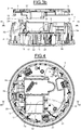
- the base 2 comprises a circular plate 4 and, at the periphery of this plate, an upper annular flange 5 projecting upwards and a lower annular flange 6 projecting downwards.
- the circular plate 4 has different openings 7 adapted for fixing it with screws and a large opening 8.
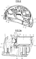
- the casing 3 is generally cylindrical in shape and comprises a rear or upper circular plate 9, a peripheral wall 9a and a front cover 9b.
- the box 3 has a recessed annular wall 10 facing downwards, discontinuous peripherally, and an upper annular flange 11 facing upwards and in the extension of the peripheral wall 9a, which determine between they have an annular groove 12 facing upwards.
- the upper circular plate 9 of the box 3 is intended to bear against the circular plate 4 of the base 2, the lower annular flange 6 of the base 2 then being engaged in the annular groove 12 of the box 3, so that the base 2 and the housing 3, in the support position, can rotate relative to each other being guided.
- the lower annular flange 6 of the base 2 and the casing 3, inside its annular groove 12, have pairs of stops 13 and 14, distributed peripherally, such that, in said support position, the base 2 and the box 3 may be rotated relative to each other between an engagement position and a mounted position.
- the lower annular flange 6 of the base 2 have inner hooks 15 distributed peripherally, able to engage below portions of the annular wall 10 of the box 3 when, in said support position, the base 2 and the box 3 leave said engagement position, in the direction of said mounted position, so as to maintain the box 3 on the base 2 in said mounted position relative to the other, a bayonet fitting thus being produced.
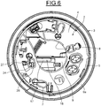
- the box 3 has, inside and below the annular plate 9, a compartment 16 open on the side of the lid 9b and accessible from the front of the box 3 when the lid 9b and the interior equipment of the box 3 are removed.
- the compartment 16 can be installed, horizontally, an electric battery 17, for example cylindrical, which has a front electrical contact pad 18 at one of its ends and a rear electrical contact pad 19 at its other end.
- the compartment 16 can be adapted to the shape of the electric battery 17. According to the example shown, the longitudinal axis of the electric battery 17 is offset relative to the center of the upper circular plate 9 of the box 3 and its front stud 18 is in the peripheral zone of the upper circular plate 9.
- the casing 3 is equipped with a front electrical contact member 20 and a rear electrical contact member 21 intended to be in contact with the front and rear electrical contact pads 18 and 19 of the electric cell.
- elastic contact 20 is formed by an elastic blade, slightly arched, and is fixed, cantilevered, on an electronic card 22 which extends parallel to the circular plate 9 and just in front of the compartment 16, the curved portion the front elastic contact member 20 being able to be elastically in contact with the electrical connection front stud 18 of the electric battery 17.
- the rear electrical contact member 21 is also connected to the electronic card 22.
- a second electric battery 17a can be installed in the compartment 16, next to the electric battery 17.
- a front electrical contact member with a front stud of the electric battery can be connected to the electronic card 22 and the rear pads of the batteries 17 and 17a can be connected by a bar for a series connection of the batteries 17 and 17a.
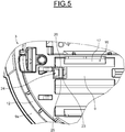
- the circular plate 9 of the box 3 has an opening 23, for example square, located in the area of the front stud 18 of the electric battery 17 and the front electrical contact member 20.
- the circular plate 9 of the box 3 is provided, in its opening 23 and in one piece, with an anti-assembly stop 24 which protrudes with respect to the outer face of the circular plate 9.
- This anti-stop -mounting 23 is weakly connected to two opposite edges of the opening 23 by opposite connecting branches 25 and 26 located on either side of the longitudinal axis of the electric cell 17.
- the circular plate 4 of the base 2 has an opening 27 placed such that, when the base 2 and the box 3 are in said engagement position, the anti-assembly stop 24 of the box 3 is engaged in this opening 25 and is adjacent to an edge of this opening 25 which forms a stop 28. These stops 24 and 28 cooperate to oppose the pivoting of the box 3 relative to the base 2 from said engagement position to said mounted position.
- the anti-assembly abutment 24 of the box 3 is provided, in one piece, with a blade 29 which extends inwardly of the box 3 substantially perpendicular to the circular plate 9 of this box 3.
- This blade 29 extends between the electrical contact front stud 18 of the electric cell 17 and the front electrical contact member 20, so as to electrically isolate this front stud 18 and this front member 20.
- the housing 1 can be used as follows.
- the base 2, the box 3 and the lid 9b are separately arranged.
- the casing 3 comprises, in one piece, the anti-assembly stop 24 and the insulating strip 29 arranged as described above.
- An electric battery 17 is installed in the compartment 16 and the electronic card 22 is installed so that the insulating strip 29 is interposed between the front electrical contact member 20 and the electrical contact front stud 18 of the electric battery 17 and that the rear electrical contact pad 19 of the electric battery 17 is in contact with the electrical contact member 21. Then, possibly other equipment is installed and the cover 9b is installed.
- Box 3 is then in the situation illustrated on the figures 3a , 3b and 4 to 6 .
- the battery 17 is electrically isolated and can not be discharged via the electronic card 22 which consequently is not supplied with electrical energy.
- the user couples the base 2 and the box 3 in said engagement position, it can not rotate the box 3 relative to the base 2 thanks to the presence of the anti-assembly stopper 24 of the box 3 which immediately come into contact with the anti-assembly stop 28 of the base ( figure 6 ).
- the user To make the housing 1 operational, the user must remove or remove the abutment and anti-contact member constituted by the anti-assembly stop 24 and the insulating blade 29, by breaking the connecting branches 25 and 26.
- the anti-assembly stop 24 may have a hole 24a ( figure 3a ) to receive the tip of a tool to facilitate its removal.
- the base 2 and the caisson 3 are released and, on the other hand, the front electrical contact member 20 is released and comes into contact with the electrical contact front stud 18 under the effect of its elasticity, so that the electronic card 22 is then powered by the battery 17.
- Box 2 is then in the situation shown on the Figures 7 and 8 .
- the box 2, with the equipment it contains, is then in operating condition.
- the anti-assembly abutment 24 is now absent, the user can then couple the base 2 and the box 3 in said engagement position.
- Box 2 is then in the situation shown on the figure 9 .
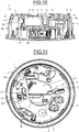
- the housing 1 is then in the final situation represented on the Figures 10 and 11 and is operational where the base has been previously fixed.
- the abutment and anti-contact member constituted by the anti-assembly abutment 24 and the insulating blade 29 which it carries constitutes, by its presence, a protective switch against a discharge of the battery 17 and holding power off the electronic card 21 and an anti-mounting means of the box 3 on the base 2 and, when removed, means for powering the electronic card 21 and a mechanical release means of the base 2 and the box 3 relative to each other for mounting one on the other.
- the abutment and anti-contact member constituted by the anti-assembly abutment 24 and the insulating blade 29 could form a single attached piece mounted on the circular plate 9 of the box 3. so as to be removable or withdrawable so that it can be retracted by the user to a retracted position, for example by sliding or tilting. In this retracted position, the anti-assembly abutment 24 would then be remote from the abutment 28 of the base 2 and the insulating strip 29 would be moved away from its insulation position described above.
- the housing 3 may be intended to contain in particular a smoke detector. Nevertheless, the anti-assembly abutment means 24 and 28 and the isolation blade 29 associated with the electric battery 17 and the electrical contact member 20 could be used in housings intended for all other uses, in particular in the field of alarm systems.
Landscapes
- Chemical & Material Sciences (AREA)
- Analytical Chemistry (AREA)
- Business, Economics & Management (AREA)
- Emergency Management (AREA)
- Physics & Mathematics (AREA)
- General Physics & Mathematics (AREA)
- Battery Mounting, Suspending (AREA)
- Fire-Detection Mechanisms (AREA)
Applications Claiming Priority (1)
| Application Number | Priority Date | Filing Date | Title |
|---|---|---|---|
| FR1152504A FR2973173B1 (fr) | 2011-03-25 | 2011-03-25 | Boitier a organe de butee et d'anti-contact |
Publications (2)
| Publication Number | Publication Date |
|---|---|
| EP2503526A1 true EP2503526A1 (de) | 2012-09-26 |
| EP2503526B1 EP2503526B1 (de) | 2014-07-16 |
Family
ID=45851438
Family Applications (1)
| Application Number | Title | Priority Date | Filing Date |
|---|---|---|---|
| EP12161068.7A Active EP2503526B1 (de) | 2011-03-25 | 2012-03-23 | Gehäuse mit Anschlag- und Anti-Kontaktorgan |
Country Status (3)
| Country | Link |
|---|---|
| EP (1) | EP2503526B1 (de) |
| ES (1) | ES2515719T3 (de) |
| FR (1) | FR2973173B1 (de) |
Cited By (2)
| Publication number | Priority date | Publication date | Assignee | Title |
|---|---|---|---|---|
| EP2804161A1 (de) | 2013-05-17 | 2014-11-19 | Hager Security | Kasten, der aus einem Sockel, einem Gehäuse und einem Drehorgan zum Zusammenbau besteht |
| CN112634573A (zh) * | 2020-12-09 | 2021-04-09 | 南京思达捷信息科技有限公司 | 一种用于智慧建筑的多功能的消防报警装置 |
Citations (5)
| Publication number | Priority date | Publication date | Assignee | Title |
|---|---|---|---|---|
| FR2648597A1 (fr) * | 1989-06-12 | 1990-12-21 | Pittway Corp | Mecanisme de detection de batterie |
| GB2241985A (en) * | 1990-03-09 | 1991-09-18 | Pittway Corp | Battery missing indicator for smoke detector cover |
| EP0714158A2 (de) * | 1994-11-23 | 1996-05-29 | Brk Brands, Inc. | Detektor mit langer Lebensdauer |
| US6433700B1 (en) * | 2001-02-15 | 2002-08-13 | Wojciech Marek Malewski | Multiuse on/off switch for hazard detector |
| WO2004082042A2 (en) * | 2003-03-10 | 2004-09-23 | Walter Kidde Portable Equipment, Inc. | Pivoting battery carrier and a life safety device incorporating the same |
Family Cites Families (3)
| Publication number | Priority date | Publication date | Assignee | Title |
|---|---|---|---|---|
| GB9906784D0 (en) * | 1999-03-25 | 1999-05-19 | Coventry University Enterprise | Detector |
| US7123158B2 (en) * | 2003-08-29 | 2006-10-17 | Walter Kidde Portable Equipment, Inc. | Life safety alarm with a sealed battery power supply |
| US20100073172A1 (en) * | 2008-09-25 | 2010-03-25 | L.I.F.E. Support Technologies, Llc | Dual condition fire/smoke detector with adjustable led cannon |
-
2011
- 2011-03-25 FR FR1152504A patent/FR2973173B1/fr active Active
-
2012
- 2012-03-23 ES ES12161068.7T patent/ES2515719T3/es active Active
- 2012-03-23 EP EP12161068.7A patent/EP2503526B1/de active Active
Patent Citations (5)
| Publication number | Priority date | Publication date | Assignee | Title |
|---|---|---|---|---|
| FR2648597A1 (fr) * | 1989-06-12 | 1990-12-21 | Pittway Corp | Mecanisme de detection de batterie |
| GB2241985A (en) * | 1990-03-09 | 1991-09-18 | Pittway Corp | Battery missing indicator for smoke detector cover |
| EP0714158A2 (de) * | 1994-11-23 | 1996-05-29 | Brk Brands, Inc. | Detektor mit langer Lebensdauer |
| US6433700B1 (en) * | 2001-02-15 | 2002-08-13 | Wojciech Marek Malewski | Multiuse on/off switch for hazard detector |
| WO2004082042A2 (en) * | 2003-03-10 | 2004-09-23 | Walter Kidde Portable Equipment, Inc. | Pivoting battery carrier and a life safety device incorporating the same |
Cited By (3)
| Publication number | Priority date | Publication date | Assignee | Title |
|---|---|---|---|---|
| EP2804161A1 (de) | 2013-05-17 | 2014-11-19 | Hager Security | Kasten, der aus einem Sockel, einem Gehäuse und einem Drehorgan zum Zusammenbau besteht |
| FR3005802A1 (fr) * | 2013-05-17 | 2014-11-21 | Hager Security | Coffret comprenant un socle, un boitier et un organe rotatif d'assemblage |
| CN112634573A (zh) * | 2020-12-09 | 2021-04-09 | 南京思达捷信息科技有限公司 | 一种用于智慧建筑的多功能的消防报警装置 |
Also Published As
| Publication number | Publication date |
|---|---|
| ES2515719T3 (es) | 2014-10-30 |
| FR2973173B1 (fr) | 2014-01-17 |
| EP2503526B1 (de) | 2014-07-16 |
| FR2973173A1 (fr) | 2012-09-28 |
Similar Documents
| Publication | Publication Date | Title |
|---|---|---|
| EP0246141A1 (de) | Gehäuse zum Vorzeigen oder zum Ordnen eines elektrischen Werkzeuges, insbesondere für eine kleine Bohrmaschine | |
| EP3231042A1 (de) | Stromsteckdosenvorrichtung mit mindestens einem verriegelungs- und entriegelungselement | |
| FR2875427A1 (fr) | Couteau de travail | |
| FR2930849A3 (fr) | Prise electrique multiple de securite. | |
| EP0617536B1 (de) | Tragbares und kompaktes Funkfernsprechgerät | |
| EP2503526B1 (de) | Gehäuse mit Anschlag- und Anti-Kontaktorgan | |
| EP3473532A1 (de) | System zum aufbewahren und laden von elektro-rollern, und station, die dieses umfasst | |
| WO2013160609A1 (fr) | Dispositif de decoupe d'aliments comportant un espace de rangement | |
| EP2780168A1 (de) | Vorrichtung zum laden einer walze für einen drucker in einem zahlungsendgerät | |
| FR3023964A1 (fr) | Ensemble de finition pour interrupteur electrique et interrupteur electrique avec un tel ensemble de finition | |
| FR2909167A1 (fr) | Dispositif de nivellement laser | |
| EP2503525B1 (de) | Gehäuse mit Anti-Montage-Finger auf Kontakt | |
| FR3036546A1 (fr) | Dispositif de recharge pour des telephones portables ou d'autres appareils electroniques portables similaires | |
| EP3018691B1 (de) | Auslöser für elektrische umschaltvorrichtung, und elektrische umschaltvorrichtung, die einen solchen auslöser umfasst | |
| EP3529867B1 (de) | Elektrisches gerät mit einer verriegelungsvorrichtung für eine montageschiene | |
| EP2045881B1 (de) | Einsteckbare Steckdose, die einen öffenbaren Steckkörper und einen mobilen, schwenkbaren Anschlussblock umfasst | |
| EP2527717B1 (de) | Vorrichtung zur elektrischen Stromversorgung einer tragbaren Lampe | |
| EP3975353A1 (de) | Elektrische stromverteilungsvorrichtung | |
| EP4154776B1 (de) | Küchenmaschinen-untergestell mit einem schwenkbaren sicherheitsverschluss | |
| FR3005794A1 (fr) | Accessoire de verrouillage d'une fiche electrique dans une prise de courant | |
| EP1834366B1 (de) | Batteriebetriebene einrichtung für einen stromzähler und stromzähler | |
| FR3004013A1 (fr) | Element amovible pour un appareillage modulaire electrique muni d'une poignee pivotante | |
| FR2965420A1 (fr) | Accessoire electrique monte mobile en translation dans une ouverture pratiquee dans une paroi | |
| EP2434599A1 (de) | Elektrisches verschiebbares Zubehör, das in eine Wandöffnung eingebaut ist | |
| EP4707953A1 (de) | Uhrengehäuse mit bajonettverbindung und schloss |
Legal Events
| Date | Code | Title | Description |
|---|---|---|---|
| PUAI | Public reference made under article 153(3) epc to a published international application that has entered the european phase |
Free format text: ORIGINAL CODE: 0009012 |
|
| AK | Designated contracting states |
Kind code of ref document: A1 Designated state(s): AL AT BE BG CH CY CZ DE DK EE ES FI FR GB GR HR HU IE IS IT LI LT LU LV MC MK MT NL NO PL PT RO RS SE SI SK SM TR |
|
| AX | Request for extension of the european patent |
Extension state: BA ME |
|
| 17P | Request for examination filed |
Effective date: 20130312 |
|
| 17Q | First examination report despatched |
Effective date: 20130524 |
|
| GRAP | Despatch of communication of intention to grant a patent |
Free format text: ORIGINAL CODE: EPIDOSNIGR1 |
|
| INTG | Intention to grant announced |
Effective date: 20140305 |
|
| GRAS | Grant fee paid |
Free format text: ORIGINAL CODE: EPIDOSNIGR3 |
|
| GRAA | (expected) grant |
Free format text: ORIGINAL CODE: 0009210 |
|
| AK | Designated contracting states |
Kind code of ref document: B1 Designated state(s): AL AT BE BG CH CY CZ DE DK EE ES FI FR GB GR HR HU IE IS IT LI LT LU LV MC MK MT NL NO PL PT RO RS SE SI SK SM TR |
|
| REG | Reference to a national code |
Ref country code: GB Ref legal event code: FG4D Free format text: NOT ENGLISH |
|
| REG | Reference to a national code |
Ref country code: CH Ref legal event code: EP |
|
| REG | Reference to a national code |
Ref country code: IE Ref legal event code: FG4D Free format text: LANGUAGE OF EP DOCUMENT: FRENCH |
|
| REG | Reference to a national code |
Ref country code: AT Ref legal event code: REF Ref document number: 678034 Country of ref document: AT Kind code of ref document: T Effective date: 20140815 |
|
| REG | Reference to a national code |
Ref country code: DE Ref legal event code: R096 Ref document number: 602012002393 Country of ref document: DE Effective date: 20140828 |
|
| REG | Reference to a national code |
Ref country code: ES Ref legal event code: FG2A Ref document number: 2515719 Country of ref document: ES Kind code of ref document: T3 Effective date: 20141030 |
|
| REG | Reference to a national code |
Ref country code: NL Ref legal event code: VDEP Effective date: 20140716 |
|
| REG | Reference to a national code |
Ref country code: AT Ref legal event code: MK05 Ref document number: 678034 Country of ref document: AT Kind code of ref document: T Effective date: 20140716 |
|
| REG | Reference to a national code |
Ref country code: LT Ref legal event code: MG4D |
|
| PG25 | Lapsed in a contracting state [announced via postgrant information from national office to epo] |
Ref country code: FI Free format text: LAPSE BECAUSE OF FAILURE TO SUBMIT A TRANSLATION OF THE DESCRIPTION OR TO PAY THE FEE WITHIN THE PRESCRIBED TIME-LIMIT Effective date: 20140716 Ref country code: PT Free format text: LAPSE BECAUSE OF FAILURE TO SUBMIT A TRANSLATION OF THE DESCRIPTION OR TO PAY THE FEE WITHIN THE PRESCRIBED TIME-LIMIT Effective date: 20141117 Ref country code: NO Free format text: LAPSE BECAUSE OF FAILURE TO SUBMIT A TRANSLATION OF THE DESCRIPTION OR TO PAY THE FEE WITHIN THE PRESCRIBED TIME-LIMIT Effective date: 20141016 Ref country code: BG Free format text: LAPSE BECAUSE OF FAILURE TO SUBMIT A TRANSLATION OF THE DESCRIPTION OR TO PAY THE FEE WITHIN THE PRESCRIBED TIME-LIMIT Effective date: 20141016 Ref country code: LT Free format text: LAPSE BECAUSE OF FAILURE TO SUBMIT A TRANSLATION OF THE DESCRIPTION OR TO PAY THE FEE WITHIN THE PRESCRIBED TIME-LIMIT Effective date: 20140716 Ref country code: GR Free format text: LAPSE BECAUSE OF FAILURE TO SUBMIT A TRANSLATION OF THE DESCRIPTION OR TO PAY THE FEE WITHIN THE PRESCRIBED TIME-LIMIT Effective date: 20141017 Ref country code: SE Free format text: LAPSE BECAUSE OF FAILURE TO SUBMIT A TRANSLATION OF THE DESCRIPTION OR TO PAY THE FEE WITHIN THE PRESCRIBED TIME-LIMIT Effective date: 20140716 |
|
| PG25 | Lapsed in a contracting state [announced via postgrant information from national office to epo] |
Ref country code: RS Free format text: LAPSE BECAUSE OF FAILURE TO SUBMIT A TRANSLATION OF THE DESCRIPTION OR TO PAY THE FEE WITHIN THE PRESCRIBED TIME-LIMIT Effective date: 20140716 Ref country code: IS Free format text: LAPSE BECAUSE OF FAILURE TO SUBMIT A TRANSLATION OF THE DESCRIPTION OR TO PAY THE FEE WITHIN THE PRESCRIBED TIME-LIMIT Effective date: 20141116 Ref country code: LV Free format text: LAPSE BECAUSE OF FAILURE TO SUBMIT A TRANSLATION OF THE DESCRIPTION OR TO PAY THE FEE WITHIN THE PRESCRIBED TIME-LIMIT Effective date: 20140716 Ref country code: CY Free format text: LAPSE BECAUSE OF FAILURE TO SUBMIT A TRANSLATION OF THE DESCRIPTION OR TO PAY THE FEE WITHIN THE PRESCRIBED TIME-LIMIT Effective date: 20140716 Ref country code: NL Free format text: LAPSE BECAUSE OF FAILURE TO SUBMIT A TRANSLATION OF THE DESCRIPTION OR TO PAY THE FEE WITHIN THE PRESCRIBED TIME-LIMIT Effective date: 20140716 Ref country code: PL Free format text: LAPSE BECAUSE OF FAILURE TO SUBMIT A TRANSLATION OF THE DESCRIPTION OR TO PAY THE FEE WITHIN THE PRESCRIBED TIME-LIMIT Effective date: 20140716 Ref country code: AT Free format text: LAPSE BECAUSE OF FAILURE TO SUBMIT A TRANSLATION OF THE DESCRIPTION OR TO PAY THE FEE WITHIN THE PRESCRIBED TIME-LIMIT Effective date: 20140716 |
|
| REG | Reference to a national code |
Ref country code: DE Ref legal event code: R097 Ref document number: 602012002393 Country of ref document: DE |
|
| PG25 | Lapsed in a contracting state [announced via postgrant information from national office to epo] |
Ref country code: CZ Free format text: LAPSE BECAUSE OF FAILURE TO SUBMIT A TRANSLATION OF THE DESCRIPTION OR TO PAY THE FEE WITHIN THE PRESCRIBED TIME-LIMIT Effective date: 20140716 Ref country code: DK Free format text: LAPSE BECAUSE OF FAILURE TO SUBMIT A TRANSLATION OF THE DESCRIPTION OR TO PAY THE FEE WITHIN THE PRESCRIBED TIME-LIMIT Effective date: 20140716 Ref country code: RO Free format text: LAPSE BECAUSE OF FAILURE TO SUBMIT A TRANSLATION OF THE DESCRIPTION OR TO PAY THE FEE WITHIN THE PRESCRIBED TIME-LIMIT Effective date: 20140716 Ref country code: EE Free format text: LAPSE BECAUSE OF FAILURE TO SUBMIT A TRANSLATION OF THE DESCRIPTION OR TO PAY THE FEE WITHIN THE PRESCRIBED TIME-LIMIT Effective date: 20140716 Ref country code: SK Free format text: LAPSE BECAUSE OF FAILURE TO SUBMIT A TRANSLATION OF THE DESCRIPTION OR TO PAY THE FEE WITHIN THE PRESCRIBED TIME-LIMIT Effective date: 20140716 |
|
| PLBE | No opposition filed within time limit |
Free format text: ORIGINAL CODE: 0009261 |
|
| STAA | Information on the status of an ep patent application or granted ep patent |
Free format text: STATUS: NO OPPOSITION FILED WITHIN TIME LIMIT |
|
| 26N | No opposition filed |
Effective date: 20150417 |
|
| PG25 | Lapsed in a contracting state [announced via postgrant information from national office to epo] |
Ref country code: MC Free format text: LAPSE BECAUSE OF FAILURE TO SUBMIT A TRANSLATION OF THE DESCRIPTION OR TO PAY THE FEE WITHIN THE PRESCRIBED TIME-LIMIT Effective date: 20140716 Ref country code: LU Free format text: LAPSE BECAUSE OF FAILURE TO SUBMIT A TRANSLATION OF THE DESCRIPTION OR TO PAY THE FEE WITHIN THE PRESCRIBED TIME-LIMIT Effective date: 20150323 |
|
| REG | Reference to a national code |
Ref country code: CH Ref legal event code: PL |
|
| PG25 | Lapsed in a contracting state [announced via postgrant information from national office to epo] |
Ref country code: SI Free format text: LAPSE BECAUSE OF FAILURE TO SUBMIT A TRANSLATION OF THE DESCRIPTION OR TO PAY THE FEE WITHIN THE PRESCRIBED TIME-LIMIT Effective date: 20140716 |
|
| REG | Reference to a national code |
Ref country code: IE Ref legal event code: MM4A |
|
| REG | Reference to a national code |
Ref country code: FR Ref legal event code: PLFP Year of fee payment: 5 |
|
| PG25 | Lapsed in a contracting state [announced via postgrant information from national office to epo] |
Ref country code: IE Free format text: LAPSE BECAUSE OF NON-PAYMENT OF DUE FEES Effective date: 20150323 Ref country code: CH Free format text: LAPSE BECAUSE OF NON-PAYMENT OF DUE FEES Effective date: 20150331 Ref country code: LI Free format text: LAPSE BECAUSE OF NON-PAYMENT OF DUE FEES Effective date: 20150331 |
|
| PG25 | Lapsed in a contracting state [announced via postgrant information from national office to epo] |
Ref country code: MT Free format text: LAPSE BECAUSE OF FAILURE TO SUBMIT A TRANSLATION OF THE DESCRIPTION OR TO PAY THE FEE WITHIN THE PRESCRIBED TIME-LIMIT Effective date: 20140716 |
|
| REG | Reference to a national code |
Ref country code: FR Ref legal event code: PLFP Year of fee payment: 6 |
|
| PG25 | Lapsed in a contracting state [announced via postgrant information from national office to epo] |
Ref country code: HU Free format text: LAPSE BECAUSE OF FAILURE TO SUBMIT A TRANSLATION OF THE DESCRIPTION OR TO PAY THE FEE WITHIN THE PRESCRIBED TIME-LIMIT; INVALID AB INITIO Effective date: 20120323 Ref country code: SM Free format text: LAPSE BECAUSE OF FAILURE TO SUBMIT A TRANSLATION OF THE DESCRIPTION OR TO PAY THE FEE WITHIN THE PRESCRIBED TIME-LIMIT Effective date: 20140716 |
|
| PG25 | Lapsed in a contracting state [announced via postgrant information from national office to epo] |
Ref country code: HR Free format text: LAPSE BECAUSE OF FAILURE TO SUBMIT A TRANSLATION OF THE DESCRIPTION OR TO PAY THE FEE WITHIN THE PRESCRIBED TIME-LIMIT Effective date: 20140716 Ref country code: BE Free format text: LAPSE BECAUSE OF NON-PAYMENT OF DUE FEES Effective date: 20150331 |
|
| PG25 | Lapsed in a contracting state [announced via postgrant information from national office to epo] |
Ref country code: TR Free format text: LAPSE BECAUSE OF FAILURE TO SUBMIT A TRANSLATION OF THE DESCRIPTION OR TO PAY THE FEE WITHIN THE PRESCRIBED TIME-LIMIT Effective date: 20140716 |
|
| REG | Reference to a national code |
Ref country code: FR Ref legal event code: PLFP Year of fee payment: 7 |
|
| PG25 | Lapsed in a contracting state [announced via postgrant information from national office to epo] |
Ref country code: MK Free format text: LAPSE BECAUSE OF FAILURE TO SUBMIT A TRANSLATION OF THE DESCRIPTION OR TO PAY THE FEE WITHIN THE PRESCRIBED TIME-LIMIT Effective date: 20140716 |
|
| PG25 | Lapsed in a contracting state [announced via postgrant information from national office to epo] |
Ref country code: AL Free format text: LAPSE BECAUSE OF FAILURE TO SUBMIT A TRANSLATION OF THE DESCRIPTION OR TO PAY THE FEE WITHIN THE PRESCRIBED TIME-LIMIT Effective date: 20140716 |
|
| PGFP | Annual fee paid to national office [announced via postgrant information from national office to epo] |
Ref country code: GB Payment date: 20230327 Year of fee payment: 12 |
|
| REG | Reference to a national code |
Ref country code: DE Ref legal event code: R082 Ref document number: 602012002393 Country of ref document: DE Representative=s name: CASALONGA & PARTNERS PATENTANWAELTE - AVOCATS, DE |
|
| GBPC | Gb: european patent ceased through non-payment of renewal fee |
Effective date: 20240323 |
|
| PG25 | Lapsed in a contracting state [announced via postgrant information from national office to epo] |
Ref country code: GB Free format text: LAPSE BECAUSE OF NON-PAYMENT OF DUE FEES Effective date: 20240323 |
|
| PG25 | Lapsed in a contracting state [announced via postgrant information from national office to epo] |
Ref country code: GB Free format text: LAPSE BECAUSE OF NON-PAYMENT OF DUE FEES Effective date: 20240323 |
|
| PGFP | Annual fee paid to national office [announced via postgrant information from national office to epo] |
Ref country code: DE Payment date: 20250313 Year of fee payment: 14 |
|
| PGFP | Annual fee paid to national office [announced via postgrant information from national office to epo] |
Ref country code: ES Payment date: 20250410 Year of fee payment: 14 |
|
| PGFP | Annual fee paid to national office [announced via postgrant information from national office to epo] |
Ref country code: IT Payment date: 20260320 Year of fee payment: 15 |
|
| PGFP | Annual fee paid to national office [announced via postgrant information from national office to epo] |
Ref country code: FR Payment date: 20260331 Year of fee payment: 15 |