EP2503330A2 - Multicapillary device for sample preparation - Google Patents
Multicapillary device for sample preparation Download PDFInfo
- Publication number
- EP2503330A2 EP2503330A2 EP12173003A EP12173003A EP2503330A2 EP 2503330 A2 EP2503330 A2 EP 2503330A2 EP 12173003 A EP12173003 A EP 12173003A EP 12173003 A EP12173003 A EP 12173003A EP 2503330 A2 EP2503330 A2 EP 2503330A2
- Authority
- EP
- European Patent Office
- Prior art keywords
- multicapillary
- sample preparation
- preparation device
- sample
- stationary phase
- Prior art date
- Legal status (The legal status is an assumption and is not a legal conclusion. Google has not performed a legal analysis and makes no representation as to the accuracy of the status listed.)
- Withdrawn
Links
Images


Classifications
-
- B—PERFORMING OPERATIONS; TRANSPORTING
- B01—PHYSICAL OR CHEMICAL PROCESSES OR APPARATUS IN GENERAL
- B01L—CHEMICAL OR PHYSICAL LABORATORY APPARATUS FOR GENERAL USE
- B01L3/00—Containers or dishes for laboratory use, e.g. laboratory glassware; Droppers
- B01L3/02—Burettes; Pipettes
- B01L3/0275—Interchangeable or disposable dispensing tips
-
- G—PHYSICS
- G01—MEASURING; TESTING
- G01N—INVESTIGATING OR ANALYSING MATERIALS BY DETERMINING THEIR CHEMICAL OR PHYSICAL PROPERTIES
- G01N30/00—Investigating or analysing materials by separation into components using adsorption, absorption or similar phenomena or using ion-exchange, e.g. chromatography or field flow fractionation
- G01N30/02—Column chromatography
- G01N30/04—Preparation or injection of sample to be analysed
- G01N30/06—Preparation
-
- G—PHYSICS
- G01—MEASURING; TESTING
- G01N—INVESTIGATING OR ANALYSING MATERIALS BY DETERMINING THEIR CHEMICAL OR PHYSICAL PROPERTIES
- G01N30/00—Investigating or analysing materials by separation into components using adsorption, absorption or similar phenomena or using ion-exchange, e.g. chromatography or field flow fractionation
- G01N30/02—Column chromatography
- G01N30/26—Conditioning of the fluid carrier; Flow patterns
- G01N30/38—Flow patterns
- G01N30/46—Flow patterns using more than one column
- G01N30/466—Flow patterns using more than one column with separation columns in parallel
- G01N30/467—Flow patterns using more than one column with separation columns in parallel all columns being identical
-
- G—PHYSICS
- G01—MEASURING; TESTING
- G01N—INVESTIGATING OR ANALYSING MATERIALS BY DETERMINING THEIR CHEMICAL OR PHYSICAL PROPERTIES
- G01N30/00—Investigating or analysing materials by separation into components using adsorption, absorption or similar phenomena or using ion-exchange, e.g. chromatography or field flow fractionation
- G01N30/02—Column chromatography
- G01N30/60—Construction of the column
- G01N30/6034—Construction of the column joining multiple columns
- G01N30/6043—Construction of the column joining multiple columns in parallel
-
- G—PHYSICS
- G01—MEASURING; TESTING
- G01N—INVESTIGATING OR ANALYSING MATERIALS BY DETERMINING THEIR CHEMICAL OR PHYSICAL PROPERTIES
- G01N30/00—Investigating or analysing materials by separation into components using adsorption, absorption or similar phenomena or using ion-exchange, e.g. chromatography or field flow fractionation
- G01N30/02—Column chromatography
- G01N30/60—Construction of the column
- G01N30/6052—Construction of the column body
- G01N30/6073—Construction of the column body in open tubular form
- G01N30/6078—Capillaries
-
- B—PERFORMING OPERATIONS; TRANSPORTING
- B01—PHYSICAL OR CHEMICAL PROCESSES OR APPARATUS IN GENERAL
- B01L—CHEMICAL OR PHYSICAL LABORATORY APPARATUS FOR GENERAL USE
- B01L2200/00—Solutions for specific problems relating to chemical or physical laboratory apparatus
- B01L2200/06—Fluid handling related problems
- B01L2200/0631—Purification arrangements, e.g. solid phase extraction [SPE]
-
- B—PERFORMING OPERATIONS; TRANSPORTING
- B01—PHYSICAL OR CHEMICAL PROCESSES OR APPARATUS IN GENERAL
- B01L—CHEMICAL OR PHYSICAL LABORATORY APPARATUS FOR GENERAL USE
- B01L2300/00—Additional constructional details
- B01L2300/08—Geometry, shape and general structure
- B01L2300/0832—Geometry, shape and general structure cylindrical, tube shaped
- B01L2300/0838—Capillaries
-
- B—PERFORMING OPERATIONS; TRANSPORTING
- B01—PHYSICAL OR CHEMICAL PROCESSES OR APPARATUS IN GENERAL
- B01L—CHEMICAL OR PHYSICAL LABORATORY APPARATUS FOR GENERAL USE
- B01L3/00—Containers or dishes for laboratory use, e.g. laboratory glassware; Droppers
- B01L3/50—Containers for the purpose of retaining a material to be analysed, e.g. test tubes
- B01L3/508—Containers for the purpose of retaining a material to be analysed, e.g. test tubes rigid containers not provided for above
- B01L3/5085—Containers for the purpose of retaining a material to be analysed, e.g. test tubes rigid containers not provided for above for multiple samples, e.g. microtitration plates
- B01L3/50857—Containers for the purpose of retaining a material to be analysed, e.g. test tubes rigid containers not provided for above for multiple samples, e.g. microtitration plates using arrays or bundles of open capillaries for holding samples
-
- G—PHYSICS
- G01—MEASURING; TESTING
- G01N—INVESTIGATING OR ANALYSING MATERIALS BY DETERMINING THEIR CHEMICAL OR PHYSICAL PROPERTIES
- G01N30/00—Investigating or analysing materials by separation into components using adsorption, absorption or similar phenomena or using ion-exchange, e.g. chromatography or field flow fractionation
- G01N30/02—Column chromatography
- G01N30/04—Preparation or injection of sample to be analysed
- G01N30/06—Preparation
- G01N30/14—Preparation by elimination of some components
- G01N2030/143—Preparation by elimination of some components selective absorption
-
- G—PHYSICS
- G01—MEASURING; TESTING
- G01N—INVESTIGATING OR ANALYSING MATERIALS BY DETERMINING THEIR CHEMICAL OR PHYSICAL PROPERTIES
- G01N35/00—Automatic analysis not limited to methods or materials provided for in any single one of groups G01N1/00 - G01N33/00; Handling materials therefor
- G01N35/10—Devices for transferring samples or any liquids to, in, or from, the analysis apparatus, e.g. suction devices, injection devices
- G01N2035/1027—General features of the devices
- G01N2035/1048—General features of the devices using the transfer device for another function
- G01N2035/1053—General features of the devices using the transfer device for another function for separating part of the liquid, e.g. filters, extraction phase
-
- G—PHYSICS
- G01—MEASURING; TESTING
- G01N—INVESTIGATING OR ANALYSING MATERIALS BY DETERMINING THEIR CHEMICAL OR PHYSICAL PROPERTIES
- G01N30/00—Investigating or analysing materials by separation into components using adsorption, absorption or similar phenomena or using ion-exchange, e.g. chromatography or field flow fractionation
- G01N30/02—Column chromatography
- G01N30/04—Preparation or injection of sample to be analysed
- G01N30/06—Preparation
- G01N30/08—Preparation using an enricher
Landscapes
- Chemical & Material Sciences (AREA)
- Health & Medical Sciences (AREA)
- General Health & Medical Sciences (AREA)
- Life Sciences & Earth Sciences (AREA)
- Analytical Chemistry (AREA)
- Biochemistry (AREA)
- Physics & Mathematics (AREA)
- General Physics & Mathematics (AREA)
- Immunology (AREA)
- Pathology (AREA)
- Clinical Laboratory Science (AREA)
- Chemical Kinetics & Catalysis (AREA)
- Devices For Use In Laboratory Experiments (AREA)
- Sampling And Sample Adjustment (AREA)
- Apparatus Associated With Microorganisms And Enzymes (AREA)
Abstract
Description
- This application claims benefit of
U.S. Patent Application No. 10/955,377 filed September 30, 2004 U.S. Provisional Patent Application No. 60/507,474 filed September 30, 2003 - The present invention relates to a multicapillary sample preparation device especially useful for handling biological samples. In particular, the multicapillary device is suitable for use with a pipette, micropipette, syringe, or other similar analytical instrument.
- Many biological samples are commonly separated by gel electrophoresis and analyzed by matrix assisted laser desorpition/ionization mass spectrometry (MALDI-MS). One disadvantage of these techniques, however, is that analysis is strongly affected by the presence of salts, buffers and low molecular weight organic compounds commonly used in the preparation of biological samples. In order to improve the sensitivity and selectivity of analyses, adsorptive and membranous devices are frequently used to purify and concentrate the sample prior to analysis. Such devices feature a bed of porous adsorbent or a semipermeable membrane fixed in a housing of a suitable dimension and shape that traps' desired constituents, while allowing contaminants to pass.
- To handle samples in the 0.01 to 100 microgram (µg) range, pipettes, micropipettes, syringes or similar analytical instruments (collectively referred to hereinafter as "pipettes") are commonly employed. The tip of these pipettes is fitted with one or more adsorptive or membranous plugs capable of purifying, concentrating, or fractionating peptides and other biomolecules.
- A principal shortcoming of adsorptive and membranous plugs, however, is that porous materials are generally not effective at separating smaller biomolecules such as proteins and polynucleotides. Porous plugs are also deficient with respect to isolating and purifying larger biological materials and nucleic acids such as DNA, RNA and cells. This shortcoming derives from the fact that during sample processing, molecules must wend through a labyrinth of sponge-like, expansive and porous adsorbent silica.
- There is little uniformity, consistency, and reproducibility of porous materials used for sample preparation. Sample loss in existing pipette tips is typically about 40-60%. Poor sample recovery is largely due to the fact that a sample must travel through irregular voids in the porous material, whereby a portion of the sample lodges in small voids and is unrecoverable. Moreover, in order to achieve adequate results, samples must be passed through porous materials multiple times (e.g., ten). The sample preparation devices are usually not reusable and fit poorly with automatic instrumentation because poor sample recovery may give rise to contamination due to sample carry-over.
- Spin columns and other apparatus operated by a centrifuge rotor are commonly used for the isolation and purification of biological and nucleic acid samples. However, it is desirable in certain applications to avoid the use of a centrifuge for rotating a specimen to be isolated and purified. This is due, in part, to the fact that horizontal separation may result in centrifugal forces of up to, for example, 4,000 RPM, being exerted on or transmitted along the vertical axis of the spin column and sample in order to achieve satisfactory separation. Air resistance negatively affects the spin column by generating drag and friction, which heat the spin column and its contents. Considerable breakage of sample fragments is unavoidable due to the heat transfer, acute centrifugal force and accompanying air resistance. The impaired quality of biological and nucleic acid samples extracted during spin column and centrifugal processing is highly undesirable to the user.
- It can be seen, therefore, that the purification and concentration of biological and nucleic acid samples using porous materials prior to instrumental analysis is time consuming, is poorly reproducible, has low throughput, and requires repeated passing of a sample through the porous plug.
- Accordingly, it is an object of the present invention to provide an efficient sample preparation device for use in isolating (immunoassay), purifying and concentrating samples of proteins, peptides, nucleic acids (e.g., DNA and RNA), and other biological materials (e.g., cells) prior to analysis.
- It is also an object of the invention to provide a sample preparation device with high sample capacity that increases throughput and reduces sample loss.
- It is a further object of the invention to provide a highly reproducible sample preparation device that achieves uniformity, consistency, and nearly identical pathways for sample passage.
- It is a still further object of the invention to provide a sample preparation device that is simple, cost-effective, and does not require the use of a silica type porous substrate or special equipment such as a centrifuge.
- The invention is a high surface area multicapillary sample preparation device especially useful for handling biological samples. The multicapillary device does not require use of a silica type porous substrate. Rather, the device incorporates a plurality of parallel capillary tubes, wherein the cavity of each tube remains open and unobstructed throughout sample processing. The capillary tubes of the device function independently of one another so that sample molecules are incapable of being physically exchanged or diffusing from one capillary to another. The multicapillary device is preferably disposed in a housing that is suitable for attachment to a "pipette" or other sample preparation or analytical instrument, enabling the isolation, purification, concentration and/or fractionation of nucleic acids or biological samples in the micro- and nanoliter range, as well as larger mass loads and volumes. In an embodiment of the invention, the multicapillary device features a monolithic element pierced with multiple uniform capillaries. The monolithic element is typically mounted in the lower end of a pipette tip, syringe needle or tubing, and is operated using a pipette.
- For protein separation and purification applications, an insoluble stationary phase material is deposited onto the interior surfaces (walls) of each capillary tube, without employing a supporting or intermediary constituent.
- The invention also includes a method of preparing a multicapillary device for protein sample preparation. In such method, inner walls of the capillary tubes are first coated with a stationary phase material, and then the monolithic element is mounted in an appropriate housing. Alternatively, the monolithic element can first be fixed in a housing, after which the capillary walls can be coated with the stationary phase. For operation, the multicapillary sample preparation device is attached to a pipette, micropipette, tube, syringe or similar analytical instrument.
-
-
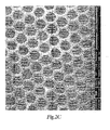
FIG. 1 is a perspective view of a multicapillary device for sample preparation in accordance with an embodiment of the present invention. Individual capillaries of the device are shown in the enlarged, cross-sectional views ofFIGS. 2A ,2C and2D (SEM).Figure 2B is an exploded, perspective view of an individual capillary tube. -
FIG. 3 depicts SEM images showing cross-sectional views of a conventional sample preparation device. -
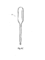
FIGS. 4A-4D are perspective views of pipette tips and a pipette format multicapillary device, respectively, in accordance with the present invention. -
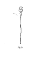
FIGS. 5A-5C show perspective views of a syringe format multicapillary device for sample preparation according to the present invention. -
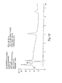
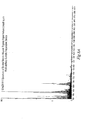
FIG. 6 is a chromatogram showing the separation of a three component mixture in a multicapillary device for sample preparation according to the present invention. -
FIG. 7A is a chromatogram illustrating the performance of a multicapillary sample preparation device in sample enrichment as compared to a standard SPE cartridge,FIG. 7 B. -
FIGS. 8A and8B are mass spectra demonstrating the performance of a multicapillary sample preparation device in desalting of complex peptide mixtures. -
FIGS. 9A and 9B are mass spectra demonstrating the performance of a multicapillary sample preparation device in fractionating of complex peptide mixtures. -
FIG. 10 shows gels demonstrating sample capacity and recovery performance (10A), reproducibility (10B), and time performance (10C) of a conventional device versus a multicapillary sample preparation device according to the present invention. Comparative data is shown in Table 2. -
FIG. 11A is a perspective view of a conventional spin column used for DNA purification.FIGS. 11B and11C are SEM images of the spin column. -
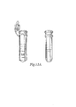
FIGS. 12A and12B , respectively, show pulsed field and agarose gel electrophoresis analyses performed to determine DNA quality and size of a conventional spin column versus a multicapillary sample preparation device according to the present invention. -
FIGS. 13A and 13B , respectively, show sample purification results of conventional spin columns versus a multicapillary sample preparation device of the present invention in terms of DNA yield and time required for sample preparation - In accordance with the present invention, a parallel capillary array or multicapillary
sample preparation device 12 is provided for use with commercially available pipettes to permit the isolation, purification, concentration and/or fractionation of biological samples in the micro- and nanoliter range, as well as larger mass loads and volumes. The invention includes both detachable and integrally embeddedmulticapillary devices 12 adapted for use with manual and automatic pipettes,micropipettes 20,syringes 22 and other sample handling or analytical instruments. Notably, themulticapillary device 12 does not require use of a silica type porous substrate. - Referring now to
FIGS. 1 and2 , there is shown a multicapillary device forsample preparation 12 comprising a monolithic element (rod, tube, etc.) 14 that has an upper end and a lower end, and defines a chamber.Capillary tubes 16 of uniform internal diameter and length are arranged within the chamber. Eachcapillary tube 16 includes a non-porous or imperforate wall having an inner and an outer surface, which defines an inner bore. Eachtube 16 also includes a first and a second opening at opposing ends, so that resistance and backpressure are low. - For protein or peptide separation and purification applications, it is preferable to deposit an insoluble
stationary phase 18 on imperforate inner walls of thecapillary tubes 16. For the separation and purification of polar compounds such as nucleic acids (e.g., DNA and RNA), it is preferable that the insolublestationary phase 18 comprise a polar material. In a preferred embodiment of the invention, the thickness of thestationary phase 18 is correlated with the radius of individualcapillary tubes 16 to optimize efficiency of themulticapillary device 12. As a result, during application of thestationary phase 18, a greater amount settles on the inner surface of wider capillaries; while a smaller amount settles on the inner surface of narrower capillaries. Through this process, thecapillaries 16 achieve quasi-uniformity, which substantially increases the efficiency of themulticapillary device 12. The following relationship for high, peak efficiency has been derived by the inventors:
- The stationary phase film thickness df is proportional to capillary radius r in power n, where n > 1; cf is a constant.
- In a more preferred embodiment, the thickness of the
stationary phase coating 18 is proportional to the radius of thecapillary tubes 16 in power n, where n is greater than 1. - To achieve the highest peak efficiency, the stationary phase thickness df is proportional to capillary radius r in
power 3. -
Stationary phase media 18 is retained on the interior surfaces of the imperforate,hollow capillary tubes 16 via stable chemical bonding or cross-linking. There is, therefore, no discharge ofstationary phase media 18 into the mobile phase during separation, reducing sample contamination. In the open tubular system of themulticapillary device 12, supporting intermediary constituents and adsorptive and membranous plugs (e.g., porous adsorbent silica particles or fibers) are unnecessary. The lumen or inner cavity of eachcapillary tube 16 remains unobstructed and impediment free throughout the protein, peptide, nucleic acid or biological sample separation process. In this stable, surface-mediated mechanism of separation, sample molecules are incapable of diffusing between and through the imperforate walls of thecapillary tubes 16 or from one capillary to another.Individual capillary tubes 16 remain physically and functionally independent of one another. - The multicapillary device for
sample preparation 12 may be detachably mounted (mechanically) or fixedly inserted (e.g., by melting or adhesion) about the end portion of a pipette tip, needle, tubing or other housing of suitable shape and dimension that is attachable to apipette 20. Themulticapillary device 12 receives a sample in a mobile (liquid) phase at its first end, and a concentrated and purified sample, devoid of contaminants such as salts and buffers, is discharged at a second end of thedevice 12. - As shown in
FIGS. 2A, 2B and2C (Scanning Electron Microscope image), the structure of themulticapillary device 12 is distinctive and dissimilar to conventional spin columns and silica-based adsorptive and membranous "plugs" (seeFIGS. 3 and11 ), which feature irregular voids and vastly different sample pathways that entrap biological samples, such that more than half of the sample is usually unrecoverable. Themulticapillary device 12 comprises a plurality of uniformcapillary tubes 16 having an insolublestationary phase media 18 on internal surfaces thereof, thereby permitting a sample inserted into the flow passage of themulticapillary device 12 to advance through open and virtually identical pathways. The inner cavity or flow passage of eachcapillary tube 16 thus remains unobstructed and impediment free throughout the sample separation process. - As shown in
FIGS. 12 and13 , purified (DNA) sample fragments extracted from the open and unobstructed capillary channels of themulticapillary device 12 comprise considerably larger fragments, representing a significant decrease in fragment breakage or "shearing." These larger fragments generally reflect a better quality of purified sample as compared to conventional porous silica plugs used for sample processing. In the conventional adsorptive and membranous plugs, sample must travel through tortuous and irregular voids in the porous material, whereby portions of the sample lodge in small voids and are unrecoverable. Fragment shearing is thus unavoidable. With its open and unobstructed channel structure, themulticapillary device 12 of the present invention achieves substantial uniformity and consistency as compared to the sponge-like and expansive porous silica materials currently used for sample preparation. - Due to the significant reduction in sample loss enabled by the open and unobstructed channel structure of the
multicapillary device 12, it is unnecessary for sample to be passed through the separation materials multiple times, as required in existing porous silica plugs, particles (for proteins and peptides), and fibers (for DNA and RNA). As a result, themulticapillary device 12 is generally reusable and fits conveniently with automatic instrumentation because there is no contamination due to sample carry-over. In short, thepresent multicapillary device 12 demonstrates superior characteristics over conventional adsorptive and membranous plugs with respect to binding capacity, recovery, increased throughput, uniformity and reproducibility. - In one embodiment of the invention, the imperforate inner walls of the
capillary tubes 16 include particles of inert material or a nodular or uneven surface for increasing the surface area of themulticapillary device 12. In such case, the inner wall may be altered using an etching process in combination with a solvent such as, for example, a mineral acid or base, or an organic acid or base. - The present invention encompasses the use of any
stationary phase 18 and surface chemistry adapted for liquid chromatography and sample preparation applications. In some embodiments, thestationary phase media 18 deposited on inner surfaces of the capillary wall comprises a monolayer of organic molecules, biopolymers or larger particles- Such molecules and particles include, but are not limited to, hydrocarbons and their C-, N-, S-, and P-derivatives; proteins, nucleic acids, and polysaccharides; linear and cross-linked polysiloxanes and other polymers; and viruses and cells. In other embodiments, astationary phase coating 18 is formed by treating inner surfaces of thecapillaries 16 with organosilicone compounds and further modifying these groups with appropriate reagents and particles. - An alternative technique for the deposition of a
stationary phase 18 involves polymerization of unsaturated compounds, such as butadiene, styrene, divinylbenzene, and others, on inner walls of thecapillary tubes 16. - The techniques used for deposition of a
stationary phase material 18, described in the following Examples, render the stationary phase material insoluble in organic and water-organic solvents commonly used in sample preparation and liquid chromatography, such as acetonitrile, methanol, isopropanol, acetone, dimethylsulfoxide, dimethylformamide and urea; acetic, iodoacetic, trifluoroacetic and formic acids; and phosphate, acetic and carbonate buffers, etc. - The multicapillary
sample preparation device 12 is advantageously suited for use with a wide range of sample preparation and analytical instruments. As shown inFIGS. 1 ,4 , and5 , these include, but are not limited to, manual and automatic pipettes andmicropipettes 20,syringes 22, disposable devices, and automatic sample handling instruments. In some embodiments, themulticapillary device 12 is inserted about the terminal portion of apipette tip 20 or other appropriate housing by, for example, sliding or press fitting, and is detachably retained in place by mechanical means such as elastic sealing rings and/or walls of the housing. - In other embodiments, the
multicapillary device 12 is integrally and permanently embedded (e.g., cast-in-place) about the terminal region of apipette tip 20 or other housing by melting, heat shrinking or adhesion in order to fuse themonolithic element 14 to the surface of apipette tip 20 or other housing commonly made from polypropylene or other thermoplastic material. As an alternative, plasma and/or chemical means may be used to accomplish adhesion of themonolithic element 14 to the surface of thepipette tip 20 or other housing. - In yet another embodiment, the
multicapillary device 12 is adapted to be detachably or fixedly engaged or aligned with the hollow flow passage(s) of a substantially cylindrical, conical or other housing configuration. Themulticapillary device 12 is suitably sized and shaped to be integrated in housings of varying sizes and configurations. However, it is preferable that the housing have a volume in the range of about 0.1 µL to about 100 mL, more preferably in the range of about 1 to about 1000 µL, and most preferably in the range of about 2 to about 200 µL. - It will be understood that any technique used to install the
multicapillary device 12 into a pipette tip or other housing for operation with apipette 20 should accurately direct sample in a liquid phase through thecapillary tubes 16 of themonolithic element 14 without-bypassing theelement 14. In such adaptation, themulticapillary device 12 receives the sample at its first end, and a concentrated and/or purified sample, devoid of contaminants such as salts and buffers, is discharged at a second end. Themulticapillary device 12 of the present invention is freely permeable not only to proteins, peptides, polynucleotides, and other molecules and biopolymers, but also to viruses, spores, cells (e.g., cancer and stem), and microorganisms. It will be understood, however, that sample molecules are prevented from diffusing from onecapillary tube 16 to another - Preferred materials for fabricating the
monolithic element 14,capillary tubes 16, tips, pipettes 20,syringes 22 and other housings of the present invention include, but are not limited to, glass, fused silica, ceramic, metal (e.g., stainless steel), and plastic (e.g., polypropylene, polyethylene, polyolefin, or polyetheretherketone). In sample preparation and chromatographic applications, it is desirable to employ a large number (e.g. hundreds or thousands) of capillary tubes to provide an abundant surface area for higher sample loading capacity. It will be understood, however, that the number and dimensions of themulticapillary device 12,stationary phase media 18, solvent, tips and other housings employed in the invention will vary according to application. - As an example, the number of
capillary tubes 16 provided in amulticapillary device 12 may range from about 100 to about 1,000,000. The inner diameter of eachcapillary tube 16 may range from about 0.1µm to about 200µm. The outer diameter of themonolithic element 14 may range from about 0.1 mm to about 1 m, and the length may range from about 0.1 mm to about 2 m. In a preferred embodiment, the number ofcapillary tubes 16 ranges from about 1000 to about 10,000, the inner diameter of each capillary ranges from about 5 µm to about 100 µm, the outer diameter of themonolithic element 14 ranges from about 1 mm to about 20 mm, and the length ranges from about 1 mm to about 250 mm. - A 5% solution of trimethylchlorosilane in toluene is pumped at 10 µL/min for six-hours through a 1 mm outer diameter × 250 mm long multicapillary glass rod pierced with approximately 4400 capillaries of 10 µm diameter at 105°C. The multicapillary rod is rinsed with toluene, acetone and methanol, and dried with a nitrogen stream.
- A 10% solution of butyldimethylchlorosilane in toluene is pumped at 40 µL/min for six hours through a 2 mm outer diameter × 300 mm long multicapillary glass rod pierced with approximately 4600 capillaries of 25 µm diameter at 105°C. The multicapillary rod is rinsed with toluene, acetone and methanol, and dried with a nitrogen stream.
- A. 10% solution of octyltrichlorosilane in toluene is pumped at 50 µL/min for six hours through a 2.3 mm outer diameter × 250 mm long multicapillary glass rod pierced with approximately 1400 capillaries of 40 µm diameter at 105°C. The multicapillary rod is rinsed with toluene, acetone and methanol, and dried with a nitrogen stream.
- A 5% solution of dodecyltrichlorosilane in toluene is pumped at 75 µL/min for six hours through a 6 mm outer diameter × 300 mm long multicapillary glass rod pierced with approximately 3300 capillaries of 65 µm diameter at 105°C. The multicapillary rod is rinsed with toluene, acetone and methanol, and dried with a nitrogen stream.
- A 10% solution of octadecylethoxysilane in toluene is pumped at 10 µL/min for six hours through a clean and dry 2.3 mm outer diameter × 300 mm multicapillary glass rod-pierced with approximately 4,000 capillaries of 20 yn diameter at 105°C. While pumping the solution, all opposite end of the multicapillary device is moved at a linear speed of 0.5 mm/min inside an oven heated to 150°C. The device is rinsed with toluene, acetone and methanol, and dried with a nitrogen stream.
- Twenty 1 mm outer diameter × 2.5 mm long multicapillary glass rods pierced with approximately 4400 capillaries of 10 µm diameter are placed in a flask containing 50 mL of a 5% solution of octadecyldimethylchlorosilane in toluene and equipped with a reflux condenser and a calcium chloride tube. The mixture is slowly refluxed for six hours. The liquid phase is separated and the multicapillary rods are repeatedly washed with toluene, tetrahydrofuran and methanol, and dried at room temperature.
- In accordance with the conditions described in Example 6, the stationary phases with C-16, C-30, phenyl, naphthyl and cyano groups are prepared, correspondingly, from hexadecyltrichlorosilane, triacontyltrichlorosilane, phenethyltrichlorosilane, (1-naphthylmethyl)trichlorosilane and 3-cyanopropyltrichlorosilane.
- Twenty 2.3 mm outer diameter × 5 mm long multicapillary glass rods pierced with approximately 1400 capillaries of 40 µm diameter are placed in a flask containing 50 mL of a 5% solution of (3-glycidoxylpropyl)trimethoxysilane in toluene and equipped with a reflux condenser. The mixture is slowly refluxed for five hours while the condenser is maintained at a temperature of 70°C to remove the methanol formed from the reaction. The liquid phase is separated and the multicapillary rods are repeatedly washed with toluene, tetrahydrofuran and methanol, and dried at room temperature.
- Twenty 2.3 mm outer diameter × 3 mm long multicapillary glass rods pierced with approximately 1400 capillaries of 40 µm diameter are placed in a flask containing 50 mL of a 5% solution of (3-glycidoxypropyl)trimethoxysilane in toluene and equipped with a reflux condenser. The mixture is slowly refluxed for three hours while the condenser is maintained at a temperature of 70°C. The liquid phase is separated and the multicapillary rods are repeatedly washed with toluene, tetrahydrofuran, methanol and water. 50 mL of water is added and the pH is adjusted to 2.0 with nitric acid. The mixture is slowly agitated for two hours at room temperature. The liquid phase is separated and the multicapillary rods are washed with water until the wash is neutral, then washed three times with methanol, and dried at room temperature.
- 2.5 g of (3-glycidoxypropyl)trimethoxysilane is dropped into a flask containing 50 mL of water, while maintaining the pH between 5 and 6 with 0.01 M potassium hydroxide. Twenty 2.3 mm outer diameter × 5 mm long multicapillary glass rods pierced with approximately 1400 capillaries of 40 µm diameter are placed in a flask. The mixture is slowly refluxed for three hours with a reflux condenser. The liquid phase is separated and the multicapillary rods are repeatedly washed with water, methanol and tetrahydrofuran. 50 mL of water is added and the pH is adjusted to 2.0 with nitric acid. The mixture is slowly agitated for two hours at room temperature. The liquid phase is separated and the multicapillary rods are washed with water until the wash is neutral, then washed three times with methanol, and dried at room temperature.
- Twenty-five 1 mm outer diameter × 2.5 mm long multicapillary glass rods pierced with approximately 4400 capillaries of 10 µm diameter are placed in a flask containing 50 mL of a 5% solution of 3-aminopropyltrimethoxysilane in toluene and equipped with a reflux condenser. The mixture is slowly refluxed for five hours while the condenser is maintained at a temperature of 70°C. The liquid phase is separated and the multicapillary rods are repeatedly washed with toluene, tetrahydrofuran and methanol, and dried at room temperature.
- Thirty 2.3 mm outer diameter × 5 mm long multicapillary glass rods pierced with approximately 1400 capillaries of 40 µm diameter are placed in a flask containing 50 mL of a 5% solution of 3-aminopropyltrimethoxysilane in toluene and equipped with a reflux condenser. The mixture is slowly refluxed for six hours while the condenser is maintained at a temperature of 70°C. The liquid phase is separated and the multicapillary rods are repeatedly washed with toluene, tetrahydrofuran and methanol. 30 mL of a 5% solution of trimethylamine in methanol is added to the flask. The flask is equipped with a calcium chloride tube, and the mixture is slowly agitated at 0-5°C for 48 hours. The liquid phase is separated and the multicapillary rods are repeatedly washed with methanol, water, 0.01 M HCl, water and tetrahydrofuran, and dried at room temperature.
- Twenty 2.3 mm outer diameter × 5 mm long multicapillary glass rods pierced with approximately 1400 capillaries of 40 µm diameter are placed in a flask containing 50 mL of a 5% water solution of carboxyethylsilane triol (sodium salt). The pH is adjusted to 2.0 by adding hydrochloric acid. The mixture is slowly refluxed for three hours with a reflux condenser. The liquid phase is separated and the multicapillary rods are washed with water until the wash is neutral, then washed three times with methanol, and dried at room temperature.
- Twenty-five 2.3 mm outer diameter × 3 mm long multicapillary glass rods pierced with approximately 1400 capillaries of 40 µm diameter are placed in a flask containing 50 mL of a 5% water solution of 3-(trihydroxysilyl)-1-propanesulfonic acid. The mixture is slowly refluxed for three hours with a reflux condenser. The liquid phase is separated and the multicapillary rods are washed with water until the wash is neutral, then washed three times with methanol, and dried at room temperature.
- Thirty 2.3 mm outer diameter × 3 mm long multicapillary glass rods pierced with approximately 1400 capillaries of 40 µm diameter are placed in a flask containing 50 mL of a 5% water solution of (3-trihydroxysilylpropyl)methylphosphonate sodium salt. The mixture is acidified to pH 2.0 with HCL and slowly refluxed for three hours with a reflux condenser. The liquid phase is separated and the multicapillary rods are washed with water until the wash is neutral, then washed three times with methanol, and dried at room temperature.
- Twenty 1 mm outer diameter × 2.5 mm long multicapillary glass rods pierced with approximately 4400 capillaries of 10 µm diameter are placed in a flask containing 50 mL of a 5% solution of (3-glycidoxypropyl)trimethoxysilane in toluene and equipped with a reflux condenser. The mixture is slowly refluxed for five hours while the condenser is maintained at a temperature of 70°C. The liquid phase is separated and the multicapillary rods are repeatedly washed with toluene, tetrahydrofuran, methanol and water. 20 mL of a 2 M iminodiacetic acid solution in 0.1 M sodium borate buffer, pH 8.5, is added and the mixture is slowly agitated for 24 hours at room temperature. The liquid phase is separated and the multicapillary rods are washed with water until the wash is neutral, then washed three times with methanol, and dried at room temperature.
- Twenty-five 1 mm outer diameter × 2.5 mm long multicapillary glass rods pierced with approximately 4400 capillaries of 10 µm diameter are placed in a flask containing 50 mL of a 5% solution of 3-bromopropyltrimethoxysilane in toluene and equipped with a reflux condenser. The mixture is slowly refluxed for five hours while the condenser is maintained at a temperature of 70°C. The liquid phase is separated and the multicapillary rods are repeatedly washed with toluene, tetrahydrofuran and methanol. 50 mL of a 1% solution of cystein in methanol and 1 mL of triethylamine are added, and the mixture is slowly refluxed with a reflux condenser for five hours. The liquid phase is separated and the multicapillary rods are repeatedly washed with methanol, water, methanol and methylene chloride, and dried at room temperature.
- Twenty 1 mm outer diameter × 2.5 mm long multicapillary glass rods pierced with approximately 4400 capillaries of 10 µm diameter are placed in a flask containing 50 mL of a 5% solution of 11-bromoundecyltrimethoxysilane in toluene and equipped with a reflux condenser. The mixture is slowly refluxed for five hours while the condenser is maintained at a temperature of 70°C. The liquid phase is separated and the multicapillary rods are repeatedly washed with toluene, tetrahydrofuran and methanol. 50 mL of a 0.5% solution of glutathione in methanol and 1 mL of triethylamine are added, and the mixture is slowly refluxed with a reflux condenser for five hours. The liquid phase is separated and the multicapillary rods are repeatedly washed with methanol, water, methanol and methylene chloride, and dried at room temperature.
- A 5% solution of (R)-N-1-phenylethyl-N'-triethoxysilylpropylurea in toluene is pumped at 10 µL/min for six hours through a 1 mm outer diameter × 300 mm long multicapillary glass rod pierced with approximately 4000 capillaries of 10 µm diameter at 105°C. The multicapillary rod is rinsed with toluene, tetrahydrofuran and methanol, and dried with a nitrogen stream.
- The 10% solution of vinyltrichlorosilane in isooctane is pumped at 20 µL/min for six hours through a 1 mm outer diameter × 250 mm long multicapillary glass rod pierced with approximately 4,400 capillaries of 10 µm diameter at 90°C. The multicapillary rod is rinsed with isooctane, tetrahydrofuran, methanol, toluene and isooctane. A solution of 100 mg polybutadiene (MW 3,400) and 0.5 mg dicumyl peroxide in 100 mL of isooctane is pumped at 10 µL/min for six hours through the multicapillary rod at 90°C. The multicapillary rod is rinsed with toluene, tetrahydrofuran and methanol, and dried with a nitrogen stream.
- Twenty five 1 mm outer diameter × 2.5 mm long multicapillary glass rods pierced with approximately 4400 capillaries of 10 µmdiameter are placed in a flask containing 50 mL of a 5% solution of 3-aminopropyltrimethoxysilane in toluene and equipped with a reflux condenser. The mixture is slowly refluxed for five hours while the condenser is maintained at a temperature of 70°C. The liquid phase is separated and the multicapillary rods are repeatedly washed with toluene, methanol and dimethylformamide. 15 mL of a saturated dimethylformamide solution of biotin, a solution of 0.3g of 1-hydroxybenzotriazole hydrate in 10 mL of dimethylformamide, and a solution of 0.25g of N, N'- dicyclohehylcarbodiimide in 10 mL of dimethylformamide are added, and the mixture is slowly agitated for five hours at room temperature. The liquid phase is separated and the multicapillary rods are repeatedly washed with dimethylformamide, methanol, water, methanol and methylene chloride, and dried at room temperature.
- Twenty 2.3 mm outer diameter × 2.5 mm long multicapillary glass rods pierced with approximately 1400 capillaries of 40 µm diameter are placed in a flask containing 50 mL of a 5% solution of 3-aminopropyltrimethoxysilane in toluene and equipped with a reflux condenser. The mixture is slowly refluxed for five hours while the condenser is maintained at a temperature of 70°C. The liquid phase is separated and the multicapillary rods are repeatedly washed with toluene, methanol, water and 0.05 M 2-morpholinoethane sulfonic acid buffer, pH 5.6. The 10 mL solution of 0.2g heparin (from bovine kidney), 1g N-(3-dimethylaminopropyl)-N'-ethylcarbodiimide, and 0.5g N-hydroxysuccinimide in 0.05 M 2-morpholinoethane sulfonic acid buffer, pH 5.6, is added. The mixture is slowly agitated for three hours at room temperature. The liquid phase is separated, and the multicapillary rods are repeatedly washed with water, phosphate buffer,
pH - Twenty 2.3 mm outer diameter × 3 mm long multicapillary glass rods pierced with approximately 1400 capillaries of 40 µm diameter are placed in a flask containing 20 mL of a 5% solution of (3-glycidoxypropyl)trimethoxysilane in toluene and equipped with a reflux condenser. The mixture is slowly refluxed for five hours while the condenser is maintained at a temperature of 70°C. The liquid phase is separated and the multicapillary rods are repeatedly washed with toluene, methanol and water. The 4 mL solution of 100 mg alphal1 acid (from bovine plasma) in a 1:1 mixture of 0.4 M sodium chloride and 0.2 M borate buffer, pH 8.5, is added. The mixture is slowly agitated at room temperature for 48 hours. The liquid phase is separated. The multicapillary rods are repeatedly washed with a 1:1 mixture of 0.4 M sodium chloride and 0.2 M borate buffer, pH 8.5, then washed with water and stored at 4°C.
- Twenty 2 mm outer diameter × 5 mm long multicapillary glass rods pierced with approximately 4600 capillaries of 25 µm diameter are placed in a flask containing 20 mL of a 5% solution of (3-glycidoxypropyl)trimethoxysilane in toluene and equipped with a reflux condenser. The mixture is slowly refluxed for five hours while the condenser is maintained at a temperature of 70°C. The liquid phase is separated and the multicapillary rods are repeatedly washed with toluene, methanol and water. A 7 mL solution of 100 mg trypsin (from bovine pancreas) in 0.2 M phosphate buffer, pH 7.0, is added to the flask. The mixture is slowly agitated at room temperature for 15 hours, and the liquid phase is separated. The multicapillary rods are repeatedly washed with 0.2 M phosphate buffer, pH 7.0, water, 0.2 M Tris buffer, pH 7.5, for two hours, and then washed with water and stored at 4°C.
- In accordance with the conditions described in Example 24, avidin, lectin and protein A stationary phases are prepared using avidin (from egg white), lectin (from Agaricus bisporus), and protein A (from Staphylococcus aureus), correspondingly.
- Twenty 2.3 mm outer diameter × 3 mm long multicapillary glass rods pierced with approximately 1400 capillaries of 40 µm diameter are placed in a flask containing 50 mL of a 5% solution of 10-(carbomethoxy)decyldimethylmethoxysilane in toluene and equipped with a reflux condenser. The mixture is slowly refluxed for three hours while the condenser is maintained at a temperature of 70°C. The liquid phase is separated, and the multicapillary rods are repeatedly washed with toluene, methanol and methylene chloride. A 35 mL solution of 1 mL trimethyliodosilane in methylene chloride is added. The mixture is slowly agitated for 72 hours at room temperature.
- The liquid phase is separated and the multicapillary rods are repeatedly washed with methylene chloride, methanol, 90% methanol and water. 20 mL of 0.02 M ethyl(dimethylaminopropyl)-carbodiimide in 0.1 M 2-morpholinoethanesulfonic acid buffer, pH 4.5, is added, and the mixture is slowly agitated for one hour at room temperature. The liquid phase is separated, and 5 mL of the 5 µg/mL solution of ricin antibody in 0.1 M phosphate buffered saline, pH 7.2, is added. The mixture is slowly agitated for two hours at room temperature. The liquid phase is separated. The multicapillary rods are repeatedly washed with phosphate buffered saline, pH 7.2, then washed with water and stored at 4°C.
- A 1 mm to 5 mm outer
diameter multicapillary element 10, prepared as described in Example 6, is tightly pushed to the lower end of apolypropylene 10 µL, to 5,000 µL volume micropipette tip. The lower portion of the pipette tip is placed for ten minutes in an oven thermostated at a temperature at which polypropylene begins to soften. Polypropylene pipette tip format multicapillary devices forsample preparation FIGS. 4A and 4B . - A 1 mm to 5 mm outer
diameter multicapillary element 10, prepared as described in Example 6, is tightly placed in the lower end of a disposable polyethylene transfer pipette. The lower portion of the pipette is placed for ten minutes in an oven thermostated at a temperature at which polyethylene begins to soften. A polyethylene pipette format multicapillary device forsample preparation FIG. 4C . - A 2 mm outer
diameter multicapillary element 10, prepared as described in Example 5, is attached to a heat shrinkable tubing. A removable syringe needle is attached to the second end of the heat shrinkable tubing. The heat shrinkable tubing zone is heated at a temperature recommended for the shrinkable tubing for ten minutes A representative syringe format multicapillary device forsample preparation FIG. 5A . - A 2.3 mm outer
diameter multicapillary element 10, prepared as described in Example 5, is tightly placed in a removable thermoplastic syringe hub. The hub is heated for ten minutes in an oven thermostated at a temperature at which thermoplastic begins to soften. Syringe format multicapillary devices forsample preparation FIGS. 5B and 5C . - A three component mixture (uracil, fluorene, and phenanthrene) is separated on the multicapillary device for sample preparation prepared as described in Example 5 and installed on a model LC-600 Shimadzu liquid chromatographic instrument using standard HPLC fittings. The chromatographic conditions and chromatogram are reproduced in
FIG. 6 . The chromatogram shows a uracil peak at about 1.8 minutes, a fluorene peak at about 2.1 minutes, and a phenanthrene peak at about 2.4 minutes. The example illustrates a liquid chromatographic application using the multicapillary device for sample preparation of the present invention, which enables a typical organic mixture to be analyzed in less than three minutes. - Referring to
FIG. 7A , a 2.3 mm outer diameter × 100 mm length multicapillary C-18 device for sample preparation containing approximately 1,400 capillaries of 40 µm diameter prepared as described in Example 5 is used for sample enrichment prior to HPLC analysis. At present, short HPLC columns known as solid phase extraction ("SPE") cartridges are commonly used for sample preparation. Compared to SPE cartridges, multicapillary devices forsample preparation 12 are much faster, simpler and reusable. Performance of the present multicapillary device for sample preparation 12 (FIG. 7A ) as compared to a standard SPE cartridge (FIG. 7B ) is shown in Table 1.Table 1. Multicapillary Device vs. Conventional SPE Cartridge. Characteristics SPE Cartridge Multicapillary Device 1 Collection time 20 - 40 minutes 1 - 5 minutes 2 Amount 1 - 5 ml samples 100 - 200 µl samples 3 Processing the extract Extract volume 5 - 20 ml Requires evaporation for analysis No concentration or evaporation of the extract required 4 Reconditioning Cannot be reconditioned Reconditioned by washing with methanol and water for 2 min. 5 Reusability Cannot be reused Can be reused at least 50 - 100 times depending on the sample to be extracted 6 Silica particles in the sample Fine silica particles in the samples No silica or other particles in the samples 7 Auto samplers adaptability Cannot be used in auto samplers Easily adaptable to auto samplers 8 Field use Difficult to transport Costly equipment/ accessories Requires only syringes - A 10 µL volume of 0.25 mg/mL bovine serum albumin solution in a 40:60 mixture of acetonitrile and 0.2 mM ammonium bicarbonate, pH 7.5, is aspirated in the multicapillary sample preparation device, prepared as described in Example 24, and thermostated at 37°C. After five minutes, the digested sample is dispensed in a vial and stored at 4°C.
- The bovine serum albumin digest, prepared as described in Example 34, is dried with a nitrogen stream and dissolved in 10 µL of 0.1% trifluoroacetic acid (TFA) in water. 1 µL of this sample is aspirated and dispensed from the multicapillary sample preparation device, as described in Examples 5 and 27. Three 10 µL portions of 0.1% trifluoroacetic acid (TFA) in 5% acetonitrile/water are pumped in and out of the multicapillary sample preparation device. The sample is eluted from the multicapillary sample preparation device with a 5 µL portion of 0.1% TFA in 70% acetonitrile/water and analyzed by MALDI-MS. The MALDI-MS spectra of the sample before and after desalting are shown in
FIGS. 8A and8B . - A 3 µL volume of the 100 pmole/µL peptide mixture obtained by the enzymatic hydrolysis of bovine serum albumin, as described in Example 34, is introduced into a 10 cm long C-18 multicapillary sample preparation device. The sample is eluted at 100 µL/min with 100 µL of 0.1% TFA in water followed by 30 µL of 0.1% TFA in 40% acetonitrile/water. Ten 3 µL 40% acetonitrile/water fractions are collected and analyzed by MALDI-MS. The mass-spectra of
fractions FIGS. 9A and 9B . This example illustrates the fractionating ability of the multicapillary sample preparation device of the present invention, prior to MALDI-MS analysis of a complex peptide mixture. -
FIGS. 10A and10B depict gels produced to evaluate the sample capacity, recovery, and reproducibility of a multicapillary device for sample preparation according to the present invention, as compared to commercially available porous silica-based devices.Lanes Lanes 2 to 5 represent the conventional devices, whileLanes 3 to 10 denote the multicapillary sample preparation device of the instant invention. - The test sample used for electrophoresis is a mixture of the following four representative proteins: Phosphorylase B (MW 97,400), Bovine Serum Albumin (MW 66,200), Carbonic Anhydrase (MW 31,000), and Lysozyme (MW 14,400). These proteins were selected due to their varying size and generally known properties. Moreover, these proteins are commonly used as standards. All results were reproduced and retested several times to ensure accuracy. Testing was conducted at ChromBA, Inc. (State College, PA), The Materials Research Institute (University Park, PA), The Milton Hershey Medical Center (Hershey, PA), Huck Institute (University Park, PA), APD LifeSciences Inc. (State College, PA), and MassTech Inc. (Columbia, MD). In total, over 40 gels were used, including both C18 and C4, the two most popular phases on the market. In addition, more than 500 sample preparation devices were tested.
- In both figures, the conventional silica-based devices (
FIG. 10A : Lanes 2-5;FIG.10B : Lanes 1-2) show faint and varying bands. In contrast, the device of the present invention (FIG. 10A : Lanes 6-9;FIG. 10B : Lanes 3-10) shows bold and dark bands, indicating vastly superior binding capacity, and recovery. Moreover, the bands of the present device are clearly more identical from lane to lane demonstrating superior reproducibility. As shown in Table 2, further quantification reveals that the sample preparation device of the present invention, on average, binds and releases nearly twice the protein bound and released by conventional devices, and demonstrates half the margin of error (i.e., variance in amount of sample bound).Table 2. Sample Capacity, Recovery Performance, and Reproducibility of Multicapillary Device vs. Conventional Devices. PROTEIN MEAN VALUE OF BAND INTENSITY % OF INCREASED CAPACITY AVERAGE MARGIN OF ERROR Convent. Device Multicap. Device Multicap. Device Convent. Device Multicap. Device FIG. 10A Phosphorylase B 45,7 56,2 23% 5.8% 3.4% Bovine Serum Albumin 85,2 162,1 91 % Carbonic Anhydrase 86,8 131,4 51 % Lysozyme 84,2 151,6 79% FIG. 10B Phosphorylase B - - - - - Bovine Serum Albumin 85,5 135,1 107% 6.3% 3.8 % Carbonic Anhydrase 70,1 108,6 55 % Lysozyme 77,0 157,6 104% -
FIG. 10C shows a gel produced to evaluate the speed of use (time performance) of a multicapillary device for sample preparation according to the present invention relative to commercially available silica-based devices. As recommended by the manufacturers, a sample must be passed through the tip of the silica-based devices approximately ten times to achieve suitable results. This is largely due to the fact that most of the sample travels through large voids in the filtration material and is subsequently not adsorbed and cleaned. Specifically, as illustrated by Lanes 1-4 ofFIG. 10C , the conventional devices show faint bands even after ten passes through the tip. - In contrast, Lanes 5-10 show nearly identical spots for samples passed through the multicapillary device of the present invention only once. Notably, the bands are much darker and broader than those of the silica-based devices, denoting the presence of vastly greater amounts of protein.
- In
FIGS. 10A-10C, the darkness and size of the bands on the gels developed by electrophoresis indicate the amount of protein bound by and recovered from the sample preparation devices; namely, pipette tips with integral silica-based plugs versus multicapillary elements. The superior performance of themulticapillary device 12 of the present invention is due, in part, to the uniform, consistent and virtually identical pathways for sample passage through the device, along with excellent tip-to-tip duplication, as shown inFIG. 2 .FIG. 3 andFIG. 11 , in contrast, depict cross-sections of commercially available (market leader) porous silica and silica fiber based sample preparation devices. The silica based devices reveal irregular particle sizes and fiber diameter, large voids (dark areas), and vastly different sample pathways. Moreover, the conventional devices demonstrate poor tip-to-tip duplication (i.e., tremendous variance). - The following experiments, featuring both
syringe 22 andpipette tip 20format multicapillary devices 12, demonstrate the advantage of using a multicapillary device for sample handling and extraction of DNA from various biological samples, such as tissue, blood, bacterial cells, urine, etc. - A multicapillary device for sample preparation 12 (1 to 2.5 mm outer diameter, 0.25 to 3 cm long, approximately 4000 capillaries of 10 to 40 µm diameter,
inner volume 2 to 90 µL) is loaded twice with 10 to 1,000 µL lysed biological sample. After discarding the loading solution, themulticapillary device 12 is rinsed with a washing buffer to dispose of proteins and other non-DNA type materials. Adsorbed DNA is then eluted with 10 to 300 µL elution buffer. The eluted DNA is analyzed using a variety of methods including Yo-Pro fluorescence on a Packard FluoroCount instrument at 530 nm (for yield determination), Agarose gel electrophoresis (for quality determination), and pulsed field gel electrophoresis (for DNA size and quality determination). -
FIGS. 13A and 13B , respectively, are bar graphs comparing 16 rat liver samples' purification results in terms of DNA yield and time required for sample preparation using 25 µm × 1 cm × 200 µL pipette tipformat multicapillary devices multicapillary devices 12 of the present invention are comparable to conventional spin columns in terms of DNA yield, but require significantly less time for processing. Notably, use of the present multicapillary devices results in a seven-fold decrease in "hands-on" labor time for DNA isolation sample preparation. - Agarose gel electrophoresis and pulsed field gel electrophoresis analyses were performed to determine DNA quality and size.
FIG. 12B shows a 0.8% agarose gel run to analyze DNA extracted from whole bovine blood using the pipette tip format multicapillary devices (Lanes 1-7) and commercially available spin columns (Lanes 8-9), demonstrating comparable DNA yields and quality. Further, as shown inFIG. 12A , pulsed field gel electrophoresis was used to size DNA strands of purified samples using themulticapillary device 12 of the present invention and commercially available spin columns. As compared to the leading spin columns, samples extracted using thepresent multicapillary device 12 demonstrate considerably larger DNA fragments, which suggests a significant decrease in DNA breakage or "shearing" during sample processing. Larger fragments of DNA reflect a better quality of the purified sample, which is highly desirable for many downstream applications such as PCR and sequencing. - As demonstrated in
FIGS. 12 and13 , significant DNA shearing is unavoidable in specimens processed using the commercially available spin columns, which are operated by means of a centrifuge. In themulticapillary device 12 of the present invention, however, DNA shearing is largely avoided through the use of an insoluble, surface-mediated mechanism of separation, which ensures that capillary channels (lumens) remain open and unobstructed throughout sample processing. Use of a gentle pipetting procedure for sample processing, in lieu of the commonly employed centrifuge, further contributes to the quality and size of DNA processed by means of themulticapillary devices 12 disclosed herein. - Table 3 shows the adsorbance reading of five
multicapillary devices 12 prepared according to the method described above. The average DNA recovery yield is 50-60%, which demonstrates that the multicapillary device forsample preparation 12 is efficacious for sample handling, purification and isolation of nucleic acids.Table 3. DNA Isolation on Multicapillary Device. Sample Fluorescence Reading (Units) Blank elution buffer 21 Elution buffer spiked with 16µg/mL DNA 214 Eluted DNA from MC 211 Eluted DNA from MC 211 Eluted DNA from MC 217 Eluted DNA from MC 238 Eluted DNA from MC 213 - To demonstrate the use of a
multicapillary device 12 for sample handling of cells, the following cells are grown and evaluated: mouse myeloma Sp210-Ag14, approximately 25 µm size; mouse macrophage J774A1, approximately 15 µm size; and human prostrate tumor THP-1 approximately 20 µm size. A syringe format multicapillary device forsample preparation 12, 22 (2.3 mm outer diameter, 150 mm long, approximately 1400 capillaries of 40 µm diameter, inner volume 262 µL) is attached to a syringe and rinsed with 1 mL of balanced salt solution creating an environment conductive to cell viability. At room temperature, a 1.5-3.0 mL volume of cell suspension is passed through the multicapillary device at a flow rate of 1 mL/min, followed by a 0.5 mL volume of balanced salt solution. The eluted cell suspension is concentrated by centrifugation and cells are counted using a hemacytometer. The change in cell viability after passage through the multicapillary device is presented in Table 4.Table 4. Cell Viability Upon Passage Through Multicapillary Device. Cell Suspension Volume Concentration of Cells Viable Cells Initial Viable Cells Recovered % Viably Cells Recovered Sp2/0-Ag14 3.0 mL 1×10⁶ cells/mL 2.73×10⁶ 2.09×10⁶ 76.5 J774A1 2.0 mL 3.5×10⁶ cells/mL 6.30×10⁶ 3.57×10⁶ 56.6 THP-1 2.0 mL 3.5×10⁶ cells/mL 6.65×10⁶ 5.06×10⁶ 76.1 - The data reveal that the vast majority of each cell type passed through the device emerges unharmed. Therefore, the multicapillary device for sample preparation is highly efficacious for sample handling of cells.
- Manufacturers of existing pipette tips state in their technical literature that 40-60% sample loss is average for a purified product In comparison, the increased capacity and recovery afforded by the present invention substantially reduces and/or eliminates the critical problem of sample loss in the pipette tip. Moreover, equipment wear is reduced, since the present invention eschews repeat sample passage, as required by conventional silica-based devices.
- As demonstrated by the foregoing Examples 1-38, the
multicapillary device 12 of the present invention enables a user to achieve superior sample preparation results in significantly less time. Indeed, the device's 12 ability to return quality results quickly and reproducibly permits a user to increase the throughput of available sample preparation stations at least several times, depending upon the sample and system employed. - In short, the multicapillary
sample preparation device 12 of the present invention advantageously increases sample throughput and decreases variance in a highly reproducible fashion. Themulticapillary device 12 may be used in an array of applications without departing from the scope of the invention. These include, but are not limited to, sample handling of small molecules, polymers, viruses and cells; the isolation, purification, concentration, desalting and fractionation of biological samples and nucleic acids, including DNA and RNA; solid phase extraction; head space analysis; gas chromatography; liquid chromatography (e.g., HPLC); supercritical chromatography; electrochromatography; and capillary electrophoresis. - Representative examples of the above-mentioned applications include: sample preparation of biological samples such as proteins, peptides, and polynucleotides, fractionation of peptide mixtures prior to mass-spectrometric analysis, desalting of samples prior to instrumental analysis, desalting of peptide solutions, desalting of protein solutions, sample concentration prior to instrumental analysis, and peptide concentration prior to mass-spectrometric analysis.
- While the invention has been particularly shown and described with reference to the examples and preferred embodiments thereof, it will be understood by those skilled in the art that various alterations in form and detail may be made therein without departing from the spirit and scope of the invention.
- The invention also relates to the following aspects as defined in the following numbered paragraphs:
- 1. A sample preparation device, especially useful for handling biological samples, comprising:
- (a) an element for receiving a sample at an upper end thereof and discharging a concentrated, purified, or separated sample at a lower end of the element, said element defining a cavity;
- (b) a plurality of capillary tubes arranged within said cavity, each capillary tube defining an inner bore having an inner wall and first and second openings; and
- (c) a housing of substantially cylindrical or conical configuration for retaining the multicapillary element, said housing being suitable for attachment to a sample preparation or analytical instrument.
- 2. The sample preparation device of
paragraph 1 wherein a stationary phase is deposited on the inner wall of said capillary tubes without an intermediary constituent. - 3. The sample preparation device of
paragraph 2 wherein the inner bore of said capillary tubes is unobstructed by said stationary phase; and the stationary phase comprises a thickness that is correlated with the radius of individual capillary tubes for high efficiency. - 4. The sample preparation device of
paragraph - 5. The sample preparation device of
paragraph 4 wherein the insoluble stationary phase is chemically bonded to the inner wall of said capillary tubes. - 6. The sample preparation device of
paragraph 4 wherein the insoluble stationary phase is cross-linked to the inner wall of said capillary tubes. - 7. The sample preparation device of
paragraph 4 wherein the insoluble stationary phase is both cross-linked and chemically bonded to the inner wall of said capillary tubes. - 8. The sample preparation device of
paragraph - 9. The sample preparation device of
paragraph 
where df= insoluble stationary phase thickness; Cf= constant; r = capillary radius; and n > 1. - 10. A sample preparation device, especially useful for handling biological samples, comprising:
- (a) an element for receiving a sample at an upper end thereof and discharging a concentrated, purified, or separated sample at a lower end of the element, said element defining a cavity;
- (b) a plurality of capillary tubes arranged within said cavity, each capillary tube defining an inner bore having an inner wall and first and second openings, said capillary inner wall having an imperforate structure;
- (c) a housing of substantially cylindrical or conical configuration for retaining the multicapillary element, said housing being suitable for attachment to a sample preparation or analytical instrument; and
- (d) wherein the imperforate structure of said capillary inner wall prevents the sample from diffusing from one capillary tube to another during separation.
- 11. The sample preparation device of
paragraph 10 wherein a stationary phase is deposited on the imperforate inner wall of said capillary tubes without an intermediary constituent. - 12. The sample preparation device of
paragraph 11 wherein the inner bore of said capillary tubes is unobstructed by said stationary phase; and the stationary phase comprises a thickness that is correlated with the radius of individual capillary tubes for high efficiency. - 13. The sample preparation device of
paragraph - 14. The sample preparation device of
paragraph 
where df= insoluble stationary phase thickness; Cf= constant; r = capillary radius; and n > 1. - 15. The sample preparation device of
paragraph - 16. The sample preparation device of
paragraph - 17. The sample preparation device of
paragraph - 18. The sample preparation device of
paragraph - 19. The sample preparation device of
paragraph - 20. The sample preparation device of
paragraph - 21. The sample preparation device of
paragraph - 22. The sample preparation device of
paragraph - 23. The sample preparation device of
paragraph - 24. The sample preparation device of
paragraph - 25. A method of preparing a sample preparation device, especially useful for handling biological samples, comprising:
- (a) introducing a stationary phase solution into an element containing a plurality of capillary tubes for receiving a sample at a first end of the element and discharging a separated sample at a second end of the element;
- (b) simultaneously exposing the element to an environment that facilitates evaporation of the solution;
- (c) cross-linking or chemically bonding the stationary phase to the interior of said capillary tubes; and
- (d) wherein the stationary phase comprises a thickness that is correlated with the radius of individual capillary tubes for high efficiency.
Claims (15)
- A sample preparation device useful for handling a biological sample, comprising:(a) a multicapillary element comprising a plurality of capillary tubes, each capillary tube comprising first and second openings and a wall having an inner surface defining an inner bore; and(b) a housing of substantially cylindrical or conical configuration that retains the multicapillary element, wherein the housing comprises a pipette tip, pipette, micropipette, or syringe.
- The sample preparation device of claim 1, wherein a stationary phase is deposited on the inner surface of the wall of the capillary tubes.
- The sample preparation device of claim 2, wherein the inner bore of the capillary tubes is unobstructed by the stationary phase; and
the stationary phase comprises a thickness that is correlated with the radius of individual capillary tubes for high efficiency. - The sample preparation device of claim 2 or 3, wherein the thickness of the stationary phase coating is proportional to the radius of the capillary tubes in power n, where n is greater than 1.
- The sample preparation device of claim 2 or 3, wherein the following relationship holds:

where df = insoluble stationary phase thickness; Cf = constant; r = capillary radius; and n > 1. - The sample preparation device of any one of claims 1 to 5, wherein the wall of each of the capillary tubes is a substantially imperforate wall, which substantially imperforate wall substantially prevents a sample that can be loaded in the multicapillary element from diffusing from one capillary tube to another.
- The sample preparation device of any one of claims 1 to 6, wherein the multicapillary element is formed of fused silica, glass, ceramic, metal, stainless steel, plastic, polyolefin, polypropylene, polyethylene, polystyrene or polyetheretherketone.
- The sample preparation device of any one of claims 1 to 7, wherein an inner diameter of one or more of the capillary tubes is in the range of about 0.1 1 µm to about 200 µm.
- The sample preparation device of any one of claims 1 to 8, wherein an outer diameter of the multicapillary element is in the range of about 0.1 mm to about 20 mm.
- The sample preparation device of any one of claims 1 to 9, wherein a length of the multicapillary element is in the range of about 0.1 mm to about 250 mm.
- The sample preparation device of any one of claims 1 to 10, wherein a volume of the housing is in the range of about 0.1 µL to about 100 mL.
- The sample preparation device of any one of claims 1 to 11, wherein the housing is formed of plastic, polyolefin, polyetheretherketone, polypropylene, polyethylene, polystyrene, glass, fused silica, ceramic, metal or stainless steel.
- The sample preparation device of any one of claims 1 to 12, wherein the inner wall of the capillary tubes includes a nodular surface or particles of inert material for increasing surface area of the tubes.
- The sample preparation device of any one of claims 1 to 13, wherein the housing is a pipette tip.
- A method of preparing a sample preparation device of any one of claims 2 to 14, useful for handling a biological sample, comprising:(a) introducing a stationary phase solution into the plurality of capillary tubes in the multicapillary element;(b) simultaneously exposing the element to an environment that facilitates evaporation of the solution; and(c) cross-linking or chemically bonding the stationary phase to the inner surface of the capillary tubes;wherein the stationary phase comprises a thickness that is correlated with the radius of individual capillary tubes.
Priority Applications (1)
| Application Number | Priority Date | Filing Date | Title |
|---|---|---|---|
| EP12173003.0A EP2503330A3 (en) | 2006-09-20 | 2006-09-20 | Multicapillary device for sample preparation |
Applications Claiming Priority (3)
| Application Number | Priority Date | Filing Date | Title |
|---|---|---|---|
| EP12173003.0A EP2503330A3 (en) | 2006-09-20 | 2006-09-20 | Multicapillary device for sample preparation |
| PCT/US2006/036719 WO2008036091A1 (en) | 2006-09-20 | 2006-09-20 | Multicapillary device for sample preparation |
| EP06803941.1A EP2067019B1 (en) | 2006-09-20 | 2006-09-20 | Multicapillary method for sample preparation |
Related Parent Applications (2)
| Application Number | Title | Priority Date | Filing Date |
|---|---|---|---|
| EP06803941.1 Division | 2006-09-20 | ||
| EP06803941.1A Division EP2067019B1 (en) | 2006-09-20 | 2006-09-20 | Multicapillary method for sample preparation |
Publications (2)
| Publication Number | Publication Date |
|---|---|
| EP2503330A2 true EP2503330A2 (en) | 2012-09-26 |
| EP2503330A3 EP2503330A3 (en) | 2013-04-17 |
Family
ID=47910161
Family Applications (1)
| Application Number | Title | Priority Date | Filing Date |
|---|---|---|---|
| EP12173003.0A Withdrawn EP2503330A3 (en) | 2006-09-20 | 2006-09-20 | Multicapillary device for sample preparation |
Country Status (1)
| Country | Link |
|---|---|
| EP (1) | EP2503330A3 (en) |
Cited By (2)
| Publication number | Priority date | Publication date | Assignee | Title |
|---|---|---|---|---|
| WO2021002072A1 (en) * | 2019-07-04 | 2021-01-07 | 国立研究開発法人日本原子力研究開発機構 | Liquid phase ejection nozzle |
| WO2022112416A1 (en) * | 2020-11-25 | 2022-06-02 | Universität Für Bodenkultur Wien | Novel chromatography bed |
Family Cites Families (8)
| Publication number | Priority date | Publication date | Assignee | Title |
|---|---|---|---|---|
| US4818264A (en) * | 1987-04-30 | 1989-04-04 | The Dow Chemical Company | Multicapillary gas chromatography column |
| DE4443754C2 (en) * | 1994-12-08 | 1996-09-26 | Daimler Benz Ag | Gas chromatograph |
| EP0926492A1 (en) * | 1997-12-02 | 1999-06-30 | Uop Llc | Round profile multi-capillary assembly useful in chromatography |
| AU2003233498A1 (en) * | 2002-06-10 | 2003-12-22 | Phynexus, Inc. | Biomolecule open channel solid phase extraction systems and methods |
| WO2004009231A1 (en) * | 2002-07-18 | 2004-01-29 | National Institute Of Advanced Industrial Science And Technology | Method of manufacturing microwave reaction device and microwave reaction device |
| JP2004160368A (en) * | 2002-11-13 | 2004-06-10 | Seiko Epson Corp | Liquid storage tank, droplet discharge unit, droplet discharge apparatus, and manufacturing method for tank |
| US20050019951A1 (en) * | 2003-07-14 | 2005-01-27 | Gjerde Douglas T. | Method and device for extracting an analyte |
| WO2005032688A1 (en) * | 2003-09-30 | 2005-04-14 | Chromba, Inc. | Multicapillary column for chromatography and sample preparation |
-
2006
- 2006-09-20 EP EP12173003.0A patent/EP2503330A3/en not_active Withdrawn
Non-Patent Citations (1)
| Title |
|---|
| None |
Cited By (3)
| Publication number | Priority date | Publication date | Assignee | Title |
|---|---|---|---|---|
| WO2021002072A1 (en) * | 2019-07-04 | 2021-01-07 | 国立研究開発法人日本原子力研究開発機構 | Liquid phase ejection nozzle |
| JP2021010861A (en) * | 2019-07-04 | 2021-02-04 | 国立研究開発法人日本原子力研究開発機構 | Nozzle for ejecting liquid phase |
| WO2022112416A1 (en) * | 2020-11-25 | 2022-06-02 | Universität Für Bodenkultur Wien | Novel chromatography bed |
Also Published As
| Publication number | Publication date |
|---|---|
| EP2503330A3 (en) | 2013-04-17 |
Similar Documents
| Publication | Publication Date | Title |
|---|---|---|
| US8980093B2 (en) | Multicapillary device for sample preparation | |
| Gilar et al. | Advances in sample preparation in electromigration, chromatographic and mass spectrometric separation methods | |
| US6723236B2 (en) | Device for solid phase extraction and method for purifying samples prior to analysis | |
| US6406604B1 (en) | Multi-dimensional electrophoresis apparatus | |
| JP5524059B2 (en) | Isolation method of functional polymer | |
| US9592500B2 (en) | Filtration and extraction assembly | |
| EP2067019B1 (en) | Multicapillary method for sample preparation | |
| US7276158B1 (en) | Incision-based filtration/separation pipette tip | |
| US20050254995A1 (en) | Devices and methods to immobilize analytes of interest | |
| JP2004535563A (en) | Sample preparation device for hollow fiber membranes | |
| WO2004007081A1 (en) | Low dead volume extraction column devices | |
| CN112513640B (en) | Detection and quantification of glycosylated peptides | |
| US20130017545A1 (en) | Apparatus and methods for acquiring analytes from a dried biological fluid sample | |
| JP2023133382A (en) | Systems and methods for analyzing analyte extracted from sample using adsorbent material | |
| EP1752770A1 (en) | On-line enzymatic digestion in separation-detection methods | |
| US20160252516A1 (en) | System and method for high throughput mass spectrometric analysis of proteome samples | |
| JP2006509994A (en) | Surface coated housing for sample preparation | |
| US20090081084A1 (en) | Low Dead Volume Extraction Column Device | |
| EP2503330A2 (en) | Multicapillary device for sample preparation | |
| JP4707029B2 (en) | Sample processing apparatus, and method of use and production thereof | |
| EP1477792A2 (en) | Method and apparatus for purifying and desalting biological samples | |
| AU2014202027A1 (en) | Multicapillary device for sample preparation | |
| JP2012123014A (en) | Multiple capillary device for sample preparation | |
| WO2002040131A1 (en) | Sample preparation device with embedded separation media | |
| CN113767286A (en) | Method for improving detection of glycosylamines |
Legal Events
| Date | Code | Title | Description |
|---|---|---|---|
| PUAI | Public reference made under article 153(3) epc to a published international application that has entered the european phase |
Free format text: ORIGINAL CODE: 0009012 |
|
| AC | Divisional application: reference to earlier application |
Ref document number: 2067019 Country of ref document: EP Kind code of ref document: P |
|
| AK | Designated contracting states |
Kind code of ref document: A2 Designated state(s): AT BE BG CH CY CZ DE DK EE ES FI FR GB GR HU IE IS IT LI LT LU LV MC NL PL PT RO SE SI SK TR |
|
| RIN1 | Information on inventor provided before grant (corrected) |
Inventor name: BELOV, YURI P Inventor name: LVOVA, KSENIA Inventor name: PANTANO, CARLO G |
|
| RIN1 | Information on inventor provided before grant (corrected) |
Inventor name: PANTANO, CARLO G Inventor name: BELOV, YURI P. Inventor name: LVOVA, KSENIA |
|
| RIN1 | Information on inventor provided before grant (corrected) |
Inventor name: PANTANO, CARLO G Inventor name: LVOVA, KSENIA Inventor name: BELOV, YURI P. |
|
| PUAL | Search report despatched |
Free format text: ORIGINAL CODE: 0009013 |
|
| AK | Designated contracting states |
Kind code of ref document: A3 Designated state(s): AT BE BG CH CY CZ DE DK EE ES FI FR GB GR HU IE IS IT LI LT LU LV MC NL PL PT RO SE SI SK TR |
|
| RIC1 | Information provided on ipc code assigned before grant |
Ipc: G01N 33/00 20060101ALI20130313BHEP Ipc: G01N 30/46 20060101ALI20130313BHEP Ipc: G01N 30/06 20060101ALI20130313BHEP Ipc: G01N 30/60 20060101ALI20130313BHEP Ipc: B01L 3/02 20060101ALI20130313BHEP Ipc: G01N 21/00 20060101AFI20130313BHEP |
|
| 17P | Request for examination filed |
Effective date: 20131002 |
|
| RBV | Designated contracting states (corrected) |
Designated state(s): AT BE BG CH CY CZ DE DK EE ES FI FR GB GR HU IE IS IT LI LT LU LV MC NL PL PT RO SE SI SK TR |
|
| 17Q | First examination report despatched |
Effective date: 20131113 |
|
| STAA | Information on the status of an ep patent application or granted ep patent |
Free format text: STATUS: THE APPLICATION IS DEEMED TO BE WITHDRAWN |
|
| 18D | Application deemed to be withdrawn |
Effective date: 20140524 |