EP2503193A1 - Lubrication device for lubricating a splined connection - Google Patents
Lubrication device for lubricating a splined connection Download PDFInfo
- Publication number
- EP2503193A1 EP2503193A1 EP12159154A EP12159154A EP2503193A1 EP 2503193 A1 EP2503193 A1 EP 2503193A1 EP 12159154 A EP12159154 A EP 12159154A EP 12159154 A EP12159154 A EP 12159154A EP 2503193 A1 EP2503193 A1 EP 2503193A1
- Authority
- EP
- European Patent Office
- Prior art keywords
- lubrication
- plug
- lubrication device
- axially extending
- extending opening
- Prior art date
- Legal status (The legal status is an assumption and is not a legal conclusion. Google has not performed a legal analysis and makes no representation as to the accuracy of the status listed.)
- Withdrawn
Links
- 238000005461 lubrication Methods 0.000 title claims abstract description 57
- 230000001050 lubricating effect Effects 0.000 title claims abstract description 6
- 239000012530 fluid Substances 0.000 claims description 21
- 239000007921 spray Substances 0.000 claims description 9
- 230000005540 biological transmission Effects 0.000 description 4
- 238000004891 communication Methods 0.000 description 3
- 239000003921 oil Substances 0.000 description 3
- 238000010276 construction Methods 0.000 description 2
- 230000033001 locomotion Effects 0.000 description 2
- 238000005065 mining Methods 0.000 description 2
- 238000009987 spinning Methods 0.000 description 2
- 230000003993 interaction Effects 0.000 description 1
- 239000010687 lubricating oil Substances 0.000 description 1
- 238000003754 machining Methods 0.000 description 1
- 238000000034 method Methods 0.000 description 1
- 230000000717 retained effect Effects 0.000 description 1
Images

Classifications
-
- F—MECHANICAL ENGINEERING; LIGHTING; HEATING; WEAPONS; BLASTING
- F16—ENGINEERING ELEMENTS AND UNITS; GENERAL MEASURES FOR PRODUCING AND MAINTAINING EFFECTIVE FUNCTIONING OF MACHINES OR INSTALLATIONS; THERMAL INSULATION IN GENERAL
- F16H—GEARING
- F16H57/00—General details of gearing
- F16H57/04—Features relating to lubrication or cooling or heating
- F16H57/042—Guidance of lubricant
- F16H57/043—Guidance of lubricant within rotary parts, e.g. axial channels or radial openings in shafts
-
- F—MECHANICAL ENGINEERING; LIGHTING; HEATING; WEAPONS; BLASTING
- F16—ENGINEERING ELEMENTS AND UNITS; GENERAL MEASURES FOR PRODUCING AND MAINTAINING EFFECTIVE FUNCTIONING OF MACHINES OR INSTALLATIONS; THERMAL INSULATION IN GENERAL
- F16D—COUPLINGS FOR TRANSMITTING ROTATION; CLUTCHES; BRAKES
- F16D1/00—Couplings for rigidly connecting two coaxial shafts or other movable machine elements
- F16D1/10—Quick-acting couplings in which the parts are connected by simply bringing them together axially
- F16D2001/103—Quick-acting couplings in which the parts are connected by simply bringing them together axially the torque is transmitted via splined connections
-
- F—MECHANICAL ENGINEERING; LIGHTING; HEATING; WEAPONS; BLASTING
- F16—ENGINEERING ELEMENTS AND UNITS; GENERAL MEASURES FOR PRODUCING AND MAINTAINING EFFECTIVE FUNCTIONING OF MACHINES OR INSTALLATIONS; THERMAL INSULATION IN GENERAL
- F16D—COUPLINGS FOR TRANSMITTING ROTATION; CLUTCHES; BRAKES
- F16D2300/00—Special features for couplings or clutches
- F16D2300/06—Lubrication details not provided for in group F16D13/74
-
- F—MECHANICAL ENGINEERING; LIGHTING; HEATING; WEAPONS; BLASTING
- F16—ENGINEERING ELEMENTS AND UNITS; GENERAL MEASURES FOR PRODUCING AND MAINTAINING EFFECTIVE FUNCTIONING OF MACHINES OR INSTALLATIONS; THERMAL INSULATION IN GENERAL
- F16H—GEARING
- F16H57/00—General details of gearing
- F16H57/04—Features relating to lubrication or cooling or heating
- F16H57/042—Guidance of lubricant
- F16H57/0421—Guidance of lubricant on or within the casing, e.g. shields or baffles for collecting lubricant, tubes, pipes, grooves, channels or the like
- F16H57/0426—Means for guiding lubricant into an axial channel of a shaft
-
- Y—GENERAL TAGGING OF NEW TECHNOLOGICAL DEVELOPMENTS; GENERAL TAGGING OF CROSS-SECTIONAL TECHNOLOGIES SPANNING OVER SEVERAL SECTIONS OF THE IPC; TECHNICAL SUBJECTS COVERED BY FORMER USPC CROSS-REFERENCE ART COLLECTIONS [XRACs] AND DIGESTS
- Y10—TECHNICAL SUBJECTS COVERED BY FORMER USPC
- Y10T—TECHNICAL SUBJECTS COVERED BY FORMER US CLASSIFICATION
- Y10T74/00—Machine element or mechanism
- Y10T74/19—Gearing
-
- Y—GENERAL TAGGING OF NEW TECHNOLOGICAL DEVELOPMENTS; GENERAL TAGGING OF CROSS-SECTIONAL TECHNOLOGIES SPANNING OVER SEVERAL SECTIONS OF THE IPC; TECHNICAL SUBJECTS COVERED BY FORMER USPC CROSS-REFERENCE ART COLLECTIONS [XRACs] AND DIGESTS
- Y10—TECHNICAL SUBJECTS COVERED BY FORMER USPC
- Y10T—TECHNICAL SUBJECTS COVERED BY FORMER US CLASSIFICATION
- Y10T74/00—Machine element or mechanism
- Y10T74/19—Gearing
- Y10T74/19991—Lubrication
Definitions
- the present invention relates to a lubrication device for lubricating a splined connection.
- a gearbox such as a transmission or a pump drive gearbox typically lubricates the gears by at least one of the gears being partially submerged in a reservoir of lubricating oil, causing the oil to be splashed about the interior portions of a housing of the gearbox. There can even be protrusions from portions of the gear to cause more oil to splash about the interior of the housing of the gearbox.
- This is a random type of lubrication that has been utilized in many types of transmissions with the assumption that the lubrication fluid will eventually get to the needed places by it being randomly splashed about the interior of the gearbox and onto the moving parts therein.
- a gearbox can be thought of as an arrangement that converts rotational speed and torque into another speed and torque and is often utilized in vehicles powered by an engine that provides a rotational torque source of power where the gearbox alters the speed and torque output to a desired level.
- Gearboxes are also used in a wide variety of stationary applications such as wind turbines.
- Gearboxes are also used in agricultural, industrial, forestry, construction, mining, as well as automotive equipment.
- Gearboxes can be thought of as a simple type of transmission often used to reduce speed or provide a change in direction of the rotating power.
- the distinction is that a gearbox has a gear ratio that does not change during use and is fixed at the time the gearbox is constructed. In contrast to the construct of a gearbox, a transmission will has the capability to select different gear ratios.
- Gearboxes usually have at least one splined connection where a splined shaft interacts with a gear that has internal splines that corresponds to a pattern of external splines on the splined shaft.
- the lubrication of the splines is needed to prevent fretting of the splined connection. This is difficult when the splines are spinning at a high speed.
- the present invention provides a lubrication device for lubricating a splined connection in a gearbox.
- a lubrication device for lubricating a splined connection comprises at least one rotating component which has internal splines along an axially extending opening.
- a splined shaft has a pattern of external splines thereon which corresponds to said internal splines.
- a plug is positioned in said axially extending opening, said plug has a hole centrally located therein.
- a vehicle 10 having a power generating device 12 formed by a diesel engine that provides mechanical rotary motion to a power transfer device or gearbox 14 having rotating gears therein for the purpose of converting rotational speed and torque into another speed and torque.
- Vehicle 10 is shown as an agricultural vehicle, although it is recognized that the invention may be also incorporated into any other vehicle, such as a construction, forestry, industrial, and mining vehicle.
- the gearbox 14 includes gearbox housing 16, having a lubrication passage 18 therein.
- Lubrication passage 18 is in fluid communication with lubrication cavity 20 and spray nozzle 22.
- Lubrication fluid i.e., lubrication oil
- Spray nozzle 22 may be a machined opening to lubrication passage 18.
- Lubrication cavity 20 serves to protect spray nozzle 22 and to focus the lubrication fluid emanating from spray nozzle 22. Further, lubrication cavity 20 allows the stream of lubrication fluid to be somewhat shielded from the movement of air currents within gearbox housing 16.
- the internal splines 26 forming a splined connection together with a splined shaft 28 having a pattern of external splines thereon which corresponds to the internal splines 26.
- An axis 30 defines the rotational axis of the gear 24, which corresponds to the rotational axis of splined shaft 28.
- Axis 30 also generally corresponds to the orientation of lubrication fluid coming from spray nozzle 22 and lubrication cavity 20 as it is directed toward the splined connection, and more precisely, to the interaction of the external splines of the splined shaft 28 with the internal splines 26 of the gear 24.
- a counterbore 32 At one end of the internal splines 26, there is a counterbore 32, which is sized so that plug 34 may frictionally engage counterbore 32 to be retained therein.
- Plug 34 is symmetrical, having a cup-like shape with a hole 36 centrally located therein. Hole 36 located in plug 34 is positioned such that lubrication fluid emanating from spay nozzle 22 and lubrication cavity 20 is directed generally through hole 36 so that lubrication fluid is supplied to the splined connection.
- Splined shaft 28 can slide in the direction of axis 30 while gear 24 and splined shaft 28 are rotating, wherein the lubrication fluid contained therein helps prevent any fretting of the splined connection.
- plug 34 in counterbore 32 thereby provides a lubrication dam in which lubrication fluid entering through hole 36 will, by centrifugal force, be thrown against internal splines 26 with the lubrication fluid moving generally between splined shaft 28 and internal splines 26 to keep the splined connection well-lubricated.
- Spray nozzle 22 is substantially concentrically located relative to both lubrication cavity 20 and hole 36 of plug 34.
- Lubrication passage 18 is shown in fluid communication with spray nozzle 22 and lubrication cavity 20. Even though there is a space between gearbox housing 16 and gear 24, and hence also with lubrication cavity 20, internal splines 26 receive lubrication fluid that passes through lubrication passage 18, so even the internal splines 26 can be considered as being in fluid communication with lubrication passage 18.
- Counterbore 32 is machined into back of gear 24, wherein plug 34 can be considered to be a soft plug with hole 36 therein.
- Lubrication fluid is sprayed through hole 36 passes then through plug 34 in the area of the splined connection.
- Plug 34 traps the lubrication fluid and forces it to go through the splines by way of centrifugal head pressure created by the rotation of the parts. This advantageously eliminates, or at least minimizes, spline fretting of the splined connection when the splines are spinning at a high speed. Additionally, it eliminates the need for complex machining and/or seals on or around the outside of the area of the splined connection to force lubrication fluid into the splines.
Landscapes
- Engineering & Computer Science (AREA)
- General Engineering & Computer Science (AREA)
- Mechanical Engineering (AREA)
- General Details Of Gearings (AREA)
Abstract
A lubrication device for lubricating a splined connection comprises at least one rotating component (24) which has internal splines (26) along an axially extending opening. A splined shaft (28) has a pattern of external splines thereon which corresponds to said internal splines (26). A plug (34) is positioned in said axially extending opening, said plug (34) has a hole (36) centrally located therein.
Description
- The present invention relates to a lubrication device for lubricating a splined connection.
- A gearbox, such as a transmission or a pump drive gearbox typically lubricates the gears by at least one of the gears being partially submerged in a reservoir of lubricating oil, causing the oil to be splashed about the interior portions of a housing of the gearbox. There can even be protrusions from portions of the gear to cause more oil to splash about the interior of the housing of the gearbox. This is a random type of lubrication that has been utilized in many types of transmissions with the assumption that the lubrication fluid will eventually get to the needed places by it being randomly splashed about the interior of the gearbox and onto the moving parts therein.
- Broadly, a gearbox can be thought of as an arrangement that converts rotational speed and torque into another speed and torque and is often utilized in vehicles powered by an engine that provides a rotational torque source of power where the gearbox alters the speed and torque output to a desired level. Gearboxes are also used in a wide variety of stationary applications such as wind turbines. Gearboxes are also used in agricultural, industrial, forestry, construction, mining, as well as automotive equipment. Gearboxes can be thought of as a simple type of transmission often used to reduce speed or provide a change in direction of the rotating power. Usually, the distinction is that a gearbox has a gear ratio that does not change during use and is fixed at the time the gearbox is constructed. In contrast to the construct of a gearbox, a transmission will has the capability to select different gear ratios.
- Gearboxes usually have at least one splined connection where a splined shaft interacts with a gear that has internal splines that corresponds to a pattern of external splines on the splined shaft. The lubrication of the splines is needed to prevent fretting of the splined connection. This is difficult when the splines are spinning at a high speed.
- What is needed in the art is a system to more efficiently lubricate of a splined connection in a gearbox to allow for the more efficient running of the gearbox at a lower temperature.
- The present invention provides a lubrication device for lubricating a splined connection in a gearbox.
- This and other objects are achieved by the present invention, wherein a lubrication device for lubricating a splined connection is provided. The lubrication device comprises at least one rotating component which has internal splines along an axially extending opening. A splined shaft has a pattern of external splines thereon which corresponds to said internal splines. A plug is positioned in said axially extending opening, said plug has a hole centrally located therein.
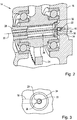
- For a complete understanding of the objects, techniques, and structure of the invention reference should be made to the following detailed description and accompanying drawings, wherein similar components are designated by identical reference numerals:
- Fig. 1
- is a side view of a vehicle using a gearbox comprising a lubrication device according to the present invention,
- Fig. 2
- is a partial cross sectional perspective view of the gearbox as used in the vehicle of
Fig. 1 , and - Fig. 3
- is an expanded back view through a plug utilized to enhance lubrication of a splined connection in the gearbox of
Fig. 2 . - Referring now to the drawings, and more particularly to
Fig. 1 , there is shown avehicle 10 having apower generating device 12 formed by a diesel engine that provides mechanical rotary motion to a power transfer device orgearbox 14 having rotating gears therein for the purpose of converting rotational speed and torque into another speed and torque.Vehicle 10 is shown as an agricultural vehicle, although it is recognized that the invention may be also incorporated into any other vehicle, such as a construction, forestry, industrial, and mining vehicle. - Referring to
Figs. 2 and 3 , thegearbox 14 includesgearbox housing 16, having alubrication passage 18 therein.Lubrication passage 18 is in fluid communication withlubrication cavity 20 andspray nozzle 22. Lubrication fluid (i.e., lubrication oil) passing through thelubrication passage 18 then flows first throughspray nozzle 22 and then throughlubrication cavity 20 as it is directed towards a rotating component orgear 24, and, more specifically, tointernal splines 26 along an axially extending opening of thegear 24.Spray nozzle 22 may be a machined opening tolubrication passage 18.Lubrication cavity 20 serves to protectspray nozzle 22 and to focus the lubrication fluid emanating fromspray nozzle 22. Further,lubrication cavity 20 allows the stream of lubrication fluid to be somewhat shielded from the movement of air currents withingearbox housing 16. - The
internal splines 26 forming a splined connection together with asplined shaft 28 having a pattern of external splines thereon which corresponds to theinternal splines 26. - An
axis 30 defines the rotational axis of thegear 24, which corresponds to the rotational axis ofsplined shaft 28.Axis 30 also generally corresponds to the orientation of lubrication fluid coming fromspray nozzle 22 andlubrication cavity 20 as it is directed toward the splined connection, and more precisely, to the interaction of the external splines of thesplined shaft 28 with theinternal splines 26 of thegear 24. At one end of theinternal splines 26, there is acounterbore 32, which is sized so thatplug 34 may frictionally engagecounterbore 32 to be retained therein.Plug 34 is symmetrical, having a cup-like shape with ahole 36 centrally located therein.Hole 36 located inplug 34 is positioned such that lubrication fluid emanating fromspay nozzle 22 andlubrication cavity 20 is directed generally throughhole 36 so that lubrication fluid is supplied to the splined connection. -
Splined shaft 28 can slide in the direction ofaxis 30 whilegear 24 andsplined shaft 28 are rotating, wherein the lubrication fluid contained therein helps prevent any fretting of the splined connection. There is a distance betweenhole 36 andlubrication cavity 20 so that, if lubrication fluid is to substantially fill the open cavity defined byplug 34,internal splines 26 and splinedshaft 28, lubrication fluid can exit back throughhole 36. Also, in the event that splinedshaft 28 slides towardsplug 34, lubrication fluid may be forced back throughhole 36. The positioning ofplug 34 incounterbore 32 thereby provides a lubrication dam in which lubrication fluid entering throughhole 36 will, by centrifugal force, be thrown againstinternal splines 26 with the lubrication fluid moving generally betweensplined shaft 28 andinternal splines 26 to keep the splined connection well-lubricated. - Referring now to
Fig. 3 , an expanded back view throughplug 34 is shown.Spray nozzle 22 is substantially concentrically located relative to bothlubrication cavity 20 andhole 36 ofplug 34.Lubrication passage 18 is shown in fluid communication withspray nozzle 22 andlubrication cavity 20. Even though there is a space betweengearbox housing 16 andgear 24, and hence also withlubrication cavity 20,internal splines 26 receive lubrication fluid that passes throughlubrication passage 18, so even theinternal splines 26 can be considered as being in fluid communication withlubrication passage 18. - Counterbore 32 is machined into back of
gear 24, whereinplug 34 can be considered to be a soft plug withhole 36 therein. Lubrication fluid is sprayed throughhole 36 passes then throughplug 34 in the area of the splined connection. Plug 34 traps the lubrication fluid and forces it to go through the splines by way of centrifugal head pressure created by the rotation of the parts. This advantageously eliminates, or at least minimizes, spline fretting of the splined connection when the splines are spinning at a high speed. Additionally, it eliminates the need for complex machining and/or seals on or around the outside of the area of the splined connection to force lubrication fluid into the splines.
Claims (8)
- A lubrication device for lubricating a splined connection, the device comprising at least one rotating component (24) having internal splines (26) along an axially extending opening; and a splined shaft (28) having a pattern of external splines thereon which corresponds to said internal splines (26), characterized in that a plug (34) is positioned in said axially extending opening, said plug (34) having a hole (36) centrally located therein.
- The lubrication device according to claim 1, characterized in that said splined shaft (28) and said plug (34) are located on opposite ends of the axially extending opening.
- The lubrication device according to claim 1 or 2, characterized in that said splined shaft (28) is driven by said rotating component (24).
- The lubrication device according to one of claims 1 to 3, characterized by a lubrication spray nozzle (22) directing lubrication fluid through said hole (36).
- The lubrication device according to one of claims 1 to 4, characterized in that said plug (34) is symmetrical, having a cup-like shape.
- The lubrication device according to one of claims 1 to 5, characterized in that said axially extending opening has a counterbore (32) which is sized so that said plug (34) is frictionally engaged.
- The lubrication device according to one of claims 1 to 6, characterized in that a lubrication passage (18) is directed toward said hole (36) being substantially aligned with said axially extending opening.
- A vehicle, comprising a power generating device (12); and a power transfer device (14) coupled to said power generating device (12), characterized by a lubrication device according to one of claims 1 to 7.
Applications Claiming Priority (1)
| Application Number | Priority Date | Filing Date | Title |
|---|---|---|---|
| US13/052,364 US20120240708A1 (en) | 2011-03-21 | 2011-03-21 | Power Transfer Box Spline Lubrication Device |
Publications (1)
| Publication Number | Publication Date |
|---|---|
| EP2503193A1 true EP2503193A1 (en) | 2012-09-26 |
Family
ID=45874662
Family Applications (1)
| Application Number | Title | Priority Date | Filing Date |
|---|---|---|---|
| EP12159154A Withdrawn EP2503193A1 (en) | 2011-03-21 | 2012-03-13 | Lubrication device for lubricating a splined connection |
Country Status (5)
| Country | Link |
|---|---|
| US (1) | US20120240708A1 (en) |
| EP (1) | EP2503193A1 (en) |
| CN (1) | CN102691780A (en) |
| AU (1) | AU2012201648A1 (en) |
| RU (1) | RU2012108749A (en) |
Families Citing this family (3)
| Publication number | Priority date | Publication date | Assignee | Title |
|---|---|---|---|---|
| DE102012214771B4 (en) * | 2012-08-20 | 2019-11-21 | Schaeffler Technologies AG & Co. KG | Plug-in shaft system and differential with plug-in shaft system |
| CN110644425B (en) * | 2019-09-11 | 2021-06-15 | 广东省水利水电建设有限公司 | Ecological retaining dam and construction method thereof |
| CN111472980A (en) * | 2019-12-21 | 2020-07-31 | 合肥皖化电机技术开发有限责任公司 | Furnace water pump speed increasing method |
Citations (9)
| Publication number | Priority date | Publication date | Assignee | Title |
|---|---|---|---|---|
| US2116166A (en) * | 1937-07-01 | 1938-05-03 | Joseph D Christian | Speed change device |
| US2670697A (en) * | 1945-08-22 | 1954-03-02 | Edgar N Meakin | Pellet mill |
| US3380555A (en) * | 1965-08-18 | 1968-04-30 | Caterpillar Tractor Co | System for lubrication of rotating elements |
| CA978869A (en) * | 1972-04-14 | 1975-12-02 | Lawrence R. Cline | Oil retaining reservoir for a gear drive mechanism |
| US4341296A (en) * | 1980-09-22 | 1982-07-27 | United Technologies Corporation | Flow divider for liquid coolant or lubricant |
| EP0148331A2 (en) * | 1983-10-14 | 1985-07-17 | Nissan Motor Co., Ltd. | Output gear of automatic transmission |
| US5033585A (en) * | 1989-07-12 | 1991-07-23 | Societe Anonyme Dite Hispano Suiza | Device for controlling lubricant flow |
| US5366399A (en) * | 1993-12-13 | 1994-11-22 | Brunswick Corporation | Marine stern drive with lubricated and semi-sealed engine output coupler |
| US20080014805A1 (en) * | 2006-05-25 | 2008-01-17 | Honda Motor Co., Ltd. | Outboard engine system |
Family Cites Families (13)
| Publication number | Priority date | Publication date | Assignee | Title |
|---|---|---|---|---|
| US1511940A (en) * | 1923-09-22 | 1924-10-14 | Boyer F Walter | Nonclogging spray nozzle |
| US1730099A (en) * | 1926-03-23 | 1929-10-01 | Tribbett George | Carburetor spray nozzle |
| US2125445A (en) * | 1937-02-05 | 1938-08-02 | Worthington Pump & Mach Corp | Spray nozzle |
| US2105154A (en) * | 1937-06-07 | 1938-01-11 | Norman G Maxon | Spray nozzle |
| US2319767A (en) * | 1941-08-28 | 1943-05-18 | Monarch Mfg Works Inc | Spray nozzle |
| US2550573A (en) * | 1946-10-05 | 1951-04-24 | Buensod Stacey Inc | Whirler spray nozzle with overhanging lip |
| US3785458A (en) * | 1972-04-14 | 1974-01-15 | Caterpillar Tractor Co | Lubrication system for a gear drive mechanism |
| US5005437A (en) * | 1987-07-07 | 1991-04-09 | Zahnradfabrik Friedrichshafen Ag | Device for cleaning lubricating oil in a gearbox |
| US4844202A (en) * | 1987-09-28 | 1989-07-04 | Sundstrand Corporation | Lubrication system for and method of minimizing heat rejection in gearboxes |
| US5119905A (en) * | 1991-10-28 | 1992-06-09 | General Motors Corporation | Accessory drive spline lubrication system for a turbine engine reduction gear box |
| US8312858B2 (en) * | 2006-12-22 | 2012-11-20 | Kohler Co. | System and method for lubricating power transmitting elements |
| FR2921455B1 (en) * | 2007-09-25 | 2010-01-01 | Hispano Suiza Sa | GEAR SYSTEM WITH LUBRICATION. |
| US8794107B2 (en) * | 2010-05-05 | 2014-08-05 | Hamilton Sundstrand Corporation | Submerged gear and bearing guard |
-
2011
- 2011-03-21 US US13/052,364 patent/US20120240708A1/en not_active Abandoned
-
2012
- 2012-03-07 RU RU2012108749/11A patent/RU2012108749A/en not_active Application Discontinuation
- 2012-03-13 EP EP12159154A patent/EP2503193A1/en not_active Withdrawn
- 2012-03-16 CN CN2012100719222A patent/CN102691780A/en active Pending
- 2012-03-20 AU AU2012201648A patent/AU2012201648A1/en not_active Abandoned
Patent Citations (9)
| Publication number | Priority date | Publication date | Assignee | Title |
|---|---|---|---|---|
| US2116166A (en) * | 1937-07-01 | 1938-05-03 | Joseph D Christian | Speed change device |
| US2670697A (en) * | 1945-08-22 | 1954-03-02 | Edgar N Meakin | Pellet mill |
| US3380555A (en) * | 1965-08-18 | 1968-04-30 | Caterpillar Tractor Co | System for lubrication of rotating elements |
| CA978869A (en) * | 1972-04-14 | 1975-12-02 | Lawrence R. Cline | Oil retaining reservoir for a gear drive mechanism |
| US4341296A (en) * | 1980-09-22 | 1982-07-27 | United Technologies Corporation | Flow divider for liquid coolant or lubricant |
| EP0148331A2 (en) * | 1983-10-14 | 1985-07-17 | Nissan Motor Co., Ltd. | Output gear of automatic transmission |
| US5033585A (en) * | 1989-07-12 | 1991-07-23 | Societe Anonyme Dite Hispano Suiza | Device for controlling lubricant flow |
| US5366399A (en) * | 1993-12-13 | 1994-11-22 | Brunswick Corporation | Marine stern drive with lubricated and semi-sealed engine output coupler |
| US20080014805A1 (en) * | 2006-05-25 | 2008-01-17 | Honda Motor Co., Ltd. | Outboard engine system |
Also Published As
| Publication number | Publication date |
|---|---|
| US20120240708A1 (en) | 2012-09-27 |
| RU2012108749A (en) | 2013-09-20 |
| CN102691780A (en) | 2012-09-26 |
| AU2012201648A1 (en) | 2012-10-11 |
Similar Documents
| Publication | Publication Date | Title |
|---|---|---|
| US9933066B2 (en) | Vehicle drive transfer apparatus | |
| JP5064945B2 (en) | Power unit | |
| EP2503194B1 (en) | Lubrication device for directing lubrication fluid to a meshing area in a gearbox | |
| EP1813839A2 (en) | Positive lubrication of a meshing gear | |
| JP2016098986A (en) | Vehicle drive device | |
| JP2016001027A (en) | Transmission lubrication mechanism | |
| US20120024656A1 (en) | Flywheel having lubrication-flow passageway | |
| US20120240708A1 (en) | Power Transfer Box Spline Lubrication Device | |
| CN100408884C (en) | Gear lubricating device | |
| CN107110424B (en) | The lubricating oil of turbine equipment collects cap | |
| US7140995B2 (en) | Gear drive | |
| US20110180352A1 (en) | Machine having lubricant circuit | |
| DE102015211789A1 (en) | Gear arrangement with a lubricating oil-carrying hollow shaft | |
| CN215521914U (en) | A lubricating structure for gear box | |
| JPS59106761A (en) | Lubricant feeder of gear device | |
| KR20040033980A (en) | Lubricating structure of manual transmission | |
| JP2013015182A (en) | Lubrication structure of vehicle transmission | |
| JP2005239060A (en) | Gearbox for internal combustion engine | |
| JP5112372B2 (en) | Lubricating structure of driving force transmission device | |
| JP5329457B2 (en) | Shaft support structure of power transmission device | |
| CN205859054U (en) | Reductor | |
| CN222377148U (en) | Sun gear and gearbox assembly | |
| JP2006275192A (en) | Lubrication structure of oil pump drive mechanism | |
| KR100507150B1 (en) | Lubricating structure of manual transmission | |
| CN216643047U (en) | Active lubrication system of hybrid transmission assembly |
Legal Events
| Date | Code | Title | Description |
|---|---|---|---|
| PUAI | Public reference made under article 153(3) epc to a published international application that has entered the european phase |
Free format text: ORIGINAL CODE: 0009012 |
|
| AK | Designated contracting states |
Kind code of ref document: A1 Designated state(s): AL AT BE BG CH CY CZ DE DK EE ES FI FR GB GR HR HU IE IS IT LI LT LU LV MC MK MT NL NO PL PT RO RS SE SI SK SM TR |
|
| AX | Request for extension of the european patent |
Extension state: BA ME |
|
| STAA | Information on the status of an ep patent application or granted ep patent |
Free format text: STATUS: THE APPLICATION IS DEEMED TO BE WITHDRAWN |
|
| 18D | Application deemed to be withdrawn |
Effective date: 20130327 |