EP2503172A2 - Multi-disc frictional engagement mechanism - Google Patents
Multi-disc frictional engagement mechanism Download PDFInfo
- Publication number
- EP2503172A2 EP2503172A2 EP12001280A EP12001280A EP2503172A2 EP 2503172 A2 EP2503172 A2 EP 2503172A2 EP 12001280 A EP12001280 A EP 12001280A EP 12001280 A EP12001280 A EP 12001280A EP 2503172 A2 EP2503172 A2 EP 2503172A2
- Authority
- EP
- European Patent Office
- Prior art keywords
- piston
- receiving portion
- oil chamber
- hydraulic
- hydraulic pressure
- Prior art date
- Legal status (The legal status is an assumption and is not a legal conclusion. Google has not performed a legal analysis and makes no representation as to the accuracy of the status listed.)
- Withdrawn
Links
Images





Classifications
-
- F—MECHANICAL ENGINEERING; LIGHTING; HEATING; WEAPONS; BLASTING
- F16—ENGINEERING ELEMENTS AND UNITS; GENERAL MEASURES FOR PRODUCING AND MAINTAINING EFFECTIVE FUNCTIONING OF MACHINES OR INSTALLATIONS; THERMAL INSULATION IN GENERAL
- F16D—COUPLINGS FOR TRANSMITTING ROTATION; CLUTCHES; BRAKES
- F16D13/00—Friction clutches
- F16D13/58—Details
- F16D13/60—Clutching elements
-
- F—MECHANICAL ENGINEERING; LIGHTING; HEATING; WEAPONS; BLASTING
- F16—ENGINEERING ELEMENTS AND UNITS; GENERAL MEASURES FOR PRODUCING AND MAINTAINING EFFECTIVE FUNCTIONING OF MACHINES OR INSTALLATIONS; THERMAL INSULATION IN GENERAL
- F16D—COUPLINGS FOR TRANSMITTING ROTATION; CLUTCHES; BRAKES
- F16D13/00—Friction clutches
- F16D13/58—Details
- F16D13/60—Clutching elements
- F16D13/64—Clutch-plates; Clutch-lamellae
-
- F—MECHANICAL ENGINEERING; LIGHTING; HEATING; WEAPONS; BLASTING
- F16—ENGINEERING ELEMENTS AND UNITS; GENERAL MEASURES FOR PRODUCING AND MAINTAINING EFFECTIVE FUNCTIONING OF MACHINES OR INSTALLATIONS; THERMAL INSULATION IN GENERAL
- F16D—COUPLINGS FOR TRANSMITTING ROTATION; CLUTCHES; BRAKES
- F16D25/00—Fluid-actuated clutches
- F16D25/06—Fluid-actuated clutches in which the fluid actuates a piston incorporated in, i.e. rotating with the clutch
- F16D25/062—Fluid-actuated clutches in which the fluid actuates a piston incorporated in, i.e. rotating with the clutch the clutch having friction surfaces
- F16D25/063—Fluid-actuated clutches in which the fluid actuates a piston incorporated in, i.e. rotating with the clutch the clutch having friction surfaces with clutch members exclusively moving axially
- F16D25/0635—Fluid-actuated clutches in which the fluid actuates a piston incorporated in, i.e. rotating with the clutch the clutch having friction surfaces with clutch members exclusively moving axially with flat friction surfaces, e.g. discs
- F16D25/0638—Fluid-actuated clutches in which the fluid actuates a piston incorporated in, i.e. rotating with the clutch the clutch having friction surfaces with clutch members exclusively moving axially with flat friction surfaces, e.g. discs with more than two discs, e.g. multiple lamellae
-
- F—MECHANICAL ENGINEERING; LIGHTING; HEATING; WEAPONS; BLASTING
- F16—ENGINEERING ELEMENTS AND UNITS; GENERAL MEASURES FOR PRODUCING AND MAINTAINING EFFECTIVE FUNCTIONING OF MACHINES OR INSTALLATIONS; THERMAL INSULATION IN GENERAL
- F16D—COUPLINGS FOR TRANSMITTING ROTATION; CLUTCHES; BRAKES
- F16D25/00—Fluid-actuated clutches
- F16D25/12—Details not specific to one of the before-mentioned types
- F16D25/14—Fluid pressure control
-
- F—MECHANICAL ENGINEERING; LIGHTING; HEATING; WEAPONS; BLASTING
- F16—ENGINEERING ELEMENTS AND UNITS; GENERAL MEASURES FOR PRODUCING AND MAINTAINING EFFECTIVE FUNCTIONING OF MACHINES OR INSTALLATIONS; THERMAL INSULATION IN GENERAL
- F16D—COUPLINGS FOR TRANSMITTING ROTATION; CLUTCHES; BRAKES
- F16D48/00—External control of clutches
- F16D48/02—Control by fluid pressure
- F16D2048/0212—Details of pistons for primary or secondary cylinders especially adapted for fluid control
Definitions
- the present invention relates to a multi-disc frictional engagement mechanism used in a clutch/brake of an automatic transmission.
- a multi-disc frictional engagement mechanism is used to couple two members (both are rotational elements in the case of the clutch, one is a rotational element and the other is a non-rotational element in the case of the brake) which are coaxially arranged.
- a plurality of friction plates are mounted slidably in an axial direction on the respective two members and the friction plates of the two members are alternately arranged.
- the friction plates of the two members are pressed against each other by a hydraulic piston, the two members are coupled via the friction plates.
- a seal ring for producing a pressing force to a facing member by being deformed in axial and radial directions in response to the hydraulic pressure is constantly pressing the facing member, whereby fuel economy is worsened also by a sliding friction force of the seal ring.
- JP7-12221A discloses an improvement in fuel economy of a vehicle by ensuring a clearance between friction plates utilizing a biasing force of a spring in an uncoupled state and, thereby, reducing friction between the friction plates in the uncoupled state.
- JP7-12221A discloses an improvement in fuel economy of a vehicle by ensuring a clearance between friction plates utilizing a biasing force of a spring in an uncoupled state and, thereby, reducing friction between the friction plates in the uncoupled state.
- JP7-12221A discloses an improvement in fuel economy of a vehicle by ensuring a clearance between friction plates utilizing a biasing force of a spring in an uncoupled state and, thereby, reducing friction between the friction plates in the uncoupled state.
- the present invention aims to improve fuel economy of a vehicle including an automatic transmission by reducing a hydraulic pressure supplied to an oil chamber for displacing a hydraulic piston in a coupled state and a released state.
- a multi-disc frictional engagement mechanism for coupling a first member and a second member which are coaxially arranged.
- the multi-disc frictional engagement mechanism includes a plurality of first friction plates mounted on the first member slidably in an axial direction; a plurality of second friction plates mounted on the second member slidably in the axial direction, the plurality of first friction plates and the plurality of second friction plates being alternately arranged; a hydraulic piston arranged displaceably in a direction perpendicular to the first and second friction plates and including a radially extending pressure receiving portion; a piston oil chamber which causes a hydraulic pressure to act on the pressure receiving portion; an elastic member which comes into contact with the pressure receiving portion from a side opposite to the piston oil chamber to bias the hydraulic piston toward the first and second friction plates; and a lock mechanism which restricts a movement of the hydraulic piston in a coupling direction toward the first and second friction plates in a state where the hydraulic pressure is supplied to the piston oil chamber, the elastic member is
- the hydraulic pressure needs not be supplied to the oil chamber, which displaces the hydraulic piston, in the coupled state and released state.
- the hydraulic pressure supplied to the oil chamber can be reduced and, also, deformation of a seal ring can be suppressed to reduce a pressing force and reduce a sliding friction force by reducing the hydraulic pressure. Therefore, fuel economy of a vehicle including an automatic transmission can be improved.
- FIG. 1 is a sectional view of a multi-disc clutch according to a first embodiment of the present invention.
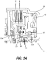
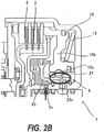
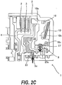
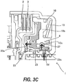
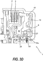
- FIGS. 2A to 2E are views showing a coupling operation of the multi-disc clutch.
- FIGS. 3A to 3D are views showing a releasing operation of the multi-disc clutch.
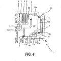
- FIG. 4 is a sectional view of a multi-disc clutch according to a second embodiment of the present invention.
- FIG. 5 is a view showing a releasing operation of the multi-disc clutch.
- FIG. 6 is a view showing a coupling operation of the multi-disc clutch.
- FIG. 1 is a sectional view of a multi-disc clutch 1 according to a first embodiment of the present invention.
- the multi-disc clutch 1 is a frictional engagement mechanism which is arranged in a transmission case of an automatic transmission and integrally rotatably couples a clutch hub 4 and a clutch drum 5, which are coaxially arranged, by coupling driven plates 2 and drive plates 3.
- the clutch hub 4 is a tubular member with an open right side in FIG. 1 and coupled to an unillustrated rotational element (shaft, gear or the like).
- the clutch drum 5 is a tubular member having an open left side in FIG. 1 and including a folded portion 5a inside.
- the clutch drum 5 is rotatably supported at the folded portion 5a via seal rings 11s provided on a drum support 6 fixed in the transmission.
- the clutch drum 5 is coupled to another unillustrated rotational element (shaft, gear or the like) and transmits rotation input from the other rotational element to the clutch hub 4 via the driven plates 2 and the drive plates 3.
- Spline grooves extending in an axial direction are formed on the outer periphery of the clutch hub 4, and a plurality of driven plates 2 are fitted slidably in the axial direction in the spline grooves.
- spline grooves extending in the axial direction are also formed on the inner periphery of the clutch drum 5, and a plurality of drive plates 3 are fitted slidably in the axial direction in the spline grooves.
- the driven plates 2 are metal discs and friction materials are bonded to both surfaces thereof.
- the drive plates 3 are metal discs.
- the driven plates 2 and the drive plates 3 are alternately arranged, i.e. arranged in a nested manner.
- a retaining plate 7 is further fitted in the spline grooves of the clutch drum 5. A displacement of the retaining plate 7 to the left of FIG. 1 is restricted by a snap ring 8.
- a hydraulic piston 10 is housed in the clutch drum 5.
- the driven plates 2 and the drive plates 3 are coupled and released by displacing the hydraulic piston 10 in a direction perpendicular to the driven plates 2 and the drive plates 3.
- a movement of the hydraulic piston 10 toward the driven plates 2 and the drive plates 3 is expressed by "to advance” and a movement thereof away from the driven plates 2 and the drive plates 3 is expressed by “to retract”.
- a direction toward the driven plates 2 and the drive plates 3 is expressed by a "coupling direction” and a direction away therefrom is expressed by a "releasing direction”.
- the hydraulic piston 10 includes a tubular piston portion 10a facing the driven plates 2 and the drive plates 3 and a pressure receiving portion 10b extending radially inward from the rear end of the piston portion 10a.
- the piston portion 10a can slide along the inner periphery of the clutch drum 5 in the coupling and releasing directions.
- an inner peripheral side of the pressure receiving portion 10b is tubular.
- Recessed portions 10e, 10f are respectively formed in the outer and inner peripheral end surfaces of the pressure receiving portion 10b, and D-rings 11d are respectively housed in the recessed portions 10e, 10f.
- a high-load diaphragm spring 13 is arranged between the pressure receiving portion 10b and the clutch drum 5.
- the spring 13 comes into contact with the pressure receiving portion 10b from a side opposite to a second oil chamber 22 to be described later via a retainer 14, thereby biasing the hydraulic piston 10 in the coupling direction.
- An opening side of the clutch drum 5 is sealed by an end plate 15 except at an outermost peripheral part where the piston portion 10a of the hydraulic piston 10 is arranged.
- the inner peripheral end of the end plate 15 is supported by the folded portion 5a of the clutch drum 5 and fixed to the clutch drum 5 by the snap ring 8 mounted on the folded portion 5a and a projecting portion 5b formed on the folded portion 5a.
- An oil seal 16 is mounted on the outer peripheral end of the end plate 15, and the outer peripheral end of the end plate 15 slides in contact with the inner periphery of the piston portion 10a via the oil seal 16.
- An oil chamber 20 is defined by the end plate 15, the hydraulic piston 10 and the clutch drum 5.
- the oil chamber 20 is partitioned into a first oil chamber 21 and the second oil chamber 22 by a ball retaining piston 23 arranged displaceably in the axial direction in the oil chamber 20.
- the ball retaining piston 23 includes a disc-shaped piston portion 23a and a tubular shaft portion 23b extending in the axial direction from the inner peripheral end of the piston portion 23a.
- An end part of the shaft portion 23b serves as a holding portion 23c raised radially outward (upward in FIG. 1 ).
- a recessed portion 23d is formed at the outer peripheral end of the piston portion 23a, and a D-ring 11d is mounted in the recessed portion 23d.
- the outer peripheral end of the piston portion 23a slides in contact with the end plate 15 via the D-ring 11d.
- a tubular sleeve 25 is interposed between the holding portion 23c and the end surface of the pressure receiving portion 10b of the hydraulic piston 10.
- the sleeve 25 is formed with a plurality of (eight to twelve) holes 26 in a circumferential direction, and lock balls 27 are respectively housed and held in the holes 26. Diameters of the plurality of holes 26 are respectively larger than the lock balls 27, which can freely move in the holes 26 unless coming into contact with the holding portion 23c of the ball retaining piston 23.
- the ball retaining piston 23, the sleeve 25. the lock balls 27 and a receiving portion 10c constitute a lock mechanism 9 for restricting a movement of the hydraulic piston 10 in the coupling direction.
- the clutch drum 5 is formed with a first oil path 5c for supplying and discharging the hydraulic pressure to and from the first oil chamber 21 and a second oil path 5d for supplying and discharging the hydraulic pressure to and from the second oil chamber 22.
- An apply pressure can be supplied to the first oil chamber 21 from an oil path 6a formed in the drum support 6 via the first oil path 5c.
- a release pressure can be supplied to the second oil chamber 22 from an oil path 6b formed in the drum support 6 via the second oil path 5d.
- the seal rings 11s are disposed at the opposite sides of the oil paths 5c, 5d, 6a and 6b lest the hydraulic pressure should leak from these oil paths 5c, 5d, 6a and 6b.
- the seal rings 11s are deformed in the axial and radial directions in response to the hydraulic pressure from the oil paths 5c, 5d, 6a and 6b, thereby producing a force for pressing the drum support 6 to seal between the clutch drum 5 and the drum support 6.
- a hydraulic pressure prepared by an unillustrated hydraulic control circuit using a hydraulic pressure discharged from an unillustrated oil pump as a source pressure is supplied to the first and second oil chambers 21, 22.
- a state shown in FIG. 1 is a lock state where the multi-disc clutch 1 is released and the lock mechanism 9 is operating. That is, the hydraulic piston 10 is located at a most retracted position and the spring 13 is compressed. The lock balls 27 are engaged with the receiving portion 10c at the end surface of the pressure receiving portion 10b, and the holding portion 23c of the ball retaining piston 23 is in contact with the lock balls 27, thereby preventing the lock balls 27 from coming out of the receiving portion 10c. This makes it impossible for the hydraulic piston 10 to advance from the most retracted position.
- FIGS. 2A to 2E show movements when the multi-disc clutch 1 changes from the released state to the coupled state.
- the apply pressure is first supplied from the first oil path 5c to the first oil chamber 21 ( FIG. 2A ).
- the hydraulic pressure of the first oil chamber 21 acts on the piston portion 23a of the ball retaining piston 23, the ball retaining piston 23 advances and the holding portion 23c of the ball retaining piston 23 is separated from the lock balls 27 ( FIG. 2B ).
- the hydraulic piston 10 is caused to advance by the biasing force of the spring 13, the driven plates 2 and the drive plates 3 are pressed against each other by the piston portion 10a to be coupled, i.e. the multi-disc clutch 1 is coupled, and the clutch hub 4 and the clutch drum 5 are coupled ( FIG. 2D ).
- FIGS. 3A to 3D show movements when the multi-disc clutch 1 changes from the coupled state to the released state.
- the release pressure is first supplied from the second oil path 5d to the second oil chamber 22 ( FIG. 3A ).
- the hydraulic piston 10 is retracted and the spring 13 is compressed.
- the hydraulic pressure is supplied to the second oil chamber 22 only temporarily during the releasing operation.
- the multi-disc clutch 1 according to this embodiment requires no supply of the hydraulic pressure not only to maintain the coupled state, but also to maintain the released state.
- the hydraulic pressure needs not be supplied to the oil chambers 21, 22 in the coupled state and the released state, and fuel economy of a vehicle including the automatic transmission can be improved by reducing the hydraulic pressure supplied to the oil chambers 21, 22.
- the lock mechanism 9 is a ball lock mechanism using the lock balls 27, sticking of the hydraulic piston 10 caused by an engaging member used for locking being got stuck with peripheral members can be prevented.
- FIG. 4 is a sectional view of a multi-disc clutch 1 according to the second embodiment of the present invention.
- the second embodiment is the same as the first embodiment in that a clutch hub 4 and a clutch drum 5 are integrally rotatably coupled via driven plates 2 and drive plates 3, a spring 13 for biasing a hydraulic piston 10 in an axial direction is provided and an oil chamber 20 is defined by the hydraulic piston 10, the clutch drum 5 and an end plate 15.
- Constructions common to the first embodiment are denoted by the same reference numerals. The following description is centered on points of difference.
- a tension plate 28 is interposed between the hydraulic piston 10 and the driven plates 2, the drive plates 3.
- a lock mechanism 9 is arranged at an inner peripheral side of the clutch drum 5. Unlike the lock mechanism 9 of the first embodiment, the lock mechanism 9 includes a tubular base member 31 to be fitted on a folded portion 5a and a lock piston 32 and a lock spring 33 housed in a recessed portion 31a formed on the outer periphery of the base member 31. The lock spring 33 biases the lock piston 32 toward the oil chamber 20.
- a receiving portion 10c of the hydraulic piston 10 is shaped to correspond to the lock piston 32 and formed such that about a half of the upper surface of the lock piston 32 is exposed to the oil chamber 20 with the lock piston 32 fitted.
- An oil path 5e is formed in the folded portion 5a of the clutch drum 5, so that the supply and discharge of a hydraulic pressure to and from the oil chamber 20 can be made through an oil path 6c formed in a drum support 6 via the oil path 5e.
- a diameter of the oil path 5e is sufficiently smaller than that of the oil path 6c and the oil path 5e functions as a throttle in the case of supplying and discharging the hydraulic pressure to and from the oil chamber 20.
- a state shown in FIG. 4 is a released state of the multi-disc clutch 1 and a lock state where a movement of the hydraulic piston 10 in a coupling direction is restricted by the lock mechanism 9.
- the leading end of the hydraulic piston 10 is separated from the driven plates 2 and the drive plates 3, a biasing force of the spring 13 does not act on the driven plates 2 and the drive plates 3 and the multi-disc clutch 1 is in the released state.
- the hydraulic piston 10 is located at a most retracted position, the spring 13 is compressed, the lock piston 32 is engaged with the receiving portion 10c at an end part of a pressure receiving portion 10b, and the hydraulic piston 10 cannot advance from the most retracted position. In this state, even if the supply of the hydraulic pressure to the oil chamber 20 is stopped, the multi-disc clutch 1 is maintained in the released state.
- FIG. 5 shows movements when the multi-disc clutch 1 changes from the coupled state to the released state.
- a high hydraulic pressure capable of retracting the hydraulic piston 10 is first supplied to the oil chamber 20 from the oil path 5e (X 1 in FIG. 5 ).
- the hydraulic piston 10 is retracted, the spring 13 is compressed and the lock piston 32 is retracted against a biasing force of the lock spring 33 (X 2 in FIG. 5 ).
- the lock piston 32 having a smaller volume change amount per stroke than the hydraulic piston 10 returns (projects) earlier than the hydraulic piston 10 is pushed back by the spring 13 and is engaged with the receiving portion 10c of the pressure receiving portion 10b (X 5 in FIG. 5 ).
- the lock mechanism 9 reaches the lock state, the movement of the hydraulic piston 10 in the coupling direction is restricted, and the released state of the multi-disc clutch 1 is maintained even if the hydraulic pressure of the oil chamber 20 becomes zero.
- the hydraulic pressure is supplied to the oil chamber 20 only temporarily during the releasing operation.
- FIG. 6 shows movements when the multi-disc clutch 1 changes from the released state to the coupled state.
- a hydraulic pressure of such a magnitude as to retract the lock piston 32 against the biasing force of the lock spring 33 is first supplied to the oil chamber 20 from the oil path 5e (Y 1 in FIG. 6 ).
- the lock piston 32 comes out of the receiving portion 10c of the pressure receiving portion 10b and the hydraulic piston 10 is made movable in the coupling direction (Y 2 in FIG. 6 ).
- the supply of the hydraulic pressure to the oil chamber 20 is stopped (Y 5 in FIG. 6 ). Thereafter, the hydraulic pressure in the oil chamber 20 is reduced by being discharged via the oil path 5e. However, even if the supply of the hydraulic pressure to the oil chamber 20 becomes zero, the biasing force of the spring 13 acts on the driven plates 2 and the drive plates 3 and the coupled state of the multi-disc clutch 1 is maintained. The hydraulic pressure is supplied to the oil chamber 20 only temporarily during the coupling operation.
- the hydraulic pressure needs not be supplied to the oil chamber 20 in the coupled state and the released state and the hydraulic pressure supplied to the oil chamber 20 can be reduced as in the first embodiment. Further, when the hydraulic pressure supplied to the oil chamber 20 decreases, a pressing force of seal rings 11s decreases to reduce a slide friction force between the seal rings 11s and the drum support 6. Therefore, fuel economy of a vehicle including an automatic transmission can be improved.
- the present invention is applied to the multi-disc clutch 1 in the above embodiments, but may also be applied to a brake in which one of elements to be coupled is a rotational element and the other element is a non-rotational element.
- the hydraulic pressure may only be reduced (hydraulic pressure after a reduction is equal to or more than zero).
Landscapes
- Engineering & Computer Science (AREA)
- General Engineering & Computer Science (AREA)
- Mechanical Engineering (AREA)
- Physics & Mathematics (AREA)
- Fluid Mechanics (AREA)
- Hydraulic Clutches, Magnetic Clutches, Fluid Clutches, And Fluid Joints (AREA)
Abstract
Description
- The present invention relates to a multi-disc frictional engagement mechanism used in a clutch/brake of an automatic transmission.
- In a clutch/brake of an automatic transmission, a multi-disc frictional engagement mechanism is used to couple two members (both are rotational elements in the case of the clutch, one is a rotational element and the other is a non-rotational element in the case of the brake) which are coaxially arranged.
- In the multi-disc frictional engagement mechanism, a plurality of friction plates are mounted slidably in an axial direction on the respective two members and the friction plates of the two members are alternately arranged. When the friction plates of the two members are pressed against each other by a hydraulic piston, the two members are coupled via the friction plates.
- In the multi-disc frictional engagement mechanism having the above construction, it is necessary to drive an oil pump and constantly supply a hydraulic pressure to an oil chamber for displacing the hydraulic piston to maintain a coupled state, which has caused a problem of worsening fuel economy of a vehicle including an automatic transmission.
- Further, in the case of constantly supplying the hydraulic pressure, a seal ring for producing a pressing force to a facing member by being deformed in axial and radial directions in response to the hydraulic pressure is constantly pressing the facing member, whereby fuel economy is worsened also by a sliding friction force of the seal ring.
-
JP7-12221A - The present invention aims to improve fuel economy of a vehicle including an automatic transmission by reducing a hydraulic pressure supplied to an oil chamber for displacing a hydraulic piston in a coupled state and a released state.
- According to an aspect of the present invention, a multi-disc frictional engagement mechanism for coupling a first member and a second member which are coaxially arranged is provided. The multi-disc frictional engagement mechanism includes a plurality of first friction plates mounted on the first member slidably in an axial direction; a plurality of second friction plates mounted on the second member slidably in the axial direction, the plurality of first friction plates and the plurality of second friction plates being alternately arranged; a hydraulic piston arranged displaceably in a direction perpendicular to the first and second friction plates and including a radially extending pressure receiving portion; a piston oil chamber which causes a hydraulic pressure to act on the pressure receiving portion; an elastic member which comes into contact with the pressure receiving portion from a side opposite to the piston oil chamber to bias the hydraulic piston toward the first and second friction plates; and a lock mechanism which restricts a movement of the hydraulic piston in a coupling direction toward the first and second friction plates in a state where the hydraulic pressure is supplied to the piston oil chamber, the elastic member is compressed by the pressure receiving portion and the first and second friction plates are not coupled.
- According to the above aspect, the hydraulic pressure needs not be supplied to the oil chamber, which displaces the hydraulic piston, in the coupled state and released state. Thus, the hydraulic pressure supplied to the oil chamber can be reduced and, also, deformation of a seal ring can be suppressed to reduce a pressing force and reduce a sliding friction force by reducing the hydraulic pressure. Therefore, fuel economy of a vehicle including an automatic transmission can be improved.
- Embodiments and advantages of this invention will be described in detail below with reference to the attached figures.
-
FIG. 1 is a sectional view of a multi-disc clutch according to a first embodiment of the present invention. -
FIGS. 2A to 2E are views showing a coupling operation of the multi-disc clutch. -
FIGS. 3A to 3D are views showing a releasing operation of the multi-disc clutch. -
FIG. 4 is a sectional view of a multi-disc clutch according to a second embodiment of the present invention. -
FIG. 5 is a view showing a releasing operation of the multi-disc clutch. -
FIG. 6 is a view showing a coupling operation of the multi-disc clutch. -
FIG. 1 is a sectional view of amulti-disc clutch 1 according to a first embodiment of the present invention. Themulti-disc clutch 1 is a frictional engagement mechanism which is arranged in a transmission case of an automatic transmission and integrally rotatably couples aclutch hub 4 and aclutch drum 5, which are coaxially arranged, by coupling drivenplates 2 anddrive plates 3. - The
clutch hub 4 is a tubular member with an open right side inFIG. 1 and coupled to an unillustrated rotational element (shaft, gear or the like). - The
clutch drum 5 is a tubular member having an open left side inFIG. 1 and including a foldedportion 5a inside. Theclutch drum 5 is rotatably supported at the foldedportion 5a viaseal rings 11s provided on adrum support 6 fixed in the transmission. Theclutch drum 5 is coupled to another unillustrated rotational element (shaft, gear or the like) and transmits rotation input from the other rotational element to theclutch hub 4 via the drivenplates 2 and thedrive plates 3. - Spline grooves extending in an axial direction are formed on the outer periphery of the
clutch hub 4, and a plurality of drivenplates 2 are fitted slidably in the axial direction in the spline grooves. Similarly, spline grooves extending in the axial direction are also formed on the inner periphery of theclutch drum 5, and a plurality ofdrive plates 3 are fitted slidably in the axial direction in the spline grooves. - The driven
plates 2 are metal discs and friction materials are bonded to both surfaces thereof. Thedrive plates 3 are metal discs. The drivenplates 2 and thedrive plates 3 are alternately arranged, i.e. arranged in a nested manner. - A
retaining plate 7 is further fitted in the spline grooves of theclutch drum 5. A displacement of theretaining plate 7 to the left ofFIG. 1 is restricted by asnap ring 8. - A
hydraulic piston 10 is housed in theclutch drum 5. The drivenplates 2 and thedrive plates 3 are coupled and released by displacing thehydraulic piston 10 in a direction perpendicular to the drivenplates 2 and thedrive plates 3. Note that, in the following description, a movement of thehydraulic piston 10 toward the drivenplates 2 and thedrive plates 3 is expressed by "to advance" and a movement thereof away from the drivenplates 2 and thedrive plates 3 is expressed by "to retract". Further, a direction toward the drivenplates 2 and thedrive plates 3 is expressed by a "coupling direction" and a direction away therefrom is expressed by a "releasing direction". - The
hydraulic piston 10 includes atubular piston portion 10a facing the drivenplates 2 and thedrive plates 3 and apressure receiving portion 10b extending radially inward from the rear end of thepiston portion 10a. Thepiston portion 10a can slide along the inner periphery of theclutch drum 5 in the coupling and releasing directions. - Further, an inner peripheral side of the
pressure receiving portion 10b is tubular. Recessedportions pressure receiving portion 10b, and D-rings 11d are respectively housed in the recessedportions - A high-
load diaphragm spring 13 is arranged between thepressure receiving portion 10b and theclutch drum 5. Thespring 13 comes into contact with thepressure receiving portion 10b from a side opposite to asecond oil chamber 22 to be described later via aretainer 14, thereby biasing thehydraulic piston 10 in the coupling direction. - An opening side of the
clutch drum 5 is sealed by anend plate 15 except at an outermost peripheral part where thepiston portion 10a of thehydraulic piston 10 is arranged. The inner peripheral end of theend plate 15 is supported by the foldedportion 5a of theclutch drum 5 and fixed to theclutch drum 5 by thesnap ring 8 mounted on the foldedportion 5a and a projectingportion 5b formed on the foldedportion 5a. Anoil seal 16 is mounted on the outer peripheral end of theend plate 15, and the outer peripheral end of theend plate 15 slides in contact with the inner periphery of thepiston portion 10a via theoil seal 16. - An
oil chamber 20 is defined by theend plate 15, thehydraulic piston 10 and theclutch drum 5. Theoil chamber 20 is partitioned into afirst oil chamber 21 and thesecond oil chamber 22 by aball retaining piston 23 arranged displaceably in the axial direction in theoil chamber 20. - The
ball retaining piston 23 includes a disc-shaped piston portion 23a and atubular shaft portion 23b extending in the axial direction from the inner peripheral end of thepiston portion 23a. An end part of theshaft portion 23b serves as aholding portion 23c raised radially outward (upward inFIG. 1 ). Arecessed portion 23d is formed at the outer peripheral end of thepiston portion 23a, and a D-ring 11d is mounted in the recessedportion 23d. The outer peripheral end of thepiston portion 23a slides in contact with theend plate 15 via the D-ring 11d. Note that, in the following description, a movement of theball retaining piston 23 to the right ofFIG. 1 is expressed by "to advance" and a movement thereof to the left ofFIG. 1 is expressed by "to retract". - A
tubular sleeve 25 is interposed between theholding portion 23c and the end surface of thepressure receiving portion 10b of thehydraulic piston 10. Thesleeve 25 is formed with a plurality of (eight to twelve)holes 26 in a circumferential direction, andlock balls 27 are respectively housed and held in theholes 26. Diameters of the plurality ofholes 26 are respectively larger than thelock balls 27, which can freely move in theholes 26 unless coming into contact with theholding portion 23c of theball retaining piston 23. - In this embodiment, the
ball retaining piston 23, thesleeve 25. thelock balls 27 and a receivingportion 10c constitute alock mechanism 9 for restricting a movement of thehydraulic piston 10 in the coupling direction. - The
clutch drum 5 is formed with afirst oil path 5c for supplying and discharging the hydraulic pressure to and from thefirst oil chamber 21 and asecond oil path 5d for supplying and discharging the hydraulic pressure to and from thesecond oil chamber 22. An apply pressure can be supplied to thefirst oil chamber 21 from anoil path 6a formed in thedrum support 6 via thefirst oil path 5c. Further, a release pressure can be supplied to thesecond oil chamber 22 from anoil path 6b formed in thedrum support 6 via thesecond oil path 5d. Since theoil paths clutch drum 5 and thedrum support 6 rotating relative to each other, the seal rings 11s are disposed at the opposite sides of theoil paths oil paths - The seal rings 11s are deformed in the axial and radial directions in response to the hydraulic pressure from the
oil paths drum support 6 to seal between theclutch drum 5 and thedrum support 6. - A hydraulic pressure prepared by an unillustrated hydraulic control circuit using a hydraulic pressure discharged from an unillustrated oil pump as a source pressure is supplied to the first and
second oil chambers - A state shown in
FIG. 1 is a lock state where themulti-disc clutch 1 is released and thelock mechanism 9 is operating. That is, thehydraulic piston 10 is located at a most retracted position and thespring 13 is compressed. Thelock balls 27 are engaged with the receivingportion 10c at the end surface of thepressure receiving portion 10b, and the holdingportion 23c of theball retaining piston 23 is in contact with thelock balls 27, thereby preventing thelock balls 27 from coming out of the receivingportion 10c. This makes it impossible for thehydraulic piston 10 to advance from the most retracted position. - In this state, the leading end of the
hydraulic piston 10 is separated from the drivenplates 2 and thedrive plates 3, a biasing force of thespring 13 does not act on the drivenplates 2 and thedrive plates 3 and themulti-disc clutch 1 is in the released state. Further, even if the supply of the hydraulic pressure to thesecond oil chamber 22 is stopped, themulti-disc clutch 1 is maintained in the released state. - Next, the coupling and releasing operations of the above
multi-disc clutch 1 are described. -
FIGS. 2A to 2E show movements when the multi-disc clutch 1 changes from the released state to the coupled state. - To couple the
multi-disc clutch 1, the apply pressure is first supplied from thefirst oil path 5c to the first oil chamber 21 (FIG. 2A ). By this, the hydraulic pressure of thefirst oil chamber 21 acts on thepiston portion 23a of theball retaining piston 23, theball retaining piston 23 advances and the holdingportion 23c of theball retaining piston 23 is separated from the lock balls 27 (FIG. 2B ). - When the holding
portion 23c is separated from thelock balls 27, thelock balls 27 are pushed out of the receivingportion 10c at the end surface of thepressure receiving portion 10b by the biasing force of thespring 13 transmitted via thepressure receiving portion 10b of thehydraulic piston 10, whereby the lock state by thelock mechanism 9 is removed (FIG. 2C ). - By this, the
hydraulic piston 10 is caused to advance by the biasing force of thespring 13, the drivenplates 2 and thedrive plates 3 are pressed against each other by thepiston portion 10a to be coupled, i.e. themulti-disc clutch 1 is coupled, and theclutch hub 4 and theclutch drum 5 are coupled (FIG. 2D ). - Thereafter, the supply of the apply pressure to the
first oil chamber 21 is stopped. When the supply of the apply pressure to thefirst oil chamber 21 is stopped, the hydraulic pressure is discharged from thefirst oil path 5c and the hydraulic pressure of thefirst oil chamber 21 is reduced and finally becomes zero (FIG. 2E ). - Even if the hydraulic pressure of the
first oil chamber 21 becomes zero, the biasing force of thespring 13 continues to act on the drivenplates 2 and thedrive plates 3 and themulti-disc clutch 1 is maintained in the coupled state. The hydraulic pressure is supplied to thefirst oil chamber 21 only during the coupling operation and no hydraulic pressure needs to be supplied to maintain the coupled state. -
FIGS. 3A to 3D show movements when the multi-disc clutch 1 changes from the coupled state to the released state. - To release the
multi-disc clutch 1, the release pressure is first supplied from thesecond oil path 5d to the second oil chamber 22 (FIG. 3A ). By this, thehydraulic piston 10 is retracted and thespring 13 is compressed. - When the
hydraulic piston 10 is retracted to the most retracted position, the axial-direction position of the receivingportion 10c at the end surface of thepressure receiving portion 10b and those of thelock balls 27 are aligned and a state is reached where thelock balls 27 are movable into the receivingportion 10c (FIG. 3B ). Note that, in this state, the biasing force of thespring 13 does not act on the drivenplates 2 and thedrive plates 3 and themulti-disc clutch 1 is released. - When the release pressure is further supplied to the
second oil chamber 22, the hydraulic pressure of thesecond oil chamber 22 acts on thepiston portion 23a of theball retaining piston 23, theball retaining piston 23 is retracted to the most retracted position and the holdingportion 23c of theball retaining piston 23 comes into contact with thelock balls 27. By this, thelock balls 27 enter the receivingportion 10c of thepressure receiving portion 10b and thelock mechanism 9 is locked (FIG. 3C ). - In the lock state, the supply of the release pressure to the
second oil chamber 22 is stopped (FIG. 3D ). Thereafter, the hydraulic pressure of thesecond oil chamber 22 is reduced by being discharged from thesecond oil path 5d and finally becomes zero. However, the movement of thehydraulic piston 10 in the coupling direction is kept restricted by thelock mechanism 9, the biasing force of thespring 13 does not act on the drivenplates 2 and thedrive plates 3, and themulti-disc clutch 1 is maintained in the released state. - The hydraulic pressure is supplied to the
second oil chamber 22 only temporarily during the releasing operation. Themulti-disc clutch 1 according to this embodiment requires no supply of the hydraulic pressure not only to maintain the coupled state, but also to maintain the released state. - Next, functions and effects of this embodiment are described.
- According to this embodiment, the hydraulic pressure needs not be supplied to the
oil chambers oil chambers - Further, when the hydraulic pressure supplied to the
oil chambers seal ring 11s and thedrum support 6. Thus, fuel economy can also be improved by this. - Further, since the
lock mechanism 9 is a ball lock mechanism using thelock balls 27, sticking of thehydraulic piston 10 caused by an engaging member used for locking being got stuck with peripheral members can be prevented. - Next, a second embodiment of the present invention is described.
-
FIG. 4 is a sectional view of amulti-disc clutch 1 according to the second embodiment of the present invention. - The second embodiment is the same as the first embodiment in that a
clutch hub 4 and aclutch drum 5 are integrally rotatably coupled via drivenplates 2 and driveplates 3, aspring 13 for biasing ahydraulic piston 10 in an axial direction is provided and anoil chamber 20 is defined by thehydraulic piston 10, theclutch drum 5 and anend plate 15. Constructions common to the first embodiment are denoted by the same reference numerals. The following description is centered on points of difference. - A
tension plate 28 is interposed between thehydraulic piston 10 and the drivenplates 2, thedrive plates 3. - A
lock mechanism 9 is arranged at an inner peripheral side of theclutch drum 5. Unlike thelock mechanism 9 of the first embodiment, thelock mechanism 9 includes atubular base member 31 to be fitted on a foldedportion 5a and alock piston 32 and alock spring 33 housed in a recessed portion 31a formed on the outer periphery of thebase member 31. Thelock spring 33 biases thelock piston 32 toward theoil chamber 20. - A receiving
portion 10c of thehydraulic piston 10 is shaped to correspond to thelock piston 32 and formed such that about a half of the upper surface of thelock piston 32 is exposed to theoil chamber 20 with thelock piston 32 fitted. - An
oil path 5e is formed in the foldedportion 5a of theclutch drum 5, so that the supply and discharge of a hydraulic pressure to and from theoil chamber 20 can be made through anoil path 6c formed in adrum support 6 via theoil path 5e. A diameter of theoil path 5e is sufficiently smaller than that of theoil path 6c and theoil path 5e functions as a throttle in the case of supplying and discharging the hydraulic pressure to and from theoil chamber 20. - A state shown in
FIG. 4 is a released state of themulti-disc clutch 1 and a lock state where a movement of thehydraulic piston 10 in a coupling direction is restricted by thelock mechanism 9. - That is, the leading end of the
hydraulic piston 10 is separated from the drivenplates 2 and thedrive plates 3, a biasing force of thespring 13 does not act on the drivenplates 2 and thedrive plates 3 and themulti-disc clutch 1 is in the released state. Thehydraulic piston 10 is located at a most retracted position, thespring 13 is compressed, thelock piston 32 is engaged with the receivingportion 10c at an end part of apressure receiving portion 10b, and thehydraulic piston 10 cannot advance from the most retracted position. In this state, even if the supply of the hydraulic pressure to theoil chamber 20 is stopped, themulti-disc clutch 1 is maintained in the released state. - Next, the coupling and releasing operations of the above
multi-disc clutch 1 are described. -
FIG. 5 shows movements when the multi-disc clutch 1 changes from the coupled state to the released state. - To release the
multi-disc clutch 1, a high hydraulic pressure capable of retracting thehydraulic piston 10 is first supplied to theoil chamber 20 from theoil path 5e (X1 inFIG. 5 ). By this, thehydraulic piston 10 is retracted, thespring 13 is compressed and thelock piston 32 is retracted against a biasing force of the lock spring 33 (X2 inFIG. 5 ). - When the
hydraulic piston 10 is retracted to the most retracted position, the biasing force of thespring 13 no longer acts on the drivenplates 2 and thedrive plates 3, whereby themulti-disc clutch 1 is released (X3 inFIG. 5 ). - When the
multi-disc clutch 1 is released, the supply of the hydraulic pressure to theoil chamber 20 is stopped (X4 inFIG. 5 ). Although the hydraulic pressure in theoil chamber 20 is discharged via theoil path 5e, the hydraulic pressure of theoil chamber 20 does not suddenly decrease since theoil path 5e functions as a throttle. - As a result, the
lock piston 32 having a smaller volume change amount per stroke than thehydraulic piston 10 returns (projects) earlier than thehydraulic piston 10 is pushed back by thespring 13 and is engaged with the receivingportion 10c of thepressure receiving portion 10b (X5 inFIG. 5 ). - By this, the
lock mechanism 9 reaches the lock state, the movement of thehydraulic piston 10 in the coupling direction is restricted, and the released state of themulti-disc clutch 1 is maintained even if the hydraulic pressure of theoil chamber 20 becomes zero. The hydraulic pressure is supplied to theoil chamber 20 only temporarily during the releasing operation. -
FIG. 6 shows movements when the multi-disc clutch 1 changes from the released state to the coupled state. - To couple the
multi-disc clutch 1, a hydraulic pressure of such a magnitude as to retract thelock piston 32 against the biasing force of thelock spring 33 is first supplied to theoil chamber 20 from theoil path 5e (Y1 inFIG. 6 ). By this, thelock piston 32 comes out of the receivingportion 10c of thepressure receiving portion 10b and thehydraulic piston 10 is made movable in the coupling direction (Y2 inFIG. 6 ). - When the
hydraulic piston 10 becomes movable in the coupling direction, thehydraulic piston 10 advances due to the biasing force of the spring 13 (Y3 inFIG. 6 ) and the drivenplates 2 and thedrive plates 3 are pressed to couple the multi-disc clutch 1 (Y4 inFIG. 6 ). - When the
multi-disc clutch 1 is coupled, the supply of the hydraulic pressure to theoil chamber 20 is stopped (Y5 inFIG. 6 ). Thereafter, the hydraulic pressure in theoil chamber 20 is reduced by being discharged via theoil path 5e. However, even if the supply of the hydraulic pressure to theoil chamber 20 becomes zero, the biasing force of thespring 13 acts on the drivenplates 2 and thedrive plates 3 and the coupled state of themulti-disc clutch 1 is maintained. The hydraulic pressure is supplied to theoil chamber 20 only temporarily during the coupling operation. - Also by the second embodiment, the hydraulic pressure needs not be supplied to the
oil chamber 20 in the coupled state and the released state and the hydraulic pressure supplied to theoil chamber 20 can be reduced as in the first embodiment. Further, when the hydraulic pressure supplied to theoil chamber 20 decreases, a pressing force ofseal rings 11s decreases to reduce a slide friction force between the seal rings 11s and thedrum support 6. Therefore, fuel economy of a vehicle including an automatic transmission can be improved. - Although the embodiments of the present invention have been described above, the above embodiments are only illustration of some application examples of the present invention and not of the nature to limit the technical scope of the present invention to the specific constructions of the above embodiments.
- For example, the present invention is applied to the
multi-disc clutch 1 in the above embodiments, but may also be applied to a brake in which one of elements to be coupled is a rotational element and the other element is a non-rotational element. - Although the supply of the hydraulic pressure is stopped to zero the hydraulic pressure in the coupled and released states in the above embodiments, the hydraulic pressure may only be reduced (hydraulic pressure after a reduction is equal to or more than zero).
- This application claims priority based on Japanese Patent Application No.
2011-62120
Claims (7)
- A multi-disc frictional engagement mechanism (1) for coupling a first member (4) and a second member (5) which are coaxially arranged, comprising;
a plurality of first friction plates (2) mounted on the first member (4) slidably in an axial direction;
a plurality of second friction plates (3) mounted on the second member (5) slidably in the axial direction, the plurality of first friction plates (2) and the plurality of second friction plates (3) being alternately arranged;
a hydraulic piston (10) arranged displaceably in a direction perpendicular to the first and second friction plates (2, 3) and including a radially extending pressure receiving portion (10b);
a piston oil chamber (20) which causes a hydraulic pressure to act on the pressure receiving portion (10b);
an elastic member (13) which comes into contact with the pressure receiving portion (11b) from a side opposite to the piston oil chamber (20) to bias the hydraulic piston (10) toward the first and second friction plates (2, 3); and
a lock mechanism (9) which restricts a movement of the hydraulic piston (10) in a coupling direction toward the first and second friction plates (2, 3) in a state where the hydraulic pressure is supplied to the piston oil chamber (20), the elastic member (13) is compressed by the pressure receiving portion (10b) and the first and second friction plates (2, 3) are not coupled. - The multi-disc frictional engagement mechanism (1) according to claim 1, wherein:the lock mechanism (9) includes an engaging member (27) movable toward the pressure receiving portion (10b), and a holding member (23) which comes into contact with the engaging member (27) moved toward the pressure receiving portion (10b) to hold the engaging member (27);the pressure receiving portion (10b) includes a receiving portion (10c), with which the engaging member (27) is to be engaged, at an end part; andthe engaging member (27) is moved by the hydraulic pressure supplied to the piston oil chamber (20) to be engaged with the receiving portion (10c) and come into contact with the holding member (23), whereby the movement of the hydraulic piston (10) in the coupling direction is restricted.
- The multi-disc frictional engagement mechanism (1) according to claim 2, wherein:the holding member (23) includes a piston portion (23a) which receives the hydraulic pressure of the piston oil chamber (20), and moves to a position where the holding member (23) is held in contact with the engaging member (27) by the hydraulic pressure supplied to the piston oil chamber (20).
- The multi-disc frictional engagement mechanism (1) according to claim 3, wherein:the restriction of the movement of the hydraulic piston (10) in the coupling direction by the lock mechanism (9) is removed by causing the hydraulic pressure to act on the piston portion (23a) from the side opposite to the piston oil chamber (20) and separating the holding member (23) from the engaging member (27).
- The multi-disc frictional engagement mechanism (1) according to any one of claims 2 to 4, further comprising:a tubular member (25) interposed between the pressure receiving portion (10c) and the holding member (23) and including a plurality of radially extending holes (26),wherein the engaging member (27) is a plurality of balls held in the plurality of holes (26).
- The multi-disc frictional engagement mechanism (1) according to claim 1, wherein:the lock mechanism (9) includes an engaging member (32) and a second elastic member (33) which biases the engaging member (32) toward the pressure receiving portion (10b);the pressure receiving portion (10b) includes a receiving portion (10c), with which the engaging member (32) is to be engaged, at an end part; andthe engaging member (32) is moved and engaged with the receiving portion (10c) by a biasing force of the second elastic member (33) earlier than the hydraulic piston (10) is pushed back by the elastic member (13), thereby restricting the movement of the hydraulic piston (10) in the coupling direction, when the hydraulic pressure supplied to the piston oil chamber (20) is reduced from a state where the hydraulic pressure is supplied to the piston oil chamber (20) and the elastic member (13) is compressed by the pressure receiving portion (10b).
- The multi-disc frictional engagement mechanism according to claim 6, wherein:the engaging member (32) is partially exposed to the piston oil chamber (20); andthe restriction of the movement of the hydraulic piston (10) in the coupling direction by the lock mechanism (9) is removed by temporarily supplying the hydraulic pressure to the piston oil chamber (20) and retracting the engaging member (32) against the biasing force of the second elastic member (33).
Applications Claiming Priority (1)
| Application Number | Priority Date | Filing Date | Title |
|---|---|---|---|
| JP2011062120A JP5669641B2 (en) | 2011-03-22 | 2011-03-22 | Multi-plate friction engagement mechanism |
Publications (2)
| Publication Number | Publication Date |
|---|---|
| EP2503172A2 true EP2503172A2 (en) | 2012-09-26 |
| EP2503172A3 EP2503172A3 (en) | 2013-09-04 |
Family
ID=45811244
Family Applications (1)
| Application Number | Title | Priority Date | Filing Date |
|---|---|---|---|
| EP12001280.2A Withdrawn EP2503172A3 (en) | 2011-03-22 | 2012-02-27 | Multi-disc frictional engagement mechanism |
Country Status (5)
| Country | Link |
|---|---|
| US (1) | US8875863B2 (en) |
| EP (1) | EP2503172A3 (en) |
| JP (1) | JP5669641B2 (en) |
| KR (1) | KR101288253B1 (en) |
| CN (1) | CN102691732B (en) |
Families Citing this family (19)
| Publication number | Priority date | Publication date | Assignee | Title |
|---|---|---|---|---|
| JP5650158B2 (en) * | 2012-05-31 | 2015-01-07 | ジヤトコ株式会社 | Friction engagement device |
| JP5782604B2 (en) | 2012-09-07 | 2015-09-24 | 株式会社豊田中央研究所 | Information processing apparatus and program |
| CN104704266B (en) * | 2012-09-26 | 2016-07-06 | 加特可株式会社 | automatic transmission and control method thereof |
| JP5844912B2 (en) * | 2012-09-26 | 2016-01-20 | ジヤトコ株式会社 | Automatic transmission having friction element with lock mechanism and control method thereof |
| WO2014050472A1 (en) * | 2012-09-26 | 2014-04-03 | ジヤトコ株式会社 | Automatic transmission equipped with friction element having locking mechanism attached thereto, and control method therefor |
| EP2908032A4 (en) * | 2012-09-26 | 2016-08-10 | Jatco Ltd | Automatic transmission equipped with friction element having locking mechanism attached thereto, and control method therefor |
| EP2902652A1 (en) * | 2012-09-26 | 2015-08-05 | Jatco Ltd | Automatic transmission and automatic-transmission control method |
| CN104662339A (en) * | 2012-09-26 | 2015-05-27 | 加特可株式会社 | Automatic transmission equipped with friction element having locking mechanism attached thereto, and control method therefor |
| WO2014050462A1 (en) * | 2012-09-26 | 2014-04-03 | ジヤトコ株式会社 | Clutch control device for automatic transmission |
| JP5887427B2 (en) * | 2012-12-21 | 2016-03-16 | ジヤトコ株式会社 | Automatic transmission clutch control device |
| DE102013008071A1 (en) | 2013-05-10 | 2014-11-13 | Borgwarner Inc. | Coupling device with lockable actuator |
| US10302150B2 (en) * | 2013-09-26 | 2019-05-28 | Aisin Aw Co., Ltd. | Clutch |
| CN104791395B (en) * | 2015-02-26 | 2018-09-07 | 长城汽车股份有限公司 | wet clutch and vehicle |
| WO2016193347A1 (en) * | 2015-06-03 | 2016-12-08 | Borgwarner Torqtransfer Systems Ab | Hydraulic coupling |
| JP6578231B2 (en) * | 2016-03-17 | 2019-09-18 | 本田技研工業株式会社 | Clutch device |
| DE102017004293A1 (en) * | 2017-05-04 | 2018-11-08 | Daimler Ag | coupling device |
| KR102261551B1 (en) * | 2017-06-14 | 2021-06-07 | 엘에스엠트론 주식회사 | Clutch apparatus |
| DE102017215582A1 (en) * | 2017-09-05 | 2019-03-07 | Zf Friedrichshafen Ag | Pneumatic actuator with wear compensation |
| CN114483813B (en) * | 2020-11-13 | 2025-06-24 | 克诺尔制动系统(大连)有限公司 | Self-adjusting mechanism for operating a clutch, clutch assembly, and vehicle |
Citations (3)
| Publication number | Priority date | Publication date | Assignee | Title |
|---|---|---|---|---|
| US3679033A (en) * | 1970-11-30 | 1972-07-25 | Gen Motors Corp | Propeller coupling |
| JPH0712221A (en) | 1993-06-29 | 1995-01-17 | Matsuda Sangyo Kk | Fastening force adjusting device for automatic transmission |
| JP2011062120A (en) | 2009-09-16 | 2011-03-31 | Kubota Corp | Common combine harvester |
Family Cites Families (13)
| Publication number | Priority date | Publication date | Assignee | Title |
|---|---|---|---|---|
| US3354994A (en) * | 1966-02-01 | 1967-11-28 | Caterpillar Tractor Co | Transmission locking means |
| DE2540191C3 (en) | 1975-09-10 | 1981-08-13 | Zahnradfabrik Friedrichshafen Ag, 7990 Friedrichshafen | Pressure fluid operated multi-plate clutch with upright ring cylinder |
| DE3118565C2 (en) | 1981-05-11 | 1984-11-29 | Zahnradfabrik Friedrichshafen Ag, 7990 Friedrichshafen | Multi-disc clutch |
| JPS5939326U (en) * | 1982-09-07 | 1984-03-13 | 三菱農機株式会社 | Hydraulic multi-disc clutch device |
| KR19980049475A (en) * | 1996-12-19 | 1998-09-15 | 박병재 | Clutch of automatic transmission |
| JP3877465B2 (en) | 1999-05-20 | 2007-02-07 | ナブテスコ株式会社 | Power transmission mechanism |
| GB0217309D0 (en) * | 2002-07-25 | 2002-09-04 | Lucas Industries Ltd | Drive disconnect device |
| FR2871109B1 (en) * | 2004-06-03 | 2006-09-22 | Peugeot Citroen Automobiles Sa | TRANSMISSION MODULE FOR A MOTORPOWER GROUP, IN PARTICULAR FOR MOTOR VEHICLES |
| DE102008027070A1 (en) * | 2007-06-20 | 2008-12-24 | Luk Lamellen Und Kupplungsbau Beteiligungs Kg | Locking mechanism for clutches and brakes |
| JP2009001165A (en) | 2007-06-21 | 2009-01-08 | Nissan Motor Co Ltd | Friction clutch |
| US8172058B2 (en) * | 2009-01-12 | 2012-05-08 | GM Global Technology Operations LLC | Latching clutch assembly and method of operating the same |
| KR101648984B1 (en) * | 2009-03-31 | 2016-08-17 | 쟈트코 가부시키가이샤 | Multi-plate frictional element |
| JP2010242852A (en) * | 2009-04-06 | 2010-10-28 | Honda Motor Co Ltd | Friction engagement device |
-
2011
- 2011-03-22 JP JP2011062120A patent/JP5669641B2/en not_active Expired - Fee Related
-
2012
- 2012-02-22 CN CN201210042046.0A patent/CN102691732B/en not_active Expired - Fee Related
- 2012-02-23 US US13/403,348 patent/US8875863B2/en not_active Expired - Fee Related
- 2012-02-27 EP EP12001280.2A patent/EP2503172A3/en not_active Withdrawn
- 2012-03-21 KR KR1020120028568A patent/KR101288253B1/en not_active Expired - Fee Related
Patent Citations (3)
| Publication number | Priority date | Publication date | Assignee | Title |
|---|---|---|---|---|
| US3679033A (en) * | 1970-11-30 | 1972-07-25 | Gen Motors Corp | Propeller coupling |
| JPH0712221A (en) | 1993-06-29 | 1995-01-17 | Matsuda Sangyo Kk | Fastening force adjusting device for automatic transmission |
| JP2011062120A (en) | 2009-09-16 | 2011-03-31 | Kubota Corp | Common combine harvester |
Also Published As
| Publication number | Publication date |
|---|---|
| KR101288253B1 (en) | 2013-07-26 |
| KR20120107868A (en) | 2012-10-04 |
| JP5669641B2 (en) | 2015-02-12 |
| CN102691732B (en) | 2014-11-19 |
| EP2503172A3 (en) | 2013-09-04 |
| CN102691732A (en) | 2012-09-26 |
| JP2012197851A (en) | 2012-10-18 |
| US8875863B2 (en) | 2014-11-04 |
| US20120241280A1 (en) | 2012-09-27 |
Similar Documents
| Publication | Publication Date | Title |
|---|---|---|
| US8875863B2 (en) | Multi-disc frictional engagement mechanism | |
| US8752686B2 (en) | Multi-disc frictional engagement mechanism | |
| CN104334904B (en) | Rub clamping close device | |
| US6315096B1 (en) | Friction engaging device | |
| EP3452735B1 (en) | Pneumatic clutch actuator | |
| US8151964B2 (en) | Multiple disc clutch apparatus | |
| US20130277164A1 (en) | Coupling and control assembly | |
| CN101548117B (en) | Friction engagement devices for automatic transmissions | |
| US6659251B2 (en) | Multiple plate clutch device | |
| US7845480B2 (en) | Frictional coupling device support structure and transmission | |
| EP3543554A1 (en) | Clutch apparatus | |
| WO2014050462A1 (en) | Clutch control device for automatic transmission | |
| CN108571536A (en) | Multi-disc wet clutch | |
| US11293499B2 (en) | Clutch device for transmission | |
| JP7416643B2 (en) | Multi-disc clutch device | |
| JP2008064241A (en) | Friction engagement device support structure and transmission | |
| CN114623170B (en) | Double-clutch linkage device and speed change mechanism | |
| JPH0979289A (en) | Friction engagement device | |
| JP2010203595A (en) | Piston | |
| WO2014050463A1 (en) | Clutch device | |
| JP2023056902A (en) | friction engagement device | |
| JP2008064276A (en) | Friction engagement device support structure and transmission | |
| JP2008138750A (en) | Multi-disc type brake of automatic transmission | |
| JP2008298147A (en) | Friction engagement device |
Legal Events
| Date | Code | Title | Description |
|---|---|---|---|
| PUAI | Public reference made under article 153(3) epc to a published international application that has entered the european phase |
Free format text: ORIGINAL CODE: 0009012 |
|
| AK | Designated contracting states |
Kind code of ref document: A2 Designated state(s): AL AT BE BG CH CY CZ DE DK EE ES FI FR GB GR HR HU IE IS IT LI LT LU LV MC MK MT NL NO PL PT RO RS SE SI SK SM TR |
|
| AX | Request for extension of the european patent |
Extension state: BA ME |
|
| PUAL | Search report despatched |
Free format text: ORIGINAL CODE: 0009013 |
|
| AK | Designated contracting states |
Kind code of ref document: A3 Designated state(s): AL AT BE BG CH CY CZ DE DK EE ES FI FR GB GR HR HU IE IS IT LI LT LU LV MC MK MT NL NO PL PT RO RS SE SI SK SM TR |
|
| AX | Request for extension of the european patent |
Extension state: BA ME |
|
| RIC1 | Information provided on ipc code assigned before grant |
Ipc: F16D 48/02 20060101ALI20130731BHEP Ipc: F16D 25/0638 20060101AFI20130731BHEP |
|
| 17P | Request for examination filed |
Effective date: 20140220 |
|
| RAP1 | Party data changed (applicant data changed or rights of an application transferred) |
Owner name: JATCO LTD Owner name: NISSAN MOTOR CO., LTD. |
|
| RBV | Designated contracting states (corrected) |
Designated state(s): AL AT BE BG CH CY CZ DE DK EE ES FI FR GB GR HR HU IE IS IT LI LT LU LV MC MK MT NL NO PL PT RO RS SE SI SK SM TR |
|
| 17Q | First examination report despatched |
Effective date: 20140624 |
|
| GRAP | Despatch of communication of intention to grant a patent |
Free format text: ORIGINAL CODE: EPIDOSNIGR1 |
|
| INTG | Intention to grant announced |
Effective date: 20160420 |
|
| STAA | Information on the status of an ep patent application or granted ep patent |
Free format text: STATUS: THE APPLICATION IS DEEMED TO BE WITHDRAWN |
|
| 18D | Application deemed to be withdrawn |
Effective date: 20160831 |