EP2503108A2 - Cast turbine casing and nozzle diaphragm preforms - Google Patents
Cast turbine casing and nozzle diaphragm preforms Download PDFInfo
- Publication number
- EP2503108A2 EP2503108A2 EP12160407A EP12160407A EP2503108A2 EP 2503108 A2 EP2503108 A2 EP 2503108A2 EP 12160407 A EP12160407 A EP 12160407A EP 12160407 A EP12160407 A EP 12160407A EP 2503108 A2 EP2503108 A2 EP 2503108A2
- Authority
- EP
- European Patent Office
- Prior art keywords
- cast
- turbine component
- preform
- turbine
- profile
- Prior art date
- Legal status (The legal status is an assumption and is not a legal conclusion. Google has not performed a legal analysis and makes no representation as to the accuracy of the status listed.)
- Granted
Links
Images



Classifications
-
- F—MECHANICAL ENGINEERING; LIGHTING; HEATING; WEAPONS; BLASTING
- F01—MACHINES OR ENGINES IN GENERAL; ENGINE PLANTS IN GENERAL; STEAM ENGINES
- F01D—NON-POSITIVE DISPLACEMENT MACHINES OR ENGINES, e.g. STEAM TURBINES
- F01D25/00—Component parts, details, or accessories, not provided for in, or of interest apart from, other groups
- F01D25/24—Casings; Casing parts, e.g. diaphragms, casing fastenings
-
- B—PERFORMING OPERATIONS; TRANSPORTING
- B22—CASTING; POWDER METALLURGY
- B22D—CASTING OF METALS; CASTING OF OTHER SUBSTANCES BY THE SAME PROCESSES OR DEVICES
- B22D23/00—Casting processes not provided for in groups B22D1/00 - B22D21/00
-
- B—PERFORMING OPERATIONS; TRANSPORTING
- B22—CASTING; POWDER METALLURGY
- B22D—CASTING OF METALS; CASTING OF OTHER SUBSTANCES BY THE SAME PROCESSES OR DEVICES
- B22D25/00—Special casting characterised by the nature of the product
- B22D25/02—Special casting characterised by the nature of the product by its peculiarity of shape; of works of art
-
- C—CHEMISTRY; METALLURGY
- C22—METALLURGY; FERROUS OR NON-FERROUS ALLOYS; TREATMENT OF ALLOYS OR NON-FERROUS METALS
- C22C—ALLOYS
- C22C37/00—Cast-iron alloys
- C22C37/10—Cast-iron alloys containing aluminium or silicon
-
- F—MECHANICAL ENGINEERING; LIGHTING; HEATING; WEAPONS; BLASTING
- F01—MACHINES OR ENGINES IN GENERAL; ENGINE PLANTS IN GENERAL; STEAM ENGINES
- F01D—NON-POSITIVE DISPLACEMENT MACHINES OR ENGINES, e.g. STEAM TURBINES
- F01D11/00—Preventing or minimising internal leakage of working-fluid, e.g. between stages
- F01D11/08—Preventing or minimising internal leakage of working-fluid, e.g. between stages for sealing space between rotor blade tips and stator
-
- F—MECHANICAL ENGINEERING; LIGHTING; HEATING; WEAPONS; BLASTING
- F01—MACHINES OR ENGINES IN GENERAL; ENGINE PLANTS IN GENERAL; STEAM ENGINES
- F01D—NON-POSITIVE DISPLACEMENT MACHINES OR ENGINES, e.g. STEAM TURBINES
- F01D9/00—Stators
- F01D9/02—Nozzles; Nozzle boxes; Stator blades; Guide conduits, e.g. individual nozzles
-
- F—MECHANICAL ENGINEERING; LIGHTING; HEATING; WEAPONS; BLASTING
- F05—INDEXING SCHEMES RELATING TO ENGINES OR PUMPS IN VARIOUS SUBCLASSES OF CLASSES F01-F04
- F05B—INDEXING SCHEME RELATING TO WIND, SPRING, WEIGHT, INERTIA OR LIKE MOTORS, TO MACHINES OR ENGINES FOR LIQUIDS COVERED BY SUBCLASSES F03B, F03D AND F03G
- F05B2280/00—Materials; Properties thereof
- F05B2280/10—Inorganic materials, e.g. metals
- F05B2280/1011—Cast iron
-
- F—MECHANICAL ENGINEERING; LIGHTING; HEATING; WEAPONS; BLASTING
- F05—INDEXING SCHEMES RELATING TO ENGINES OR PUMPS IN VARIOUS SUBCLASSES OF CLASSES F01-F04
- F05D—INDEXING SCHEME FOR ASPECTS RELATING TO NON-POSITIVE-DISPLACEMENT MACHINES OR ENGINES, GAS-TURBINES OR JET-PROPULSION PLANTS
- F05D2230/00—Manufacture
- F05D2230/10—Manufacture by removing material
- F05D2230/14—Micromachining
-
- F—MECHANICAL ENGINEERING; LIGHTING; HEATING; WEAPONS; BLASTING
- F05—INDEXING SCHEMES RELATING TO ENGINES OR PUMPS IN VARIOUS SUBCLASSES OF CLASSES F01-F04
- F05D—INDEXING SCHEME FOR ASPECTS RELATING TO NON-POSITIVE-DISPLACEMENT MACHINES OR ENGINES, GAS-TURBINES OR JET-PROPULSION PLANTS
- F05D2230/00—Manufacture
- F05D2230/20—Manufacture essentially without removing material
- F05D2230/21—Manufacture essentially without removing material by casting
-
- F—MECHANICAL ENGINEERING; LIGHTING; HEATING; WEAPONS; BLASTING
- F05—INDEXING SCHEMES RELATING TO ENGINES OR PUMPS IN VARIOUS SUBCLASSES OF CLASSES F01-F04
- F05D—INDEXING SCHEME FOR ASPECTS RELATING TO NON-POSITIVE-DISPLACEMENT MACHINES OR ENGINES, GAS-TURBINES OR JET-PROPULSION PLANTS
- F05D2230/00—Manufacture
- F05D2230/20—Manufacture essentially without removing material
- F05D2230/21—Manufacture essentially without removing material by casting
- F05D2230/211—Manufacture essentially without removing material by casting by precision casting, e.g. microfusing or investment casting
-
- F—MECHANICAL ENGINEERING; LIGHTING; HEATING; WEAPONS; BLASTING
- F05—INDEXING SCHEMES RELATING TO ENGINES OR PUMPS IN VARIOUS SUBCLASSES OF CLASSES F01-F04
- F05D—INDEXING SCHEME FOR ASPECTS RELATING TO NON-POSITIVE-DISPLACEMENT MACHINES OR ENGINES, GAS-TURBINES OR JET-PROPULSION PLANTS
- F05D2230/00—Manufacture
- F05D2230/60—Assembly methods
- F05D2230/61—Assembly methods using limited numbers of standard modules which can be adapted by machining
-
- F—MECHANICAL ENGINEERING; LIGHTING; HEATING; WEAPONS; BLASTING
- F05—INDEXING SCHEMES RELATING TO ENGINES OR PUMPS IN VARIOUS SUBCLASSES OF CLASSES F01-F04
- F05D—INDEXING SCHEME FOR ASPECTS RELATING TO NON-POSITIVE-DISPLACEMENT MACHINES OR ENGINES, GAS-TURBINES OR JET-PROPULSION PLANTS
- F05D2240/00—Components
- F05D2240/10—Stators
- F05D2240/11—Shroud seal segments
-
- F—MECHANICAL ENGINEERING; LIGHTING; HEATING; WEAPONS; BLASTING
- F05—INDEXING SCHEMES RELATING TO ENGINES OR PUMPS IN VARIOUS SUBCLASSES OF CLASSES F01-F04
- F05D—INDEXING SCHEME FOR ASPECTS RELATING TO NON-POSITIVE-DISPLACEMENT MACHINES OR ENGINES, GAS-TURBINES OR JET-PROPULSION PLANTS
- F05D2240/00—Components
- F05D2240/10—Stators
- F05D2240/14—Casings or housings protecting or supporting assemblies within
-
- F—MECHANICAL ENGINEERING; LIGHTING; HEATING; WEAPONS; BLASTING
- F05—INDEXING SCHEMES RELATING TO ENGINES OR PUMPS IN VARIOUS SUBCLASSES OF CLASSES F01-F04
- F05D—INDEXING SCHEME FOR ASPECTS RELATING TO NON-POSITIVE-DISPLACEMENT MACHINES OR ENGINES, GAS-TURBINES OR JET-PROPULSION PLANTS
- F05D2300/00—Materials; Properties thereof
- F05D2300/10—Metals, alloys or intermetallic compounds
- F05D2300/11—Iron
- F05D2300/111—Cast iron
Definitions
- the subject matter disclosed herein relates to turbine casings and nozzle diaphragms for industrial gas and wind turbines, and more particularly, to cast iron near-net shape turbine casing and nozzle diaphragm preforms.
- Turbine casings for operating at elevated temperatures have generally been restricted to alloy steel castings or fabrications.
- Traditional ferritic ductile irons are less costly than alloy steels, but typically have had an inadequate combination of properties, thereby precluding their use in advanced gas turbine compressor discharge and turbine shell casings and other components, such as nozzle diaphragms.
- One of the limiting aspects has been related to the fact that these components have been made as sand castings. Finish machined conventional sand castings used for turbine components, such as casings and nozzle diaphragms, must have complex features added to them by machining.
- the invention resides in a turbine component preform including an as-cast body comprising a partially cylindrical wall section of a turbine component, the wall section having an inner surface and an outer surface and an as-cast circumferentially-extending feature formed in the wall section on one of the inner surface, outer surface or both.
- the turbine component preform may comprise a turbine casing preform including a vane slot formed on the inner surface of the wall section.
- the turbine component preform may complete a turbine nozzle diaphragm preform including an as-cast, circumferentially-extending seal member projecting from one of the outer surface or inner surface.
- an as-cast turbine component preform 10 is disclosed.
- the as-cast turbine component preform 10 may be used to make various turbine components for any suitable type of industrial turbine engine, particularly various industrial gas turbine and wind turbine engines, and is particularly suited for making turbine components having large sizes and section thicknesses.
- the as-cast turbine component preform 10 may be a preform for any desired turbine component, and is particularly suited as a preform for a cylindrical or partially cylindrical turbine component, such as a turbine casing preform 30 and turbine nozzle diaphragm preform 50.
- the turbine component preform 10 includes an as-cast body 12 comprising a partially cylindrical wall section 14.
- the wall section 14 is referred to as partially cylindrical so as to encompass any axially extending circumferential portion or segment of a cylinder, including semi-cylinder or full cylinder configurations, as well as all manner of circumferential cylindrical segments.
- the wall section 14 has an inner surface 16 disposed closer to the longitudinal axis 18 of the cylinder and an outer surface 20 disposed away from the axis 18.
- the wall section 14 includes a circumferentially-extending, near-net shape as-cast feature formed in the wall section 14 on one of the inner surface 16, outer surface 20 or both.
- Exemplary embodiments include at least a partially cylindrical, as-cast turbine casing preform 30 having at least one integral, as-cast, near-net shape, circumferentially-extending vane slot 32 formed on the inner surface 16 and a partially cylindrical, as-cast turbine nozzle diaphragm preform 50 having an as-cast, protruding, circumferentially-extending seal 52 formed on inner surface 16, outer surface 20 or both, as described herein.
- a turbine casing preform 30 is disclosed.
- the turbine casing 30 may include any aspect of the turbine casing, including compressor cases, compressor discharge cases and turbine shells.
- the turbine casing preform 30 includes an as-cast body 12.
- the as-cast casing body may include a partially cylindrical wall section 14 of a turbine casing preform 30.
- a cylindrical (e.g., fully cylindrical) wall section 14 is shown comprising two semi-cylindrical wall sections 14.
- the cylindrical wall section 14 may be only a partially cylindrical wall section 14 of a casing preform (not shown).
- the wall section 14 has an inner surface 16 disposed closer to the longitudinal axis 18 of the cylinder and an outer surface 20 disposed away from the axis 18.
- the as-cast wall section 14 also includes an as-cast, circumferentially-extending feature 22 in the form of an as-cast, circumferentially-extending vane slot 32 formed in the wall section 14 on the inner surface 16. While it may include as few as one as-cast, circumferentially-extending vane slot 32, it may also include a plurality of as-cast, circumferentially-extending vane slots 32 that are spaced from one another along the longitudinal axis 18 of the casing preform 30.
- the vane slot 32 may have any suitable as-cast slot profile 34.
- the circumferentially-extending vane slot 32 has an as-cast slot profile 34 or shape that is substantially the same as a final slot profile 36 or shape, as shown in FIG. 3 .
- the as-cast profile 34 may also comprise a rectangular or alternately an inverted T-shape dovetail profile 36, i.e., a generally rectangular profile (transverse to the circumferential direction) slot where the bottom portion of the rectangular slot has an increased width, thereby providing a wider channel at the bottom of the slot.
- the as-cast feature 22 may have an as-cast slot profile 34 that comprises a final profile 36, i.e., that may be used directly without machining, grinding or other finishing operations. It may also have an as-cast slot profile 34 that approximates the final slot profile 36 or shape with sufficient material to provide a material allowance sufficient for finishing operations.
- a turbine nozzle diaphragm preform 50 is disclosed.
- the turbine nozzle diaphragm preform 50 includes an as-cast body 12.
- the as-cast body 12 includes a partially cylindrical wall section 14 of a turbine nozzle diaphragm preform 50.
- the partially cylindrical wall section 14 may comprise a semi-cylindrical or fully cylindrical wall section 14.
- the as-cast wall section 14 also includes an as-cast, circumferentially-extending feature 22 in the form of an as-cast, circumferentially-extending seal member 52 formed in and projecting from the wall section 14 on the inner surface 16, outer surface 20, or both surfaces.
- the circumferentially-extending seal member 52 may include a plurality of circumferentially-extending seal members 52.
- the projecting seal member 52 comprises a plurality of seal teeth 54 projecting radially inwardly from the inner surface 16 of the as-cast body 12.
- the projecting seal member 52 may have any suitable as-cast seal profile 56.
- the circumferentially-extending seal member 52 has an as-cast seal profile 56 or shape that is substantially the same as a final seal profile 58 or shape, as shown in FIG. 6 .
- the as-cast profile 56 may also comprise a plurality of seal teeth 60 having alternating sizes in a pattern, such as an alternating arrangement of shorter and longer seal teeth 60.
- the as-cast feature 22 may have an as-cast seal member profile 56 that comprises a final profile 58, i.e., that may be used directly without machining, grinding or other finishing operations.
- the turbine nozzle diaphragm preform 50 has a partially-cylindrical wall section 14 that has a generally U-shaped profile 62 comprising a base 64 having opposed ends and two legs 66, with each leg 66 extending radially outwardly from one of the opposed ends 68, and a plurality of circumferentially extending seal teeth 60 project radially inwardly from an inner surface 16 of the base 64.
- the legs 66 may also include an outwardly or an inwardly projecting lip seal 70, or both, on any portion of the leg 66, particularly on an end 72 away from the base 64.
- the projecting seal member 52 may have any suitable as - cast seal profile 56, including an as-cast seal profile 56 that is substantially the same as the final seal profile 58.
- the plurality of circumferentially-extending seal teeth 60 may have an as-cast tooth profile 74 that is substantially the same as a final tooth profile 76.
- circumferentially- extending lip seal 70 may also have an as-cast lip seal profile that is substantially the same as a final lip profile, and would be illustrated similarly to that of the tooth seal profiles of FIG. 6 .
- the turbine component preforms 10 disclosed such as turbine casing preforms 30 or turbine nozzle diaphragm preforms 50, have an as-cast body 12 formed from cast iron, particularly various grades of ductile iron.
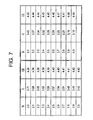
- the cast iron has a composition that includes, by weight, about 2% to about 4% Si, about 3.15% to about 3.71% C, and the balance Fe and incidental impurities as shown in FIG. 7 , and the microstructure comprises a mixture of ferrite and pearlite as a matrix having a plurality graphite nodules dispersed therein, particularly a plurality of substantially spheroidal graphite nodules disperse therein.
- silicon acts as a carbon equivalent constituent element in that it may be substituted in the crystal lattice in place of carbon in a mass ratio of approximately three to one, such that the approximately one third of the silicon by weight constitutes an equivalent weight of carbon.
- the cast iron has a carbon equivalent content, by weight, of about 4.38% to about 4.49%, as shown in FIG. 7 .
- the composition and carbon equivalents may be selected to provide a eutectic composition so as to lower the temperature at which the alloy solidifies, thereby enhancing the flow characteristics of the alloy within the mold while molten and the solidification characteristics once the temperature has dropped below the eutectic reaction isotherm.
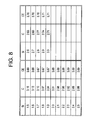
- the cast iron has a composition that includes, by weight, about 1.5% to about 3.0% Si, about 2.71% to about 3.16% C, and the balance Fe and incidental impurities as shown in FIG. 8 , and the microstructure comprises a austenite as a matrix having a plurality graphite nodules dispersed therein, particularly a plurality of substantially spheroidal graphite nodules disperse therein.
- the cast iron has a carbon equivalent content, by weight, of about 3.66% to about 3.71%, as shown in FIG. 8 .
- the composition and carbon equivalents may also be selected to provide a eutectic composition so as to lower the temperature at which the alloy solidifies, thereby enhancing the flow characteristics of the alloy within the mold while molten and the solidification characteristics once the temperature has dropped below the eutectic reaction isotherm.
- the microstructure is that of nodular cast iron having generally spheroidal graphite nodules dispersed in an iron-rich matrix, which may be ferritic or austenitic depending on the composition.
- the turbine components disclosed such as turbine casing preforms 30 or turbine nozzle diaphragm preforms 50, have an as-cast microstructure that is substantially free of defects, including microporosity associated with shrinkage and degenerate forms of graphite, particularly various degraded graphite forms, such as compacted graphite, low nodule count (oversized nodules), exploded graphite, chunky graphite, graphite floatation, nodule alignment, spiky graphite, flake graphite or carbides.
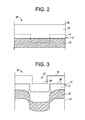
- FIGS. 2 and 5 schematically depict areas proximate an as-cast feature 22 in a cast iron turbine casing ( FIG. 2 ) and nozzle diaphragm ( FIG. 5 ) made by sand casting.
- FIGS. 3 and 6 schematically depict areas proximate an as-cast feature 22 in a cast iron turbine casing ( FIG. 3 ) and nozzle diaphragm ( FIG. 6 ) made by the lost foam method described herein.
- FIGS. 2 and 5 schematically depict areas proximate an as-cast feature 22 in a cast iron turbine casing ( FIG. 2 ) and nozzle diaphragm ( FIG. 5 ) made by the lost foam method described herein.
- the machining allowances needed to accommodate the sand casting process for the section thicknesses and size of a turbine casing and nozzle diaphragm make definition of an as-cast feature, such as a vane slot ( FIG. 2 ) or tooth seal ( FIG. 5 ), very difficult, such that there is very little or no definition of the feature in the as-cast surface 54 of the as-cast body 12. Therefore, the feature must be formed by machining and removes material from the fine grain layer 13 proximate the surface of the casting to a depth that exposes a layer 15 or subsurface region having a larger grain size due to the slower sub-surface cooling rates, and which may also contain volumetric defects, such as microporosity, and degraded graphite forms. Exposure of this layer exposes defects that may act as crack initiation sites for fatigue processes, particularly when the case/vanes and nozzle diaphragm are installed and the turbine is operating, thereby reducing the operating lifetime of these components.
- an as-cast feature such as a vane slot ( FIG.
- the machining allowances needed to accommodate the lost foam casting process for the section thicknesses and sizes of turbine casings and nozzle diaphragms allow definition of an as-cast feature, such as a vane slot in a turbine casing, and a tooth seal or lip seal in a nozzle diaphragm, , such that the feature may be defined in the as-cast surface of the as-cast body 12 to provide an as-cast vane slot profile 34 or as-cast seal profile 56 as a near-net shape feature, such that the shape of the as-cast vane slot profile 34 or as-cast seal profile 56 is substantially the same a final vane slot profile 36 or final seal profile 58, respectively.
- an as-cast feature such as a vane slot in a turbine casing, and a tooth seal or lip seal in a nozzle diaphragm
- the as-cast turbine component preform 10 has a fine grain as-cast microstructure with an average nodule count of about 100/mm 2 or smaller, and more particularly has the fine grain microstructure proximate the as-cast feature 22, such as the vane slot 32 or seal member 52.
- the fine grain microstructure proximate the as-cast feature 22 extends to a depth greater than the machining allowance, such that the fine grain microstructure remains even after the machining allowance has been removed. This provides the desirable fine grain microstructure proximate the feature 22, thereby improving the fatigue resistance of the finished turbine casing.
- the turbine components described herein In contrast to cast iron turbine components that are made by sand casting, and due to their large section thicknesses require large machining allowances and prevent the incorporation of features 22, such as vane slots 32 having as-cast slot profiles and seal members 52 having as-cast tooth profiles 56, the turbine components described herein, such as the turbine casing preform 30 and nozzle diaphragm preform 50, are cast to a near net shape and are thus also able to incorporate near-net features 22, such as near-net shape vane slot 32 or near-net shape seal member 52.
- the difference between the sand cast turbine component preforms 10 and the turbine component preforms 10 described herein may also be understood by comparing the weight of the final component to the weight of the as-cast component preform 10 as a ratio of these quantities.
- the as-cast body of the final component has a weight and the turbine component preform 10 has a weight, and the ratio of the weight of the final component to the as-cast body weight is about 0.7 or more, and more particularly about 0.8 or more, and even more particularly about 0.9 or more.
- the near-net shape turbine component preforms 10 may be made by a "lost foam process" in which a refractory coated pyrolyzable pattern is disposed in a casting flask, embedded in a gas-permeable refractory packing and appropriately gated for the introduction of the molten cast iron.
- the introduction of the molten metal pyrolyzes the pattern material so that the molten metal assumes the shape of the refractory pattern coating.
- the lost foam process uses patterns that may be machined made from expanded polystyrene or other materials, such as poly(methyl methacrylate) (PMMA) that can be pyrolyzed by the molten metal and produce less gases during removal than expanded polystyrene.
- PMMA poly(methyl methacrylate)
- the patterns are coated with a gas permeable refractory material that is porous to provide a path for the gases generated by the thermal decomposition of the pattern material to be removed as the molten metal is poured into the pattern.
- Castings of turbine component preforms 10 made using this process may be cast to a near-net shape as described herein, thereby greatly reducing or eliminating the machining allowances typical of conventional sand casting geometries.
- This method may be used to make ductile iron casting preforms of various large turbine components used in turbine engine applications, such as turbine casing preforms and turbine nozzle diaphragm preforms, including those having a mass of about 5 US tons or more.
- Sand cast turbine components usually have inferior structural integrity, including microstructural integrity, due to the large section thicknesses, slow cooling and solidification characteristics due to the substantial machining allowances added to these components.
- the large section thicknesses and machining allowances needed also have also limited the manufacture of castings with various cast-in features, particularly near-net shape features. For this reason, sand casting of cast iron has not been widely used to make turbine component preforms.
- Near net shape patterns may be CNC-machined from blocks of polystyrene or PMMA. Depending on the size and complexity of castings, these replicas can consist of multiple layers of polystyrene foam glued together.
- pattern assemblies Prior to coating the pattern assemblies with refractory slurry, they are washed with water mixed with a small amount of detergent, which helps wet the surface and prevent air pockets from forming when coated with refractory slurry.
- This slurry is generally made of fine zircon sand along with a binder of colloidal silica, hydrolyzed ethyl silicate, potassium or sodium silicate and needs to be strong enough to support the internal pressure and erosive forces exerted by the flow of molten metal and permeable enough to allow gas to escape.
- patterns with slurry coating get dried in an oven or air. These pattern assemblies are then placed in a mold cask where loose sand or resin bonded sand is molded and packed around them.
- the molds are typically incorporated with vents through which gas generated from the reaction can escape from them, not interfering with mold filling.
Landscapes
- Engineering & Computer Science (AREA)
- Mechanical Engineering (AREA)
- Chemical & Material Sciences (AREA)
- General Engineering & Computer Science (AREA)
- Materials Engineering (AREA)
- Metallurgy (AREA)
- Organic Chemistry (AREA)
- Turbine Rotor Nozzle Sealing (AREA)
Abstract
Description
- The subject matter disclosed herein relates to turbine casings and nozzle diaphragms for industrial gas and wind turbines, and more particularly, to cast iron near-net shape turbine casing and nozzle diaphragm preforms.
- Turbine casings for operating at elevated temperatures have generally been restricted to alloy steel castings or fabrications. Traditional ferritic ductile irons are less costly than alloy steels, but typically have had an inadequate combination of properties, thereby precluding their use in advanced gas turbine compressor discharge and turbine shell casings and other components, such as nozzle diaphragms. One of the limiting aspects has been related to the fact that these components have been made as sand castings. Finish machined conventional sand castings used for turbine components, such as casings and nozzle diaphragms, must have complex features added to them by machining. Due to the nature of conventional sand casting processes, which are currently used to cast the cast iron casings and nozzle diaphragms used in gas turbines and wind turbines, these features, including vane slots, bolt holes and various seals, depend on extensive machining upon completion of the casting process. It is not uncommon to find that the machining processes costs considerably more than the casting. However, from a metallurgical perspective, increasing the casting size to provide machining allowances significantly decreases the structural integrity of the cast parts. Larger castings with more machining allowances take longer to solidify and cool, which can cause degenerate graphite formation in ductile iron castings. Further, the larger castings typically require more risers or reservoirs for the molten metal to increase castability. However, the addition of more risers also tends to increase the likelihood of producing degenerate forms of graphite, which are known to reduce the elongation and fatigue properties resulting in reduced operating lifetimes. Also, desirable fine grain structures are typically found adjacent to as-cast surfaces. However, current sand cast iron components used in gas and wind turbines are heavily machined removing the desirable fine grain structures and frequently exposing undesirable internal microstructural features and volumetric defects, such as internal microporosity and degenerate graphite forms. Therefore, it is desirable to provide cast iron turbine components that significantly reduce or eliminate machining operations, provide desirable fine grain microstructures and avoid the creation and exposure of undesirable internal microstructural features.
- According to one aspect, the invention resides in a turbine component preform including an as-cast body comprising a partially cylindrical wall section of a turbine component, the wall section having an inner surface and an outer surface and an as-cast circumferentially-extending feature formed in the wall section on one of the inner surface, outer surface or both. The turbine component preform may comprise a turbine casing preform including a vane slot formed on the inner surface of the wall section.
- Alternatively, the turbine component preform may complete a turbine nozzle diaphragm preform including an as-cast, circumferentially-extending seal member projecting from one of the outer surface or inner surface.
- Embodiments of the present invention will now be described, by way of example only, with reference to the accompanying drawings in which:
-
FIG. 1 is a perspective view of an exemplary embodiment of a turbine component preform in the form of a turbine casing preform as disclosed herein; -
FIG. 2 is as a cross-sectional view illustrating the as-cast and final profiles of a related art turbine component feature casting in the form of a vane slot made by sand casting; -
FIG. 3 is as a cross-sectional view of section 3-3 ofFIG. 1 that illustrates as-cast and final profiles of an exemplary embodiment of turbine component feature in the form of a near-net shape vane slot as disclosed herein; -
FIG. 4 is a perspective view of another exemplary embodiment of a turbine component preform in the form of a turbine nozzle diaphragm preform as disclosed herein; -
FIG. 5 is as a cross-sectional view illustrating the as-cast and final profiles of a related art turbine component feature casting in the form of tooth seals made by sand casting; -
FIG. 6 is as a cross-sectional view of section 6-6 ofFIG. 4 that illustrates as-cast and final profiles of an exemplary embodiment of turbine component feature in the form of a near-net shape tooth seals as disclosed herein; -
FIG. 7 is a table illustrating exemplary ferritic/pearlitic ductile iron compositions as disclosed herein; and -
FIG. 8 is a table illustrating exemplary austenitic ductile iron compositions as disclosed herein; - The detailed description explains embodiments of the invention, together with advantages and features, by way of example with reference to the drawings.
- Referring to
Figures 1-8 , an as-castturbine component preform 10 is disclosed. The as-castturbine component preform 10 may be used to make various turbine components for any suitable type of industrial turbine engine, particularly various industrial gas turbine and wind turbine engines, and is particularly suited for making turbine components having large sizes and section thicknesses. The as-castturbine component preform 10 may be a preform for any desired turbine component, and is particularly suited as a preform for a cylindrical or partially cylindrical turbine component, such as a turbine casing preform 30 and turbine nozzle diaphragm preform 50. Theturbine component preform 10 includes an as-cast body 12 comprising a partiallycylindrical wall section 14. Thewall section 14 is referred to as partially cylindrical so as to encompass any axially extending circumferential portion or segment of a cylinder, including semi-cylinder or full cylinder configurations, as well as all manner of circumferential cylindrical segments. Thewall section 14 has aninner surface 16 disposed closer to thelongitudinal axis 18 of the cylinder and anouter surface 20 disposed away from theaxis 18. Thewall section 14 includes a circumferentially-extending, near-net shape as-cast feature formed in thewall section 14 on one of theinner surface 16,outer surface 20 or both. Exemplary embodiments include at least a partially cylindrical, as-cast turbine casing preform 30 having at least one integral, as-cast, near-net shape, circumferentially-extending vane slot 32 formed on theinner surface 16 and a partially cylindrical, as-cast turbine nozzle diaphragm preform 50 having an as-cast, protruding, circumferentially-extendingseal 52 formed oninner surface 16,outer surface 20 or both, as described herein. - As illustrated in
FIGS. 1 and3 , in an exemplary embodiment, a turbine casing preform 30 is disclosed. Theturbine casing 30 may include any aspect of the turbine casing, including compressor cases, compressor discharge cases and turbine shells. The turbine casing preform 30 includes an as-cast body 12. The as-cast casing body may include a partiallycylindrical wall section 14 of a turbine casing preform 30. In the embodiment ofFIGS. 1 and3 , a cylindrical (e.g., fully cylindrical)wall section 14 is shown comprising twosemi-cylindrical wall sections 14. In other embodiments, thecylindrical wall section 14 may be only a partiallycylindrical wall section 14 of a casing preform (not shown). Thewall section 14 has aninner surface 16 disposed closer to thelongitudinal axis 18 of the cylinder and anouter surface 20 disposed away from theaxis 18. The as-cast wall section 14 also includes an as-cast, circumferentially-extendingfeature 22 in the form of an as-cast, circumferentially-extending vane slot 32 formed in thewall section 14 on theinner surface 16. While it may include as few as one as-cast, circumferentially-extending vane slot 32, it may also include a plurality of as-cast, circumferentially-extending vane slots 32 that are spaced from one another along thelongitudinal axis 18 of the casing preform 30. - The vane slot 32 may have any suitable as-
cast slot profile 34. In an exemplary embodiment, the circumferentially-extending vane slot 32 has an as-cast slot profile 34 or shape that is substantially the same as afinal slot profile 36 or shape, as shown inFIG. 3 . For example, if thefinal profile 36 of the vane slot 32 comprises a rectangular or alternately an inverted T-shape dovetail profile 36, the as-cast profile 34 may also comprise a rectangular or alternately an inverted T-shape dovetail profile 36, i.e., a generally rectangular profile (transverse to the circumferential direction) slot where the bottom portion of the rectangular slot has an increased width, thereby providing a wider channel at the bottom of the slot. The as-cast feature 22 may have an as-cast slot profile 34 that comprises afinal profile 36, i.e., that may be used directly without machining, grinding or other finishing operations. It may also have an as-cast slot profile 34 that approximates thefinal slot profile 36 or shape with sufficient material to provide a material allowance sufficient for finishing operations. - As illustrated in
FIGS. 4 and6 , in another exemplary embodiment, a turbinenozzle diaphragm preform 50 is disclosed. The turbinenozzle diaphragm preform 50 includes an as-castbody 12. The as-cast body 12 includes a partiallycylindrical wall section 14 of a turbine nozzle diaphragm preform 50. In one embodiment, the partiallycylindrical wall section 14 may comprise a semi-cylindrical or fullycylindrical wall section 14. The as-cast wall section 14 also includes an as-cast, circumferentially-extendingfeature 22 in the form of an as-cast, circumferentially-extendingseal member 52 formed in and projecting from thewall section 14 on theinner surface 16,outer surface 20, or both surfaces. While it may include only one as-cast, circumferentially-extending seal member projecting from thewall section 14, the circumferentially-extendingseal member 52 may include a plurality of circumferentially-extendingseal members 52. In one embodiment as shown inFIG. 6 , the projectingseal member 52 comprises a plurality ofseal teeth 54 projecting radially inwardly from theinner surface 16 of the as-cast body 12. Other circumferentially-extending features, such asvarious shoulders 55 andslots 57 formed in or on theinner surface 16,outer surface 20, or both. - The projecting
seal member 52 may have any suitable as-cast seal profile 56. In an exemplary embodiment, the circumferentially-extendingseal member 52 has an as-cast seal profile 56 or shape that is substantially the same as afinal seal profile 58 or shape, as shown inFIG. 6 . For example, if thefinal profile 58 of theseal member 52 comprises a toothshaped profile 60, the as-cast profile 56 may also comprise a plurality ofseal teeth 60 having alternating sizes in a pattern, such as an alternating arrangement of shorter andlonger seal teeth 60. The as-cast feature 22 may have an as-castseal member profile 56 that comprises afinal profile 58, i.e., that may be used directly without machining, grinding or other finishing operations. It may also have an as-castseal member profile 56 that approximates thefinal seal profile 58 or shape with sufficient material to provide a material allowance sufficient for finishing operations as shown inFIG. 6 . In one embodiment, the turbinenozzle diaphragm preform 50 has a partially-cylindrical wall section 14 that has a generallyU-shaped profile 62 comprising a base 64 having opposed ends and twolegs 66, with eachleg 66 extending radially outwardly from one of the opposed ends 68, and a plurality of circumferentially extendingseal teeth 60 project radially inwardly from aninner surface 16 of the base 64. Thelegs 66 may also include an outwardly or an inwardly projectinglip seal 70, or both, on any portion of theleg 66, particularly on an end 72 away from the base 64. The projectingseal member 52 may have any suitable as -cast seal profile 56, including an as-cast seal profile 56 that is substantially the same as thefinal seal profile 58. In one embodiment, the plurality of circumferentially-extendingseal teeth 60 may have an as-cast tooth profile 74 that is substantially the same as afinal tooth profile 76. In another embodiment, circumferentially- extendinglip seal 70 may also have an as-cast lip seal profile that is substantially the same as a final lip profile, and would be illustrated similarly to that of the tooth seal profiles ofFIG. 6 . - In the various embodiments, the turbine component preforms 10 disclosed, such as turbine casing preforms 30 or turbine nozzle diaphragm preforms 50, have an as-
cast body 12 formed from cast iron, particularly various grades of ductile iron. In one exemplary embodiment, the cast iron has a composition that includes, by weight, about 2% to about 4% Si, about 3.15% to about 3.71% C, and the balance Fe and incidental impurities as shown inFIG. 7 , and the microstructure comprises a mixture of ferrite and pearlite as a matrix having a plurality graphite nodules dispersed therein, particularly a plurality of substantially spheroidal graphite nodules disperse therein. In ductile iron, silicon acts as a carbon equivalent constituent element in that it may be substituted in the crystal lattice in place of carbon in a mass ratio of approximately three to one, such that the approximately one third of the silicon by weight constitutes an equivalent weight of carbon. In the composition described above, the cast iron has a carbon equivalent content, by weight, of about 4.38% to about 4.49%, as shown inFIG. 7 . For the ferritic/pearlitic compositions, the composition and carbon equivalents may be selected to provide a eutectic composition so as to lower the temperature at which the alloy solidifies, thereby enhancing the flow characteristics of the alloy within the mold while molten and the solidification characteristics once the temperature has dropped below the eutectic reaction isotherm. - In another exemplary embodiment, the cast iron has a composition that includes, by weight, about 1.5% to about 3.0% Si, about 2.71% to about 3.16% C, and the balance Fe and incidental impurities as shown in
FIG. 8 , and the microstructure comprises a austenite as a matrix having a plurality graphite nodules dispersed therein, particularly a plurality of substantially spheroidal graphite nodules disperse therein. In the composition described above, the cast iron has a carbon equivalent content, by weight, of about 3.66% to about 3.71%, as shown inFIG. 8 . For the austenitic compositions, the composition and carbon equivalents may also be selected to provide a eutectic composition so as to lower the temperature at which the alloy solidifies, thereby enhancing the flow characteristics of the alloy within the mold while molten and the solidification characteristics once the temperature has dropped below the eutectic reaction isotherm. - As noted above, the microstructure is that of nodular cast iron having generally spheroidal graphite nodules dispersed in an iron-rich matrix, which may be ferritic or austenitic depending on the composition. In one embodiment, the turbine components disclosed, such as turbine casing preforms 30 or turbine nozzle diaphragm preforms 50, have an as-cast microstructure that is substantially free of defects, including microporosity associated with shrinkage and degenerate forms of graphite, particularly various degraded graphite forms, such as compacted graphite, low nodule count (oversized nodules), exploded graphite, chunky graphite, graphite floatation, nodule alignment, spiky graphite, flake graphite or carbides. This may be seen, for example, by comparing
FIGS. 2 and5 withFIGS. 3 and6 .FIGS. 2 and5 schematically depict areas proximate an as-cast feature 22 in a cast iron turbine casing (FIG. 2 ) and nozzle diaphragm (FIG. 5 ) made by sand casting.FIGS. 3 and6 schematically depict areas proximate an as-cast feature 22 in a cast iron turbine casing (FIG. 3 ) and nozzle diaphragm (FIG. 6 ) made by the lost foam method described herein. InFIGS. 2 and5 , the machining allowances needed to accommodate the sand casting process for the section thicknesses and size of a turbine casing and nozzle diaphragm make definition of an as-cast feature, such as a vane slot (FIG. 2 ) or tooth seal (FIG. 5 ), very difficult, such that there is very little or no definition of the feature in the as-cast surface 54 of the as-cast body 12. Therefore, the feature must be formed by machining and removes material from thefine grain layer 13 proximate the surface of the casting to a depth that exposes alayer 15 or subsurface region having a larger grain size due to the slower sub-surface cooling rates, and which may also contain volumetric defects, such as microporosity, and degraded graphite forms. Exposure of this layer exposes defects that may act as crack initiation sites for fatigue processes, particularly when the case/vanes and nozzle diaphragm are installed and the turbine is operating, thereby reducing the operating lifetime of these components. - In contrast, in
FIGS. 3 and6 , the machining allowances needed to accommodate the lost foam casting process for the section thicknesses and sizes of turbine casings and nozzle diaphragms allow definition of an as-cast feature, such as a vane slot in a turbine casing, and a tooth seal or lip seal in a nozzle diaphragm, , such that the feature may be defined in the as-cast surface of the as-cast body 12 to provide an as-castvane slot profile 34 or as-cast seal profile 56 as a near-net shape feature, such that the shape of the as-castvane slot profile 34 or as-cast seal profile 56 is substantially the same a finalvane slot profile 36 orfinal seal profile 58, respectively. In this case, it is not necessary to form the feature almost entirely by machining and remove material from thefine grain layer 13 proximate the surface of the casting to a depth that exposes thelayer 15 having a larger grain size and containing volumetric defects, such as microporosity, and degraded graphite forms. This tends to reduce defects that may act as crack initiation sites for fatigue processes and improve the operating lifetimes of theturbine casings 30 andnozzle diaphragms 50 disclosed herein. - In an exemplary embodiment, the as-cast
turbine component preform 10 has a fine grain as-cast microstructure with an average nodule count of about 100/mm2 or smaller, and more particularly has the fine grain microstructure proximate the as-cast feature 22, such as the vane slot 32 orseal member 52. The fine grain microstructure proximate the as-cast feature 22 extends to a depth greater than the machining allowance, such that the fine grain microstructure remains even after the machining allowance has been removed. This provides the desirable fine grain microstructure proximate thefeature 22, thereby improving the fatigue resistance of the finished turbine casing. - In contrast to cast iron turbine components that are made by sand casting, and due to their large section thicknesses require large machining allowances and prevent the incorporation of
features 22, such as vane slots 32 having as-cast slot profiles andseal members 52 having as-cast tooth profiles 56, the turbine components described herein, such as theturbine casing preform 30 andnozzle diaphragm preform 50, are cast to a near net shape and are thus also able to incorporate near-net features 22, such as near-net shape vane slot 32 or near-netshape seal member 52. The difference between the sand cast turbine component preforms 10 and the turbine component preforms 10 described herein may also be understood by comparing the weight of the final component to the weight of the as-cast component preform 10 as a ratio of these quantities. The as-cast body of the final component has a weight and theturbine component preform 10 has a weight, and the ratio of the weight of the final component to the as-cast body weight is about 0.7 or more, and more particularly about 0.8 or more, and even more particularly about 0.9 or more. - The near-net shape turbine component preforms 10 may be made by a "lost foam process" in which a refractory coated pyrolyzable pattern is disposed in a casting flask, embedded in a gas-permeable refractory packing and appropriately gated for the introduction of the molten cast iron. The introduction of the molten metal pyrolyzes the pattern material so that the molten metal assumes the shape of the refractory pattern coating. The lost foam process uses patterns that may be machined made from expanded polystyrene or other materials, such as poly(methyl methacrylate) (PMMA) that can be pyrolyzed by the molten metal and produce less gases during removal than expanded polystyrene. The patterns are coated with a gas permeable refractory material that is porous to provide a path for the gases generated by the thermal decomposition of the pattern material to be removed as the molten metal is poured into the pattern. Castings of turbine component preforms 10 made using this process may be cast to a near-net shape as described herein, thereby greatly reducing or eliminating the machining allowances typical of conventional sand casting geometries. This method may be used to make ductile iron casting preforms of various large turbine components used in turbine engine applications, such as turbine casing preforms and turbine nozzle diaphragm preforms, including those having a mass of about 5 US tons or more. Sand cast turbine components usually have inferior structural integrity, including microstructural integrity, due to the large section thicknesses, slow cooling and solidification characteristics due to the substantial machining allowances added to these components. The large section thicknesses and machining allowances needed also have also limited the manufacture of castings with various cast-in features, particularly near-net shape features. For this reason, sand casting of cast iron has not been widely used to make turbine component preforms. Near net shape patterns may be CNC-machined from blocks of polystyrene or PMMA. Depending on the size and complexity of castings, these replicas can consist of multiple layers of polystyrene foam glued together. Prior to coating the pattern assemblies with refractory slurry, they are washed with water mixed with a small amount of detergent, which helps wet the surface and prevent air pockets from forming when coated with refractory slurry. This slurry is generally made of fine zircon sand along with a binder of colloidal silica, hydrolyzed ethyl silicate, potassium or sodium silicate and needs to be strong enough to support the internal pressure and erosive forces exerted by the flow of molten metal and permeable enough to allow gas to escape. Then patterns with slurry coating get dried in an oven or air. These pattern assemblies are then placed in a mold cask where loose sand or resin bonded sand is molded and packed around them. The molds are typically incorporated with vents through which gas generated from the reaction can escape from them, not interfering with mold filling. Once the pattern with the refractory coating has been placed into the mold cask and the mold material, such as loose sand or resin bonded sand has been placed around the pattern, the cast iron is poured into the foam pattern thereby pyrolizing the foam and forming the
turbine component preform 10 upon solidification of the cast iron. - While the invention has been described in detail in connection with only a limited number of embodiments, it should be readily understood that the invention is not limited to such disclosed embodiments. Rather, the invention can be modified to incorporate any number of variations, alterations, substitutions or equivalent arrangements not heretofore described, but which are commensurate with the spirit and scope of the invention. Additionally, while various embodiments of the invention have been described, it is to be understood that aspects of the invention may include only some of the described embodiments. Accordingly, the invention is not to be seen as limited by the foregoing description, but is only limited by the scope of the appended claims.
Claims (15)
- A turbine component preform (30,50), comprising:an as-cast body (12) comprising a partially cylindrical wall section (14) of a turbine component, the wall section having an inner surface (16) and an outer surface (20); andan as-cast circumferentially-extending feature (22), formed in the wall section (14) on one of the inner surface (16) or outer surface (20 or both.
- The turbine component preform (30), of claim 1, wherein the turbine component is a turbine casing and wherein the as-cast circumferentially-extended feature (22) comprises:a vane slot (32) formed in the wall section on the inner surface (16).
- The turbine component preform (30) of claim 2, wherein the vane slot (32) has an as-cast slot profile (34) that is substantially the same as a final slot profile.
- The turbine component preform of claim 2 or 3, wherein the vane slot (32) comprises a plurality of vane slots (32) that are spaced from one another along a longitudinal axis of the preform (30).
- The turbine component preform (30) of any of claims 1 to 4, wherein the as-cast body (12) comprises a cast iron.
- The turbine component preform (30) of claim 5, wherein the cast iron comprises, by weight, about 2% to about 4% Si, about 3.15% to about 3.71% C, and the balance Fe and incidental impurities.
- The turbine component preform (30) of any of claims 1 to 6, wherein the as cast body (12) has a weight and a final body formed from the as-cast body (12) has a weight, and the ratio of the weight of the as-cast body (12) to the weight of the final body is about 0.7 or more.
- The turbine component preform (30,50) of claim 1, wherein the turbine component comprises: a turbine nozzle diaphragm (50), and wherein the as-cast circumferentially-extending feature comprises a seal member projecting from one of the outer surface (20) or inner surface (16).
- The turbine component preform (50) of claim 8, wherein the seal member (52) comprises a plurality of seal teeth (54) projecting radially inwardly from the inner surface of the as-cast body (12).
- The turbine component preform (50) of claim 8 or 9, wherein the partially-cylindrical wall section has a generally U-shaped profile (62) comprising a base (64) having opposed ends (68) and two legs (66), each leg extending radially outwardly from one of the opposed ends (68), the plurality of seal teeth (60) project radially inwardly from an inner surface of the base (64).
- The turbine nozzle diaphragm preform of claim 10, wherein one of the legs has an outwardly projecting lip seal on an end away from the base.
- The turbine component preform (50) of any of claims 8 to 11, wherein the as-cast body (12) comprises a cast iron having a composition comprising, by weight, about 1.5% to about 3% Si, about 2.71% to about 3.16% C and the balance Fe and incidental impurities, and having a microstructure comprising austenite as a matrix and a plurality of graphite nodules dispersed in the matrix.
- The turbine component preform (50) of any of claims 8 to 11, wherein the as-cast body (12) comprises a cast iron having a composition comprising, by weight, about 2% to about 4% Si, about 3.15% to about 3.71% C and the balance Fe and incidental impurities, and having a microstructure comprising a mixture of ferrite and pearlite as a matrix and a plurality of graphite nodules dispersed in the matrix.
- The turbine component preform of any of claims 9 to 13, wherein the plurality of seal teeth have an as-cast tooth profile that is substantially the same as a final tooth profile.
- The turbine component preform of any of claims 8 to 14, wherein the outwardly extending lip seal has an as-cast lip seal profile that is substantially the same as a final lip seal profile.
Priority Applications (1)
| Application Number | Priority Date | Filing Date | Title |
|---|---|---|---|
| PL12160407T PL2503108T3 (en) | 2011-03-23 | 2012-03-20 | Cast turbine casing and nozzle diaphragm preforms |
Applications Claiming Priority (1)
| Application Number | Priority Date | Filing Date | Title |
|---|---|---|---|
| US13/069,471 US8979488B2 (en) | 2011-03-23 | 2011-03-23 | Cast turbine casing and nozzle diaphragm preforms |
Publications (3)
| Publication Number | Publication Date |
|---|---|
| EP2503108A2 true EP2503108A2 (en) | 2012-09-26 |
| EP2503108A3 EP2503108A3 (en) | 2017-06-07 |
| EP2503108B1 EP2503108B1 (en) | 2020-04-29 |
Family
ID=45952868
Family Applications (1)
| Application Number | Title | Priority Date | Filing Date |
|---|---|---|---|
| EP12160407.8A Not-in-force EP2503108B1 (en) | 2011-03-23 | 2012-03-20 | Cast turbine casing and nozzle diaphragm preforms |
Country Status (5)
| Country | Link |
|---|---|
| US (1) | US8979488B2 (en) |
| EP (1) | EP2503108B1 (en) |
| JP (1) | JP6043075B2 (en) |
| CN (1) | CN102691535A (en) |
| PL (1) | PL2503108T3 (en) |
Cited By (1)
| Publication number | Priority date | Publication date | Assignee | Title |
|---|---|---|---|---|
| FR3050670A1 (en) * | 2016-04-28 | 2017-11-03 | Snecma | VIROLE AND METHOD FOR MANUFACTURING A CASE COMPRISING A VIROLE |
Families Citing this family (3)
| Publication number | Priority date | Publication date | Assignee | Title |
|---|---|---|---|---|
| USD789180S1 (en) * | 2015-12-23 | 2017-06-13 | Roger Webb | Modular furniture part |
| US10828732B2 (en) * | 2017-04-27 | 2020-11-10 | General Electric Company | Treated turbine diaphragm and method for treating a turbine diaphragm |
| CN116045310B (en) * | 2023-01-29 | 2024-09-06 | 中国航发沈阳发动机研究所 | Combustion chamber pre-rotation air supply device with ash removal function |
Family Cites Families (25)
| Publication number | Priority date | Publication date | Assignee | Title |
|---|---|---|---|---|
| JPS4941718A (en) * | 1972-03-16 | 1974-04-19 | ||
| US3741680A (en) * | 1972-04-05 | 1973-06-26 | Avco Corp | Split housing piloting device |
| US4137006A (en) * | 1977-01-26 | 1979-01-30 | K B Southern, Inc. | Composite horizontally split casing |
| JPS5479316A (en) * | 1977-12-05 | 1979-06-25 | Hitachi Ltd | Gas turbine casing |
| US4305192A (en) * | 1978-09-27 | 1981-12-15 | Becker John H | Method of fabricating a composite horizontally split casing |
| US4208777A (en) * | 1978-11-27 | 1980-06-24 | United Technologies Corporation | Method for manufacturing a split engine casing from a cylinder |
| JPS56162300A (en) * | 1980-05-16 | 1981-12-14 | Hitachi Ltd | Manufacture of casing for gas-turbine compressor |
| JPS6053736B2 (en) * | 1981-10-05 | 1985-11-27 | 日産自動車株式会社 | Heat-resistant spheroidal graphite cast iron |
| US4520858A (en) | 1983-11-02 | 1985-06-04 | General Motors Corporation | Chill-enhanced lost foam casting process |
| US5031685A (en) | 1988-06-03 | 1991-07-16 | Outboard Marine Corporation | Internal combustion engine and method for making the same |
| US5054537A (en) | 1988-06-03 | 1991-10-08 | Outboard Marine Corporation | Lost foam pattern assembly for V-block engine |
| US5000244A (en) | 1989-12-04 | 1991-03-19 | General Motors Corporation | Lost foam casting of dual alloy engine block |
| US5109668A (en) | 1991-03-07 | 1992-05-05 | Brunswick Corporation | Marine exhaust manifold and elbow |
| JP2867735B2 (en) * | 1991-05-09 | 1999-03-10 | 株式会社日立製作所 | Hermetic scroll compressor |
| US5609698A (en) * | 1995-01-23 | 1997-03-11 | General Electric Company | Processing of gamma titanium-aluminide alloy using a heat treatment prior to deformation processing |
| US5846050A (en) * | 1997-07-14 | 1998-12-08 | General Electric Company | Vane sector spring |
| US6506018B1 (en) * | 1999-01-25 | 2003-01-14 | Elliott Turbomachinery Co., Inc. | Casing design for rotating machinery and method for manufacture thereof |
| JP2001068331A (en) * | 1999-08-27 | 2001-03-16 | Toshiba Corp | Method of manufacturing superconducting coil disk |
| JP2001107922A (en) * | 1999-10-08 | 2001-04-17 | Mitsubishi Heavy Ind Ltd | Fastening structure of flangeless casing |
| GB0005740D0 (en) * | 2000-03-10 | 2000-05-03 | Downhole Products Plc | Centraliser |
| JP3937690B2 (en) * | 2000-05-24 | 2007-06-27 | 株式会社豊田自動織機 | Compressor |
| JP3592664B2 (en) * | 2001-11-08 | 2004-11-24 | 株式会社東芝 | Method for manufacturing turbine casing |
| JP4412081B2 (en) * | 2004-07-07 | 2010-02-10 | 株式会社日立製作所 | Gas turbine and gas turbine cooling method |
| US8128353B2 (en) * | 2008-09-30 | 2012-03-06 | General Electric Company | Method and apparatus for matching the thermal mass and stiffness of bolted split rings |
| US20100322813A1 (en) * | 2009-06-23 | 2010-12-23 | General Electric Company | SiMo DUCTILE IRON CASTINGS IN GAS TURBINE APPLICATIONS |
-
2011
- 2011-03-23 US US13/069,471 patent/US8979488B2/en active Active
-
2012
- 2012-03-15 JP JP2012058056A patent/JP6043075B2/en not_active Expired - Fee Related
- 2012-03-20 PL PL12160407T patent/PL2503108T3/en unknown
- 2012-03-20 EP EP12160407.8A patent/EP2503108B1/en not_active Not-in-force
- 2012-03-23 CN CN2012100935310A patent/CN102691535A/en active Pending
Non-Patent Citations (1)
| Title |
|---|
| None |
Cited By (1)
| Publication number | Priority date | Publication date | Assignee | Title |
|---|---|---|---|---|
| FR3050670A1 (en) * | 2016-04-28 | 2017-11-03 | Snecma | VIROLE AND METHOD FOR MANUFACTURING A CASE COMPRISING A VIROLE |
Also Published As
| Publication number | Publication date |
|---|---|
| PL2503108T3 (en) | 2020-09-21 |
| JP2012202405A (en) | 2012-10-22 |
| EP2503108A3 (en) | 2017-06-07 |
| EP2503108B1 (en) | 2020-04-29 |
| US8979488B2 (en) | 2015-03-17 |
| CN102691535A (en) | 2012-09-26 |
| US20120243981A1 (en) | 2012-09-27 |
| JP6043075B2 (en) | 2016-12-14 |
Similar Documents
| Publication | Publication Date | Title |
|---|---|---|
| EP2503108B1 (en) | Cast turbine casing and nozzle diaphragm preforms | |
| CN102282395A (en) | Steel material composition for producing piston rings and cylinder sleeves | |
| KR20120024561A (en) | Nitratable steel piston rings and steel cylindrical sleeves, and casting method for the production thereof | |
| PT2052094T (en) | Steel material having a high silicon content for producing piston rings and cylinder sleeves | |
| CN102272491B (en) | Piston rings and cylinder liners | |
| JP2012518764A (en) | Steel composition for manufacturing piston rings and cylinder sleeves | |
| CN102876962A (en) | Method for manufacturing bainite ductile cast iron piston ring | |
| KR100265542B1 (en) | Scroll member, casting method of scroll member, inoculation method and pattern of molten metal | |
| CN102265069B (en) | piston ring | |
| MXPA96003277A (en) | Method for molding a chamber of section decrecie | |
| KR20120022827A (en) | Nitratable steel material composition for producing piston rings and cylindrical sleeves | |
| CN105772635B (en) | A kind of production method of cylinder liner | |
| JP2002309935A (en) | Exhaust system parts of heat-resisting steel | |
| US8662144B2 (en) | Methods of casting scroll compressor components | |
| US20120051898A1 (en) | Wind turbine component having a lightweight structure | |
| CN102534354A (en) | Alloy gray cast iron piston ring as well as manufacturing method and special template thereof | |
| JPH0649582A (en) | Method for casting high wear resistant high chromium cast iron | |
| JPS59147769A (en) | Production of composite casting | |
| EP4444486A1 (en) | Mold for manufacturing an engine casting part for a vehicle from vermicular cast iron alloy, process for manufacturing an engine casting part for a vehicle from vermicular cast iron alloy, and process for assembling a vehicle engine by the combination of parts made from vermicular cast iron alloy and parts made from composites | |
| US20130032303A1 (en) | Wind turbine component having a lightweight structure | |
| JP2016064428A (en) | Fire proof ceramic filler for initial layer slurry and precision casting mold using the same | |
| Mkumbo et al. | Linear contraction of grey iron sand castings | |
| JPH04200951A (en) | Manufacture of wear resistance high cr cast iron products and its mold | |
| Kiran et al. | Structural analysis of grey iron nose leg component produced by lost foam casting | |
| Green-Spikesley | Investment casting |
Legal Events
| Date | Code | Title | Description |
|---|---|---|---|
| PUAI | Public reference made under article 153(3) epc to a published international application that has entered the european phase |
Free format text: ORIGINAL CODE: 0009012 |
|
| AK | Designated contracting states |
Kind code of ref document: A2 Designated state(s): AL AT BE BG CH CY CZ DE DK EE ES FI FR GB GR HR HU IE IS IT LI LT LU LV MC MK MT NL NO PL PT RO RS SE SI SK SM TR |
|
| AX | Request for extension of the european patent |
Extension state: BA ME |
|
| PUAL | Search report despatched |
Free format text: ORIGINAL CODE: 0009013 |
|
| AK | Designated contracting states |
Kind code of ref document: A3 Designated state(s): AL AT BE BG CH CY CZ DE DK EE ES FI FR GB GR HR HU IE IS IT LI LT LU LV MC MK MT NL NO PL PT RO RS SE SI SK SM TR |
|
| AX | Request for extension of the european patent |
Extension state: BA ME |
|
| RIC1 | Information provided on ipc code assigned before grant |
Ipc: B22D 25/02 20060101ALI20170428BHEP Ipc: F01D 25/24 20060101AFI20170428BHEP Ipc: C22C 37/10 20060101ALI20170428BHEP Ipc: F01D 9/02 20060101ALI20170428BHEP Ipc: B22D 23/00 20060101ALI20170428BHEP |
|
| PUAL | Search report despatched |
Free format text: ORIGINAL CODE: 0009013 |
|
| STAA | Information on the status of an ep patent application or granted ep patent |
Free format text: STATUS: REQUEST FOR EXAMINATION WAS MADE |
|
| 17P | Request for examination filed |
Effective date: 20171207 |
|
| RBV | Designated contracting states (corrected) |
Designated state(s): AL AT BE BG CH CY CZ DE DK EE ES FI FR GB GR HR HU IE IS IT LI LT LU LV MC MK MT NL NO PL PT RO RS SE SI SK SM TR |
|
| STAA | Information on the status of an ep patent application or granted ep patent |
Free format text: STATUS: EXAMINATION IS IN PROGRESS |
|
| 17Q | First examination report despatched |
Effective date: 20180405 |
|
| GRAP | Despatch of communication of intention to grant a patent |
Free format text: ORIGINAL CODE: EPIDOSNIGR1 |
|
| STAA | Information on the status of an ep patent application or granted ep patent |
Free format text: STATUS: GRANT OF PATENT IS INTENDED |
|
| INTG | Intention to grant announced |
Effective date: 20191127 |
|
| GRAS | Grant fee paid |
Free format text: ORIGINAL CODE: EPIDOSNIGR3 |
|
| GRAA | (expected) grant |
Free format text: ORIGINAL CODE: 0009210 |
|
| STAA | Information on the status of an ep patent application or granted ep patent |
Free format text: STATUS: THE PATENT HAS BEEN GRANTED |
|
| AK | Designated contracting states |
Kind code of ref document: B1 Designated state(s): AL AT BE BG CH CY CZ DE DK EE ES FI FR GB GR HR HU IE IS IT LI LT LU LV MC MK MT NL NO PL PT RO RS SE SI SK SM TR |
|
| REG | Reference to a national code |
Ref country code: GB Ref legal event code: FG4D |
|
| REG | Reference to a national code |
Ref country code: CH Ref legal event code: EP |
|
| REG | Reference to a national code |
Ref country code: AT Ref legal event code: REF Ref document number: 1263645 Country of ref document: AT Kind code of ref document: T Effective date: 20200515 |
|
| REG | Reference to a national code |
Ref country code: DE Ref legal event code: R096 Ref document number: 602012069622 Country of ref document: DE |
|
| REG | Reference to a national code |
Ref country code: IE Ref legal event code: FG4D |
|
| REG | Reference to a national code |
Ref country code: NL Ref legal event code: MP Effective date: 20200429 |
|
| REG | Reference to a national code |
Ref country code: LT Ref legal event code: MG4D |
|
| PG25 | Lapsed in a contracting state [announced via postgrant information from national office to epo] |
Ref country code: NO Free format text: LAPSE BECAUSE OF FAILURE TO SUBMIT A TRANSLATION OF THE DESCRIPTION OR TO PAY THE FEE WITHIN THE PRESCRIBED TIME-LIMIT Effective date: 20200729 Ref country code: LT Free format text: LAPSE BECAUSE OF FAILURE TO SUBMIT A TRANSLATION OF THE DESCRIPTION OR TO PAY THE FEE WITHIN THE PRESCRIBED TIME-LIMIT Effective date: 20200429 Ref country code: SE Free format text: LAPSE BECAUSE OF FAILURE TO SUBMIT A TRANSLATION OF THE DESCRIPTION OR TO PAY THE FEE WITHIN THE PRESCRIBED TIME-LIMIT Effective date: 20200429 Ref country code: GR Free format text: LAPSE BECAUSE OF FAILURE TO SUBMIT A TRANSLATION OF THE DESCRIPTION OR TO PAY THE FEE WITHIN THE PRESCRIBED TIME-LIMIT Effective date: 20200730 Ref country code: PT Free format text: LAPSE BECAUSE OF FAILURE TO SUBMIT A TRANSLATION OF THE DESCRIPTION OR TO PAY THE FEE WITHIN THE PRESCRIBED TIME-LIMIT Effective date: 20200831 Ref country code: IS Free format text: LAPSE BECAUSE OF FAILURE TO SUBMIT A TRANSLATION OF THE DESCRIPTION OR TO PAY THE FEE WITHIN THE PRESCRIBED TIME-LIMIT Effective date: 20200829 Ref country code: FI Free format text: LAPSE BECAUSE OF FAILURE TO SUBMIT A TRANSLATION OF THE DESCRIPTION OR TO PAY THE FEE WITHIN THE PRESCRIBED TIME-LIMIT Effective date: 20200429 |
|
| PG25 | Lapsed in a contracting state [announced via postgrant information from national office to epo] |
Ref country code: BG Free format text: LAPSE BECAUSE OF FAILURE TO SUBMIT A TRANSLATION OF THE DESCRIPTION OR TO PAY THE FEE WITHIN THE PRESCRIBED TIME-LIMIT Effective date: 20200729 Ref country code: HR Free format text: LAPSE BECAUSE OF FAILURE TO SUBMIT A TRANSLATION OF THE DESCRIPTION OR TO PAY THE FEE WITHIN THE PRESCRIBED TIME-LIMIT Effective date: 20200429 Ref country code: RS Free format text: LAPSE BECAUSE OF FAILURE TO SUBMIT A TRANSLATION OF THE DESCRIPTION OR TO PAY THE FEE WITHIN THE PRESCRIBED TIME-LIMIT Effective date: 20200429 Ref country code: LV Free format text: LAPSE BECAUSE OF FAILURE TO SUBMIT A TRANSLATION OF THE DESCRIPTION OR TO PAY THE FEE WITHIN THE PRESCRIBED TIME-LIMIT Effective date: 20200429 |
|
| PG25 | Lapsed in a contracting state [announced via postgrant information from national office to epo] |
Ref country code: AL Free format text: LAPSE BECAUSE OF FAILURE TO SUBMIT A TRANSLATION OF THE DESCRIPTION OR TO PAY THE FEE WITHIN THE PRESCRIBED TIME-LIMIT Effective date: 20200429 Ref country code: NL Free format text: LAPSE BECAUSE OF FAILURE TO SUBMIT A TRANSLATION OF THE DESCRIPTION OR TO PAY THE FEE WITHIN THE PRESCRIBED TIME-LIMIT Effective date: 20200429 |
|
| PG25 | Lapsed in a contracting state [announced via postgrant information from national office to epo] |
Ref country code: CZ Free format text: LAPSE BECAUSE OF FAILURE TO SUBMIT A TRANSLATION OF THE DESCRIPTION OR TO PAY THE FEE WITHIN THE PRESCRIBED TIME-LIMIT Effective date: 20200429 Ref country code: ES Free format text: LAPSE BECAUSE OF FAILURE TO SUBMIT A TRANSLATION OF THE DESCRIPTION OR TO PAY THE FEE WITHIN THE PRESCRIBED TIME-LIMIT Effective date: 20200429 Ref country code: RO Free format text: LAPSE BECAUSE OF FAILURE TO SUBMIT A TRANSLATION OF THE DESCRIPTION OR TO PAY THE FEE WITHIN THE PRESCRIBED TIME-LIMIT Effective date: 20200429 Ref country code: EE Free format text: LAPSE BECAUSE OF FAILURE TO SUBMIT A TRANSLATION OF THE DESCRIPTION OR TO PAY THE FEE WITHIN THE PRESCRIBED TIME-LIMIT Effective date: 20200429 Ref country code: SM Free format text: LAPSE BECAUSE OF FAILURE TO SUBMIT A TRANSLATION OF THE DESCRIPTION OR TO PAY THE FEE WITHIN THE PRESCRIBED TIME-LIMIT Effective date: 20200429 Ref country code: DK Free format text: LAPSE BECAUSE OF FAILURE TO SUBMIT A TRANSLATION OF THE DESCRIPTION OR TO PAY THE FEE WITHIN THE PRESCRIBED TIME-LIMIT Effective date: 20200429 |
|
| REG | Reference to a national code |
Ref country code: DE Ref legal event code: R097 Ref document number: 602012069622 Country of ref document: DE |
|
| PG25 | Lapsed in a contracting state [announced via postgrant information from national office to epo] |
Ref country code: SK Free format text: LAPSE BECAUSE OF FAILURE TO SUBMIT A TRANSLATION OF THE DESCRIPTION OR TO PAY THE FEE WITHIN THE PRESCRIBED TIME-LIMIT Effective date: 20200429 |
|
| PLBE | No opposition filed within time limit |
Free format text: ORIGINAL CODE: 0009261 |
|
| STAA | Information on the status of an ep patent application or granted ep patent |
Free format text: STATUS: NO OPPOSITION FILED WITHIN TIME LIMIT |
|
| 26N | No opposition filed |
Effective date: 20210201 |
|
| PG25 | Lapsed in a contracting state [announced via postgrant information from national office to epo] |
Ref country code: SI Free format text: LAPSE BECAUSE OF FAILURE TO SUBMIT A TRANSLATION OF THE DESCRIPTION OR TO PAY THE FEE WITHIN THE PRESCRIBED TIME-LIMIT Effective date: 20200429 |
|
| PG25 | Lapsed in a contracting state [announced via postgrant information from national office to epo] |
Ref country code: MC Free format text: LAPSE BECAUSE OF FAILURE TO SUBMIT A TRANSLATION OF THE DESCRIPTION OR TO PAY THE FEE WITHIN THE PRESCRIBED TIME-LIMIT Effective date: 20200429 |
|
| REG | Reference to a national code |
Ref country code: CH Ref legal event code: PL |
|
| GBPC | Gb: european patent ceased through non-payment of renewal fee |
Effective date: 20210320 |
|
| REG | Reference to a national code |
Ref country code: BE Ref legal event code: MM Effective date: 20210331 |
|
| PG25 | Lapsed in a contracting state [announced via postgrant information from national office to epo] |
Ref country code: FR Free format text: LAPSE BECAUSE OF NON-PAYMENT OF DUE FEES Effective date: 20210331 Ref country code: GB Free format text: LAPSE BECAUSE OF NON-PAYMENT OF DUE FEES Effective date: 20210320 Ref country code: IE Free format text: LAPSE BECAUSE OF NON-PAYMENT OF DUE FEES Effective date: 20210320 Ref country code: LI Free format text: LAPSE BECAUSE OF NON-PAYMENT OF DUE FEES Effective date: 20210331 Ref country code: LU Free format text: LAPSE BECAUSE OF NON-PAYMENT OF DUE FEES Effective date: 20210320 Ref country code: CH Free format text: LAPSE BECAUSE OF NON-PAYMENT OF DUE FEES Effective date: 20210331 |
|
| PG25 | Lapsed in a contracting state [announced via postgrant information from national office to epo] |
Ref country code: BE Free format text: LAPSE BECAUSE OF NON-PAYMENT OF DUE FEES Effective date: 20210331 |
|
| PGFP | Annual fee paid to national office [announced via postgrant information from national office to epo] |
Ref country code: AT Payment date: 20230222 Year of fee payment: 12 |
|
| PG25 | Lapsed in a contracting state [announced via postgrant information from national office to epo] |
Ref country code: HU Free format text: LAPSE BECAUSE OF FAILURE TO SUBMIT A TRANSLATION OF THE DESCRIPTION OR TO PAY THE FEE WITHIN THE PRESCRIBED TIME-LIMIT; INVALID AB INITIO Effective date: 20120320 Ref country code: CY Free format text: LAPSE BECAUSE OF FAILURE TO SUBMIT A TRANSLATION OF THE DESCRIPTION OR TO PAY THE FEE WITHIN THE PRESCRIBED TIME-LIMIT Effective date: 20200429 |
|
| PGFP | Annual fee paid to national office [announced via postgrant information from national office to epo] |
Ref country code: PL Payment date: 20230222 Year of fee payment: 12 Ref country code: IT Payment date: 20230221 Year of fee payment: 12 Ref country code: DE Payment date: 20230221 Year of fee payment: 12 |
|
| PG25 | Lapsed in a contracting state [announced via postgrant information from national office to epo] |
Ref country code: MK Free format text: LAPSE BECAUSE OF FAILURE TO SUBMIT A TRANSLATION OF THE DESCRIPTION OR TO PAY THE FEE WITHIN THE PRESCRIBED TIME-LIMIT Effective date: 20200429 |
|
| PG25 | Lapsed in a contracting state [announced via postgrant information from national office to epo] |
Ref country code: TR Free format text: LAPSE BECAUSE OF FAILURE TO SUBMIT A TRANSLATION OF THE DESCRIPTION OR TO PAY THE FEE WITHIN THE PRESCRIBED TIME-LIMIT Effective date: 20200429 |
|
| PG25 | Lapsed in a contracting state [announced via postgrant information from national office to epo] |
Ref country code: MT Free format text: LAPSE BECAUSE OF FAILURE TO SUBMIT A TRANSLATION OF THE DESCRIPTION OR TO PAY THE FEE WITHIN THE PRESCRIBED TIME-LIMIT Effective date: 20200429 |
|
| REG | Reference to a national code |
Ref country code: DE Ref legal event code: R119 Ref document number: 602012069622 Country of ref document: DE |
|
| REG | Reference to a national code |
Ref country code: AT Ref legal event code: MM01 Ref document number: 1263645 Country of ref document: AT Kind code of ref document: T Effective date: 20240320 |
|
| PG25 | Lapsed in a contracting state [announced via postgrant information from national office to epo] |
Ref country code: DE Free format text: LAPSE BECAUSE OF NON-PAYMENT OF DUE FEES Effective date: 20241001 |
|
| PG25 | Lapsed in a contracting state [announced via postgrant information from national office to epo] |
Ref country code: AT Free format text: LAPSE BECAUSE OF NON-PAYMENT OF DUE FEES Effective date: 20240320 |
|
| PG25 | Lapsed in a contracting state [announced via postgrant information from national office to epo] |
Ref country code: DE Free format text: LAPSE BECAUSE OF NON-PAYMENT OF DUE FEES Effective date: 20241001 Ref country code: AT Free format text: LAPSE BECAUSE OF NON-PAYMENT OF DUE FEES Effective date: 20240320 |
|
| PG25 | Lapsed in a contracting state [announced via postgrant information from national office to epo] |
Ref country code: PL Free format text: LAPSE BECAUSE OF NON-PAYMENT OF DUE FEES Effective date: 20240320 |
|
| PG25 | Lapsed in a contracting state [announced via postgrant information from national office to epo] |
Ref country code: IT Free format text: LAPSE BECAUSE OF NON-PAYMENT OF DUE FEES Effective date: 20240320 |
|
| REG | Reference to a national code |
Ref country code: AT Ref legal event code: UEP Ref document number: 1263645 Country of ref document: AT Kind code of ref document: T Effective date: 20200429 |