EP2502835A1 - Package and method of forming the same - Google Patents
Package and method of forming the same Download PDFInfo
- Publication number
- EP2502835A1 EP2502835A1 EP12160673A EP12160673A EP2502835A1 EP 2502835 A1 EP2502835 A1 EP 2502835A1 EP 12160673 A EP12160673 A EP 12160673A EP 12160673 A EP12160673 A EP 12160673A EP 2502835 A1 EP2502835 A1 EP 2502835A1
- Authority
- EP
- European Patent Office
- Prior art keywords
- package
- cup
- flange
- vessel
- forming
- Prior art date
- Legal status (The legal status is an assumption and is not a legal conclusion. Google has not performed a legal analysis and makes no representation as to the accuracy of the status listed.)
- Withdrawn
Links
- 238000000034 method Methods 0.000 title claims description 23
- 235000013361 beverage Nutrition 0.000 claims abstract description 6
- 239000000463 material Substances 0.000 claims description 22
- 239000003381 stabilizer Substances 0.000 claims description 20
- 238000003856 thermoforming Methods 0.000 claims description 12
- 239000011087 paperboard Substances 0.000 claims description 6
- 230000004888 barrier function Effects 0.000 claims description 4
- 241000237519 Bivalvia Species 0.000 claims 1
- 235000020639 clam Nutrition 0.000 claims 1
- 230000015572 biosynthetic process Effects 0.000 description 9
- 239000000853 adhesive Substances 0.000 description 5
- 230000001070 adhesive effect Effects 0.000 description 5
- 239000004033 plastic Substances 0.000 description 4
- 229920003023 plastic Polymers 0.000 description 4
- -1 polyethylene Polymers 0.000 description 4
- 239000000123 paper Substances 0.000 description 3
- 239000004698 Polyethylene Substances 0.000 description 2
- 229920000573 polyethylene Polymers 0.000 description 2
- 239000004743 Polypropylene Substances 0.000 description 1
- 239000004793 Polystyrene Substances 0.000 description 1
- 239000004411 aluminium Substances 0.000 description 1
- XAGFODPZIPBFFR-UHFFFAOYSA-N aluminium Chemical compound [Al] XAGFODPZIPBFFR-UHFFFAOYSA-N 0.000 description 1
- 229910052782 aluminium Inorganic materials 0.000 description 1
- 238000000071 blow moulding Methods 0.000 description 1
- 238000007664 blowing Methods 0.000 description 1
- 239000011248 coating agent Substances 0.000 description 1
- 238000000576 coating method Methods 0.000 description 1
- 230000008878 coupling Effects 0.000 description 1
- 238000010168 coupling process Methods 0.000 description 1
- 238000005859 coupling reaction Methods 0.000 description 1
- 239000003292 glue Substances 0.000 description 1
- 238000004519 manufacturing process Methods 0.000 description 1
- 238000000465 moulding Methods 0.000 description 1
- 238000004806 packaging method and process Methods 0.000 description 1
- 229920000747 poly(lactic acid) Polymers 0.000 description 1
- 229920000139 polyethylene terephthalate Polymers 0.000 description 1
- 239000005020 polyethylene terephthalate Substances 0.000 description 1
- 239000004626 polylactic acid Substances 0.000 description 1
- 229920001155 polypropylene Polymers 0.000 description 1
- 229920002223 polystyrene Polymers 0.000 description 1
- 238000003825 pressing Methods 0.000 description 1
- 239000000565 sealant Substances 0.000 description 1
- 238000007789 sealing Methods 0.000 description 1
- 239000013501 sustainable material Substances 0.000 description 1
- 238000007666 vacuum forming Methods 0.000 description 1
Images





Classifications
-
- B—PERFORMING OPERATIONS; TRANSPORTING
- B65—CONVEYING; PACKING; STORING; HANDLING THIN OR FILAMENTARY MATERIAL
- B65D—CONTAINERS FOR STORAGE OR TRANSPORT OF ARTICLES OR MATERIALS, e.g. BAGS, BARRELS, BOTTLES, BOXES, CANS, CARTONS, CRATES, DRUMS, JARS, TANKS, HOPPERS, FORWARDING CONTAINERS; ACCESSORIES, CLOSURES, OR FITTINGS THEREFOR; PACKAGING ELEMENTS; PACKAGES
- B65D1/00—Rigid or semi-rigid containers having bodies formed in one piece, e.g. by casting metallic material, by moulding plastics, by blowing vitreous material, by throwing ceramic material, by moulding pulped fibrous material or by deep-drawing operations performed on sheet material
- B65D1/22—Boxes or like containers with side walls of substantial depth for enclosing contents
- B65D1/26—Thin-walled containers, e.g. formed by deep-drawing operations
-
- B—PERFORMING OPERATIONS; TRANSPORTING
- B29—WORKING OF PLASTICS; WORKING OF SUBSTANCES IN A PLASTIC STATE IN GENERAL
- B29C—SHAPING OR JOINING OF PLASTICS; SHAPING OF MATERIAL IN A PLASTIC STATE, NOT OTHERWISE PROVIDED FOR; AFTER-TREATMENT OF THE SHAPED PRODUCTS, e.g. REPAIRING
- B29C51/00—Shaping by thermoforming, i.e. shaping sheets or sheet like preforms after heating, e.g. shaping sheets in matched moulds or by deep-drawing; Apparatus therefor
- B29C51/08—Deep drawing or matched-mould forming, i.e. using mechanical means only
-
- B—PERFORMING OPERATIONS; TRANSPORTING
- B29—WORKING OF PLASTICS; WORKING OF SUBSTANCES IN A PLASTIC STATE IN GENERAL
- B29C—SHAPING OR JOINING OF PLASTICS; SHAPING OF MATERIAL IN A PLASTIC STATE, NOT OTHERWISE PROVIDED FOR; AFTER-TREATMENT OF THE SHAPED PRODUCTS, e.g. REPAIRING
- B29C51/00—Shaping by thermoforming, i.e. shaping sheets or sheet like preforms after heating, e.g. shaping sheets in matched moulds or by deep-drawing; Apparatus therefor
- B29C51/10—Forming by pressure difference, e.g. vacuum
-
- B—PERFORMING OPERATIONS; TRANSPORTING
- B65—CONVEYING; PACKING; STORING; HANDLING THIN OR FILAMENTARY MATERIAL
- B65D—CONTAINERS FOR STORAGE OR TRANSPORT OF ARTICLES OR MATERIALS, e.g. BAGS, BARRELS, BOTTLES, BOXES, CANS, CARTONS, CRATES, DRUMS, JARS, TANKS, HOPPERS, FORWARDING CONTAINERS; ACCESSORIES, CLOSURES, OR FITTINGS THEREFOR; PACKAGING ELEMENTS; PACKAGES
- B65D1/00—Rigid or semi-rigid containers having bodies formed in one piece, e.g. by casting metallic material, by moulding plastics, by blowing vitreous material, by throwing ceramic material, by moulding pulped fibrous material or by deep-drawing operations performed on sheet material
- B65D1/22—Boxes or like containers with side walls of substantial depth for enclosing contents
- B65D1/26—Thin-walled containers, e.g. formed by deep-drawing operations
- B65D1/30—Groups of containers joined together end-to-end or side-by-side
-
- B—PERFORMING OPERATIONS; TRANSPORTING
- B29—WORKING OF PLASTICS; WORKING OF SUBSTANCES IN A PLASTIC STATE IN GENERAL
- B29C—SHAPING OR JOINING OF PLASTICS; SHAPING OF MATERIAL IN A PLASTIC STATE, NOT OTHERWISE PROVIDED FOR; AFTER-TREATMENT OF THE SHAPED PRODUCTS, e.g. REPAIRING
- B29C2791/00—Shaping characteristics in general
- B29C2791/001—Shaping in several steps
-
- B—PERFORMING OPERATIONS; TRANSPORTING
- B29—WORKING OF PLASTICS; WORKING OF SUBSTANCES IN A PLASTIC STATE IN GENERAL
- B29C—SHAPING OR JOINING OF PLASTICS; SHAPING OF MATERIAL IN A PLASTIC STATE, NOT OTHERWISE PROVIDED FOR; AFTER-TREATMENT OF THE SHAPED PRODUCTS, e.g. REPAIRING
- B29C49/00—Blow-moulding, i.e. blowing a preform or parison to a desired shape within a mould; Apparatus therefor
- B29C49/42—Component parts, details or accessories; Auxiliary operations
- B29C49/4273—Auxiliary operations after the blow-moulding operation not otherwise provided for
- B29C49/428—Joining
- B29C49/42802—Joining a closure or a sealing foil to the article or pincing the opening
-
- B—PERFORMING OPERATIONS; TRANSPORTING
- B29—WORKING OF PLASTICS; WORKING OF SUBSTANCES IN A PLASTIC STATE IN GENERAL
- B29C—SHAPING OR JOINING OF PLASTICS; SHAPING OF MATERIAL IN A PLASTIC STATE, NOT OTHERWISE PROVIDED FOR; AFTER-TREATMENT OF THE SHAPED PRODUCTS, e.g. REPAIRING
- B29C49/00—Blow-moulding, i.e. blowing a preform or parison to a desired shape within a mould; Apparatus therefor
- B29C49/42—Component parts, details or accessories; Auxiliary operations
- B29C49/4273—Auxiliary operations after the blow-moulding operation not otherwise provided for
- B29C49/42808—Filling the article
-
- B—PERFORMING OPERATIONS; TRANSPORTING
- B29—WORKING OF PLASTICS; WORKING OF SUBSTANCES IN A PLASTIC STATE IN GENERAL
- B29C—SHAPING OR JOINING OF PLASTICS; SHAPING OF MATERIAL IN A PLASTIC STATE, NOT OTHERWISE PROVIDED FOR; AFTER-TREATMENT OF THE SHAPED PRODUCTS, e.g. REPAIRING
- B29C49/00—Blow-moulding, i.e. blowing a preform or parison to a desired shape within a mould; Apparatus therefor
- B29C49/42—Component parts, details or accessories; Auxiliary operations
- B29C49/4273—Auxiliary operations after the blow-moulding operation not otherwise provided for
- B29C49/4283—Deforming the finished article
-
- B—PERFORMING OPERATIONS; TRANSPORTING
- B29—WORKING OF PLASTICS; WORKING OF SUBSTANCES IN A PLASTIC STATE IN GENERAL
- B29C—SHAPING OR JOINING OF PLASTICS; SHAPING OF MATERIAL IN A PLASTIC STATE, NOT OTHERWISE PROVIDED FOR; AFTER-TREATMENT OF THE SHAPED PRODUCTS, e.g. REPAIRING
- B29C53/00—Shaping by bending, folding, twisting, straightening or flattening; Apparatus therefor
- B29C53/02—Bending or folding
- B29C53/04—Bending or folding of plates or sheets
- B29C53/06—Forming folding lines by pressing or scoring
- B29C53/063—Forming folding lines by pressing or scoring combined with folding
-
- B—PERFORMING OPERATIONS; TRANSPORTING
- B29—WORKING OF PLASTICS; WORKING OF SUBSTANCES IN A PLASTIC STATE IN GENERAL
- B29C—SHAPING OR JOINING OF PLASTICS; SHAPING OF MATERIAL IN A PLASTIC STATE, NOT OTHERWISE PROVIDED FOR; AFTER-TREATMENT OF THE SHAPED PRODUCTS, e.g. REPAIRING
- B29C65/00—Joining or sealing of preformed parts, e.g. welding of plastics materials; Apparatus therefor
- B29C65/48—Joining or sealing of preformed parts, e.g. welding of plastics materials; Apparatus therefor using adhesives, i.e. using supplementary joining material; solvent bonding
-
- B—PERFORMING OPERATIONS; TRANSPORTING
- B29—WORKING OF PLASTICS; WORKING OF SUBSTANCES IN A PLASTIC STATE IN GENERAL
- B29C—SHAPING OR JOINING OF PLASTICS; SHAPING OF MATERIAL IN A PLASTIC STATE, NOT OTHERWISE PROVIDED FOR; AFTER-TREATMENT OF THE SHAPED PRODUCTS, e.g. REPAIRING
- B29C66/00—General aspects of processes or apparatus for joining preformed parts
- B29C66/01—General aspects dealing with the joint area or with the area to be joined
- B29C66/05—Particular design of joint configurations
- B29C66/10—Particular design of joint configurations particular design of the joint cross-sections
- B29C66/13—Single flanged joints; Fin-type joints; Single hem joints; Edge joints; Interpenetrating fingered joints; Other specific particular designs of joint cross-sections not provided for in groups B29C66/11 - B29C66/12
- B29C66/131—Single flanged joints, i.e. one of the parts to be joined being rigid and flanged in the joint area
- B29C66/1312—Single flange to flange joints, the parts to be joined being rigid
-
- B—PERFORMING OPERATIONS; TRANSPORTING
- B29—WORKING OF PLASTICS; WORKING OF SUBSTANCES IN A PLASTIC STATE IN GENERAL
- B29C—SHAPING OR JOINING OF PLASTICS; SHAPING OF MATERIAL IN A PLASTIC STATE, NOT OTHERWISE PROVIDED FOR; AFTER-TREATMENT OF THE SHAPED PRODUCTS, e.g. REPAIRING
- B29C66/00—General aspects of processes or apparatus for joining preformed parts
- B29C66/50—General aspects of joining tubular articles; General aspects of joining long products, i.e. bars or profiled elements; General aspects of joining single elements to tubular articles, hollow articles or bars; General aspects of joining several hollow-preforms to form hollow or tubular articles
- B29C66/51—Joining tubular articles, profiled elements or bars; Joining single elements to tubular articles, hollow articles or bars; Joining several hollow-preforms to form hollow or tubular articles
- B29C66/54—Joining several hollow-preforms, e.g. half-shells, to form hollow articles, e.g. for making balls, containers; Joining several hollow-preforms, e.g. half-cylinders, to form tubular articles
- B29C66/549—Joining several hollow-preforms, e.g. half-shells, to form hollow articles, e.g. for making balls, containers; Joining several hollow-preforms, e.g. half-cylinders, to form tubular articles said hollow-preforms being interconnected during their moulding process, e.g. by a hinge
-
- B—PERFORMING OPERATIONS; TRANSPORTING
- B29—WORKING OF PLASTICS; WORKING OF SUBSTANCES IN A PLASTIC STATE IN GENERAL
- B29L—INDEXING SCHEME ASSOCIATED WITH SUBCLASS B29C, RELATING TO PARTICULAR ARTICLES
- B29L2031/00—Other particular articles
- B29L2031/712—Containers; Packaging elements or accessories, Packages
- B29L2031/7132—Bowls, Cups, Glasses
Definitions
- the present invention relates to a package and a method of forming the package, more specifically, but not exclusively to a package comprising a sealing flange.
- such packages are produced using plastics, material such as polystyrene, polyethylene, polyethylene terephthalate, polypropylene.
- a sheet of material is formed into a cup by thermoforming, vacuum forming or blow forming, where the sheet of material is heated to a pliable forming temperature and stretched over a mould.
- the shape and/or dimensions of the packages formed by such techniques are limited by the stretchability or plasticity of the material and the dimensions of the sheet being stretched. This can make formation of elongate packages, packages having a substantially tubular shape with a long tubular axis and small cross-section, problematic.
- the present invention seeks to overcome or at least mitigate the problems of the prior art.
- first and/or second flange are disposed inside or outside the cup or vessel.
- the cup comprises a foot or stabiliser for allowing the cup to stand upright.
- the foot or stabiliser is formed or struck from the flange.
- the two or more component parts are hingedly connected to one another before being secured together.
- the cup or vessel is formed from paperboard.
- the cup or vessel is formed by thermoforming a sheet material.
- a package comprising a cup or vessel loaded with product and having a lid to seal the contents therein.
- a method of forming a package comprising providing a sheet of material; thermoforming said sheet to form a first portion and a second portion of a container, each portion comprising a bottom, a pair of opposed sides, and one end extending between the sides and a flange extending thereabout, securing the first portion and second portions together to form a tubular structure having a closed end by securing the flanges of the first and second part to one another.
- the method of forming a package further comprises applying a lid to the package.
- the method of forming a package further comprises constructing a foot or stabiliser upon which the package may stand upright.
- a method for forming a package comprising a hollow structure closed at one end, having a depth defined between the closed end and an open end, and width defined between side walls of the hollow structure; the method comprising providing a sheet of material, providing a mould comprising a first part defining a first part of the side walls of the hollow structure and a first part of the closed end; and a second part defining a second part of the side walls of the hollow structure and a second part of the closed end stretching the sheet of material about the mould to form a first and second part of the package; securing the first and second parts of the package together to complete the package.
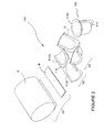
- FIG. 1 there is shown a perspective view of a process for forming a primary package 24, which primary package 24 is intended to contain a product such as a foodstuff or beverage.
- a first stage S1 is to provide a blank B.
- the blank B is cut from a sheet of material 12.
- a second stage S2 the blank B is placed in a mould M1, M101, best illustrated in Figures 3A, 3B, 4A and 4B .
- the material of the blank B is stretched during the moulding process to take the form of the mould M1, M101.
- the mould M1, M101 comprises two portions, each for forming one half of the package 24.
- the blank B is moulded into a part formed package 20 comprising two sections P1, P2.
- Each section P1, P2 provides a side wall 14, 18, one half of each of the opposing end walls 15A, 16A/15B, 16B of the package 24 and one half of the base wall.
- the part formed package 20 comprises a first flange F1.
- the first flange F1 is formed integrally with the side walls 14, 18, end walls 15A, 15B, 16A, 16B and base of the package.
- the first flange F1 extends perpendicularly from an edge of each half of the base wall opposing the connection of the base wall to the respective side wall and first flange F1 extends from edges of each half of the opposing end walls 15A, 15B, 16A, 16B.
- the flange F1 joins or couples the first and second part P1, P2 together.
- Second flange F2 extends perpendicularly from upper or end edges of the opposing end walls 15A, 15B, 16A, 16B and side walls 14, 18.
- the second flange F2 is formed integrally with the part-formed package 20.
- the second flange F2 is optionally integral with, or joined to, the first flange F1 and preferably is disposed perpendicularly thereto.
- flange F1 extends across each half of the base wall by folding the first and second part about a fold line 19 coupling the portions.
- the two sections P1, P2 of the part formed package 20 may be separated.
- Adhesive, glue or sealant G is applied to the first flange F1 of one or both sections P1, P2 of the part formed package 20.
- the two sections P1, P2 are brought into contact with one another such that the flange F1 on the first part P1, is aligned with and secured or sealed to the flange F1 on the second part P2 to form a completed package 24.
- the package 24 comprises a first flange F1 which extends across the base wall and along the length of each of the opposing side walls 16A, 16B.
- Figure 2 illustrates a formation of a second embodiment in which the cup or vessel formed comprises a substantially cylindrical shape in which the base is dome shaped.
- First flange F101 extends along opposing sides of the cylindrical walls and across the base.
- the blank B is cut from a roll of sheet material R prior to formation by thermoforming.
- Figure 3A and 3B illustrate thermoforming the blank B into the part formed package 20, 120.
- Blank B is brought into contact with an upper surface of a mould M1 as indicated by direction arrow D1.
- Figures 3A and 3B illustrate use of negative mould M1.
- Figures 4A and 4B illustrate use of a positive mould M101.
- the preferred package may be formed by stretching the sheet material over the positive mould M101.
- edges of the blank B may be clamped in a clamp C101 whilst the blank is stretched over the mould M101 to facilitate formation of the part formed package 20, 120.
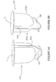
- FIG 5A illustrates a third embodiment of the present invention in which the package 224 comprises a foot or stabiliser 230 in order to allow the package 224 to stand in an upright position.
- the package 224 also comprises a lid L which has been affixed to the second flange.
- the package 224 is constructed using the blank 212 illustrated in Figure 6 .
- the blank 212 comprises a pair of main panels 240, 248 from which the side walls, end walls, base wall, first flange and second flange F201 of the package 224 are constructed.
- the main panels 240, 248 are connected by stabiliser panels 242, 244, 246 which are hingedly connected in a linear series between the main panels 240, 242.
- First stabiliser panel 242 is coupled to main panel 240 by fold line 241 and to second stabiliser panel 244 by fold line 243.
- Second stabiliser panel 244 is coupled to third stabiliser panel 246 by fold line 245.
- Third stabiliser panel 246 is coupled to second main panel 248 by fold line 247.
- first main panel 240 and first stabiliser panel 242 are folded about fold line 243 so as to overlay the second and third stabiliser panels 244, 246 and main panel 248.
- First main panel 240 is then folded back about fold line 241 to overlay first stabiliser panel 242.
- Adhesive is then applied to the first flange F201 shown in Figure 5A of either or both main panels 240, 248.
- the second main panel 248 and third stabiliser panel 246 are then folded about fold line 245.
- the main panels 240, 248 are then folded to be perpendicular to the first, second and third stabiliser panels 242, 244, 246.
- Figure 5B illustrates a package 324 according to a fourth embodiment of the present invention, in which the package 324 comprises a foot or stabiliser 330 in order to allow the package 324 to stand in an upright position.
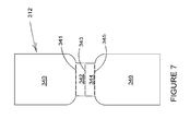
- the package 324 is formed from the blank 312 of Figure 7 ; the blank 312 comprises a pair of main panels 340, 346 interconnected by a pair of strut panels 342, 344.
- the main panels 340, 346 are moulded to form the side, end, base walls, first flange and second flange F301 of the package 324.
- Adhesive is applied to the first flange F301 of one or both of the main panels 340, 346. Adhesive is not applied to a lowermost portion, adjacent the strut panels 342, 344 of each the first flanges F301 of the first and second portions P301, P302 such that these portions may be folded outwardly away from one to form an inverted V shape.
- the folded portions of the first flange F301 form legs upon which the package 324 can rest in an upright position.
- the lowermost portions of each of the first flanges F301 may comprise one or more fold lines, not shown, which define, in part, the legs and facilitate folding the lowermost portions outwardly.
- the strut panels 342, 344 may be folded about fold line 343 to be placed in overlapping relationship with one another and fold lines 341, 345 to be placed in overlapping relationship with, and disposed between, the lowermost portions of each of the first flanges F301 when the legs are not in use.
- Figure 8 illustrates a blank 412 for forming a package according to a fifth embodiment of the present invention
- the blank 412 comprises a pair of main panels 440, 442.
- the main panels 440, 442 are hingedly connected together by fold line 441, which extends along a side edge thereof, by regions which form the part of the first flange which extends along one of the side or end walls of the package.
- a foot panel 444, 446 is attached to each of the main panels 440, 442 along an end edge by a respective fold line 443, 445.
- the side, end and base walls of the package are formed from the main panels 440, 442 by thermoforming, as described above.
- the two halves are secured together by adhering the first flanges of each half of the package together; no adhesive is applied to the foot panels 444, 446.
- the package can be filled with a product and, if desired, a lid can be applied preferably by securing to the second flange.
- FIGS 9A to 9D illustrate a sixth embodiment of the invention in which a foot or stabiliser 556, 558 is thermoformed along with the side, end and base walls of the package 524.
- the package 524 is formed from a blank having main panels for forming each half P501, P502 of the package 524.
- the two halves P501, P502 are coupled together; each of the first flanges F501 are hinged together by a fold line 519.
- the fold line 519 is interrupted by a cut line or weakened line of severance 552.
- a second cut line or weakened line 550, 554 is formed in the first flange F501 of each of the first and second parts P501, P502.
- the packages will be formed from sheet material, preferably paperboard, which can be thermoformed into desired shapes.
- sheet material preferably paperboard
- An example of paperboard useful with the invention is disclosed in US Patent No. 6,024,832 which is hereby incorporated by reference.
- the paperboard may be coated with a moisture resistant barrier or specific gas barrier to seal the package when utilised with foodstuffs or beverages.
- This coating may be formed from plastics material, such as but not limited to polyethylene or polylactic acid.
- An advantage of the invention is that it allows formation of packages having wide variety of shapes.
- thermoformed trays or packages typically have a depth to area ration of up to 0.6, where area refers to the dimension of the area of the top of the open end of the package, and the depth refers to the dimension between the open top and the base.
- the present invention allows formation of packages having depth to area ratios in excess of 0.6, in excess of 1, in excess of 2, and in excess of 2.5, preferably 2.65.
- the present invention can form a cup having a top area of 2375 mm 2 and a depth of 63mm, having a depth to area ratio 2.65, which cup has a capacity of 125cl, whereas known trays or packages with a capacity of 125cl would typically require an area of 48830 mm 2 and a depth of 38 mm, depth to area ratio of 0.08.
- the cup or vessel of the present invention is not formed by stretching a sheet of material from the top of the cup to the bottom of the cup, but rather the cup is formed by stretching the sheet of material or blank one half of a dimension perpendicular to the depth of the cup or package, for example half of the length dimension of the side or end wall.
- hinged connection should not be construed as necessarily referring to a single fold line only; indeed it is envisage that hinged connection can be formed from one or more of the following, a short slit, a frangible line or a fold line without departing from the scope of the invention.
Landscapes
- Engineering & Computer Science (AREA)
- Mechanical Engineering (AREA)
- Ceramic Engineering (AREA)
- Packages (AREA)
Abstract
A cup or vessel for holding a product such as foodstuffs or beverages, the cup or vessel comprising a hollow or tubular structure having at least one closed end there further comprising a first flange extending along opposing sides of the tubular structure and across the closed end.
Description
- The present invention relates to a package and a method of forming the package, more specifically, but not exclusively to a package comprising a sealing flange.
- In the field of packaging, it is often required to provide consumers with a primary package for receiving a product to be delivered to a user.
-
US 6,024,832 discloses a method and apparatus for producing extensible paper and which allows paper to be formed and shaped, wherein the paper can be preformed to a desired profile. - It is desirable to be able to produce packages of a variety of shape and dimensions.
- It is also desirable to minimise or reduce the use of plastics materials and to manufacture the package from sustainable materials.
- In particular, it is desirable to produce packages such as cups for holding beverages or foodstuffs.
- Typically, such packages are produced using plastics, material such as polystyrene, polyethylene, polyethylene terephthalate, polypropylene.
- A sheet of material is formed into a cup by thermoforming, vacuum forming or blow forming, where the sheet of material is heated to a pliable forming temperature and stretched over a mould.
- The shape and/or dimensions of the packages formed by such techniques are limited by the stretchability or plasticity of the material and the dimensions of the sheet being stretched. This can make formation of elongate packages, packages having a substantially tubular shape with a long tubular axis and small cross-section, problematic.
- The present invention seeks to overcome or at least mitigate the problems of the prior art.
- According to a first aspect of the present invention there is provided a cup or vessel for holding a product such as foodstuffs or beverages, the cup or vessel comprising a hollow or tubular structure having at least one closed end there further comprising a first flange extending along opposing sides of the tubular structure and across the closed end.
- Preferably, there further comprises a second flange extending about a second open end of the tubular structure for receiving a lid or cover, which second flange is disposed perpendicular to the first flange.
- Alternatively, the first and/or second flange are disposed inside or outside the cup or vessel.
- Preferably, the cup comprises a foot or stabiliser for allowing the cup to stand upright.
- Preferably, the foot or stabiliser is formed or struck from the flange.
- Preferably, the cup or vessel is formed from two or more component parts secured together to seal the contents therein, preferably adhered together.
- Preferably, the two or more component parts are hingedly connected to one another before being secured together.
- Preferably, the cup or vessel is formed from paperboard.
- Preferably, the cup or vessel further comprises a moisture resistance barrier.
- Preferably, the cup or vessel is formed by thermoforming a sheet material.
- Alternatively, the second flange is coupled to a second flange of one or more similar cups or vessels.
- Optionally, the hollow or tubular structure defines a tubular axis and the first flange is disposed along a plane that is parallel to, or includes, the tubular axis.
- According to a second aspect of the invention there is provided a package comprising a cup or vessel loaded with product and having a lid to seal the contents therein.
- According to a third aspect of the present invention there is provided a method of forming a package comprising providing a sheet of material; thermoforming said sheet to form a first portion and a second portion of a container, each portion comprising a bottom, a pair of opposed sides, and one end extending between the sides and a flange extending thereabout, securing the first portion and second portions together to form a tubular structure having a closed end by securing the flanges of the first and second part to one another.
- Preferably, the method of forming a package further comprises filling the package with a product.
- Preferably, the method of forming a package further comprises applying a lid to the package.
- Preferably, the method of forming a package further comprises constructing a foot or stabiliser upon which the package may stand upright.
- Preferably, said first and second portions are hingedly connected to one another by a fold line, and the method comprises folding the first and/or second part about the fold line to bring the flanges together.
- According to a fourth aspect of the present invention there is provided a method for forming a package, said package comprising a hollow structure closed at one end, having a depth defined between the closed end and an open end, and width defined between side walls of the hollow structure; the method comprising providing a sheet of material, providing a mould comprising a first part defining a first part of the side walls of the hollow structure and a first part of the closed end; and a second part defining a second part of the side walls of the hollow structure and a second part of the closed end stretching the sheet of material about the mould to form a first and second part of the package; securing the first and second parts of the package together to complete the package.
- Exemplary embodiments of the invention will now be described with reference to the accompanying drawings, in which:
- FIGURE 1
- illustrates schematically formation of a package according to a first embodiment;
- FIGURE 2
- illustrates schematically formation of package according to a second embodiment;
- FIGURE 3A
- illustrates schematically an apparatus in a first stage of thermoforming a package;
- FIGURE 3B
- illustrates schematically the apparatus in a second stage of thermoforming a package;
- FIGURE 4A
- illustrates schematically an alternative apparatus in a first stage of thermoforming a package;
- FIGURES 4B
- illustrates schematically the alternative apparatus in a second stage of thermoforming a package;
- FIGURE 5A
- illustrates a perspective view of a package; according to a third embodiment;
- FIGURE 5B
- illustrates a perspective view of a package according to a fourth embodiment;
- FIGURE 6
- illustrates a plan view of a blank for forming the package of
Figures 5A ; - FIGURE 7
- illustrates a plan view of a blank for forming a package of
Figure 5B ; - FIGURE 8
- illustrates a plan view of a blank for forming a package according to a fifth embodiment;
- FIGURE 9A
- illustrates a perspective view of a part formed package of a sixth embodiment;
- FIGURE 9B
- illustrates a perspective view of a part formed package of
Figure 9A ; - FIGURE 9C
- illustrates a perspective view of a package according to the sixth embodiment; and
- FIGURE 9D
- illustrates a side view of a package according to the sixth embodiment.
- Detailed descriptions of specific embodiments of the packages, blanks and cartons are disclosed herein. It will be understood that the disclosed embodiments are merely examples of the way in which certain aspects of the invention can be implemented and do not represent an exhaustive list of all of the ways the invention may be embodied. Indeed, it will be understood that the packages, blanks and cartons described herein may be embodied in various and alternative forms. The Figures are not necessarily to scale and some features may be exaggerated or minimised to show details of particular component. Well-known components, material or methods are not necessarily described in great detail in order to avoid obscuring the present disclosure. Any specific structural and functional details disclosed herein are not to be interpreted as limiting but merely as a basis for the claims and as a representative basis for teaching one skilled in the art to variously employ the invention.
- Referring to
Figure 1 there is shown a perspective view of a process for forming aprimary package 24, whichprimary package 24 is intended to contain a product such as a foodstuff or beverage. - A first stage S1 is to provide a blank B. The blank B is cut from a sheet of
material 12. In a second stage S2 the blank B is placed in a mould M1, M101, best illustrated inFigures 3A, 3B, 4A and 4B . The material of the blank B is stretched during the moulding process to take the form of the mould M1, M101. - In the preferred embodiment the mould M1, M101 comprises two portions, each for forming one half of the
package 24. The blank B is moulded into a part formedpackage 20 comprising two sections P1, P2. Each section P1, P2 provides aside wall end walls package 24 and one half of the base wall. - The part formed
package 20 comprises a first flange F1. The first flange F1 is formed integrally with theside walls end walls - The first flange F1 extends perpendicularly from an edge of each half of the base wall opposing the connection of the base wall to the respective side wall and first flange F1 extends from edges of each half of the opposing
end walls - An optional second flange F2 may be provided. Second flange F2 extends perpendicularly from upper or end edges of the opposing
end walls side walls - Preferably the second flange F2 is formed integrally with the part-formed
package 20. The second flange F2 is optionally integral with, or joined to, the first flange F1 and preferably is disposed perpendicularly thereto. - In a third stage S3 of the package formation, the first and second part P1, P2 are brought together, flange F1 extends across each half of the base wall by folding the first and second part about a
fold line 19 coupling the portions. - In alternative embodiments the two sections P1, P2 of the part formed
package 20 may be separated. - Adhesive, glue or sealant G is applied to the first flange F1 of one or both sections P1, P2 of the part formed
package 20. The two sections P1, P2 are brought into contact with one another such that the flange F1 on the first part P1, is aligned with and secured or sealed to the flange F1 on the second part P2 to form a completedpackage 24. - The
package 24 comprises a first flange F1 which extends across the base wall and along the length of each of the opposingside walls - Referring now to
Figures 2 ,5A to 9D there is shown alternative embodiments of the present invention. In the second and third illustrated embodiment, like numerals have, where possible, been used to denote like parts, albeit with the addition of the prefix "100" or "200" and so on to indicate that these features belong to the second embodiment. The alternative embodiments share many common features with the first embodiment and therefore only the differences from the embodiment illustrated inFigure 1 will be described in any greater detail. -
Figure 2 illustrates a formation of a second embodiment in which the cup or vessel formed comprises a substantially cylindrical shape in which the base is dome shaped. First flange F101 extends along opposing sides of the cylindrical walls and across the base. - The blank B is cut from a roll of sheet material R prior to formation by thermoforming.
-
Figure 3A and 3B illustrate thermoforming the blank B into the part formedpackage 20, 120. Blank B is brought into contact with an upper surface of a mould M1 as indicated by direction arrow D1.Figures 3A and 3B illustrate use of negative mould M1. - The blank B is then forced into the shape of the mould M1; this may be achieved by pressing the blank B into the mould M1 with a punch (not shown). Alternatively, the blank B may be clamped in position using a clamp C1, see
Figure 3B . The blank B may be forced into the shape of the mould M1 either by blowing P the sheet into the mould M1 or alternatively by using a vacuum pump which communicates with the space between the mould M1 and the blank B and the pump viaconduits 50. -
Figures 4A and 4B illustrate use of a positive mould M101. The preferred package may be formed by stretching the sheet material over the positive mould M101. - The edges of the blank B may be clamped in a clamp C101 whilst the blank is stretched over the mould M101 to facilitate formation of the part formed
package 20, 120. -
Figure 5A illustrates a third embodiment of the present invention in which thepackage 224 comprises a foot orstabiliser 230 in order to allow thepackage 224 to stand in an upright position. Thepackage 224 also comprises a lid L which has been affixed to the second flange. Thepackage 224 is constructed using the blank 212 illustrated inFigure 6 . The blank 212 comprises a pair ofmain panels package 224 are constructed. Themain panels stabiliser panels main panels First stabiliser panel 242 is coupled tomain panel 240 byfold line 241 and tosecond stabiliser panel 244 byfold line 243.Second stabiliser panel 244 is coupled tothird stabiliser panel 246 byfold line 245.Third stabiliser panel 246 is coupled to secondmain panel 248 byfold line 247. - Once the
main panels package 224, the firstmain panel 240 andfirst stabiliser panel 242 are folded aboutfold line 243 so as to overlay the second andthird stabiliser panels main panel 248. Firstmain panel 240 is then folded back aboutfold line 241 to overlayfirst stabiliser panel 242. Adhesive is then applied to the first flange F201 shown inFigure 5A of either or bothmain panels main panel 248 andthird stabiliser panel 246 are then folded aboutfold line 245. Themain panels third stabiliser panels -
Figure 5B illustrates apackage 324 according to a fourth embodiment of the present invention, in which thepackage 324 comprises a foot orstabiliser 330 in order to allow thepackage 324 to stand in an upright position. Thepackage 324 is formed from the blank 312 ofFigure 7 ; the blank 312 comprises a pair ofmain panels strut panels main panels package 324. - Adhesive is applied to the first flange F301 of one or both of the
main panels strut panels package 324 can rest in an upright position. The lowermost portions of each of the first flanges F301 may comprise one or more fold lines, not shown, which define, in part, the legs and facilitate folding the lowermost portions outwardly. - The
strut panels fold line 343 to be placed in overlapping relationship with one another and foldlines -
Figure 8 illustrates a blank 412 for forming a package according to a fifth embodiment of the present invention; the blank 412 comprises a pair ofmain panels main panels fold line 441, which extends along a side edge thereof, by regions which form the part of the first flange which extends along one of the side or end walls of the package. - A
foot panel main panels respective fold line - The side, end and base walls of the package are formed from the
main panels - Once the side, end and base walls of the package have been formed, the two halves are secured together by adhering the first flanges of each half of the package together; no adhesive is applied to the
foot panels - The package can be filled with a product and, if desired, a lid can be applied preferably by securing to the second flange.
- When it is desired, for example when an end user wishes to consume the product, the
foot panels foot panels -
Figures 9A to 9D illustrate a sixth embodiment of the invention in which a foot orstabiliser package 524. Thepackage 524 is formed from a blank having main panels for forming each half P501, P502 of thepackage 524. The two halves P501, P502 are coupled together; each of the first flanges F501 are hinged together by afold line 519. Thefold line 519 is interrupted by a cut line or weakened line ofseverance 552. A second cut line or weakenedline second cut lines first cutline 552 and define therebetweenfoot forming regions foot forming regions package 521 can then be folded aboutfold line 519 and secured together. In this embodiment thefoot forming regions foot forming regions cut line 552. - It is envisaged that the packages will be formed from sheet material, preferably paperboard, which can be thermoformed into desired shapes. An example of paperboard useful with the invention is disclosed in
US Patent No. 6,024,832 which is hereby incorporated by reference. - It is also envisaged that the paperboard may be coated with a moisture resistant barrier or specific gas barrier to seal the package when utilised with foodstuffs or beverages. This coating may be formed from plastics material, such as but not limited to polyethylene or polylactic acid.
- It is envisaged that the package will comprise a lid to seal the contents within the package. The lid may be formed from coated paperboard, aluminium or plastic.
- An advantage of the invention is that it allows formation of packages having wide variety of shapes.
- Known thermoformed trays or packages typically have a depth to area ration of up to 0.6, where area refers to the dimension of the area of the top of the open end of the package, and the depth refers to the dimension between the open top and the base. The present invention allows formation of packages having depth to area ratios in excess of 0.6, in excess of 1, in excess of 2, and in excess of 2.5, preferably 2.65.
- For example the present invention can form a cup having a top area of 2375 mm2 and a depth of 63mm, having a depth to area ratio 2.65, which cup has a capacity of 125cl, whereas known trays or packages with a capacity of 125cl would typically require an area of 48830 mm2 and a depth of 38 mm, depth to area ratio of 0.08.
- It will be appreciated that, unlike known techniques, the cup or vessel of the present invention is not formed by stretching a sheet of material from the top of the cup to the bottom of the cup, but rather the cup is formed by stretching the sheet of material or blank one half of a dimension perpendicular to the depth of the cup or package, for example half of the length dimension of the side or end wall.
- It can be appreciated that various changes may be made within the scope of the present invention, for example, the size and shape of the panels and apertures may be adjusted to form articles of differing size or shape.
- It will be recognised that as used herein, directional references such as "top", "bottom", "front", "back", "end", "side", "inner", "outer", "upper" and "lower" do not limit the respective panels to such orientation, but merely serve to distinguish these panels from one another. Any reference to hinged connection should not be construed as necessarily referring to a single fold line only; indeed it is envisage that hinged connection can be formed from one or more of the following, a short slit, a frangible line or a fold line without departing from the scope of the invention.
Claims (19)
- A cup or vessel for holding a product such as foodstuffs or beverages, the cup or vessel comprising a hollow or tubular structure having at least one closed end there further comprising a first flange extending along opposing sides of the tubular structure and across the closed end.
- The cup or vessel according to either of claims 1 or 2, wherein there further comprises a second flange extending about a second open end of the tubular structure for receiving a lid or cover, which second flange is disposed perpendicular to the first flange.
- The cup or vessel according to claim 1 wherein the first and/or second flange are disposed inside or outside the cup or vessel.
- The cup or vessel according to any of claims 1 to 4 wherein the cup comprises a foot or stabiliser for allowing the cup to stand upright.
- The cup or vessel according to claim 4, wherein the foot or stabiliser is formed or struck from the flange.
- The cup or vessel according to any of claims 1 to 5, wherein the cup or vessel is formed from two or more component parts secured together to seal the contents therein, preferably adhered together.
- The cup or vessel according to claim 6, wherein the two or more component parts are hingedly connected to one another before being secured together.
- The cup or vessel according to any of claims 1 to 7, wherein the cup or vessel is formed from paperboard.
- The cup or vessel according to any of claims 1 to 8, further comprising a moisture resistance barrier.
- The cup or vessel according to any of claims 1 to 9, formed by thermo forming a sheet material.
- The cup or vessel according to claim 2 wherein the second flange is coupled to a second flange of one or more similar cups or vessels.
- The cup or vessel according to claim 1 or 2, wherein the hollow or tubular structure defines a tubular axis, and wherein the first flange is disposed along a plane that is parallel to, or includes, the tubular axis.
- A package comprising a cup or vessel according to any preceding claim, loaded with product and having a lid to seal the contents therein.
- A method of forming a package comprising
providing a sheet of material;
thermoforming said sheet to form a first portion and a second portion of a container, each portion comprising a bottom, a pair of opposed sides, and one end extending between the sides and a flange extending thereabout;
securing the first portion and second portions together to form a tubular structure having a closed end by securing the flanges of the first and second part to one another. - A method of forming a package according to claim 14 further comprising filling the package with a product.
- A method of forming a package according to claims 14 or 15 further comprising applying a lid to the package.
- A method of forming a package according to any of claims 14 to 16 further comprising constructing a foot or stabiliser upon which the package may stand upright.
- A method of forming a package according to any of clams 14 to 17 wherein said first and second portions are hingedly connected to one another by a fold line and the method comprises folding the first and/or second part about the fold line to bring the flanges together.
- A method for forming a package, said package comprising a hollow structure closed at one end, having a depth defined between the closed end and an open end, and width defined between side walls of the hollow structure;
the method comprising;
providing a sheet of material;
providing a mould comprising
a first part defining a first part of the side walls of the hollow structure and a first part of the closed end; and
a second part defining a second part of the side walls of the hollow structure and a second part of the closed end;
stretching the sheet of material about the mould to form a first and second part of the package;
securing the first and second parts of the package together to complete the package.
Applications Claiming Priority (1)
| Application Number | Priority Date | Filing Date | Title |
|---|---|---|---|
| GBGB1104828.7A GB201104828D0 (en) | 2011-03-22 | 2011-03-22 | Package and method of forming the same |
Publications (1)
| Publication Number | Publication Date |
|---|---|
| EP2502835A1 true EP2502835A1 (en) | 2012-09-26 |
Family
ID=44012980
Family Applications (1)
| Application Number | Title | Priority Date | Filing Date |
|---|---|---|---|
| EP12160673A Withdrawn EP2502835A1 (en) | 2011-03-22 | 2012-03-22 | Package and method of forming the same |
Country Status (2)
| Country | Link |
|---|---|
| EP (1) | EP2502835A1 (en) |
| GB (1) | GB201104828D0 (en) |
Citations (6)
| Publication number | Priority date | Publication date | Assignee | Title |
|---|---|---|---|---|
| FR1046215A (en) * | 1951-12-07 | 1953-12-04 | Packaging improvements for pourable products | |
| US3366290A (en) * | 1966-09-08 | 1968-01-30 | Mojonnier Inc | Plastic container with integral handle |
| US3380608A (en) * | 1966-06-14 | 1968-04-30 | American Can Co | Molded integral cap and container |
| DE3643030A1 (en) * | 1986-12-17 | 1988-06-30 | Unionpack Ind Lohnverpackungs | METHOD FOR PRODUCING A FILM CONTAINER, FILM CONTAINER PRODUCED BY THE PROCESS AND THERMOFORMING FORM FOR IMPLEMENTING THE PROCESS |
| US6024832A (en) | 1995-04-07 | 2000-02-15 | Giorgio Trani Cartiere Cariolaro S. P. A. | Method and apparatus for producing extensible paper |
| US20100155396A1 (en) * | 2008-12-19 | 2010-06-24 | Warner Jim F | Environmentally friendly liquid container and method of manufacture |
-
2011
- 2011-03-22 GB GBGB1104828.7A patent/GB201104828D0/en not_active Ceased
-
2012
- 2012-03-22 EP EP12160673A patent/EP2502835A1/en not_active Withdrawn
Patent Citations (6)
| Publication number | Priority date | Publication date | Assignee | Title |
|---|---|---|---|---|
| FR1046215A (en) * | 1951-12-07 | 1953-12-04 | Packaging improvements for pourable products | |
| US3380608A (en) * | 1966-06-14 | 1968-04-30 | American Can Co | Molded integral cap and container |
| US3366290A (en) * | 1966-09-08 | 1968-01-30 | Mojonnier Inc | Plastic container with integral handle |
| DE3643030A1 (en) * | 1986-12-17 | 1988-06-30 | Unionpack Ind Lohnverpackungs | METHOD FOR PRODUCING A FILM CONTAINER, FILM CONTAINER PRODUCED BY THE PROCESS AND THERMOFORMING FORM FOR IMPLEMENTING THE PROCESS |
| US6024832A (en) | 1995-04-07 | 2000-02-15 | Giorgio Trani Cartiere Cariolaro S. P. A. | Method and apparatus for producing extensible paper |
| US20100155396A1 (en) * | 2008-12-19 | 2010-06-24 | Warner Jim F | Environmentally friendly liquid container and method of manufacture |
Also Published As
| Publication number | Publication date |
|---|---|
| GB201104828D0 (en) | 2011-05-04 |
Similar Documents
| Publication | Publication Date | Title |
|---|---|---|
| US9463896B2 (en) | Carton with opening feature | |
| JP7109373B2 (en) | Packaging sleeves, wrappers, and methods of making wrappers | |
| EP2650223A1 (en) | Production method for packaging container, and packaging container | |
| US9725204B2 (en) | Paper-based cylindrical bottle | |
| JP5748643B2 (en) | Packaging container manufacturing method and packaging container | |
| KR20180028909A (en) | Paper cup, a blank for a paper cup, and use of a paper cup | |
| JPWO2002010020A1 (en) | Manufacturing method of paper packaging container and paper packaging container | |
| MXPA01011015A (en) | Non-round composite container with inverse curvature. | |
| US10407210B2 (en) | Plastic cup with a thin outer sleeve and food product pack comprising such cups | |
| TW201206780A (en) | Sealed package for pourable food products and packaging material for producing sealed packages for pourable food products | |
| JP2019510698A (en) | Packaging sleeves, packaging laminates, and packaging sleeve blanks for composite packaging | |
| RU2671902C2 (en) | Packaging material blank, package with such device and a method for manufacturing an opening device | |
| EP2650222A1 (en) | Production method for packaging container and packaging container | |
| EP3371072B1 (en) | Package or product and a package or product roll | |
| JP2015145260A (en) | Packaging container manufacturing method and packaging container | |
| EP2474479A1 (en) | Cardboard container for aseptic liquids | |
| US20210094723A1 (en) | A package | |
| KR101377072B1 (en) | Foldable container and method of manufacturing it | |
| WO2014010612A1 (en) | Manufacturing method for packaging container and packaging container | |
| WO2014010613A1 (en) | Manufacturing method for packaging container and packaging container | |
| KR101227778B1 (en) | Collapsible container for instant noodle(ramen) | |
| EP3530587B1 (en) | Container for pourable food products | |
| WO2005061215A1 (en) | Container blank and method of producing containers from these | |
| JP2012121577A (en) | Method for manufacturing packaging container and packaging container | |
| WO2015199158A1 (en) | Pouch sleeve |
Legal Events
| Date | Code | Title | Description |
|---|---|---|---|
| PUAI | Public reference made under article 153(3) epc to a published international application that has entered the european phase |
Free format text: ORIGINAL CODE: 0009012 |
|
| 17P | Request for examination filed |
Effective date: 20120322 |
|
| AK | Designated contracting states |
Kind code of ref document: A1 Designated state(s): AL AT BE BG CH CY CZ DE DK EE ES FI FR GB GR HR HU IE IS IT LI LT LU LV MC MK MT NL NO PL PT RO RS SE SI SK SM TR |
|
| AX | Request for extension of the european patent |
Extension state: BA ME |
|
| STAA | Information on the status of an ep patent application or granted ep patent |
Free format text: STATUS: THE APPLICATION IS DEEMED TO BE WITHDRAWN |
|
| 18D | Application deemed to be withdrawn |
Effective date: 20130327 |