EP2502829B1 - Demisable fuel supply system - Google Patents
Demisable fuel supply system Download PDFInfo
- Publication number
- EP2502829B1 EP2502829B1 EP12160308.8A EP12160308A EP2502829B1 EP 2502829 B1 EP2502829 B1 EP 2502829B1 EP 12160308 A EP12160308 A EP 12160308A EP 2502829 B1 EP2502829 B1 EP 2502829B1
- Authority
- EP
- European Patent Office
- Prior art keywords
- storage tank
- supply system
- fuel supply
- propellant
- based coating
- Prior art date
- Legal status (The legal status is an assumption and is not a legal conclusion. Google has not performed a legal analysis and makes no representation as to the accuracy of the status listed.)
- Not-in-force
Links
Images

Classifications
-
- B—PERFORMING OPERATIONS; TRANSPORTING
- B64—AIRCRAFT; AVIATION; COSMONAUTICS
- B64G—COSMONAUTICS; VEHICLES OR EQUIPMENT THEREFOR
- B64G1/00—Cosmonautic vehicles
- B64G1/22—Parts of, or equipment specially adapted for fitting in or to, cosmonautic vehicles
- B64G1/40—Arrangements or adaptations of propulsion systems
- B64G1/402—Propellant tanks; Feeding propellants
-
- F—MECHANICAL ENGINEERING; LIGHTING; HEATING; WEAPONS; BLASTING
- F02—COMBUSTION ENGINES; HOT-GAS OR COMBUSTION-PRODUCT ENGINE PLANTS
- F02K—JET-PROPULSION PLANTS
- F02K9/00—Rocket-engine plants, i.e. plants carrying both fuel and oxidant therefor; Control thereof
- F02K9/42—Rocket-engine plants, i.e. plants carrying both fuel and oxidant therefor; Control thereof using liquid or gaseous propellants
- F02K9/60—Constructional parts; Details not otherwise provided for
- F02K9/605—Reservoirs
-
- F—MECHANICAL ENGINEERING; LIGHTING; HEATING; WEAPONS; BLASTING
- F17—STORING OR DISTRIBUTING GASES OR LIQUIDS
- F17C—VESSELS FOR CONTAINING OR STORING COMPRESSED, LIQUEFIED OR SOLIDIFIED GASES; FIXED-CAPACITY GAS-HOLDERS; FILLING VESSELS WITH, OR DISCHARGING FROM VESSELS, COMPRESSED, LIQUEFIED, OR SOLIDIFIED GASES
- F17C13/00—Details of vessels or of the filling or discharging of vessels
- F17C13/008—Details of vessels or of the filling or discharging of vessels for use under microgravity conditions
-
- B—PERFORMING OPERATIONS; TRANSPORTING
- B64—AIRCRAFT; AVIATION; COSMONAUTICS
- B64G—COSMONAUTICS; VEHICLES OR EQUIPMENT THEREFOR
- B64G1/00—Cosmonautic vehicles
- B64G1/22—Parts of, or equipment specially adapted for fitting in or to, cosmonautic vehicles
- B64G1/40—Arrangements or adaptations of propulsion systems
- B64G1/402—Propellant tanks; Feeding propellants
- B64G1/4021—Tank construction; Details thereof
-
- F—MECHANICAL ENGINEERING; LIGHTING; HEATING; WEAPONS; BLASTING
- F05—INDEXING SCHEMES RELATING TO ENGINES OR PUMPS IN VARIOUS SUBCLASSES OF CLASSES F01-F04
- F05D—INDEXING SCHEME FOR ASPECTS RELATING TO NON-POSITIVE-DISPLACEMENT MACHINES OR ENGINES, GAS-TURBINES OR JET-PROPULSION PLANTS
- F05D2230/00—Manufacture
- F05D2230/90—Coating; Surface treatment
-
- F—MECHANICAL ENGINEERING; LIGHTING; HEATING; WEAPONS; BLASTING
- F05—INDEXING SCHEMES RELATING TO ENGINES OR PUMPS IN VARIOUS SUBCLASSES OF CLASSES F01-F04
- F05D—INDEXING SCHEME FOR ASPECTS RELATING TO NON-POSITIVE-DISPLACEMENT MACHINES OR ENGINES, GAS-TURBINES OR JET-PROPULSION PLANTS
- F05D2300/00—Materials; Properties thereof
- F05D2300/10—Metals, alloys or intermetallic compounds
- F05D2300/13—Refractory metals, i.e. Ti, V, Cr, Zr, Nb, Mo, Hf, Ta, W
- F05D2300/133—Titanium
-
- F—MECHANICAL ENGINEERING; LIGHTING; HEATING; WEAPONS; BLASTING
- F05—INDEXING SCHEMES RELATING TO ENGINES OR PUMPS IN VARIOUS SUBCLASSES OF CLASSES F01-F04
- F05D—INDEXING SCHEME FOR ASPECTS RELATING TO NON-POSITIVE-DISPLACEMENT MACHINES OR ENGINES, GAS-TURBINES OR JET-PROPULSION PLANTS
- F05D2300/00—Materials; Properties thereof
- F05D2300/50—Intrinsic material properties or characteristics
- F05D2300/51—Hydrophilic, i.e. being or having wettable properties
-
- F—MECHANICAL ENGINEERING; LIGHTING; HEATING; WEAPONS; BLASTING
- F17—STORING OR DISTRIBUTING GASES OR LIQUIDS
- F17C—VESSELS FOR CONTAINING OR STORING COMPRESSED, LIQUEFIED OR SOLIDIFIED GASES; FIXED-CAPACITY GAS-HOLDERS; FILLING VESSELS WITH, OR DISCHARGING FROM VESSELS, COMPRESSED, LIQUEFIED, OR SOLIDIFIED GASES
- F17C2201/00—Vessel construction, in particular geometry, arrangement or size
- F17C2201/01—Shape
- F17C2201/0128—Shape spherical or elliptical
-
- F—MECHANICAL ENGINEERING; LIGHTING; HEATING; WEAPONS; BLASTING
- F17—STORING OR DISTRIBUTING GASES OR LIQUIDS
- F17C—VESSELS FOR CONTAINING OR STORING COMPRESSED, LIQUEFIED OR SOLIDIFIED GASES; FIXED-CAPACITY GAS-HOLDERS; FILLING VESSELS WITH, OR DISCHARGING FROM VESSELS, COMPRESSED, LIQUEFIED, OR SOLIDIFIED GASES
- F17C2201/00—Vessel construction, in particular geometry, arrangement or size
- F17C2201/05—Size
- F17C2201/054—Size medium (>1 m3)
-
- F—MECHANICAL ENGINEERING; LIGHTING; HEATING; WEAPONS; BLASTING
- F17—STORING OR DISTRIBUTING GASES OR LIQUIDS
- F17C—VESSELS FOR CONTAINING OR STORING COMPRESSED, LIQUEFIED OR SOLIDIFIED GASES; FIXED-CAPACITY GAS-HOLDERS; FILLING VESSELS WITH, OR DISCHARGING FROM VESSELS, COMPRESSED, LIQUEFIED, OR SOLIDIFIED GASES
- F17C2201/00—Vessel construction, in particular geometry, arrangement or size
- F17C2201/05—Size
- F17C2201/056—Small (<1 m3)
-
- F—MECHANICAL ENGINEERING; LIGHTING; HEATING; WEAPONS; BLASTING
- F17—STORING OR DISTRIBUTING GASES OR LIQUIDS
- F17C—VESSELS FOR CONTAINING OR STORING COMPRESSED, LIQUEFIED OR SOLIDIFIED GASES; FIXED-CAPACITY GAS-HOLDERS; FILLING VESSELS WITH, OR DISCHARGING FROM VESSELS, COMPRESSED, LIQUEFIED, OR SOLIDIFIED GASES
- F17C2203/00—Vessel construction, in particular walls or details thereof
- F17C2203/06—Materials for walls or layers thereof; Properties or structures of walls or their materials
- F17C2203/0602—Wall structures; Special features thereof
- F17C2203/0607—Coatings
-
- F—MECHANICAL ENGINEERING; LIGHTING; HEATING; WEAPONS; BLASTING
- F17—STORING OR DISTRIBUTING GASES OR LIQUIDS
- F17C—VESSELS FOR CONTAINING OR STORING COMPRESSED, LIQUEFIED OR SOLIDIFIED GASES; FIXED-CAPACITY GAS-HOLDERS; FILLING VESSELS WITH, OR DISCHARGING FROM VESSELS, COMPRESSED, LIQUEFIED, OR SOLIDIFIED GASES
- F17C2203/00—Vessel construction, in particular walls or details thereof
- F17C2203/06—Materials for walls or layers thereof; Properties or structures of walls or their materials
- F17C2203/0634—Materials for walls or layers thereof
- F17C2203/0636—Metals
- F17C2203/0646—Aluminium
-
- F—MECHANICAL ENGINEERING; LIGHTING; HEATING; WEAPONS; BLASTING
- F17—STORING OR DISTRIBUTING GASES OR LIQUIDS
- F17C—VESSELS FOR CONTAINING OR STORING COMPRESSED, LIQUEFIED OR SOLIDIFIED GASES; FIXED-CAPACITY GAS-HOLDERS; FILLING VESSELS WITH, OR DISCHARGING FROM VESSELS, COMPRESSED, LIQUEFIED, OR SOLIDIFIED GASES
- F17C2203/00—Vessel construction, in particular walls or details thereof
- F17C2203/06—Materials for walls or layers thereof; Properties or structures of walls or their materials
- F17C2203/0634—Materials for walls or layers thereof
- F17C2203/0636—Metals
- F17C2203/0648—Alloys or compositions of metals
-
- F—MECHANICAL ENGINEERING; LIGHTING; HEATING; WEAPONS; BLASTING
- F17—STORING OR DISTRIBUTING GASES OR LIQUIDS
- F17C—VESSELS FOR CONTAINING OR STORING COMPRESSED, LIQUEFIED OR SOLIDIFIED GASES; FIXED-CAPACITY GAS-HOLDERS; FILLING VESSELS WITH, OR DISCHARGING FROM VESSELS, COMPRESSED, LIQUEFIED, OR SOLIDIFIED GASES
- F17C2203/00—Vessel construction, in particular walls or details thereof
- F17C2203/06—Materials for walls or layers thereof; Properties or structures of walls or their materials
- F17C2203/0634—Materials for walls or layers thereof
- F17C2203/0658—Synthetics
- F17C2203/0663—Synthetics in form of fibers or filaments
-
- F—MECHANICAL ENGINEERING; LIGHTING; HEATING; WEAPONS; BLASTING
- F17—STORING OR DISTRIBUTING GASES OR LIQUIDS
- F17C—VESSELS FOR CONTAINING OR STORING COMPRESSED, LIQUEFIED OR SOLIDIFIED GASES; FIXED-CAPACITY GAS-HOLDERS; FILLING VESSELS WITH, OR DISCHARGING FROM VESSELS, COMPRESSED, LIQUEFIED, OR SOLIDIFIED GASES
- F17C2209/00—Vessel construction, in particular methods of manufacturing
- F17C2209/22—Assembling processes
- F17C2209/221—Welding
-
- F—MECHANICAL ENGINEERING; LIGHTING; HEATING; WEAPONS; BLASTING
- F17—STORING OR DISTRIBUTING GASES OR LIQUIDS
- F17C—VESSELS FOR CONTAINING OR STORING COMPRESSED, LIQUEFIED OR SOLIDIFIED GASES; FIXED-CAPACITY GAS-HOLDERS; FILLING VESSELS WITH, OR DISCHARGING FROM VESSELS, COMPRESSED, LIQUEFIED, OR SOLIDIFIED GASES
- F17C2209/00—Vessel construction, in particular methods of manufacturing
- F17C2209/22—Assembling processes
- F17C2209/228—Assembling processes by screws, bolts or rivets
-
- F—MECHANICAL ENGINEERING; LIGHTING; HEATING; WEAPONS; BLASTING
- F17—STORING OR DISTRIBUTING GASES OR LIQUIDS
- F17C—VESSELS FOR CONTAINING OR STORING COMPRESSED, LIQUEFIED OR SOLIDIFIED GASES; FIXED-CAPACITY GAS-HOLDERS; FILLING VESSELS WITH, OR DISCHARGING FROM VESSELS, COMPRESSED, LIQUEFIED, OR SOLIDIFIED GASES
- F17C2221/00—Handled fluid, in particular type of fluid
- F17C2221/08—Ergols, e.g. hydrazine
-
- F—MECHANICAL ENGINEERING; LIGHTING; HEATING; WEAPONS; BLASTING
- F17—STORING OR DISTRIBUTING GASES OR LIQUIDS
- F17C—VESSELS FOR CONTAINING OR STORING COMPRESSED, LIQUEFIED OR SOLIDIFIED GASES; FIXED-CAPACITY GAS-HOLDERS; FILLING VESSELS WITH, OR DISCHARGING FROM VESSELS, COMPRESSED, LIQUEFIED, OR SOLIDIFIED GASES
- F17C2270/00—Applications
- F17C2270/01—Applications for fluid transport or storage
- F17C2270/0186—Applications for fluid transport or storage in the air or in space
- F17C2270/0194—Applications for fluid transport or storage in the air or in space for use under microgravity conditions, e.g. space
-
- Y—GENERAL TAGGING OF NEW TECHNOLOGICAL DEVELOPMENTS; GENERAL TAGGING OF CROSS-SECTIONAL TECHNOLOGIES SPANNING OVER SEVERAL SECTIONS OF THE IPC; TECHNICAL SUBJECTS COVERED BY FORMER USPC CROSS-REFERENCE ART COLLECTIONS [XRACs] AND DIGESTS
- Y10—TECHNICAL SUBJECTS COVERED BY FORMER USPC
- Y10T—TECHNICAL SUBJECTS COVERED BY FORMER US CLASSIFICATION
- Y10T137/00—Fluid handling
- Y10T137/2931—Diverse fluid containing pressure systems
-
- Y—GENERAL TAGGING OF NEW TECHNOLOGICAL DEVELOPMENTS; GENERAL TAGGING OF CROSS-SECTIONAL TECHNOLOGIES SPANNING OVER SEVERAL SECTIONS OF THE IPC; TECHNICAL SUBJECTS COVERED BY FORMER USPC CROSS-REFERENCE ART COLLECTIONS [XRACs] AND DIGESTS
- Y10—TECHNICAL SUBJECTS COVERED BY FORMER USPC
- Y10T—TECHNICAL SUBJECTS COVERED BY FORMER US CLASSIFICATION
- Y10T137/00—Fluid handling
- Y10T137/2931—Diverse fluid containing pressure systems
- Y10T137/3115—Gas pressure storage over or displacement of liquid
- Y10T137/3127—With gas maintenance or application
-
- Y—GENERAL TAGGING OF NEW TECHNOLOGICAL DEVELOPMENTS; GENERAL TAGGING OF CROSS-SECTIONAL TECHNOLOGIES SPANNING OVER SEVERAL SECTIONS OF THE IPC; TECHNICAL SUBJECTS COVERED BY FORMER USPC CROSS-REFERENCE ART COLLECTIONS [XRACs] AND DIGESTS
- Y10—TECHNICAL SUBJECTS COVERED BY FORMER USPC
- Y10T—TECHNICAL SUBJECTS COVERED BY FORMER US CLASSIFICATION
- Y10T137/00—Fluid handling
- Y10T137/8593—Systems
- Y10T137/86187—Plural tanks or compartments connected for serial flow
- Y10T137/86212—Plural compartments formed by baffles
-
- Y—GENERAL TAGGING OF NEW TECHNOLOGICAL DEVELOPMENTS; GENERAL TAGGING OF CROSS-SECTIONAL TECHNOLOGIES SPANNING OVER SEVERAL SECTIONS OF THE IPC; TECHNICAL SUBJECTS COVERED BY FORMER USPC CROSS-REFERENCE ART COLLECTIONS [XRACs] AND DIGESTS
- Y10—TECHNICAL SUBJECTS COVERED BY FORMER USPC
- Y10T—TECHNICAL SUBJECTS COVERED BY FORMER US CLASSIFICATION
- Y10T137/00—Fluid handling
- Y10T137/8593—Systems
- Y10T137/86348—Tank with internally extending flow guide, pipe or conduit
-
- Y—GENERAL TAGGING OF NEW TECHNOLOGICAL DEVELOPMENTS; GENERAL TAGGING OF CROSS-SECTIONAL TECHNOLOGIES SPANNING OVER SEVERAL SECTIONS OF THE IPC; TECHNICAL SUBJECTS COVERED BY FORMER USPC CROSS-REFERENCE ART COLLECTIONS [XRACs] AND DIGESTS
- Y10—TECHNICAL SUBJECTS COVERED BY FORMER USPC
- Y10T—TECHNICAL SUBJECTS COVERED BY FORMER US CLASSIFICATION
- Y10T29/00—Metal working
- Y10T29/49—Method of mechanical manufacture
- Y10T29/49826—Assembling or joining
- Y10T29/49888—Subsequently coating
Definitions
- Satellite fuel tanks are complex devices that use various means to deliver fuel to propulsion systems of the space craft. In a zero or low gravity environment, separating the liquids from pressurizing gases in order to deliver them in sufficient quantities to support mission requirements is difficult. Often, this process is performed with a propellant management device (PMD) that utilizes surface tension and capillary action to transport the liquid fuel. It is imperative that the tank and PMD materials are compatible and wettable with the liquid fuel chemicals such as hydrazine. It is known in the art that materials such as titanium and titanium alloys are used for this purpose because of their high chemical compatibility and wettability with hydrazine and other propellants and oxidizers used to fuel satellites.
- PMD propellant management device
- LEO low earth orbiting
- GB 2270089 discloses a lightweight space-deployed propulsion tank.
- the tank is produced by depositing an adherent metal layer on the surfaces of a fiber reinforced polymer composite tank shell.
- the metal layer serves as a leak barrier and protects the underlying polymer material from corrosive damage that may be produced by the propellant fuel or oxidant therein.
- the metal layer may be formed of Ni, Au, Cu, Ti, Al or stainless steel.
- US 5279323 discloses a liquid storage tank for use on a spacecraft, provided with a transfer apparatus comprising gathering vanes, an array of fins, and a sponge structure formed from panels.
- the transfer apparatus transfers liquid from the inner surface of the tank to the vicinity of an outlet line.
- WO 2010/063449 discloses a tank for receiving, storing and discharging liquids and/or viscous substances, in particular fuel or propellant or drinking water, having a casing and at least one baffle plate which is arranged in an interior of the tank, on the inner side of the casing, and has one end directed towards an outlet opening of the tank, and extends into a region which is adjacent to or adjoins the outlet opening of the tank.
- a flexible element is arranged between the at least one baffle plate and the inner side of the casing in order to cover a gap, corner, or similar space formed between the at least one baffle plate and the inner side of the casing.
- JP 2010/247719 discloses a fuel tank for a spacecraft moulded from a composite material which burns up during re-entry of the spacecraft.
- the composite material comprises a base material consisting of titanium or a titanium alloy, and a layer of metal or an intermetallic compound provided on a surface of the base material.
- the covering layer is formed of a metal or a metal compound to induce an eutectic reaction with the base material, so that the melting point of the base material is reduced such that the base material is melted by frictional heat during re-entry to the atmosphere.
- a demisable fuel supply system having a liquid storage tank and propellant management devices.
- the liquid storage tank and propellant management devices are fabricated from aluminum alloys. Selected areas of the inside surface of the liquid storage tank and surfaces of the propellant management devices are coated with a titanium based coating to guarantee high wettability of and corrosion protection against the propellant.
- a method of making a demisable fuel supply system comprising: fabricating liquid storage tank sections from an aluminum alloy; fabricating propellant management device components from an aluminum alloy; attaching the propellant management device components to the interior surfaces of the liquid storage tank sections; coating selected storage tank section interiors and/or the propellant management device components with a highly wettable and corrosion resistant titanium based coating; assembling the populated storage tank sections to form a finished liquid storage tank.
- NEO near earth orbit
- Controlled re-entry whereby the space craft is put into a trajectory with a predetermined landing site, such as an ocean, has been the accepted practice in order to minimize personal or property damage.
- Uncontrolled re-entry requires that the space craft completely burn up (demise) before impact.
- a demisable satellite mission can be extended for up to a number of years because of the fuel saved by not having to position the spacecraft in an orientation for a proper trajectory during controlled re-entry.
- a fuel supply system for the GPM satellite comprises a pressurized composite over-wrapped pressure vessel (COPV), an aluminum tank liner and aluminum propellant management devices (PMD).
- COV pressurized composite over-wrapped pressure vessel
- PMD aluminum propellant management devices
- fuel transport in PMD systems is by capillary action and wettability of the tank and PMD components by the propellant is an absolute necessity for the fuel systems to operate.
- An embodiment of this invention is to coat the tank interior and all internal PMD structures with a thin layer of a titanium based coating before final assembly, thereby guaranteeing acceptable wettability and corrosion resistance of the propellant delivery system.
- Another embodiment is to coat only the PMD and all its fluid communication components and not the entire tank liner.
- FIG. 1 A schematic sketch of propellant delivery system 10 is shown in FIG. 1 .
- Propellant delivery system 10 is a monopropellant delivery system where a single fuel such as hydrazine is used. Bipropellant propulsion systems using a fuel and an oxidizer are also in common use.
- Delivery system 10 includes tank 12, inlet gas flow line 14, outlet liquid flow line 16, propellant 18, vanes 20, and sponge 22. Vanes 20 deliver propellant 18 to sponge 22 where collected and stored propellant 18 in sponge 22 is drawn from liquid flow line 16 when required by the propulsion system.
- the demisable propellant delivery system 10 is preferably fabricated from an aluminum alloy.
- Aluminum alloys suitable for this purpose include, but are not limited to, 6061, 2219, and 2014 alloys.
- propellant management devices In zero gravity environments, surface tension forces and capillary action are necessary driving forces to deliver propellant in space crafts such as satellites.
- a primary function of propellant management devices is to deliver fuel without gas bubbles to a propulsion system. Gas entrained in a fuel line may result in engine malfunction.
- Normal filters for this purpose are titanium alloy screens where liquid passes through the screens by capillary action and gas bubbles are left behind.
- Vanes 20 may be simple thin metallic ribs aligned perpendicular to tank shell 12 as shown in FIG. 1 .
- the propellant collects at the intersection of vane 20 and tank shell 12 and is held in place by surface tension and meniscus forces.
- Collecting sponge 22 may be a radial assembly of vertical panels.
- FIGS 1A and 1B are top and side view, respectively, of sponge 22.
- propellant is held in place by surface tension and meniscus forces and fills area inside dotted circle 24 along the entire length of sponge 22.
- Other collection reservoirs are traps and troughs. Vanes, sponges, traps and troughs are described by D. E. Jaekle, Jr. in American Institute of Aeronautics and Astronautics Papers AIAA-91-2172, AIAA-93-1970, and AIAA-95-2531 , respectively, for instance.
- an embodiment of the present invention is to coat all surfaces of the fuel supply system that are in contact with propellant with a titanium based coating in order to guarantee wettability and corrosion resistance throughout the life of a mission.
- a titanium based coating are, but are not limited to, pure titanium and Ti-6Al-4V, and Ti-15V-3Cr-3Sn-3Al alloys.
- Deposition methods include physical vapor deposition, chemical vapor deposition, sputtering, electroplating, and other methods known in the art.
- the thin titanium based coating becomes an inconsequential component of the structure as the aluminum components burn up.
- another embodiment is to coat only PMD components and fluid communication surfaces with the titanium based coating to ensure acceptable fuel supply during the mission.
- Two tank configurations are preferred for satellite fuel systems.
- One embodiment is a simple aluminum pressurized tank containing propellant management devices (PMD).
- the other embodiment is an aluminum pressurized tank surrounded by an overwrap of a composite containment shell called a composite overwrap pressure vessel or COPV.
- COPV composite overwrap pressure vessel
- the aluminum tank is called a liner in the art.
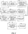
- Fig. 2 A method of fabricating demisable fuel systems with pressurized aluminum propellant tanks and with COPV tanks is shown in Fig. 2 .
- the process starts with the procurement of aluminum alloy material, preferably sheet stock. (Step 30).
- Liquid propellant tank shell sections are then fabricated from the sheet stock, preferably by spinning and other methods known in the art (Step 32).
- a preferred thickness of the tank sections is between about 0.9 millimeters and 7 millimeters.
- Aluminum alloys suitable for the tank include, but are not limited to, 6061, 2219, and 2014 alloys.
- the interior surface or portions of the interior surface of the tank shell sections are then coated with a titanium based coating.
- titanium based coatings for the tank shell interior sections include, but are not limited to, pure titanium and Ti-6Al-4V and Ti-15V-3Cr-3Sn-3Al alloys.
- the thickness of the titanium based coating is between about 1 micron and about 10 microns.
- Aluminum PMD components such as vanes, sponges, traps, troughs, and others are then fabricated or acquired from qualified vendors. (Step 36).
- Aluminum alloys suitable for the PMD components include, but are not limited to, 6061, 2219, and 2014 alloys.
- a titanium based coating is then applied to the PMD components (Step 38).
- Suitable coatings include, but are not limited to, pure titanium and Ti-6Al-4V and Ti-15V-3Cr-3Sn-3Al alloys (Step 38).
- the PMD components are then assembled into PMD fixtures by processes known in the art (Step 40) and then installed into the tank shell components (Step 42).
- the PMD components are installed into the tank shell components by attaching the components to the tank shell by welding, braising, mechanical fasteners, or other methods known in the art (Step 42).
- the tank shell components containing installed PMD devices are then assembled and joined into finished tanks and liners (Step 44). Assembling and jointing comprises gas tungsten arc welding, electron beam welding, laser beam welding and other methods known in the art. If the finished product is a tank, the tank is then qualified for service (Step 46). If the finished product is a COPV, the assembled liner containing installed PMD devices is then overwrapped with composite fibers to form a COPV (Step 48). The COPV is then qualified for service (Step 50).
Landscapes
- Engineering & Computer Science (AREA)
- Chemical & Material Sciences (AREA)
- Combustion & Propulsion (AREA)
- Mechanical Engineering (AREA)
- General Engineering & Computer Science (AREA)
- Remote Sensing (AREA)
- Aviation & Aerospace Engineering (AREA)
- Filling Or Discharging Of Gas Storage Vessels (AREA)
- Other Surface Treatments For Metallic Materials (AREA)
- Physical Vapour Deposition (AREA)
Description
- Satellite fuel tanks are complex devices that use various means to deliver fuel to propulsion systems of the space craft. In a zero or low gravity environment, separating the liquids from pressurizing gases in order to deliver them in sufficient quantities to support mission requirements is difficult. Often, this process is performed with a propellant management device (PMD) that utilizes surface tension and capillary action to transport the liquid fuel. It is imperative that the tank and PMD materials are compatible and wettable with the liquid fuel chemicals such as hydrazine. It is known in the art that materials such as titanium and titanium alloys are used for this purpose because of their high chemical compatibility and wettability with hydrazine and other propellants and oxidizers used to fuel satellites.
- One requirement for low earth orbiting (LEO) satellites is the ability to retain enough fuel for a final de-orbit maneuver at end of life. The purpose of this activity is to position the space craft in a controlled re-entry trajectory that allows it to fall into the ocean, thereby reducing the loss of life and property should the debris fall into a populated area. Unfortunately, the amount of fuel needed for this final action could otherwise enable the space craft to remain functional for a period of up to several years if the end of mission re-entry were uncontrolled. Uncontrolled re-entry requirements are that all but a negligible portion of the space craft burn up (demise) during re-entry.
- Designs for demise programs have emphasized replacing components fabricated from higher melting point materials such as steels and titanium with lower melting material such as aluminum to increase demisability during re-entry. The fuel tanks for the NASA Global Precipitation Measurement satellite (GPM) have been designed with aluminum fuel tanks and PMDs for this purpose. A special surface treatment to increase the chemical compatibility and wettability of aluminum alloys used for the GPM components has been expensive, labor intensive, and difficult to verify in completed tank structures.
-
GB 2270089 -
US 5279323 discloses a liquid storage tank for use on a spacecraft, provided with a transfer apparatus comprising gathering vanes, an array of fins, and a sponge structure formed from panels. The transfer apparatus transfers liquid from the inner surface of the tank to the vicinity of an outlet line. -
WO 2010/063449 discloses a tank for receiving, storing and discharging liquids and/or viscous substances, in particular fuel or propellant or drinking water, having a casing and at least one baffle plate which is arranged in an interior of the tank, on the inner side of the casing, and has one end directed towards an outlet opening of the tank, and extends into a region which is adjacent to or adjoins the outlet opening of the tank. A flexible element is arranged between the at least one baffle plate and the inner side of the casing in order to cover a gap, corner, or similar space formed between the at least one baffle plate and the inner side of the casing. -
JP 2010/247719 - In accordance with a first aspect of the present invention there is provided a demisable fuel supply system having a liquid storage tank and propellant management devices. The liquid storage tank and propellant management devices are fabricated from aluminum alloys. Selected areas of the inside surface of the liquid storage tank and surfaces of the propellant management devices are coated with a titanium based coating to guarantee high wettability of and corrosion protection against the propellant.
- In accordance with a second aspect of the present invention there is provided a method of making a demisable fuel supply system comprising: fabricating liquid storage tank sections from an aluminum alloy; fabricating propellant management device components from an aluminum alloy; attaching the propellant management device components to the interior surfaces of the liquid storage tank sections; coating selected storage tank section interiors and/or the propellant management device components with a highly wettable and corrosion resistant titanium based coating; assembling the populated storage tank sections to form a finished liquid storage tank.
-
-
FIG. 1 is a schematic illustration of a propellant tank with propellant management components therein. -
FIG. 1A is a schematic sketch of a top view of a sponge propellant management component. -
FIG. 1B is a schematic sketch of a side view of a sponge propellant management component. -
FIG. 2 is a diagram showing fabrication steps of a demisable fuel supply system. - National and international agreements have emphasized end of mission re-entry from near earth orbit (NEO) to minimize hazardous orbital debris. Controlled re-entry, whereby the space craft is put into a trajectory with a predetermined landing site, such as an ocean, has been the accepted practice in order to minimize personal or property damage. Uncontrolled re-entry requires that the space craft completely burn up (demise) before impact. A demisable satellite mission can be extended for up to a number of years because of the fuel saved by not having to position the spacecraft in an orientation for a proper trajectory during controlled re-entry.
- The recent NASA Global Precipitation Measurement (GPM) satellite has been the first to design according to a "design for demise" (DfD) specification for exactly the above reasons. In DfD designs, low melting metals and other materials comprise most or all of the structures. Aluminum is favored because of its relatively low melting point. Steel and titanium satellite components do not demise during re-entry. A fuel supply system for the GPM satellite comprises a pressurized composite over-wrapped pressure vessel (COPV), an aluminum tank liner and aluminum propellant management devices (PMD). In a zero gravity environment, fuel transport in PMD systems is by capillary action and wettability of the tank and PMD components by the propellant is an absolute necessity for the fuel systems to operate. Unfortunately, the wettability of hydrazine and other fuels and oxidizers on normal clean aluminum surfaces is insufficient to allow aluminum PMD systems to work. A solution was found, however, that creates a hydrated oxide surface layer on certain aluminum alloys that achieved sufficient wettability and allowed the aluminum PMD systems to function. The surface treatment is expensive, labor intensive, and fragile. Exposure to normal "shop air" for example, can render the surface non-wettable and would disable the GPM PMD before launch. Additionally, exposure to common chemicals normally used in processing and testing satellite fuel tanks are destructive to the hydrated oxide coated aluminum surfaces. Finally, the wettability of the treated aluminum surfaces cannot be directly tested after the tank has been constructed and use of similarly treated test coupons is an inferior and marginally acceptable qualification and certification procedure.
- An embodiment of this invention is to coat the tank interior and all internal PMD structures with a thin layer of a titanium based coating before final assembly, thereby guaranteeing acceptable wettability and corrosion resistance of the propellant delivery system. Another embodiment is to coat only the PMD and all its fluid communication components and not the entire tank liner.
- An example of a propellant delivery system will now be discussed. The system is only an example and is not to be taken as limiting in any respect to propellant delivery systems now known or to be developed. A schematic sketch of
propellant delivery system 10 is shown inFIG. 1 .Propellant delivery system 10 is a monopropellant delivery system where a single fuel such as hydrazine is used. Bipropellant propulsion systems using a fuel and an oxidizer are also in common use.Delivery system 10 includestank 12, inletgas flow line 14, outletliquid flow line 16,propellant 18,vanes 20, andsponge 22. Vanes 20 deliverpropellant 18 tosponge 22 where collected and storedpropellant 18 insponge 22 is drawn fromliquid flow line 16 when required by the propulsion system. - The demisable
propellant delivery system 10 is preferably fabricated from an aluminum alloy. Aluminum alloys suitable for this purpose include, but are not limited to, 6061, 2219, and 2014 alloys. - In zero gravity environments, surface tension forces and capillary action are necessary driving forces to deliver propellant in space crafts such as satellites. A primary function of propellant management devices is to deliver fuel without gas bubbles to a propulsion system. Gas entrained in a fuel line may result in engine malfunction. Normal filters for this purpose are titanium alloy screens where liquid passes through the screens by capillary action and gas bubbles are left behind.
-
Vanes 20 may be simple thin metallic ribs aligned perpendicular totank shell 12 as shown inFIG. 1 . The propellant collects at the intersection ofvane 20 andtank shell 12 and is held in place by surface tension and meniscus forces. Collectingsponge 22 may be a radial assembly of vertical panels.FIGS 1A and 1B are top and side view, respectively, ofsponge 22. In a similar fashion, propellant is held in place by surface tension and meniscus forces and fills area inside dottedcircle 24 along the entire length ofsponge 22. Other collection reservoirs (not shown) are traps and troughs. Vanes, sponges, traps and troughs are described by D. E. Jaekle, Jr. in American Institute of Aeronautics and Astronautics Papers AIAA-91-2172, AIAA-93-1970, and AIAA-95-2531, respectively, for instance. - As noted above, an embodiment of the present invention is to coat all surfaces of the fuel supply system that are in contact with propellant with a titanium based coating in order to guarantee wettability and corrosion resistance throughout the life of a mission. Preferable titanium based coatings are, but are not limited to, pure titanium and Ti-6Al-4V, and Ti-15V-3Cr-3Sn-3Al alloys. Deposition methods include physical vapor deposition, chemical vapor deposition, sputtering, electroplating, and other methods known in the art. During re-entry, the thin titanium based coating becomes an inconsequential component of the structure as the aluminum components burn up. As mentioned above, another embodiment is to coat only PMD components and fluid communication surfaces with the titanium based coating to ensure acceptable fuel supply during the mission.
- Two tank configurations are preferred for satellite fuel systems. One embodiment is a simple aluminum pressurized tank containing propellant management devices (PMD). The other embodiment is an aluminum pressurized tank surrounded by an overwrap of a composite containment shell called a composite overwrap pressure vessel or COPV. In a COPV, the aluminum tank is called a liner in the art.
- A method of fabricating demisable fuel systems with pressurized aluminum propellant tanks and with COPV tanks is shown in
Fig. 2 . The process starts with the procurement of aluminum alloy material, preferably sheet stock. (Step 30). Liquid propellant tank shell sections are then fabricated from the sheet stock, preferably by spinning and other methods known in the art (Step 32). A preferred thickness of the tank sections is between about 0.9 millimeters and 7 millimeters. Aluminum alloys suitable for the tank include, but are not limited to, 6061, 2219, and 2014 alloys. - Optionally, the interior surface or portions of the interior surface of the tank shell sections are then coated with a titanium based coating. (Step 34). Preferably, titanium based coatings for the tank shell interior sections include, but are not limited to, pure titanium and Ti-6Al-4V and Ti-15V-3Cr-3Sn-3Al alloys. The thickness of the titanium based coating is between about 1 micron and about 10 microns.
- Aluminum PMD components such as vanes, sponges, traps, troughs, and others are then fabricated or acquired from qualified vendors. (Step 36). Aluminum alloys suitable for the PMD components include, but are not limited to, 6061, 2219, and 2014 alloys.
- A titanium based coating is then applied to the PMD components (Step 38). Suitable coatings include, but are not limited to, pure titanium and Ti-6Al-4V and Ti-15V-3Cr-3Sn-3Al alloys (Step 38). The PMD components are then assembled into PMD fixtures by processes known in the art (Step 40) and then installed into the tank shell components (Step 42). The PMD components are installed into the tank shell components by attaching the components to the tank shell by welding, braising, mechanical fasteners, or other methods known in the art (Step 42).
- The tank shell components containing installed PMD devices are then assembled and joined into finished tanks and liners (Step 44). Assembling and jointing comprises gas tungsten arc welding, electron beam welding, laser beam welding and other methods known in the art. If the finished product is a tank, the tank is then qualified for service (Step 46). If the finished product is a COPV, the assembled liner containing installed PMD devices is then overwrapped with composite fibers to form a COPV (Step 48). The COPV is then qualified for service (Step 50).
- While the invention has been described with reference to an exemplary embodiment(s), it will be understood by those skilled in the art that various changes may be made and equivalents may be substituted for elements thereof without departing from the scope of the invention as defined by the claims. In addition, many modifications may be made to adapt a particular situation or material to the teachings of the invention without departing from the essential scope thereof. Therefore, it is intended that the invention not be limited to the particular embodiment(s) disclosed, but that the invention will include all embodiments falling within the scope of the appended claims.
Claims (15)
- A demisable fuel supply system (10) for a satellite, comprising:an aluminum alloy liquid storage tank (12) for storing a liquid propellant; andaluminum alloy propellant management devices (20,22); characterised in that the fuel supply system comprisesa highly wettable and corrosion resistant titanium based coating covering selected internal surfaces of the liquid storage tank and propellant management devices.
- The demisable fuel supply system of claim 1, wherein the titanium based coating is selected from the group consisting of pure titanium, and Ti-6Al-4V, and Ti-15V-3Cr-3Sn-3Al alloys; preferably wherein the titanium based coating is Ti-6Al-4V alloy.
- The demisable fuel supply system of claim 1 or 2, wherein the titanium based coating has a thickness of from 1 micron to 10 microns.
- The demisable fuel supply system of claim 1, 2 or 3, wherein the titanium based coating is deposited by at least one of physical vapor deposition, chemical vapor deposition, sputtering, electroplating, and ion beam deposition.
- The demisable fuel supply system of any preceding claim, wherein the aluminum alloy is selected from the group consisting of 6061, 2219, and 2014 alloys; preferably wherein the aluminum alloy is 6061 alloy.
- The demisable fuel supply system of any preceding claim, wherein the liquid storage tank (12) has a thickness of from 0.9 millimeters to 7 millimeters.
- The demisable fuel supply system of any preceding claim, wherein the liquid propellant comprises mono or bipropellant fuels.
- The demisable fuel supply system of claim 7, wherein the mono propellant fuel comprises hydrazine.
- A method of making a demisable fuel supply system (10) for a satellite, comprising:fabricating liquid storage tank (12) sections from an aluminum alloy;fabricating propellant management device components (20,22) from an aluminum alloy;attaching the propellant management device components to the interior surfaces of the liquid storage tank sections;coating selected storage tank section interiors and/or the propellant management device components with a highly wettable and corrosion resistant titanium based coating;assembling the populated storage tank sections to form a finished liquid storage tank.
- The method of claim 9, wherein the aluminum alloy is selected from a group consisting of 6061, 2215, and 2014 alloys; preferably wherein the aluminum alloy is 6061 alloy.
- The method of claim 9 or 10, wherein the propellant management device components (20,22) are attached to the storage tank (12) sections by welding, brazing, or with mechanical fasteners.
- The method of claim 9, 10 or 11, wherein the titanium based coating is selected from a group consisting of pure titanium, Ti-6Al-4V, and Ti-15V-3Cr-3Sn-3Al alloys.
- The method of claim 9, 10, 11 or 12, wherein the titanium based coating has a thickness of from 1 micron to 10 microns, and/or wherein the liquid storage tank has a thickness from 0.9 millimeters to 7 millimeters.
- The method of any of claims 9 to 13, wherein the liquid storage tank(12) sections are assembled by at least one of gas tungsten arc welding, electron beam welding, and laser beam welding.
- The method of any of claims 9 to 14, wherein the titanium based coating is deposited by at least one of physical vapor deposition, chemical vapor deposition, sputtering, electroplating, and ion beam deposition.
Applications Claiming Priority (1)
| Application Number | Priority Date | Filing Date | Title |
|---|---|---|---|
| US13/052,862 US8511504B2 (en) | 2011-03-21 | 2011-03-21 | Demisable fuel supply system |
Publications (2)
| Publication Number | Publication Date |
|---|---|
| EP2502829A1 EP2502829A1 (en) | 2012-09-26 |
| EP2502829B1 true EP2502829B1 (en) | 2020-10-21 |
Family
ID=45936840
Family Applications (1)
| Application Number | Title | Priority Date | Filing Date |
|---|---|---|---|
| EP12160308.8A Not-in-force EP2502829B1 (en) | 2011-03-21 | 2012-03-20 | Demisable fuel supply system |
Country Status (4)
| Country | Link |
|---|---|
| US (1) | US8511504B2 (en) |
| EP (1) | EP2502829B1 (en) |
| CN (1) | CN102691592B (en) |
| RU (1) | RU2581295C1 (en) |
Families Citing this family (20)
| Publication number | Priority date | Publication date | Assignee | Title |
|---|---|---|---|---|
| EP2644511B1 (en) * | 2012-03-28 | 2018-09-19 | Keystone Engineering Company | Demisable fuel supply system |
| US9840752B2 (en) * | 2014-05-27 | 2017-12-12 | Keystone Engineering Company | Method and apparatus for performing a localized post-weld heat treatment on a thin wall metallic cylinder |
| JP6590502B2 (en) * | 2015-03-31 | 2019-10-16 | 三菱重工業株式会社 | Propellant tank and spacecraft for spacecraft |
| CN104863752A (en) * | 2015-04-20 | 2015-08-26 | 西安交通大学 | Low-temperature liquid storage box capable of improving gas pressurization effect |
| US10479532B2 (en) * | 2015-05-07 | 2019-11-19 | Keystone Engineering Company | Stress relieved welds in positive expulsion fuel tanks with rolling metal diaphragms |
| CN107152606A (en) * | 2017-05-24 | 2017-09-12 | 北京零壹空间科技有限公司 | A kind of space cryogenic propellant tank |
| FR3078525B1 (en) * | 2018-03-05 | 2020-03-06 | Centre Technique Des Industries Mecaniques | BOTTOM FLOW ASSEMBLY FOR LIQUID FUEL TANK |
| US11346306B1 (en) | 2019-01-03 | 2022-05-31 | Ball Aerospace & Technologies Corp. | Chemical and cold gas propellant systems and methods |
| US11498705B1 (en) | 2019-05-09 | 2022-11-15 | Ball Aerospace & Technology Corp. | On orbit fluid propellant dispensing systems and methods |
| CN111232250B (en) * | 2020-01-17 | 2021-10-29 | 上海空间推进研究所 | Plate type surface tension storage tank |
| RU2738247C1 (en) * | 2020-06-05 | 2020-12-14 | Акционерное общество "Государственный космический научно-производственный центр им. М.В. Хруничева" | Fuel tank of liquid propulsion units of heavy lift rockets |
| CN111674571B (en) * | 2020-06-10 | 2021-07-27 | 西安交通大学 | An adaptive management device for propellant in an aircraft tank |
| DE102020132644A1 (en) | 2020-12-08 | 2022-06-09 | Deutsches Zentrum für Luft- und Raumfahrt e.V. | Improving destructibility during atmospheric entry flight by coating component surfaces |
| AT524873B1 (en) | 2021-05-06 | 2022-10-15 | Peak Tech Gmbh | Wrapping made of a fiber composite plastic for a space container shell |
| US12012233B2 (en) | 2021-05-10 | 2024-06-18 | Ball Aerospace & Technologies Corp. | Active on orbit fluid propellant management and refueling systems and methods |
| CN113618381B (en) * | 2021-08-30 | 2022-06-10 | 吉林大学 | Device for maintaining mounting precision of main shaft of moving mechanism and assembling method thereof |
| US11945606B1 (en) | 2021-10-19 | 2024-04-02 | Ball Aerospace & Technologies Corp. | Electric propulsion based spacecraft propulsion systems and methods utilizing multiple propellants |
| CN116238713B (en) * | 2022-12-14 | 2025-08-26 | 上海空间推进研究所 | Propellant management device and aircraft meeting ultra-large flow conditions |
| CN117404208B (en) * | 2023-10-19 | 2024-07-26 | 北京天兵科技有限公司 | Barrel section structure for embossing sheet metal of storage tank, preparation process, storage tank and carrier rocket |
| CN120793234A (en) * | 2025-07-07 | 2025-10-17 | 北京控制工程研究所 | Concentric common-bottom plate type surface tension storage box |
Family Cites Families (44)
| Publication number | Priority date | Publication date | Assignee | Title |
|---|---|---|---|---|
| US3097766A (en) * | 1959-09-17 | 1963-07-16 | Curtiss Wright Corp | Pre-filled propellant tank for rockets |
| US3229014A (en) * | 1962-05-31 | 1966-01-11 | Dilectrix Corp | Methods of making a flexible container |
| US3240644A (en) * | 1962-11-02 | 1966-03-15 | Specialties Dev Corp | Method of making pressure vessels |
| US3392865A (en) * | 1965-10-29 | 1968-07-16 | Nasa Usa | Filament-wound container |
| US3356252A (en) * | 1967-01-04 | 1967-12-05 | Dilectrix Corp | High impermeability coatings and supported fabricated objects of polytetrafluoroethylene |
| US3486302A (en) * | 1968-02-26 | 1969-12-30 | Martin Marietta Corp | Zero or reduced gravity storage system for two phase fluid |
| US3715231A (en) * | 1971-05-28 | 1973-02-06 | Us Army | Storage of liquid hydrazine rocket fuels |
| US3854905A (en) * | 1972-04-24 | 1974-12-17 | Rca Corp | Storage system for two phase fluids |
| US4168718A (en) * | 1978-07-11 | 1979-09-25 | Nasa | Passive propellant system |
| US4235943A (en) * | 1979-02-22 | 1980-11-25 | United Technologies Corporation | Thermal spray apparatus and method |
| FR2484961A1 (en) * | 1980-06-20 | 1981-12-24 | Europ Propulsion | SURFACE TANK |
| DE3146262A1 (en) * | 1981-11-21 | 1983-05-26 | Erno-Raumfahrttechnik Gmbh, 2800 Bremen | "FUEL TANK" |
| US4672906A (en) * | 1984-06-08 | 1987-06-16 | Mitsubishi Jukogyo Kabushiki Kaisha | Freight carrier's hull construction for carrying cryogenic or high temperature freight |
| US4715399A (en) * | 1984-10-29 | 1987-12-29 | Jaekle Jr Don E | Liquid-propellant management system for rockets and space vehicles |
| US4743278A (en) * | 1986-06-16 | 1988-05-10 | Ford Aerospace & Communications Corporation | Passive propellant management system |
| US4901762A (en) * | 1988-10-03 | 1990-02-20 | Lockheed Missiles & Space Company, Inc. | Liquid-propellant management apparatus |
| DE3837137A1 (en) * | 1988-11-02 | 1990-05-03 | Erno Raumfahrttechnik Gmbh | FUEL TANK FOR STORING AGGRESSIVE LIQUIDS |
| US5005362A (en) * | 1990-03-20 | 1991-04-09 | The Boc Group, Inc. | Cryogenic storage container |
| US5150812A (en) * | 1990-07-05 | 1992-09-29 | Hoechst Celanese Corporation | Pressurized and/or cryogenic gas containers and conduits made with a gas impermeable polymer |
| US5263329A (en) * | 1991-12-19 | 1993-11-23 | Lockheed Missiles & Space Company, Inc. | Flow management apparatus for cryogenic liquid |
| US5279323A (en) | 1991-12-19 | 1994-01-18 | Lockheed Missiles & Space Company, Inc. | Liquid management apparatus for spacecraft |
| GB2270089A (en) | 1992-08-24 | 1994-03-02 | Gen Electric | Producing metal coated propulsion tanks for aerospace applications |
| US5441219A (en) * | 1993-05-27 | 1995-08-15 | Martin Marietta Corporation | Method for attaching metallic tubing to nonmetallic pressure vessel, and pressure vessel made by the method |
| US5427334A (en) * | 1993-09-17 | 1995-06-27 | Martin Marieta Corporation | Method for making nonmetallic pressure vessel with integral propellant management vane, and pressure vessel made by the method |
| US5822838A (en) * | 1996-02-01 | 1998-10-20 | Lockheed Martin Corporation | High performance, thin metal lined, composite overwrapped pressure vessel |
| US5901557A (en) * | 1996-10-04 | 1999-05-11 | Mcdonnell Douglas Corporation | Passive low gravity cryogenic storage vessel |
| US6082676A (en) * | 1998-02-25 | 2000-07-04 | Kistler Aerospace Corporation | Cryogenic tanks for launch vehicles |
| US6499287B1 (en) * | 1999-05-25 | 2002-12-31 | Zachary R. Taylor | Integrated tankage for propulsion vehicles and the like |
| US6321930B1 (en) * | 1999-09-20 | 2001-11-27 | Lockheed Martin Corporation | Cryogenic tank joint |
| US6422514B1 (en) * | 2000-07-26 | 2002-07-23 | Lockheed Martin Corportation | Common bulkhead cryogenic propellant tank |
| US6658863B2 (en) * | 2001-05-22 | 2003-12-09 | Lockheed Martin Corporation | Airborne gas storage and supply system |
| RU2238225C1 (en) * | 2003-03-25 | 2004-10-20 | Федеральное государственное унитарное предприятие "Государственный космический научно-производственный центр им. М.В. Хруничева" | Load-bearing shell for propellant (fuel) tank and method of manufacture of such shell |
| JP4359442B2 (en) * | 2003-03-31 | 2009-11-04 | 株式会社フジミインコーポレーテッド | Thermal spray powder and method for forming thermal spray coating using the same |
| DE10345958A1 (en) * | 2003-10-02 | 2005-04-21 | Magna Steyr Fahrzeugtechnik Ag | Mobile tank for cryogenic liquids |
| US20080256960A1 (en) * | 2004-06-11 | 2008-10-23 | Greason Jeffrey K | Vehicles incorporating tanks for carrying cryogenic fluids and methods for forming such tanks |
| ITRM20050347A1 (en) * | 2005-06-30 | 2007-01-01 | Finmeccanica Spa | INTEGRATED PLASTIC LINER FOR PROPELLENT TANKS FOR PLATFORMS AND SPACE TRANSPORT SYSTEMS. |
| DE102005035356B3 (en) * | 2005-07-28 | 2006-10-19 | Eads Space Transportation Gmbh | Fuel tank for storing aggressive media used for powering spacecraft comprises an outlet with holes for connecting an outlet tube to a collecting container |
| DE102005044534B3 (en) * | 2005-09-17 | 2007-06-06 | Astrium Gmbh | Fuel tank for cryogenic liquids |
| JP2009529605A (en) * | 2005-11-28 | 2009-08-20 | マセソン トライ−ガス, インコーポレイテッド | Gas storage container lining formed by chemical vapor deposition |
| DE102005062092B3 (en) * | 2005-12-22 | 2007-03-29 | Eads Space Transportation Gmbh | Aggressive storable propellant e.g. hydrazine, receiving and storage tank for operation of e.g. satellite, has tank outlet with connecting-or opening channels and helical channel, where channels connect reservoir with outlet pipe of outlets |
| US20080014420A1 (en) * | 2006-07-11 | 2008-01-17 | Ion Technology (Hong Kong) Limited | Surface treatment for titanium or titanium-alloys |
| DE102008059880B4 (en) | 2008-12-01 | 2010-10-21 | Mt Aerospace Ag | Containers for receiving, storing and dispensing liquids and viscous substances, in particular fuel or fuel or drinking water, and the use thereof |
| JP5448544B2 (en) | 2009-04-17 | 2014-03-19 | 三菱重工業株式会社 | Composite materials and fuel tanks for spacecraft |
| RU95313U1 (en) * | 2010-03-03 | 2010-06-27 | Открытое акционерное общество "Композит" | CAPSULE FOR MAKING A SEAMLESS FUEL TANK |
-
2011
- 2011-03-21 US US13/052,862 patent/US8511504B2/en not_active Expired - Fee Related
-
2012
- 2012-03-20 EP EP12160308.8A patent/EP2502829B1/en not_active Not-in-force
- 2012-03-20 RU RU2012110594/06A patent/RU2581295C1/en active
- 2012-03-21 CN CN201210075527.1A patent/CN102691592B/en not_active Expired - Fee Related
Non-Patent Citations (1)
| Title |
|---|
| None * |
Also Published As
| Publication number | Publication date |
|---|---|
| RU2012110594A (en) | 2013-09-27 |
| CN102691592B (en) | 2016-08-31 |
| RU2581295C1 (en) | 2016-04-20 |
| CN102691592A (en) | 2012-09-26 |
| US8511504B2 (en) | 2013-08-20 |
| EP2502829A1 (en) | 2012-09-26 |
| US20120241459A1 (en) | 2012-09-27 |
Similar Documents
| Publication | Publication Date | Title |
|---|---|---|
| US8511504B2 (en) | Demisable fuel supply system | |
| US8534489B2 (en) | Demisable fuel supply system | |
| Henson et al. | Materials for launch vehicle structures | |
| CA2037005A1 (en) | Geostationary earth observation satellite incorporating multiple thruster liquid propellant apogee maneuver system | |
| Ballinger et al. | Review and history of PSI elastomeric diaphragm tanks | |
| US5921167A (en) | Hermetic shear seal for piston displacement fuel tank | |
| De Brock et al. | A survey of current developments in surface tension devices for propellant acquisition | |
| EP2644511B1 (en) | Demisable fuel supply system | |
| Freeman Jr et al. | Single-stage-to-orbit—A step closer | |
| Dankanich et al. | NASA in-space advanced chemical propulsion development in recent years | |
| Marquardt et al. | An overview of Ball Aerospace cryogen storage and delivery systems | |
| Benton et al. | Design and manufacture of a propellant tank assembly | |
| Debreceni et al. | Design and development of a communications satellite propellant tank | |
| Valentini et al. | Green propellant thruster design for LEO platforms active debris removal | |
| Regnier et al. | Design and development of a passive propellant management system | |
| Tam et al. | Design and manufacture of an oxidizer tank with a surface tension PMD | |
| Stark | Low-G fluid transfer technology study | |
| Estes et al. | Summary of the Development of a Demiseable Composite Overwrapped Hydrazine Tank for the Global Precipitation Measurement Mission from Concept to Delivery | |
| Debreceni et al. | Design and development of a PMD-type bipropellant tank | |
| Dunn | Requirements for Spacecraft Materials | |
| Debreceni et al. | Tank for an advanced communications satellite | |
| de Iaco Veris | Interconnecting Components and Structures | |
| Nordmark | Fatigue of aluminum with alclad or sprayed coatings | |
| Sivolella | Maneuvering in space: the orbital maneuvering system and reaction control system | |
| Tam et al. | Low-Cost tankage provided for recent discovery missions |
Legal Events
| Date | Code | Title | Description |
|---|---|---|---|
| PUAI | Public reference made under article 153(3) epc to a published international application that has entered the european phase |
Free format text: ORIGINAL CODE: 0009012 |
|
| AK | Designated contracting states |
Kind code of ref document: A1 Designated state(s): AL AT BE BG CH CY CZ DE DK EE ES FI FR GB GR HR HU IE IS IT LI LT LU LV MC MK MT NL NO PL PT RO RS SE SI SK SM TR |
|
| AX | Request for extension of the european patent |
Extension state: BA ME |
|
| 17P | Request for examination filed |
Effective date: 20130326 |
|
| RAP1 | Party data changed (applicant data changed or rights of an application transferred) |
Owner name: KEYSTONE ENGINEERING COMPANY |
|
| STAA | Information on the status of an ep patent application or granted ep patent |
Free format text: STATUS: EXAMINATION IS IN PROGRESS |
|
| 17Q | First examination report despatched |
Effective date: 20180104 |
|
| GRAP | Despatch of communication of intention to grant a patent |
Free format text: ORIGINAL CODE: EPIDOSNIGR1 |
|
| STAA | Information on the status of an ep patent application or granted ep patent |
Free format text: STATUS: GRANT OF PATENT IS INTENDED |
|
| RIC1 | Information provided on ipc code assigned before grant |
Ipc: F02K 9/60 20060101ALI20200409BHEP Ipc: F17C 13/00 20060101ALI20200409BHEP Ipc: B64G 1/40 20060101AFI20200409BHEP |
|
| INTG | Intention to grant announced |
Effective date: 20200430 |
|
| RIN1 | Information on inventor provided before grant (corrected) |
Inventor name: TUTTLE, WAYNE H. |
|
| GRAS | Grant fee paid |
Free format text: ORIGINAL CODE: EPIDOSNIGR3 |
|
| GRAA | (expected) grant |
Free format text: ORIGINAL CODE: 0009210 |
|
| STAA | Information on the status of an ep patent application or granted ep patent |
Free format text: STATUS: THE PATENT HAS BEEN GRANTED |
|
| AK | Designated contracting states |
Kind code of ref document: B1 Designated state(s): AL AT BE BG CH CY CZ DE DK EE ES FI FR GB GR HR HU IE IS IT LI LT LU LV MC MK MT NL NO PL PT RO RS SE SI SK SM TR |
|
| REG | Reference to a national code |
Ref country code: GB Ref legal event code: FG4D |
|
| REG | Reference to a national code |
Ref country code: CH Ref legal event code: EP |
|
| REG | Reference to a national code |
Ref country code: IE Ref legal event code: FG4D |
|
| REG | Reference to a national code |
Ref country code: AT Ref legal event code: REF Ref document number: 1325615 Country of ref document: AT Kind code of ref document: T Effective date: 20201115 |
|
| REG | Reference to a national code |
Ref country code: DE Ref legal event code: R096 Ref document number: 602012072861 Country of ref document: DE |
|
| REG | Reference to a national code |
Ref country code: AT Ref legal event code: MK05 Ref document number: 1325615 Country of ref document: AT Kind code of ref document: T Effective date: 20201021 |
|
| REG | Reference to a national code |
Ref country code: NL Ref legal event code: MP Effective date: 20201021 |
|
| PG25 | Lapsed in a contracting state [announced via postgrant information from national office to epo] |
Ref country code: GR Free format text: LAPSE BECAUSE OF FAILURE TO SUBMIT A TRANSLATION OF THE DESCRIPTION OR TO PAY THE FEE WITHIN THE PRESCRIBED TIME-LIMIT Effective date: 20210122 Ref country code: NO Free format text: LAPSE BECAUSE OF FAILURE TO SUBMIT A TRANSLATION OF THE DESCRIPTION OR TO PAY THE FEE WITHIN THE PRESCRIBED TIME-LIMIT Effective date: 20210121 Ref country code: PT Free format text: LAPSE BECAUSE OF FAILURE TO SUBMIT A TRANSLATION OF THE DESCRIPTION OR TO PAY THE FEE WITHIN THE PRESCRIBED TIME-LIMIT Effective date: 20210222 Ref country code: NL Free format text: LAPSE BECAUSE OF FAILURE TO SUBMIT A TRANSLATION OF THE DESCRIPTION OR TO PAY THE FEE WITHIN THE PRESCRIBED TIME-LIMIT Effective date: 20201021 Ref country code: RS Free format text: LAPSE BECAUSE OF FAILURE TO SUBMIT A TRANSLATION OF THE DESCRIPTION OR TO PAY THE FEE WITHIN THE PRESCRIBED TIME-LIMIT Effective date: 20201021 Ref country code: FI Free format text: LAPSE BECAUSE OF FAILURE TO SUBMIT A TRANSLATION OF THE DESCRIPTION OR TO PAY THE FEE WITHIN THE PRESCRIBED TIME-LIMIT Effective date: 20201021 |
|
| REG | Reference to a national code |
Ref country code: LT Ref legal event code: MG4D |
|
| PG25 | Lapsed in a contracting state [announced via postgrant information from national office to epo] |
Ref country code: BG Free format text: LAPSE BECAUSE OF FAILURE TO SUBMIT A TRANSLATION OF THE DESCRIPTION OR TO PAY THE FEE WITHIN THE PRESCRIBED TIME-LIMIT Effective date: 20210121 Ref country code: AT Free format text: LAPSE BECAUSE OF FAILURE TO SUBMIT A TRANSLATION OF THE DESCRIPTION OR TO PAY THE FEE WITHIN THE PRESCRIBED TIME-LIMIT Effective date: 20201021 Ref country code: ES Free format text: LAPSE BECAUSE OF FAILURE TO SUBMIT A TRANSLATION OF THE DESCRIPTION OR TO PAY THE FEE WITHIN THE PRESCRIBED TIME-LIMIT Effective date: 20201021 Ref country code: IS Free format text: LAPSE BECAUSE OF FAILURE TO SUBMIT A TRANSLATION OF THE DESCRIPTION OR TO PAY THE FEE WITHIN THE PRESCRIBED TIME-LIMIT Effective date: 20210221 Ref country code: PL Free format text: LAPSE BECAUSE OF FAILURE TO SUBMIT A TRANSLATION OF THE DESCRIPTION OR TO PAY THE FEE WITHIN THE PRESCRIBED TIME-LIMIT Effective date: 20201021 Ref country code: LV Free format text: LAPSE BECAUSE OF FAILURE TO SUBMIT A TRANSLATION OF THE DESCRIPTION OR TO PAY THE FEE WITHIN THE PRESCRIBED TIME-LIMIT Effective date: 20201021 Ref country code: SE Free format text: LAPSE BECAUSE OF FAILURE TO SUBMIT A TRANSLATION OF THE DESCRIPTION OR TO PAY THE FEE WITHIN THE PRESCRIBED TIME-LIMIT Effective date: 20201021 |
|
| PG25 | Lapsed in a contracting state [announced via postgrant information from national office to epo] |
Ref country code: HR Free format text: LAPSE BECAUSE OF FAILURE TO SUBMIT A TRANSLATION OF THE DESCRIPTION OR TO PAY THE FEE WITHIN THE PRESCRIBED TIME-LIMIT Effective date: 20201021 |
|
| REG | Reference to a national code |
Ref country code: DE Ref legal event code: R097 Ref document number: 602012072861 Country of ref document: DE |
|
| PG25 | Lapsed in a contracting state [announced via postgrant information from national office to epo] |
Ref country code: SK Free format text: LAPSE BECAUSE OF FAILURE TO SUBMIT A TRANSLATION OF THE DESCRIPTION OR TO PAY THE FEE WITHIN THE PRESCRIBED TIME-LIMIT Effective date: 20201021 Ref country code: RO Free format text: LAPSE BECAUSE OF FAILURE TO SUBMIT A TRANSLATION OF THE DESCRIPTION OR TO PAY THE FEE WITHIN THE PRESCRIBED TIME-LIMIT Effective date: 20201021 Ref country code: LT Free format text: LAPSE BECAUSE OF FAILURE TO SUBMIT A TRANSLATION OF THE DESCRIPTION OR TO PAY THE FEE WITHIN THE PRESCRIBED TIME-LIMIT Effective date: 20201021 Ref country code: SM Free format text: LAPSE BECAUSE OF FAILURE TO SUBMIT A TRANSLATION OF THE DESCRIPTION OR TO PAY THE FEE WITHIN THE PRESCRIBED TIME-LIMIT Effective date: 20201021 Ref country code: CZ Free format text: LAPSE BECAUSE OF FAILURE TO SUBMIT A TRANSLATION OF THE DESCRIPTION OR TO PAY THE FEE WITHIN THE PRESCRIBED TIME-LIMIT Effective date: 20201021 Ref country code: EE Free format text: LAPSE BECAUSE OF FAILURE TO SUBMIT A TRANSLATION OF THE DESCRIPTION OR TO PAY THE FEE WITHIN THE PRESCRIBED TIME-LIMIT Effective date: 20201021 |
|
| PLBE | No opposition filed within time limit |
Free format text: ORIGINAL CODE: 0009261 |
|
| STAA | Information on the status of an ep patent application or granted ep patent |
Free format text: STATUS: NO OPPOSITION FILED WITHIN TIME LIMIT |
|
| PG25 | Lapsed in a contracting state [announced via postgrant information from national office to epo] |
Ref country code: DK Free format text: LAPSE BECAUSE OF FAILURE TO SUBMIT A TRANSLATION OF THE DESCRIPTION OR TO PAY THE FEE WITHIN THE PRESCRIBED TIME-LIMIT Effective date: 20201021 |
|
| 26N | No opposition filed |
Effective date: 20210722 |
|
| PG25 | Lapsed in a contracting state [announced via postgrant information from national office to epo] |
Ref country code: MC Free format text: LAPSE BECAUSE OF FAILURE TO SUBMIT A TRANSLATION OF THE DESCRIPTION OR TO PAY THE FEE WITHIN THE PRESCRIBED TIME-LIMIT Effective date: 20201021 Ref country code: AL Free format text: LAPSE BECAUSE OF FAILURE TO SUBMIT A TRANSLATION OF THE DESCRIPTION OR TO PAY THE FEE WITHIN THE PRESCRIBED TIME-LIMIT Effective date: 20201021 |
|
| REG | Reference to a national code |
Ref country code: CH Ref legal event code: PL |
|
| PG25 | Lapsed in a contracting state [announced via postgrant information from national office to epo] |
Ref country code: SI Free format text: LAPSE BECAUSE OF FAILURE TO SUBMIT A TRANSLATION OF THE DESCRIPTION OR TO PAY THE FEE WITHIN THE PRESCRIBED TIME-LIMIT Effective date: 20201021 |
|
| REG | Reference to a national code |
Ref country code: BE Ref legal event code: MM Effective date: 20210331 |
|
| PG25 | Lapsed in a contracting state [announced via postgrant information from national office to epo] |
Ref country code: LU Free format text: LAPSE BECAUSE OF NON-PAYMENT OF DUE FEES Effective date: 20210320 Ref country code: LI Free format text: LAPSE BECAUSE OF NON-PAYMENT OF DUE FEES Effective date: 20210331 Ref country code: CH Free format text: LAPSE BECAUSE OF NON-PAYMENT OF DUE FEES Effective date: 20210331 Ref country code: IE Free format text: LAPSE BECAUSE OF NON-PAYMENT OF DUE FEES Effective date: 20210320 |
|
| PGFP | Annual fee paid to national office [announced via postgrant information from national office to epo] |
Ref country code: DE Payment date: 20220322 Year of fee payment: 11 |
|
| PG25 | Lapsed in a contracting state [announced via postgrant information from national office to epo] |
Ref country code: IS Free format text: LAPSE BECAUSE OF FAILURE TO SUBMIT A TRANSLATION OF THE DESCRIPTION OR TO PAY THE FEE WITHIN THE PRESCRIBED TIME-LIMIT Effective date: 20210221 |
|
| PGFP | Annual fee paid to national office [announced via postgrant information from national office to epo] |
Ref country code: IT Payment date: 20220322 Year of fee payment: 11 Ref country code: FR Payment date: 20220318 Year of fee payment: 11 |
|
| PG25 | Lapsed in a contracting state [announced via postgrant information from national office to epo] |
Ref country code: BE Free format text: LAPSE BECAUSE OF NON-PAYMENT OF DUE FEES Effective date: 20210331 |
|
| PG25 | Lapsed in a contracting state [announced via postgrant information from national office to epo] |
Ref country code: HU Free format text: LAPSE BECAUSE OF FAILURE TO SUBMIT A TRANSLATION OF THE DESCRIPTION OR TO PAY THE FEE WITHIN THE PRESCRIBED TIME-LIMIT; INVALID AB INITIO Effective date: 20120320 Ref country code: CY Free format text: LAPSE BECAUSE OF FAILURE TO SUBMIT A TRANSLATION OF THE DESCRIPTION OR TO PAY THE FEE WITHIN THE PRESCRIBED TIME-LIMIT Effective date: 20201021 |
|
| REG | Reference to a national code |
Ref country code: DE Ref legal event code: R119 Ref document number: 602012072861 Country of ref document: DE |
|
| PG25 | Lapsed in a contracting state [announced via postgrant information from national office to epo] |
Ref country code: FR Free format text: LAPSE BECAUSE OF NON-PAYMENT OF DUE FEES Effective date: 20230331 Ref country code: DE Free format text: LAPSE BECAUSE OF NON-PAYMENT OF DUE FEES Effective date: 20231003 |
|
| PG25 | Lapsed in a contracting state [announced via postgrant information from national office to epo] |
Ref country code: MK Free format text: LAPSE BECAUSE OF FAILURE TO SUBMIT A TRANSLATION OF THE DESCRIPTION OR TO PAY THE FEE WITHIN THE PRESCRIBED TIME-LIMIT Effective date: 20201021 Ref country code: IT Free format text: LAPSE BECAUSE OF NON-PAYMENT OF DUE FEES Effective date: 20230320 |
|
| PG25 | Lapsed in a contracting state [announced via postgrant information from national office to epo] |
Ref country code: TR Free format text: LAPSE BECAUSE OF FAILURE TO SUBMIT A TRANSLATION OF THE DESCRIPTION OR TO PAY THE FEE WITHIN THE PRESCRIBED TIME-LIMIT Effective date: 20201021 |
|
| PGFP | Annual fee paid to national office [announced via postgrant information from national office to epo] |
Ref country code: GB Payment date: 20240426 Year of fee payment: 13 |
|
| PG25 | Lapsed in a contracting state [announced via postgrant information from national office to epo] |
Ref country code: MT Free format text: LAPSE BECAUSE OF FAILURE TO SUBMIT A TRANSLATION OF THE DESCRIPTION OR TO PAY THE FEE WITHIN THE PRESCRIBED TIME-LIMIT Effective date: 20201021 |
|
| GBPC | Gb: european patent ceased through non-payment of renewal fee |
Effective date: 20250320 |
|
| PG25 | Lapsed in a contracting state [announced via postgrant information from national office to epo] |
Ref country code: GB Free format text: LAPSE BECAUSE OF NON-PAYMENT OF DUE FEES Effective date: 20250320 |