EP2502733B1 - Dry preform, annular structure made of a composite material, and manufacturing method for the annular structure - Google Patents
Dry preform, annular structure made of a composite material, and manufacturing method for the annular structure Download PDFInfo
- Publication number
- EP2502733B1 EP2502733B1 EP12401045.5A EP12401045A EP2502733B1 EP 2502733 B1 EP2502733 B1 EP 2502733B1 EP 12401045 A EP12401045 A EP 12401045A EP 2502733 B1 EP2502733 B1 EP 2502733B1
- Authority
- EP
- European Patent Office
- Prior art keywords
- annular
- mandrel
- reinforcing
- reinforcing fiber
- reinforcing fibers
- Prior art date
- Legal status (The legal status is an assumption and is not a legal conclusion. Google has not performed a legal analysis and makes no representation as to the accuracy of the status listed.)
- Not-in-force
Links
Images




Classifications
-
- B—PERFORMING OPERATIONS; TRANSPORTING
- B29—WORKING OF PLASTICS; WORKING OF SUBSTANCES IN A PLASTIC STATE IN GENERAL
- B29B—PREPARATION OR PRETREATMENT OF THE MATERIAL TO BE SHAPED; MAKING GRANULES OR PREFORMS; RECOVERY OF PLASTICS OR OTHER CONSTITUENTS OF WASTE MATERIAL CONTAINING PLASTICS
- B29B11/00—Making preforms
- B29B11/14—Making preforms characterised by structure or composition
- B29B11/16—Making preforms characterised by structure or composition comprising fillers or reinforcement
-
- B—PERFORMING OPERATIONS; TRANSPORTING
- B29—WORKING OF PLASTICS; WORKING OF SUBSTANCES IN A PLASTIC STATE IN GENERAL
- B29C—SHAPING OR JOINING OF PLASTICS; SHAPING OF MATERIAL IN A PLASTIC STATE, NOT OTHERWISE PROVIDED FOR; AFTER-TREATMENT OF THE SHAPED PRODUCTS, e.g. REPAIRING
- B29C45/00—Injection moulding, i.e. forcing the required volume of moulding material through a nozzle into a closed mould; Apparatus therefor
- B29C45/17—Component parts, details or accessories; Auxiliary operations
- B29C45/76—Measuring, controlling or regulating
- B29C45/768—Detecting defective moulding conditions
-
- B—PERFORMING OPERATIONS; TRANSPORTING
- B29—WORKING OF PLASTICS; WORKING OF SUBSTANCES IN A PLASTIC STATE IN GENERAL
- B29C—SHAPING OR JOINING OF PLASTICS; SHAPING OF MATERIAL IN A PLASTIC STATE, NOT OTHERWISE PROVIDED FOR; AFTER-TREATMENT OF THE SHAPED PRODUCTS, e.g. REPAIRING
- B29C53/00—Shaping by bending, folding, twisting, straightening or flattening; Apparatus therefor
- B29C53/56—Winding and joining, e.g. winding spirally
- B29C53/58—Winding and joining, e.g. winding spirally helically
- B29C53/583—Winding and joining, e.g. winding spirally helically for making tubular articles with particular features
- B29C53/588—Winding and joining, e.g. winding spirally helically for making tubular articles with particular features having a non-linear axis, e.g. elbows, toroids
-
- B—PERFORMING OPERATIONS; TRANSPORTING
- B29—WORKING OF PLASTICS; WORKING OF SUBSTANCES IN A PLASTIC STATE IN GENERAL
- B29C—SHAPING OR JOINING OF PLASTICS; SHAPING OF MATERIAL IN A PLASTIC STATE, NOT OTHERWISE PROVIDED FOR; AFTER-TREATMENT OF THE SHAPED PRODUCTS, e.g. REPAIRING
- B29C70/00—Shaping composites, i.e. plastics material comprising reinforcements, fillers or preformed parts, e.g. inserts
- B29C70/04—Shaping composites, i.e. plastics material comprising reinforcements, fillers or preformed parts, e.g. inserts comprising reinforcements only, e.g. self-reinforcing plastics
- B29C70/28—Shaping operations therefor
- B29C70/30—Shaping by lay-up, i.e. applying fibres, tape or broadsheet on a mould, former or core; Shaping by spray-up, i.e. spraying of fibres on a mould, former or core
- B29C70/32—Shaping by lay-up, i.e. applying fibres, tape or broadsheet on a mould, former or core; Shaping by spray-up, i.e. spraying of fibres on a mould, former or core on a rotating mould, former or core
-
- B—PERFORMING OPERATIONS; TRANSPORTING
- B64—AIRCRAFT; AVIATION; COSMONAUTICS
- B64C—AEROPLANES; HELICOPTERS
- B64C1/00—Fuselages; Constructional features common to fuselages, wings, stabilising surfaces or the like
- B64C1/06—Frames; Stringers; Longerons ; Fuselage sections
- B64C1/061—Frames
-
- B—PERFORMING OPERATIONS; TRANSPORTING
- B29—WORKING OF PLASTICS; WORKING OF SUBSTANCES IN A PLASTIC STATE IN GENERAL
- B29C—SHAPING OR JOINING OF PLASTICS; SHAPING OF MATERIAL IN A PLASTIC STATE, NOT OTHERWISE PROVIDED FOR; AFTER-TREATMENT OF THE SHAPED PRODUCTS, e.g. REPAIRING
- B29C2793/00—Shaping techniques involving a cutting or machining operation
- B29C2793/0072—Shaping techniques involving a cutting or machining operation combined with rearranging and joining the cut parts
-
- B—PERFORMING OPERATIONS; TRANSPORTING
- B29—WORKING OF PLASTICS; WORKING OF SUBSTANCES IN A PLASTIC STATE IN GENERAL
- B29C—SHAPING OR JOINING OF PLASTICS; SHAPING OF MATERIAL IN A PLASTIC STATE, NOT OTHERWISE PROVIDED FOR; AFTER-TREATMENT OF THE SHAPED PRODUCTS, e.g. REPAIRING
- B29C2945/00—Indexing scheme relating to injection moulding, i.e. forcing the required volume of moulding material through a nozzle into a closed mould
- B29C2945/76—Measuring, controlling or regulating
- B29C2945/76003—Measured parameter
- B29C2945/76143—Volatiles
-
- B—PERFORMING OPERATIONS; TRANSPORTING
- B64—AIRCRAFT; AVIATION; COSMONAUTICS
- B64C—AEROPLANES; HELICOPTERS
- B64C1/00—Fuselages; Constructional features common to fuselages, wings, stabilising surfaces or the like
- B64C2001/0054—Fuselage structures substantially made from particular materials
- B64C2001/0072—Fuselage structures substantially made from particular materials from composite materials
-
- Y—GENERAL TAGGING OF NEW TECHNOLOGICAL DEVELOPMENTS; GENERAL TAGGING OF CROSS-SECTIONAL TECHNOLOGIES SPANNING OVER SEVERAL SECTIONS OF THE IPC; TECHNICAL SUBJECTS COVERED BY FORMER USPC CROSS-REFERENCE ART COLLECTIONS [XRACs] AND DIGESTS
- Y02—TECHNOLOGIES OR APPLICATIONS FOR MITIGATION OR ADAPTATION AGAINST CLIMATE CHANGE
- Y02T—CLIMATE CHANGE MITIGATION TECHNOLOGIES RELATED TO TRANSPORTATION
- Y02T50/00—Aeronautics or air transport
- Y02T50/40—Weight reduction
-
- Y—GENERAL TAGGING OF NEW TECHNOLOGICAL DEVELOPMENTS; GENERAL TAGGING OF CROSS-SECTIONAL TECHNOLOGIES SPANNING OVER SEVERAL SECTIONS OF THE IPC; TECHNICAL SUBJECTS COVERED BY FORMER USPC CROSS-REFERENCE ART COLLECTIONS [XRACs] AND DIGESTS
- Y10—TECHNICAL SUBJECTS COVERED BY FORMER USPC
- Y10T—TECHNICAL SUBJECTS COVERED BY FORMER US CLASSIFICATION
- Y10T428/00—Stock material or miscellaneous articles
- Y10T428/13—Hollow or container type article [e.g., tube, vase, etc.]
-
- Y—GENERAL TAGGING OF NEW TECHNOLOGICAL DEVELOPMENTS; GENERAL TAGGING OF CROSS-SECTIONAL TECHNOLOGIES SPANNING OVER SEVERAL SECTIONS OF THE IPC; TECHNICAL SUBJECTS COVERED BY FORMER USPC CROSS-REFERENCE ART COLLECTIONS [XRACs] AND DIGESTS
- Y10—TECHNICAL SUBJECTS COVERED BY FORMER USPC
- Y10T—TECHNICAL SUBJECTS COVERED BY FORMER US CLASSIFICATION
- Y10T428/00—Stock material or miscellaneous articles
- Y10T428/13—Hollow or container type article [e.g., tube, vase, etc.]
- Y10T428/1352—Polymer or resin containing [i.e., natural or synthetic]
- Y10T428/1369—Fiber or fibers wound around each other or into a self-sustaining shape [e.g., yarn, braid, fibers shaped around a core, etc.]
Definitions
- the present invention relates to a manufacturing method for a hollow annular dry preform.
- an annular structure such as a ring frame for airplanes is required to be excellent in strength and lightweight, and hence, in some cases, made of a composite material formed of reinforcing fibers impregnated with a resin.
- the ring frame normally has a modified cross-sectional shape comprising bent portions, such as a C-shape or a T-shape, and it is difficult to form the ring frame having such a modified cross-sectional shape with the composite material.
- Patent Literature 1 discloses a method of forming an annular structure having an L-shape in cross-section with use of a dry preform made of braiding. Specifically, first, as illustrated in FIG. 14 , there is formed a long plate-shaped dry preform 105 having a tri-axial fabric structure formed of fibers (central strands) 105b orientated in a longitudinal direction and fibers (braiding strands) 105a orientated at braiding angles of ⁇ with respect to the longitudinal direction. Then, as illustrated in FIG.
- the long plate-shaped dry preform 105 is formed into an L-shape in cross-section formed of a flat plate portion 121 and a perpendicular portion 122 by being bent along a short-side intermediate portion. Then, the perpendicular portion 122 is directed inward, and the dry preform 105 is deformed into a circular arc shape.
- a plurality of circular-arc dry preforms 105 are coupled to each other. In this way, an annular dry preform 102 having an L-shape in cross-section is formed.
- the braiding strands 105a are crimped in a wave-like form, and hence strength in directions of the fibers is smaller than that of liner reinforcing fibers. Further, in order to crimp the braiding strands 105a with the central strands 105b, it is necessary to array the central strands 105b while securing gaps. Thus, density of the central strands 105b decreases, which leads to a decrease in strength in the longitudinal direction. Further, a resin intrudes into the gaps between the central strands 105b, which leads to an increase in weight.
- annular dry preform 102 is formed by coupling the plurality of circular-arc dry preforms 105 to each other, and hence reinforcing fibers are not continuous in an annular direction. As a result, strength in the annular direction decreases.
- Patent Literature 2 discloses an annular structure formed of a plurality of fiber layers in each of which reinforcing fibers are orientated in a predetermined direction. Specifically, as illustrated in FIG. 17 , a sheet-like fabric laminate 209 is formed by laminating a fiber layer 210 in a first fiber direction (+45°), a fiber layer 211 in a second fiber direction (-45°), and an additional layer 212 in a third fiber direction (0°). The fabric laminate 209 is bent to form a blank having an L-shape in cross-section, and then the blank having an L-shape in cross-section is curved in an annular direction. In this way, the annular structure is formed.
- fibers are aligned in a certain direction in each of the fiber layers, and hence the fibers are linear.
- strength in directions of the fibers is higher than that of braiding in which fibers are crimped.
- strength of the annular structure further increases.
- an amount of resin to intrude between the fibers is reduced, which leads to weight reduction of the annular structure.
- EP 0 172 098 A1 discloses a dry preform having a hollow annular shape and formed of a plurality of reinforcing fiber layers. As suitable for a flexible or rigid tank for pressurized liquid or gas, the fibers are aligned in a 90° direction to each other, in order to stabilize the tank in the direction of its main stress.
- DE 10 2007 049 347 A1 describes a method to produce a preform made of textile semi-finished goods for an annular frame profile made of composite fiber material.
- the strip-like preformed fibers are wound on the frame profile which rotates around its central axis. Incisions to the fiber band in axial direction allow same to be folded on such segments of the frame profile which extend in radial direction to the rotation axis.
- US 2006/0048890 A1 discloses a method for producing an annular, fiber-reinforced composite structure.
- An annular flat-plate web and a flange perpendicular to the web are bonded together, and the resultant annular fiber preform is impregnated with a matrix resin.
- US 2010/0252182 A1 discloses a device for manufacturing a fiber composite component with at least one distributing device for placing at least bend-shaped material onto a surface of a tool mold or semi-finished product for manufacturing the fiber composite component.
- the annular structure formed by the method disclosed in Patent Literature 2 has a low degree of freedom in design.
- the flat plate portion (base part) cannot be curved in an annular direction within a single plane when fibers are arranged in a third fiber direction (annular direction) .
- the sheet-like fabric laminate 209 formed by laminating the fiber layers each formed of aligned fibers has a lower degree of freedom in orientation of the fibers than that of the dry preform 105 (refer to FIG.
- the present invention provides a manufacturing method according to claim 1.
- the dry preform has the following advantages.
- the dry preform comprises the plurality of reinforcing fiber layers each formed of the reinforcing fibers aligned in parallel to each other, and hence strength is higher and weight is smaller than those of braiding in which reinforcing fibers are crimped.
- the annular dry preform can be formed merely by winding the reinforcing fibers spirally around the annular mandrel. Thus, unlike the method disclosed in Patent Literature 2 above, it is no longer necessary to perform an operation of bending the sheet-like fabric laminate, and hence the dry preform can be formed more easily.
- the reinforcing fibers are made continuous in the annular direction by the amount of at least one rotation while being wound around the outer periphery of the annular mandrel.
- the dry preform can be formed continuously in the annular direction.
- strength is higher than that in the case where a plurality of circular-arc dry preforms are coupled to each other.
- the reinforcing fibers are wound in conformity with an outer peripheral shape of the annular mandrel.
- the above-mentioned dry preform is be provided with reinforcing fiber layers in arbitrary directions other than that of the first reinforcing fiber layer, and hence can be designed with a higher degree of freedom.
- a second reinforcing fiber layer is provided, formed of reinforcing fibers which are wound spirally around the outer periphery of the annular mandrel, continue in the annular direction by the amount of at least one rotation, and are aligned in a direction symmetrical to the direction of the reinforcing fibers of the first reinforcing fiber layer with respect to the annular direction.
- a third reinforcing fiber layer is provided, formed of reinforcing fibers which continue in the annular direction by the amount of at least one rotation and are aligned in the annular direction.
- the annular structure made of the composite material can be easily obtained. Specifically, it is possible to obtain the annular structure made of the composite material comprising at least one of a plurality of divided dry preforms formed by dividing the above-mentioned hollow annular dry preform along the annular direction, and a resin impregnated into the at least one of the plurality of divided dry preforms.
- This annular structure can be used, for example, as a ring frame for airplanes.
- the dry preform as described above can be manufactured by a method as defined in claim1 and separating the dry preform from the annular mandrel by dividing the dry preform along the annular direction into a plurality of divided dry preforms; and impregnating a resin into the plurality of divided dry preforms.
- the dry preform as described above can be manufactured by a method as defined in claim1 and impregnating a resin into the dry preform so that a composite material is formed; and separating the composite material from the annular mandrel by dividing the composite material along the annular direction into a plurality of divided composite materials.
- the forming of the dry preform and the impregnating of the resin can be simultaneously performed by feeding reinforcing fibers to the outer periphery of the annular mandrel after a resin is applied to surfaces of the reinforcing fibers.
- the reinforcing fiber layer is formed by wounding a reinforcing fiber bundle, which is formed of a plurality of reinforcing fibers aligned in parallel to each other, around the outer periphery of the annular mandrel, the reinforcing fiber can be wound efficiently.
- the dry preform comprises a third reinforcing fiber layer formed of reinforcing fibers which continue in the annular direction by the amount of at least one rotation and are aligned in the annular direction
- the third reinforcing fiber layer can be easily fixed to the outer periphery of the annular mandrel by feeding the reinforcing fibers aligned in the annular direction to the outer periphery of the mandrel and winding the reinforcing fibers of the first reinforcing fiber layer spirally around an outer periphery of the reinforcing fibers of the third reinforcing fiber layer.
- the annular dry preform which is excellent in strength, lightweight, easily formed, and designed with a higher degree of freedom, an annular structure made of a composite material using the dry preform, and a manufacturing method for the annular structure.
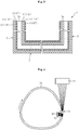
- FIG. 1 illustrates an annular structure 1 manufactured according to the present invention.
- the annular structure 1 is used as a ring frame for airplane bodies, and has a diameter of from approximately 3 m to 10 m.
- the annular structure 1 has a C-shape in cross section.
- the annular structure 1 is formed of a substantially flat plate-shaped web 2 and cylindrical flanges 3 provided substantially upright from a radially inner end and a radially outer end of the web 2.
- the cross-sectional shape of the annular structure 1 is somewhat different in parts in an annular direction.
- a short-side dimension L 2 of the web 2 and a short-side dimension L 3 of the flanges 3 are set to be somewhat larger for the purpose of enhancement of strength.
- the short-side dimension L 2 of the web 2 and the short-side dimension L 3 of the flanges 3 are set to be somewhat smaller for the purpose of weight reduction.
- the annular structure 1 is made of a composite material obtained by impregnating a dry preform formed of a plurality of laminated reinforcing fiber layers with a resin.
- the reinforcing fiber comprise carbon fiber and glass fiber.
- the resin comprise a thermosetting resin and a thermoplastic resin.
- the thermosetting resin comprises an epoxy resin, a bismaleimide resin, and a polyimide resin
- the thermoplastic resin comprises a polyether ether ketone resin.
- the annular structure 1 comprises a plurality of reinforcing fiber layers each formed of reinforcing fibers aligned in a predetermined direction.
- a first reinforcing fiber layer 11 formed of reinforcing fibers orientated in a direction in which the reinforcing fibers intersect with the annular direction at a predetermined angle (hereinafter, referred to as + ⁇ direction)
- a second reinforcing fiber layer 12 formed of reinforcing fibers orientated in a direction symmetrical to that of the reinforcing fibers of the first reinforcing fiber layer 11 with respect to the annular direction
- a third reinforcing fiber layer 13 formed of reinforcing fibers orientated in the annular direction (hereinafter, referred to as 0° direction).
- the first reinforcing fiber layer 11, the second reinforcing fiber layer 12, and the third reinforcing fiber layer 13 are laminated in a manner that the respective fiber orientation directions each intersect with that of adjacent one layer.
- the third reinforcing fiber layer 13 (0°), the first reinforcing fiber layer 11 (+ ⁇ ), and the second reinforcing fiber layer 12 (- ⁇ ) are repeatedly laminated in this order, the number of each of the three layers being, for example, five to ten.
- Each of the orientation angles ⁇ of the first reinforcing fiber layer 11 and the second reinforcing fiber layer 12 is set within a range of 20° to 70°, for example, set to 60°.
- the first reinforcing fiber layer 11, the second reinforcing fiber layer 12, and the third reinforcing fiber layer 13 are continuously provided along the web 2 and the pair of flanges 3.
- reinforcing fibers seamlessly continue from an end surface 3a of one of the flanges 3 to an end surface 3a of another of the flanges 3 and are orientated at a certain angle.
- the above-mentioned annular structure 1 is manufactured through a dry preform forming step, a separation step, and a resin impregnating step. In the following, those steps are sequentially described.
- the dry preform forming step refers to a step of forming a hollow annular dry preform by feeding reinforcing fibers to an outer periphery of an annular mandrel 20 as illustrated in FIG. 4 .
- the mandrel 20 has, for example, a rectangular shape in cross-section (square shape in this embodiment), and has an annular shape similar to that of the annular structure 1 illustrated in FIG. 1 .
- the mandrel 20 is formed into a hollow shape for the purpose of weight reduction.
- the cross-sectional shape of the annular structure 1 is somewhat different in parts in the annular direction.
- the cross-sectional shape of the mandrel 20 is also somewhat different in parts in the annular direction.
- a feeding apparatus for feeding reinforcing fibers to an outer peripheral surface of the mandrel 20 comprises a rotation drive portion (not shown) for rotating the mandrel 20 to one side in the annular direction (clockwise direction in FIG. 4 , refer to the arrow), an annular fiber-feeding portion 30 for feeding reinforcing fibers to the outer peripheral surface of the mandrel 20 along the annular direction, and a fiber winding portion 40 for winding the reinforcing fibers around the outer peripheral surface of the mandrel 20.
- a plurality of reinforcing fibers fed from the annular fiber-feeding portion 30 are arranged through intermediation of a guide 31 onto the outer peripheral surface of the mandrel 20.
- the guide 31 is provided with a plurality of guide holes (not shown) for guiding the reinforcing fibers.
- the reinforcing fibers are arranged onto the outer peripheral surface of the mandrel 20 under a state in which the reinforcing fibers are aligned in the annular direction.
- annular reinforcing fibers are arranged with a uniform density over the entire outer peripheral surface of the mandrel 20 having a rectangular shape in cross-section. In this way, the third reinforcing fiber layer 13 obtained by orientating the reinforcing fibers in the annular direction (0°) is fed on the outer peripheral surface of the mandrel 20.
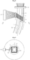
- a plurality of reinforcing fibers fed from the fiber winding portion 40 are wound around the outer peripheral surface of the mandrel 20 through intermediation of another guide 41 as illustrated in FIG. 5 .
- the guide 41 is provided with a plurality of guide holes (not shown) for guiding the reinforcing fibers.
- the guide holes are arrayed in the annular direction, and hence the plurality of reinforcing fibers guided by the guide holes are arrayed in the annular direction. In this way, a sheet-like fiber bundle A is formed. Then, as illustrated in FIG.
- both the fiber winding portion 40 and the guide 41 are revolved around the mandrel 20 so that the sheet-like fiber bundle A is wound around the outer periphery of the mandrel 20 (refer to FIG. 5 ) .
- the fiber winding portion 40 and the guide 41 are revolved while the mandrel 20 is rotated to the one side in the annular direction (refer to the arrow), there is fed a sheet-like fiber bundle A formed of the reinforcing fibers aligned parallel to each other at a predetermined angle (+ ⁇ ) with respect to an annular direction C.
- the fiber bundles A are laid around the outer periphery of the mandrel 20 without gaps.
- the cross-sectional shape of the mandrel 20 is different in parts in the annular direction, when the sheet-like fiber bundle A is wound around the mandrel 20, each of the reinforcing fibers of the sheet-like fiber bundle A conforms to an outer peripheral shape of the mandrel 20.
- the fiber bundle A as a whole can easily conform to the outer peripheral shape of the mandrel 20.
- the first reinforcing fiber layer 11 obtained by aligning the reinforcing fibers in a direction (+ ⁇ ) in which the reinforcing fibers intersect with the annular direction C is fed to the outer periphery of the mandrel 20.
- the third reinforcing fiber layer 13 is fixed to the outer periphery of the mandrel 20.
- the reinforcing fibers of the first reinforcing fiber layer are wound by an amount of one rotation of the mandrel 20 in the annular direction in accordance with the one rotation of the mandrel 20 in the annular direction, which is made by the rotation drive portion, the rotation drive portion, the fiber winding portion 40, and the guide 41 are stopped, and the reinforcing fibers fed from the fiber winding portion 40 and the reinforcing fibers in the annular direction are cut once.
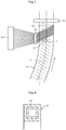
- the mandrel 20 is rotated by the rotation drive portion toward another side in the annular direction (counterclockwise direction in FIG. 7 , refer to the arrow) at the same speed as that in the above-mentioned case.
- the fiber winding portion 40 and the guide 41 are revolved in the same direction at the same speed as those in the above-mentioned case.
- the sheet-like fiber bundle A formed of reinforcing fibers aligned at a predetermined angle (- ⁇ ) with respect to the annular direction C is wound around the outer peripheral surface of the mandrel 20, with the result that the second reinforcing fiber layer 12 is laminated around an outer periphery of the first reinforcing fiber layer 11.
- the third reinforcing fiber layer 13, the first reinforcing fiber layer 11, and the second reinforcing fiber layer 12 are sequentially laminated (refer to FIG. 3 ).
- a hollow annular dry preform 50 is formed around the outer periphery of the mandrel 20 (refer to FIG. 8 ).
- a forming method for the second reinforcing fiber layer 12 is not limited to that described above.
- the second reinforcing fiber layer 12 may be formed by revolving the fiber winding portion 40 and the guide 41 into a direction reverse to the direction of the arrow in FIG. 6 (clockwise direction) while the mandrel 20 is rotated with the rotation drive portion toward the one side in the annular direction (in the same direction as that illustrated in FIG. 5 ).
- the dry preform 50 is temporarily fixed with binder or the like. Specifically, after the dry preform 50 is formed by mixing thermal adhesive binder fibers into the reinforcing fibers fed from the annular fiber-feeding portion 30 or the reinforcing fibers fed from the fiber winding portion 40, the dry preform 50 thus formed is heated so that the binder fibers are molten. When the binder fibers are solidified, the dry preform 50 can be temporarily fixed. Alternatively, temporal fixation may be performed by supplying adhesive powder-form or mist-form binder to a surface of the dry preform 50 after the dry preform 50 is formed. Note that, when necessary, end portions of the reinforcing fibers may be temporarily fixed to a surface of the mandrel 20 or a surface of the reinforcing fiber layer with binder or the like.
- the hollow annular dry preform 50 thus obtained is divided into a plurality of pieces (two in illustration) along the annular direction, and the mandrel 20 is taken out from the inside (separation step) .
- a pair of divided dry preforms 51 each having the same shape as that of the annular structure 1 illustrated in FIG. 1 , that is, a C-shape in cross-section formed of a web 52 and flanges 53.
- the divided dry preform 51 separated from the mandrel 20 is impregnated with a resin, and the resin is solidified. In this way, a composite material is formed.
- a method of impregnating and solidifying the resin is not particularly limited.
- the resin can be impregnated and solidified by a resin transfer molding (RTM) method. In this way, the annular structure 1 made of the composite material is completed (refer to FIG. 1 ).
- the present invention is not limited to the above-mentioned embodiment.
- other embodiments manufactured according to the invention are described. Portions having the same functions as those of the above-mentioned embodiment are denoted by the same reference symbols, and redundant description is omitted.
- the resin impregnating step is performed after the separation step, but reversely, after a hollow annular composite material is formed by impregnating a resin into the hollow annular dry preform 50 illustrated in FIG. 8 , the composite material thus formed may be divided along the annular direction so that mandrel 20 is taken out from the inside.
- the resin impregnating step and the dry preform forming step can be simultaneously performed.
- a resin is applied in advance by dipping or the like to the surfaces of reinforcing fibers fed from the annular fiber-feeding portion 30, and the reinforcing fibers is aligned in the annular direction and fed to the outer periphery of the mandrel 20.
- the resin adhering to the reinforcing fibers is impregnated into the dry preform 50.
- the annular structure 1 made of the composite material can be obtained by performing heating after that.
- the annular structure 1 has a C-shape in cross-section, but the present invention is not limited thereto.
- an annular structure 101 having an H-shape in cross-section as illustrated in FIG. 10 may be formed.
- the annular structure 1 is formed by impregnating a resin into the pair of divided dry preforms 51 each having a C-shape in cross-section, and then the pair of divided dry preforms 51 are fixed back-to-back to each other. In this way, the annular structure 101 having an H-shape in cross-section is obtained.
- the annular structure 101 having an H-shape in cross-section is obtained by impregnating a resin under a state in which the pair of divided dry preforms 51 each having a C-shape in cross-section are arranged back-to-back to each other.
- the hollow annular dry preform 50 is divided into two in the separation step, but the present invention is not limited thereto.
- the dry preform 50 may be divided into three.
- the dry preform 50 is divided into a cylindrical divided dry preform 61 and a pair of divided dry preforms 62 each having an L-shape in cross-section.
- Annular structures 261 and 262 are obtained by impregnating a resin into those divided dry preforms 61 and 62.
- Those annular structures 261 and 262 may be used independently of each other, or may form an annular structure 201 having an H-shape in cross-section by being combined and integrated with each other as illustrated in FIG. 12 .
- the fiber winding portion 40 feeds the sheet-like fiber bundle A formed of reinforcing fibers aligned in the annular direction, but the present invention is not limited thereto.
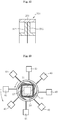
- the fiber winding portion 40 may comprise a plurality of (eight in the illustration) fiber winding portions 40 arranged at equal intervals along the outer periphery of the mandrel 20.
- the guide 41 is annularly provided so as to surround the outer periphery of the mandrel 20, and provided with guide holes at equal intervals.
- reinforcing fibers are wound around the outer periphery of the mandrel 20.
- the annular reinforcing fibers fed to the outer periphery of the mandrel 20 can be substantially simultaneously pressed with reinforcing fibers fed from the plurality of fiber winding portions 40 over the entire periphery.
- the mandrel 20 has a rectangular shape in cross-section, but the present invention is not limited thereto.
- the mandrel 20 may have a trapezoidal shape in cross-section or a circular shape in cross-section.
- first reinforcing fiber layer 11 and the second reinforcing fiber layer 12 orientated in respective inclined directions (+ ⁇ direction and - ⁇ direction) with respect to the annular direction
- third reinforcing fiber layer 13 orientated in the annular direction (0° direction) .
- the present invention is not limited thereto, and a combination of those layers may be appropriately changed in accordance with strength and a direction in which the strength is required.
- another reinforcing fiber layer inclined in another direction may be added to the first reinforcing fiber layer 11, the second reinforcing fiber layer 12, and the third reinforcing fiber layer 13.
- the annular structure 1 is used as a ring frame for airplane bodies, but the present invention is not limited thereto.
- the annular structure 1 may be used as a rim for bicycles and automobiles.
Landscapes
- Engineering & Computer Science (AREA)
- Mechanical Engineering (AREA)
- Physics & Mathematics (AREA)
- Nonlinear Science (AREA)
- Chemical & Material Sciences (AREA)
- Composite Materials (AREA)
- Aviation & Aerospace Engineering (AREA)
- Manufacturing & Machinery (AREA)
- Moulding By Coating Moulds (AREA)
- Reinforced Plastic Materials (AREA)
Description
- The present invention relates to a manufacturing method for a hollow annular dry preform.
- For example, an annular structure such as a ring frame for airplanes is required to be excellent in strength and lightweight, and hence, in some cases, made of a composite material formed of reinforcing fibers impregnated with a resin. However, the ring frame normally has a modified cross-sectional shape comprising bent portions, such as a C-shape or a T-shape, and it is difficult to form the ring frame having such a modified cross-sectional shape with the composite material.
- For example,
Patent Literature 1 discloses a method of forming an annular structure having an L-shape in cross-section with use of a dry preform made of braiding. Specifically, first, as illustrated inFIG. 14 , there is formed a long plate-shapeddry preform 105 having a tri-axial fabric structure formed of fibers (central strands) 105b orientated in a longitudinal direction and fibers (braiding strands) 105a orientated at braiding angles of ±α with respect to the longitudinal direction. Then, as illustrated inFIG. 15 , the long plate-shapeddry preform 105 is formed into an L-shape in cross-section formed of aflat plate portion 121 and aperpendicular portion 122 by being bent along a short-side intermediate portion. Then, theperpendicular portion 122 is directed inward, and thedry preform 105 is deformed into a circular arc shape. Next, as illustrated inFIG. 16 , a plurality of circular-arcdry preforms 105 are coupled to each other. In this way, an annulardry preform 102 having an L-shape in cross-section is formed. - However, in the dry preform made of the braiding as illustrated in
FIG. 14 , thebraiding strands 105a are crimped in a wave-like form, and hence strength in directions of the fibers is smaller than that of liner reinforcing fibers. Further, in order to crimp thebraiding strands 105a with thecentral strands 105b, it is necessary to array thecentral strands 105b while securing gaps. Thus, density of thecentral strands 105b decreases, which leads to a decrease in strength in the longitudinal direction. Further, a resin intrudes into the gaps between thecentral strands 105b, which leads to an increase in weight. In addition, the annulardry preform 102 is formed by coupling the plurality of circular-arc dry preforms 105 to each other, and hence reinforcing fibers are not continuous in an annular direction. As a result, strength in the annular direction decreases. - Meanwhile,
Patent Literature 2 discloses an annular structure formed of a plurality of fiber layers in each of which reinforcing fibers are orientated in a predetermined direction. Specifically, as illustrated inFIG. 17 , a sheet-like fabric laminate 209 is formed by laminating afiber layer 210 in a first fiber direction (+45°), afiber layer 211 in a second fiber direction (-45°), and anadditional layer 212 in a third fiber direction (0°). Thefabric laminate 209 is bent to form a blank having an L-shape in cross-section, and then the blank having an L-shape in cross-section is curved in an annular direction. In this way, the annular structure is formed. As described above, fibers are aligned in a certain direction in each of the fiber layers, and hence the fibers are linear. As a result, strength in directions of the fibers is higher than that of braiding in which fibers are crimped. Further, it is unnecessary to crimp the fibers, and hence fibers can be laid without securing gaps, with the result that density is enhanced. Thus, strength of the annular structure further increases. In addition, an amount of resin to intrude between the fibers is reduced, which leads to weight reduction of the annular structure. -
EP 0 172 098 A1 -
DE 10 2007 049 347 A1 describes a method to produce a preform made of textile semi-finished goods for an annular frame profile made of composite fiber material. The strip-like preformed fibers are wound on the frame profile which rotates around its central axis. Incisions to the fiber band in axial direction allow same to be folded on such segments of the frame profile which extend in radial direction to the rotation axis. -
US 2006/0048890 A1 discloses a method for producing an annular, fiber-reinforced composite structure. An annular flat-plate web and a flange perpendicular to the web are bonded together, and the resultant annular fiber preform is impregnated with a matrix resin. -
US 2010/0252182 A1 discloses a device for manufacturing a fiber composite component with at least one distributing device for placing at least bend-shaped material onto a surface of a tool mold or semi-finished product for manufacturing the fiber composite component. -
- Patent Literature 1:
JP 2006-69166 A - Patent Literature 2:
JP 2008-543670 A - However, the annular structure formed by the method disclosed in
Patent Literature 2 has a low degree of freedom in design. Specifically, the flat plate portion (base part) cannot be curved in an annular direction within a single plane when fibers are arranged in a third fiber direction (annular direction) . Thus, it is necessary to form the flat plate portion only with fiber layers in the first fiber direction and the second fiber direction (±45°), which may lead to a risk that strength in the annular direction in the flat plate portion is insufficient. Further, the sheet-like fabric laminate 209 formed by laminating the fiber layers each formed of aligned fibers (refer toFIG. 17 ) has a lower degree of freedom in orientation of the fibers than that of the dry preform 105 (refer toFIG. 14 ) formed of braiding. Thus, it is difficult to deform the sheet-like fabric laminate 209 into a desired shape. In particular, when a part of the annular structure is different in cross-sectional shape in the annular direction, it is significantly difficult to deform the sheet-like fabric laminate 209 into such a desired shape. Further, when the annular structure has a large diameter (for example, diameter of 5 m or larger) for use, for example, as a ring frame for airplane bodies, it is difficult to perform an operation of forming the annular structure by curving the sheet-like fabric laminate 209 as described above. The operation is facilitated when, for example, the annular structure is formed by coupling a plurality of circular-arc segments to each other. However, in this case, strength decreases in the annular direction as in the above-mentioned case. - It is an object of the present invention to provide a hollow annular dry preform which is excellent in strength, lightweight, easily formed, and designed with a higher degree of freedom, an annular structure made of a composite material using the dry preform, and a manufacturing method for the annular structure.
- In order to achieve the above-mentioned object, the present invention provides a manufacturing method according to
claim 1. - The dry preform has the following advantages. (1) The dry preform comprises the plurality of reinforcing fiber layers each formed of the reinforcing fibers aligned in parallel to each other, and hence strength is higher and weight is smaller than those of braiding in which reinforcing fibers are crimped. (2) The annular dry preform can be formed merely by winding the reinforcing fibers spirally around the annular mandrel. Thus, unlike the method disclosed in
Patent Literature 2 above, it is no longer necessary to perform an operation of bending the sheet-like fabric laminate, and hence the dry preform can be formed more easily. (3) The reinforcing fibers are made continuous in the annular direction by the amount of at least one rotation while being wound around the outer periphery of the annular mandrel. In this way, the dry preform can be formed continuously in the annular direction. Thus, strength is higher than that in the case where a plurality of circular-arc dry preforms are coupled to each other. (4) The reinforcing fibers are wound in conformity with an outer peripheral shape of the annular mandrel. Thus, even when the cross-sectional shape of the annular structure is different in parts in the annular direction, the dry preform can be shaped in conformity with the annular mandrel. - The above-mentioned dry preform is be provided with reinforcing fiber layers in arbitrary directions other than that of the first reinforcing fiber layer, and hence can be designed with a higher degree of freedom. A second reinforcing fiber layer is provided, formed of reinforcing fibers which are wound spirally around the outer periphery of the annular mandrel, continue in the annular direction by the amount of at least one rotation, and are aligned in a direction symmetrical to the direction of the reinforcing fibers of the first reinforcing fiber layer with respect to the annular direction. A third reinforcing fiber layer is provided, formed of reinforcing fibers which continue in the annular direction by the amount of at least one rotation and are aligned in the annular direction.
- With use of the above-mentioned dry preform, the annular structure made of the composite material can be easily obtained. Specifically, it is possible to obtain the annular structure made of the composite material comprising at least one of a plurality of divided dry preforms formed by dividing the above-mentioned hollow annular dry preform along the annular direction, and a resin impregnated into the at least one of the plurality of divided dry preforms. This annular structure can be used, for example, as a ring frame for airplanes.
- The dry preform as described above can be manufactured by a method as defined in claim1 and separating the dry preform from the annular mandrel by dividing the dry preform along the annular direction into a plurality of divided dry preforms; and impregnating a resin into the plurality of divided dry preforms.
- Alternatively, the dry preform as described above can be manufactured by a method as defined in claim1 and impregnating a resin into the dry preform so that a composite material is formed; and separating the composite material from the annular mandrel by dividing the composite material along the annular direction into a plurality of divided composite materials. In this case, the forming of the dry preform and the impregnating of the resin can be simultaneously performed by feeding reinforcing fibers to the outer periphery of the annular mandrel after a resin is applied to surfaces of the reinforcing fibers.
- When the first reinforcing fiber layer is formed by wounding a reinforcing fiber bundle, which is formed of a plurality of reinforcing fibers aligned in parallel to each other, around the outer periphery of the annular mandrel, the reinforcing fiber can be wound efficiently.
- Further, when the dry preform comprises a third reinforcing fiber layer formed of reinforcing fibers which continue in the annular direction by the amount of at least one rotation and are aligned in the annular direction, the third reinforcing fiber layer can be easily fixed to the outer periphery of the annular mandrel by feeding the reinforcing fibers aligned in the annular direction to the outer periphery of the mandrel and winding the reinforcing fibers of the first reinforcing fiber layer spirally around an outer periphery of the reinforcing fibers of the third reinforcing fiber layer.
- As described above, according to the present invention, it is possible to obtain the annular dry preform which is excellent in strength, lightweight, easily formed, and designed with a higher degree of freedom, an annular structure made of a composite material using the dry preform, and a manufacturing method for the annular structure.
-
- [
FIG. 1 ] A front view of an annular structure according to an embodiment of the present invention. - [
FIG. 2 ] A sectional view taken along the line X-X ofFIG. 1 . - [
FIG. 3 ] A sectional view illustrating a lamination state of reinforcing fiber layers of the annular structure. - [
FIG. 4 ] A front view illustrating a dry preform forming step in a manufacturing method for the annular structure, illustrating how a first reinforcing fiber layer and a third reinforcing fiber layer are fed. - [
FIG. 5 ] An enlarged view ofFIG. 4 . - [
FIG. 6 ] A sectional view taken along the line Y-Y ofFIG. 5 . - [
FIG. 7 ] Another front view illustrating the dry preform forming step in the manufacturing method for the annular structure, illustrating how a second reinforcing fiber layer is fed. - [
FIG. 8 ] A sectional view of a hollow annular dry preform and a hollow annular mandrel. - [
FIG. 9 ] A sectional view of a separation step in the manufacturing method for the annular structure. - [
FIG. 10 ] A sectional view of an annular structure according to another embodiment of the present invention. - [
FIG. 11 ] A sectional view illustrating a separation step in a manufacturing method according to still another embodiment of the present invention. - [
FIG. 12 ] A sectional view of an annular structure according to the still another embodiment. - [
FIG. 13 ] A front view illustrating a dry preform forming step in a manufacturing method according to yet another embodiment of the present invention, illustrating how reinforcing fibers of the first reinforcing fiber layer are wound. - [
FIG. 14 ] A perspective view of a long plate-shaped dry preform made of braiding (corresponding toFIG. 4 of Patent Literature 1) . - [
FIG. 15 ] A perspective view illustrating a state in which the long plate-shaped dry preform ofFIG. 14 is bent along a short-side intermediate portion (corresponding toFIG. 5 of Patent Literature 1) . - [
FIG. 16 ] A perspective view of an annular dry preform formed by coupling the dry preforms ofFIG. 15 (corresponding toFIG. 6 of Patent Literature 1). - [
FIG. 17 ] A plan view of a sheet-like fabric laminate (corresponding toFIG. 3 of Patent Literature 2). - In the following, description is made of embodiments manufactured according to the present invention with reference to the drawings.
-
FIG. 1 illustrates anannular structure 1 manufactured according to the present invention. Theannular structure 1 is used as a ring frame for airplane bodies, and has a diameter of from approximately 3 m to 10 m. As illustrated inFIG. 2 , theannular structure 1 has a C-shape in cross section. Specifically, theannular structure 1 is formed of a substantially flat plate-shapedweb 2 andcylindrical flanges 3 provided substantially upright from a radially inner end and a radially outer end of theweb 2. The cross-sectional shape of theannular structure 1 is somewhat different in parts in an annular direction. Specifically, although not shown in detail, at parts required to have especially high strength, a short-side dimension L2 of theweb 2 and a short-side dimension L3 of theflanges 3 are set to be somewhat larger for the purpose of enhancement of strength. Meanwhile, at parts required to have relatively low strength, the short-side dimension L2 of theweb 2 and the short-side dimension L3 of theflanges 3 are set to be somewhat smaller for the purpose of weight reduction. - The
annular structure 1 is made of a composite material obtained by impregnating a dry preform formed of a plurality of laminated reinforcing fiber layers with a resin. Examples of the reinforcing fiber comprise carbon fiber and glass fiber. Examples of the resin comprise a thermosetting resin and a thermoplastic resin. Specifically, the thermosetting resin comprises an epoxy resin, a bismaleimide resin, and a polyimide resin, and the thermoplastic resin comprises a polyether ether ketone resin. - As illustrated in
FIG. 3 , theannular structure 1 comprises a plurality of reinforcing fiber layers each formed of reinforcing fibers aligned in a predetermined direction. In the illustration, there are laminated a first reinforcingfiber layer 11 formed of reinforcing fibers orientated in a direction in which the reinforcing fibers intersect with the annular direction at a predetermined angle (hereinafter, referred to as +θ direction), a second reinforcingfiber layer 12 formed of reinforcing fibers orientated in a direction symmetrical to that of the reinforcing fibers of the first reinforcingfiber layer 11 with respect to the annular direction (hereinafter, referred to as -θ direction), and a third reinforcingfiber layer 13 formed of reinforcing fibers orientated in the annular direction (hereinafter, referred to as 0° direction). The first reinforcingfiber layer 11, the second reinforcingfiber layer 12, and the third reinforcingfiber layer 13 are laminated in a manner that the respective fiber orientation directions each intersect with that of adjacent one layer. In this embodiment, the third reinforcing fiber layer 13 (0°), the first reinforcing fiber layer 11 (+θ), and the second reinforcing fiber layer 12 (-θ) are repeatedly laminated in this order, the number of each of the three layers being, for example, five to ten. Each of the orientation angles θ of the first reinforcingfiber layer 11 and the second reinforcingfiber layer 12 is set within a range of 20° to 70°, for example, set to 60°. The first reinforcingfiber layer 11, the second reinforcingfiber layer 12, and the third reinforcingfiber layer 13 are continuously provided along theweb 2 and the pair offlanges 3. In particular, in each of the first reinforcingfiber layer 11 and the second reinforcingfiber layer 12, reinforcing fibers seamlessly continue from anend surface 3a of one of theflanges 3 to anend surface 3a of another of theflanges 3 and are orientated at a certain angle. - The above-mentioned
annular structure 1 is manufactured through a dry preform forming step, a separation step, and a resin impregnating step. In the following, those steps are sequentially described. - The dry preform forming step refers to a step of forming a hollow annular dry preform by feeding reinforcing fibers to an outer periphery of an
annular mandrel 20 as illustrated inFIG. 4 . Themandrel 20 has, for example, a rectangular shape in cross-section (square shape in this embodiment), and has an annular shape similar to that of theannular structure 1 illustrated inFIG. 1 . In the illustration, themandrel 20 is formed into a hollow shape for the purpose of weight reduction. As described above, the cross-sectional shape of theannular structure 1 is somewhat different in parts in the annular direction. Thus, in conformity therewith, the cross-sectional shape of themandrel 20 is also somewhat different in parts in the annular direction. - A feeding apparatus for feeding reinforcing fibers to an outer peripheral surface of the
mandrel 20 comprises a rotation drive portion (not shown) for rotating themandrel 20 to one side in the annular direction (clockwise direction inFIG. 4 , refer to the arrow), an annular fiber-feedingportion 30 for feeding reinforcing fibers to the outer peripheral surface of themandrel 20 along the annular direction, and afiber winding portion 40 for winding the reinforcing fibers around the outer peripheral surface of themandrel 20. - A plurality of reinforcing fibers fed from the annular fiber-feeding
portion 30 are arranged through intermediation of aguide 31 onto the outer peripheral surface of themandrel 20. Theguide 31 is provided with a plurality of guide holes (not shown) for guiding the reinforcing fibers. Through guiding of the reinforcing fibers with the guide holes, the reinforcing fibers are arranged onto the outer peripheral surface of themandrel 20 under a state in which the reinforcing fibers are aligned in the annular direction. In this embodiment, annular reinforcing fibers are arranged with a uniform density over the entire outer peripheral surface of themandrel 20 having a rectangular shape in cross-section. In this way, the third reinforcingfiber layer 13 obtained by orientating the reinforcing fibers in the annular direction (0°) is fed on the outer peripheral surface of themandrel 20. - Simultaneously, a plurality of reinforcing fibers fed from the
fiber winding portion 40 are wound around the outer peripheral surface of themandrel 20 through intermediation of anotherguide 41 as illustrated inFIG. 5 . Theguide 41 is provided with a plurality of guide holes (not shown) for guiding the reinforcing fibers. In this embodiment, the guide holes are arrayed in the annular direction, and hence the plurality of reinforcing fibers guided by the guide holes are arrayed in the annular direction. In this way, a sheet-like fiber bundle A is formed. Then, as illustrated inFIG. 6 , both thefiber winding portion 40 and theguide 41 are revolved around themandrel 20 so that the sheet-like fiber bundle A is wound around the outer periphery of the mandrel 20 (refer toFIG. 5 ) . In this case, when thefiber winding portion 40 and theguide 41 are revolved while themandrel 20 is rotated to the one side in the annular direction (refer to the arrow), there is fed a sheet-like fiber bundle A formed of the reinforcing fibers aligned parallel to each other at a predetermined angle (+θ) with respect to an annular direction C. Further, when themandrel 20 is rotated to the one side in the annular direction by an amount of a width W of the sheet-like fiber bundle A during one revolution of thefiber winding portion 40 and theguide 41 around themandrel 20, the fiber bundles A are laid around the outer periphery of themandrel 20 without gaps. Note that, although the cross-sectional shape of themandrel 20 is different in parts in the annular direction, when the sheet-like fiber bundle A is wound around themandrel 20, each of the reinforcing fibers of the sheet-like fiber bundle A conforms to an outer peripheral shape of themandrel 20. Thus, the fiber bundle A as a whole can easily conform to the outer peripheral shape of themandrel 20. In this way, the first reinforcingfiber layer 11 obtained by aligning the reinforcing fibers in a direction (+θ) in which the reinforcing fibers intersect with the annular direction C is fed to the outer periphery of themandrel 20. Through winding of the fiber bundle A around an outer periphery of the third reinforcingfiber layer 13 fed from the annular fiber-feedingportion 30 through intermediation of theguide 31 onto the outer peripheral surface of themandrel 20 as described above, the third reinforcingfiber layer 13 is fixed to the outer periphery of themandrel 20. - After the reinforcing fibers of the first reinforcing fiber layer are wound by an amount of one rotation of the
mandrel 20 in the annular direction in accordance with the one rotation of themandrel 20 in the annular direction, which is made by the rotation drive portion, the rotation drive portion, thefiber winding portion 40, and theguide 41 are stopped, and the reinforcing fibers fed from thefiber winding portion 40 and the reinforcing fibers in the annular direction are cut once. Then, as illustrated inFIG. 7 , themandrel 20 is rotated by the rotation drive portion toward another side in the annular direction (counterclockwise direction inFIG. 7 , refer to the arrow) at the same speed as that in the above-mentioned case. Simultaneously, thefiber winding portion 40 and theguide 41 are revolved in the same direction at the same speed as those in the above-mentioned case. In this way, the sheet-like fiber bundle A formed of reinforcing fibers aligned at a predetermined angle (-θ) with respect to the annular direction C is wound around the outer peripheral surface of themandrel 20, with the result that the second reinforcingfiber layer 12 is laminated around an outer periphery of the first reinforcingfiber layer 11. Through repetition of the above-mentioned steps, the third reinforcingfiber layer 13, the first reinforcingfiber layer 11, and the second reinforcingfiber layer 12 are sequentially laminated (refer toFIG. 3 ). In this way, a hollow annulardry preform 50 is formed around the outer periphery of the mandrel 20 (refer toFIG. 8 ). Note that, a forming method for the second reinforcingfiber layer 12 is not limited to that described above. For example, the second reinforcingfiber layer 12 may be formed by revolving thefiber winding portion 40 and theguide 41 into a direction reverse to the direction of the arrow inFIG. 6 (clockwise direction) while themandrel 20 is rotated with the rotation drive portion toward the one side in the annular direction (in the same direction as that illustrated inFIG. 5 ). - The
dry preform 50 is temporarily fixed with binder or the like. Specifically, after thedry preform 50 is formed by mixing thermal adhesive binder fibers into the reinforcing fibers fed from the annular fiber-feedingportion 30 or the reinforcing fibers fed from thefiber winding portion 40, thedry preform 50 thus formed is heated so that the binder fibers are molten. When the binder fibers are solidified, thedry preform 50 can be temporarily fixed. Alternatively, temporal fixation may be performed by supplying adhesive powder-form or mist-form binder to a surface of thedry preform 50 after thedry preform 50 is formed. Note that, when necessary, end portions of the reinforcing fibers may be temporarily fixed to a surface of themandrel 20 or a surface of the reinforcing fiber layer with binder or the like. - As illustrated in
FIG. 9 , the hollow annulardry preform 50 thus obtained is divided into a plurality of pieces (two in illustration) along the annular direction, and themandrel 20 is taken out from the inside (separation step) . With this, there are obtained a pair of divideddry preforms 51 each having the same shape as that of theannular structure 1 illustrated inFIG. 1 , that is, a C-shape in cross-section formed of aweb 52 andflanges 53. In this case, it is preferred to arrange end portions of the reinforcing fibers of the first reinforcingfiber layer 11 and the second reinforcingfiber layer 12 on divided surfaces of the hollow annulardry preform 50 because seams of the reinforcing fibers are not formed at all in the first reinforcingfiber layer 11 and the second reinforcingfiber layer 12 of theweb 52 or theflanges 53 of each of the divideddry preforms 51. - In the resin impregnating step, the divided
dry preform 51 separated from themandrel 20 is impregnated with a resin, and the resin is solidified. In this way, a composite material is formed. A method of impregnating and solidifying the resin is not particularly limited. For example, the resin can be impregnated and solidified by a resin transfer molding (RTM) method. In this way, theannular structure 1 made of the composite material is completed (refer toFIG. 1 ). - The present invention is not limited to the above-mentioned embodiment. Hereinafter, other embodiments manufactured according to the invention are described. Portions having the same functions as those of the above-mentioned embodiment are denoted by the same reference symbols, and redundant description is omitted.
- In the above-mentioned embodiment, the resin impregnating step is performed after the separation step, but reversely, after a hollow annular composite material is formed by impregnating a resin into the hollow annular
dry preform 50 illustrated inFIG. 8 , the composite material thus formed may be divided along the annular direction so thatmandrel 20 is taken out from the inside. In this case, the resin impregnating step and the dry preform forming step can be simultaneously performed. For example, a resin is applied in advance by dipping or the like to the surfaces of reinforcing fibers fed from the annular fiber-feedingportion 30, and the reinforcing fibers is aligned in the annular direction and fed to the outer periphery of themandrel 20. By feeding the reinforcing fibers in the annular direction to the outer periphery of themandrel 20, the resin adhering to the reinforcing fibers is impregnated into thedry preform 50. And, theannular structure 1 made of the composite material can be obtained by performing heating after that. - Further, in the above-mentioned embodiment, the
annular structure 1 has a C-shape in cross-section, but the present invention is not limited thereto. For example, anannular structure 101 having an H-shape in cross-section as illustrated inFIG. 10 may be formed. In this case, theannular structure 1 is formed by impregnating a resin into the pair of divideddry preforms 51 each having a C-shape in cross-section, and then the pair of divideddry preforms 51 are fixed back-to-back to each other. In this way, theannular structure 101 having an H-shape in cross-section is obtained. Alternatively, theannular structure 101 having an H-shape in cross-section is obtained by impregnating a resin under a state in which the pair of divideddry preforms 51 each having a C-shape in cross-section are arranged back-to-back to each other. - Still further, in the above-mentioned embodiment, the hollow annular
dry preform 50 is divided into two in the separation step, but the present invention is not limited thereto. For example, as illustrated inFIG. 11 , thedry preform 50 may be divided into three. In the illustration, thedry preform 50 is divided into a cylindrical divideddry preform 61 and a pair of divideddry preforms 62 each having an L-shape in cross-section.Annular structures dry preforms annular structures annular structure 201 having an H-shape in cross-section by being combined and integrated with each other as illustrated inFIG. 12 . - Yet further, in the above-mentioned embodiment, the
fiber winding portion 40 feeds the sheet-like fiber bundle A formed of reinforcing fibers aligned in the annular direction, but the present invention is not limited thereto. For example, as illustrated inFIG. 13 , thefiber winding portion 40 may comprise a plurality of (eight in the illustration)fiber winding portions 40 arranged at equal intervals along the outer periphery of themandrel 20. Theguide 41 is annularly provided so as to surround the outer periphery of themandrel 20, and provided with guide holes at equal intervals. By revolving the plurality offiber winding portions 40 and theguide 41 together in directions indicated by the arrows, reinforcing fibers are wound around the outer periphery of themandrel 20. In this case, the annular reinforcing fibers fed to the outer periphery of the mandrel 20 (third reinforcing fiber layer 13) can be substantially simultaneously pressed with reinforcing fibers fed from the plurality offiber winding portions 40 over the entire periphery. - Yet further, in the above-mentioned embodiment, the
mandrel 20 has a rectangular shape in cross-section, but the present invention is not limited thereto. For example, themandrel 20 may have a trapezoidal shape in cross-section or a circular shape in cross-section. - Yet further, in the above-mentioned embodiment, there are provided the first reinforcing
fiber layer 11 and the second reinforcingfiber layer 12 orientated in respective inclined directions (+θ direction and -θ direction) with respect to the annular direction, and the third reinforcingfiber layer 13 orientated in the annular direction (0° direction) . However, the present invention is not limited thereto, and a combination of those layers may be appropriately changed in accordance with strength and a direction in which the strength is required. For example, another reinforcing fiber layer inclined in another direction may be added to the first reinforcingfiber layer 11, the second reinforcingfiber layer 12, and the third reinforcingfiber layer 13. - Yet further, in the above-mentioned embodiment, the
annular structure 1 is used as a ring frame for airplane bodies, but the present invention is not limited thereto. For example, theannular structure 1 may be used as a rim for bicycles and automobiles. -
- 1
- annular structure
- 2
- web
- 3
- flange
- 11
- first reinforcing fiber layer
- 12
- second reinforcing fiber layer
- 13
- third reinforcing fiber layer
- 20
- mandrel
- 30
- annular fiber-feeding portion
- 31
- guide
- 40
- fiber winding portion
- 41
- guide
- 50
- dry preform
- A
- sheet-like fiber bundle
Claims (6)
- A manufacturing method for a hollow annular dry preform (50) arranged on an outer periphery of an annular mandrel (20), the dry preform (50) comprising a plurality of reinforcing fiber layers (13, 11, 12) each formed of reinforcing fibers aligned in a predetermined direction intersecting with that of an adjacent layer,
the manufacturing method comprising:arranging a third reinforcing fiber layer (13) formed of reinforcing fibers, which continue in an annular direction by the amount of at least one rotation and are aligned in the annular direction, on the outer peripheral surface of an annular mandrel (20), the fibres of the third reinforcing fiber layer (13) being fed from an annular fiber-feeding portion (30) and begin arranged through intermediation of a guide (31) provided with a plurality of guide holes onto the outer peripheral surface of the mandrel (20);arranging a first reinforcing fiber layer (11) by winding reinforcing fibers formed as a sheet-like reinforcing fiber-bundle (A) spirally around an outer periphery of the annular mandrel (20), the reinforcing fibers of the first reinforcing fiber layer (11) seamlessly continuing in the annular direction by an amount of at least one rotation, and being aligned in a direction in which the reinforcing fibers intersect at a predetermined angle (+θ) with respect to the annular direction; andarranging a second reinforcing fiber layer (12) by winding reinforcing fibers formed as the sheet-like reinforcing fiber-bundle (A) spirally around the outer periphery of the annular mandrel (20), the reinforcing fibers of the second reinforcing fiber layer (12) seamlessly continuing in the annular direction by an amount of at least one rotation, and being aligned in a direction in which the reinforcing fibers intersect at a predetermined angle (-θ) with respect to the annular direction,the fibres of the first reinforcing fiber layer (11) and the second reinforcing fiber layer (12) being fed from a fiber winding portion (40) and being wound around the outer peripheral surface of the mandrel (20) through intermediation of a guide (41) provided with a plurality of guide holes,wherein each of the orientation angles (θ) of the first reinforcing fiber layer (11) and the second reinforcing fiber layer (12) is set within a range of 20° to 70°,wherein the guide holes of the guide (41) are arrayed in the annular direction, and hence the plurality of reinforcing fibers guided by the guide holes are arrayed in the annular direction so that the sheet-like fiber bundle (A) is formed, andwherein the fiber winding portion (40) and the guide (41) are revolved around the mandrel (20) so that the sheet-like fiber bundle (A) is wound around the outer periphery of the mandrel (20). - A manufacturing method according to claim 1, comprising:forming a dry preform by a manufacturing method according to claim 1;separating the dry preform from the annular mandrel by dividing the dry preform along an annular direction into a plurality of divided dry preforms; andimpregnating a resin into the plurality of divided dry preforms.
- A manufacturing method according to claim 1, comprising:forming a dry preform by a manufacturing method according to claim 1;impregnating a resin into the dry preform so that a composite material is formed; andseparating the composite material from the annular mandrel by dividing the composite material along the annular direction into a plurality of divided composite materials.
- A manufacturing method according to claim 1, wherein the forming of the dry preform and impregnating of the resin are simultaneously performed by feeding reinforcing fibers to the outer periphery of the annular mandrel after a resin is applied to surfaces of the reinforcing fibers.
- A manufacturing method according to claim 1, wherein the reinforcing fibers of the sheet-like reinforcing fiber bundle (A) are aligned in parallel to each other by the guide holes of guide (41), the guide holes being arrayed in the annular direction.
- A manufacturing method according to claim 1, wherein when the mandrel (20) is rotated to one side in the annular direction (C) by an amount of a width (W) of the sheet-like reinforcing fiber bundle (A) during one revolution of a fiber winding portion (40) and the guide (41) around the mandrel (20), the reinforcing fibers of the sheet-like reinforcing fiber bundle (A) are laid around the outer periphery of the mandrel (20) without gaps.
Applications Claiming Priority (1)
| Application Number | Priority Date | Filing Date | Title |
|---|---|---|---|
| JP2011067990A JP5697506B2 (en) | 2011-03-25 | 2011-03-25 | Dry preform, annular structure made of composite material, and manufacturing method thereof |
Publications (3)
| Publication Number | Publication Date |
|---|---|
| EP2502733A2 EP2502733A2 (en) | 2012-09-26 |
| EP2502733A3 EP2502733A3 (en) | 2014-03-12 |
| EP2502733B1 true EP2502733B1 (en) | 2020-10-21 |
Family
ID=45999748
Family Applications (1)
| Application Number | Title | Priority Date | Filing Date |
|---|---|---|---|
| EP12401045.5A Not-in-force EP2502733B1 (en) | 2011-03-25 | 2012-03-22 | Dry preform, annular structure made of a composite material, and manufacturing method for the annular structure |
Country Status (5)
| Country | Link |
|---|---|
| US (1) | US9481442B2 (en) |
| EP (1) | EP2502733B1 (en) |
| JP (1) | JP5697506B2 (en) |
| CN (1) | CN102689444B (en) |
| ES (1) | ES2855399T3 (en) |
Families Citing this family (13)
| Publication number | Priority date | Publication date | Assignee | Title |
|---|---|---|---|---|
| DE102012004942B4 (en) * | 2012-03-12 | 2014-02-20 | Munich Composites Gmbh | Process for producing a preform and a fiber composite prefabricated component produced therefrom |
| DE102013007609A1 (en) * | 2013-05-03 | 2014-11-06 | Audi Ag | Process for producing a fiber-reinforced plastic component |
| JP6266293B2 (en) * | 2013-10-09 | 2018-01-24 | 三菱重工業株式会社 | Pressure vessel and method for manufacturing the same |
| JP6223108B2 (en) * | 2013-10-09 | 2017-11-01 | 三菱重工業株式会社 | Pressure vessel and method for manufacturing the same |
| US10006156B2 (en) | 2014-03-21 | 2018-06-26 | Goodrich Corporation | Systems and methods for calculated tow fiber angle |
| FR3034337B1 (en) * | 2015-04-03 | 2017-05-19 | Plastic Omnium Cie | METHOD FOR MANUFACTURING AN INSERT OF AN OPENING OF A MOTOR VEHICLE |
| TWI623446B (en) * | 2015-07-10 | 2018-05-11 | 瑩信工業股份有限公司 | Manufacturing system of wheel supporting structure |
| JP2017066022A (en) * | 2015-09-29 | 2017-04-06 | Toto株式会社 | Dredged and ceramic plates |
| CN106956472B (en) * | 2017-03-03 | 2019-10-22 | 航天材料及工艺研究所 | Composite impact-resistant structure and forming method thereof |
| US11407253B2 (en) * | 2017-12-13 | 2022-08-09 | Falcon Composites Corp. | Bicycle rims and method of manufacture thereof |
| CN109927479A (en) * | 2017-12-15 | 2019-06-25 | 林书伟 | Vehicle wheel rim and its manufacturing method |
| JP7193282B2 (en) * | 2018-09-14 | 2022-12-20 | 株式会社Subaru | Preform shaping method and composite material molding method |
| JP7078905B2 (en) * | 2019-01-16 | 2022-06-01 | トヨタ自動車株式会社 | Manufacturing method of high pressure tank |
Citations (2)
| Publication number | Priority date | Publication date | Assignee | Title |
|---|---|---|---|---|
| EP1342554A1 (en) * | 2002-03-08 | 2003-09-10 | Airbus Deutschland GmbH | Method for making textile preforms from textile half-products |
| US20050235471A1 (en) * | 2004-04-23 | 2005-10-27 | Vincent Delecroix | Method of fabricating a helical two-dimensional fiber sheet |
Family Cites Families (12)
| Publication number | Priority date | Publication date | Assignee | Title |
|---|---|---|---|---|
| JPS50151273A (en) * | 1974-05-28 | 1975-12-04 | ||
| JPS6021531B2 (en) | 1978-06-06 | 1985-05-28 | 東レ株式会社 | Method for manufacturing curved fiber reinforced resin laminates |
| FR2568818B1 (en) * | 1984-08-10 | 1986-10-24 | Commissariat Energie Atomique | METHOD FOR MANUFACTURING A COMPOSITE MATERIAL, ARM OF ORTHOGONAL FIBERS, OF ANNULAR FORM AND WINDING APPARATUS FOR IMPLEMENTING THE METHOD |
| FR2630422B1 (en) * | 1988-04-25 | 1990-08-10 | Aerospatiale | DEVICE FOR APPLYING A FILAMENTARY WINDING ON ANY FORMED SUPPORT AND UNIVERSAL WINDING MACHINE INCLUDING APPLICATION |
| JPH09314687A (en) * | 1996-05-23 | 1997-12-09 | Toray Ind Inc | FRP cylinder |
| JP4309748B2 (en) * | 2003-11-25 | 2009-08-05 | シキボウ株式会社 | Dry preform for FRP window frames used in aircraft |
| JP2006056022A (en) * | 2004-08-17 | 2006-03-02 | Murata Mach Ltd | Manufacturing method of reinforcing fiber preform for curved FRP girders |
| JP4522796B2 (en) | 2004-09-06 | 2010-08-11 | 本田技研工業株式会社 | Manufacturing method of fiber reinforced composite material annular structure and annular frame for aircraft fuselage comprising the structure |
| DE102005028765B4 (en) | 2005-06-22 | 2016-01-21 | Airbus Operations Gmbh | Method for producing a reinforcing profile |
| DE102007049347B8 (en) * | 2007-10-12 | 2011-02-03 | Eads Deutschland Gmbh | Method for producing a preform from semifinished product, for producing an annular frame profile, use of the method and frame profile |
| DE102007054645A1 (en) | 2007-11-15 | 2009-05-28 | Airbus Deutschland Gmbh | Apparatus and method for producing a fiber composite component |
| JP2011037001A (en) * | 2007-12-14 | 2011-02-24 | Nippon Zeon Co Ltd | Frp pipe |
-
2011
- 2011-03-25 JP JP2011067990A patent/JP5697506B2/en not_active Expired - Fee Related
-
2012
- 2012-03-15 CN CN201210069385.8A patent/CN102689444B/en not_active Expired - Fee Related
- 2012-03-21 US US13/425,559 patent/US9481442B2/en not_active Expired - Fee Related
- 2012-03-22 ES ES12401045T patent/ES2855399T3/en active Active
- 2012-03-22 EP EP12401045.5A patent/EP2502733B1/en not_active Not-in-force
Patent Citations (2)
| Publication number | Priority date | Publication date | Assignee | Title |
|---|---|---|---|---|
| EP1342554A1 (en) * | 2002-03-08 | 2003-09-10 | Airbus Deutschland GmbH | Method for making textile preforms from textile half-products |
| US20050235471A1 (en) * | 2004-04-23 | 2005-10-27 | Vincent Delecroix | Method of fabricating a helical two-dimensional fiber sheet |
Also Published As
| Publication number | Publication date |
|---|---|
| ES2855399T3 (en) | 2021-09-23 |
| US9481442B2 (en) | 2016-11-01 |
| CN102689444B (en) | 2015-10-07 |
| EP2502733A3 (en) | 2014-03-12 |
| JP5697506B2 (en) | 2015-04-08 |
| US20120244302A1 (en) | 2012-09-27 |
| EP2502733A2 (en) | 2012-09-26 |
| CN102689444A (en) | 2012-09-26 |
| JP2012201002A (en) | 2012-10-22 |
Similar Documents
| Publication | Publication Date | Title |
|---|---|---|
| US9481442B2 (en) | Dry preform, annular structure made of a composite material, and manufacturing method for the annular structure | |
| EP2394909B1 (en) | Composite barrel sections for aircraft fuselages and methods for manufacturing such barrel sections | |
| EP2206597B1 (en) | Method and apparatus for manufacturing composite spars | |
| JP5429599B2 (en) | Curved reinforced fiber laminate, preform, and method for producing fiber reinforced resin composite material | |
| EP2532507B1 (en) | Filament winding method | |
| JP5014760B2 (en) | Fiber composite parts manufactured using braiding | |
| US8771450B2 (en) | Method for manufacturing a composite body and a composite body manufacturing arrangement | |
| US9776704B1 (en) | Composite pressure bulkhead | |
| US9181642B2 (en) | Triaxial textile armature, process for producing triaxial textile armatures and composite material part | |
| US11167520B2 (en) | Composite core with non-traditional geometries | |
| EP2535169B1 (en) | Method for producing structural material, and structural material | |
| EP3075524B1 (en) | Pressure bulkhead and method for producing a pressure bulkhead | |
| KR101376747B1 (en) | Fabricating parts with composite material reinforcement having a single crossing line | |
| US20110311782A1 (en) | Planar component of an aircraft and method for producing the same | |
| EP2913178B1 (en) | Cylindrical case and method for manufacturing cylindrical case | |
| US10974484B2 (en) | Forming method of cylindrical composite material, inner surface layering device, and cylindrical composite material | |
| US9909645B2 (en) | Flywheels for energy storage and methods of manufacture thereof | |
| EP3966022B1 (en) | Fibre-reinforced composite tubular shafts and method of manufacturing thereof | |
| US9919480B2 (en) | Method and device for producing a textile preform | |
| EP3308947A1 (en) | Blade component | |
| CN120840850A (en) | Preform of aircraft bulkhead and method for manufacturing the same | |
| HK1159040B (en) | Composite barrel sections for aircraft fuselages and methods for manufacturing such barrel sections | |
| HK1163032B (en) | Method for manufacturing composite barrel sections for aircraft fuselages |
Legal Events
| Date | Code | Title | Description |
|---|---|---|---|
| PUAI | Public reference made under article 153(3) epc to a published international application that has entered the european phase |
Free format text: ORIGINAL CODE: 0009012 |
|
| AK | Designated contracting states |
Kind code of ref document: A2 Designated state(s): AL AT BE BG CH CY CZ DE DK EE ES FI FR GB GR HR HU IE IS IT LI LT LU LV MC MK MT NL NO PL PT RO RS SE SI SK SM TR |
|
| AX | Request for extension of the european patent |
Extension state: BA ME |
|
| PUAL | Search report despatched |
Free format text: ORIGINAL CODE: 0009013 |
|
| AK | Designated contracting states |
Kind code of ref document: A3 Designated state(s): AL AT BE BG CH CY CZ DE DK EE ES FI FR GB GR HR HU IE IS IT LI LT LU LV MC MK MT NL NO PL PT RO RS SE SI SK SM TR |
|
| AX | Request for extension of the european patent |
Extension state: BA ME |
|
| RIC1 | Information provided on ipc code assigned before grant |
Ipc: B29C 53/58 20060101ALI20140206BHEP Ipc: B64C 1/06 20060101ALI20140206BHEP Ipc: B29B 11/16 20060101ALN20140206BHEP Ipc: B29C 70/32 20060101ALI20140206BHEP Ipc: B29C 70/20 20060101AFI20140206BHEP Ipc: B29C 70/54 20060101ALN20140206BHEP |
|
| 17P | Request for examination filed |
Effective date: 20140912 |
|
| RBV | Designated contracting states (corrected) |
Designated state(s): AL AT BE BG CH CY CZ DE DK EE ES FI FR GB GR HR HU IE IS IT LI LT LU LV MC MK MT NL NO PL PT RO RS SE SI SK SM TR |
|
| 17Q | First examination report despatched |
Effective date: 20150324 |
|
| STAA | Information on the status of an ep patent application or granted ep patent |
Free format text: STATUS: EXAMINATION IS IN PROGRESS |
|
| RIC1 | Information provided on ipc code assigned before grant |
Ipc: B29C 70/20 20060101AFI20190121BHEP Ipc: B64C 1/00 20060101ALN20190121BHEP Ipc: B29C 70/54 20060101ALN20190121BHEP Ipc: B29C 53/58 20060101ALI20190121BHEP Ipc: B29C 70/32 20060101ALI20190121BHEP Ipc: B64C 1/06 20060101ALI20190121BHEP Ipc: B29B 11/16 20060101ALN20190121BHEP |
|
| GRAP | Despatch of communication of intention to grant a patent |
Free format text: ORIGINAL CODE: EPIDOSNIGR1 |
|
| STAA | Information on the status of an ep patent application or granted ep patent |
Free format text: STATUS: GRANT OF PATENT IS INTENDED |
|
| RIC1 | Information provided on ipc code assigned before grant |
Ipc: B29C 70/54 20060101ALN20200512BHEP Ipc: B64C 1/00 20060101ALN20200512BHEP Ipc: B64C 1/06 20060101ALI20200512BHEP Ipc: B29C 53/58 20060101ALI20200512BHEP Ipc: B29C 70/32 20060101ALI20200512BHEP Ipc: B29B 11/16 20060101ALN20200512BHEP Ipc: B29C 70/20 20060101AFI20200512BHEP |
|
| INTG | Intention to grant announced |
Effective date: 20200528 |
|
| GRAS | Grant fee paid |
Free format text: ORIGINAL CODE: EPIDOSNIGR3 |
|
| GRAA | (expected) grant |
Free format text: ORIGINAL CODE: 0009210 |
|
| STAA | Information on the status of an ep patent application or granted ep patent |
Free format text: STATUS: THE PATENT HAS BEEN GRANTED |
|
| AK | Designated contracting states |
Kind code of ref document: B1 Designated state(s): AL AT BE BG CH CY CZ DE DK EE ES FI FR GB GR HR HU IE IS IT LI LT LU LV MC MK MT NL NO PL PT RO RS SE SI SK SM TR |
|
| REG | Reference to a national code |
Ref country code: GB Ref legal event code: FG4D |
|
| REG | Reference to a national code |
Ref country code: CH Ref legal event code: EP |
|
| REG | Reference to a national code |
Ref country code: IE Ref legal event code: FG4D |
|
| REG | Reference to a national code |
Ref country code: DE Ref legal event code: R096 Ref document number: 602012072869 Country of ref document: DE |
|
| REG | Reference to a national code |
Ref country code: AT Ref legal event code: REF Ref document number: 1325411 Country of ref document: AT Kind code of ref document: T Effective date: 20201115 |
|
| REG | Reference to a national code |
Ref country code: AT Ref legal event code: MK05 Ref document number: 1325411 Country of ref document: AT Kind code of ref document: T Effective date: 20201021 |
|
| REG | Reference to a national code |
Ref country code: NL Ref legal event code: MP Effective date: 20201021 |
|
| PG25 | Lapsed in a contracting state [announced via postgrant information from national office to epo] |
Ref country code: NO Free format text: LAPSE BECAUSE OF FAILURE TO SUBMIT A TRANSLATION OF THE DESCRIPTION OR TO PAY THE FEE WITHIN THE PRESCRIBED TIME-LIMIT Effective date: 20210121 Ref country code: PT Free format text: LAPSE BECAUSE OF FAILURE TO SUBMIT A TRANSLATION OF THE DESCRIPTION OR TO PAY THE FEE WITHIN THE PRESCRIBED TIME-LIMIT Effective date: 20210222 Ref country code: NL Free format text: LAPSE BECAUSE OF FAILURE TO SUBMIT A TRANSLATION OF THE DESCRIPTION OR TO PAY THE FEE WITHIN THE PRESCRIBED TIME-LIMIT Effective date: 20201021 Ref country code: RS Free format text: LAPSE BECAUSE OF FAILURE TO SUBMIT A TRANSLATION OF THE DESCRIPTION OR TO PAY THE FEE WITHIN THE PRESCRIBED TIME-LIMIT Effective date: 20201021 Ref country code: FI Free format text: LAPSE BECAUSE OF FAILURE TO SUBMIT A TRANSLATION OF THE DESCRIPTION OR TO PAY THE FEE WITHIN THE PRESCRIBED TIME-LIMIT Effective date: 20201021 Ref country code: GR Free format text: LAPSE BECAUSE OF FAILURE TO SUBMIT A TRANSLATION OF THE DESCRIPTION OR TO PAY THE FEE WITHIN THE PRESCRIBED TIME-LIMIT Effective date: 20210122 |
|
| REG | Reference to a national code |
Ref country code: LT Ref legal event code: MG4D |
|
| PG25 | Lapsed in a contracting state [announced via postgrant information from national office to epo] |
Ref country code: BG Free format text: LAPSE BECAUSE OF FAILURE TO SUBMIT A TRANSLATION OF THE DESCRIPTION OR TO PAY THE FEE WITHIN THE PRESCRIBED TIME-LIMIT Effective date: 20210121 Ref country code: AT Free format text: LAPSE BECAUSE OF FAILURE TO SUBMIT A TRANSLATION OF THE DESCRIPTION OR TO PAY THE FEE WITHIN THE PRESCRIBED TIME-LIMIT Effective date: 20201021 Ref country code: SE Free format text: LAPSE BECAUSE OF FAILURE TO SUBMIT A TRANSLATION OF THE DESCRIPTION OR TO PAY THE FEE WITHIN THE PRESCRIBED TIME-LIMIT Effective date: 20201021 Ref country code: PL Free format text: LAPSE BECAUSE OF FAILURE TO SUBMIT A TRANSLATION OF THE DESCRIPTION OR TO PAY THE FEE WITHIN THE PRESCRIBED TIME-LIMIT Effective date: 20201021 Ref country code: LV Free format text: LAPSE BECAUSE OF FAILURE TO SUBMIT A TRANSLATION OF THE DESCRIPTION OR TO PAY THE FEE WITHIN THE PRESCRIBED TIME-LIMIT Effective date: 20201021 Ref country code: IS Free format text: LAPSE BECAUSE OF FAILURE TO SUBMIT A TRANSLATION OF THE DESCRIPTION OR TO PAY THE FEE WITHIN THE PRESCRIBED TIME-LIMIT Effective date: 20210221 |
|
| PG25 | Lapsed in a contracting state [announced via postgrant information from national office to epo] |
Ref country code: HR Free format text: LAPSE BECAUSE OF FAILURE TO SUBMIT A TRANSLATION OF THE DESCRIPTION OR TO PAY THE FEE WITHIN THE PRESCRIBED TIME-LIMIT Effective date: 20201021 |
|
| REG | Reference to a national code |
Ref country code: DE Ref legal event code: R097 Ref document number: 602012072869 Country of ref document: DE |
|
| PG25 | Lapsed in a contracting state [announced via postgrant information from national office to epo] |
Ref country code: LT Free format text: LAPSE BECAUSE OF FAILURE TO SUBMIT A TRANSLATION OF THE DESCRIPTION OR TO PAY THE FEE WITHIN THE PRESCRIBED TIME-LIMIT Effective date: 20201021 Ref country code: SK Free format text: LAPSE BECAUSE OF FAILURE TO SUBMIT A TRANSLATION OF THE DESCRIPTION OR TO PAY THE FEE WITHIN THE PRESCRIBED TIME-LIMIT Effective date: 20201021 Ref country code: RO Free format text: LAPSE BECAUSE OF FAILURE TO SUBMIT A TRANSLATION OF THE DESCRIPTION OR TO PAY THE FEE WITHIN THE PRESCRIBED TIME-LIMIT Effective date: 20201021 Ref country code: EE Free format text: LAPSE BECAUSE OF FAILURE TO SUBMIT A TRANSLATION OF THE DESCRIPTION OR TO PAY THE FEE WITHIN THE PRESCRIBED TIME-LIMIT Effective date: 20201021 Ref country code: CZ Free format text: LAPSE BECAUSE OF FAILURE TO SUBMIT A TRANSLATION OF THE DESCRIPTION OR TO PAY THE FEE WITHIN THE PRESCRIBED TIME-LIMIT Effective date: 20201021 Ref country code: SM Free format text: LAPSE BECAUSE OF FAILURE TO SUBMIT A TRANSLATION OF THE DESCRIPTION OR TO PAY THE FEE WITHIN THE PRESCRIBED TIME-LIMIT Effective date: 20201021 |
|
| PLBE | No opposition filed within time limit |
Free format text: ORIGINAL CODE: 0009261 |
|
| STAA | Information on the status of an ep patent application or granted ep patent |
Free format text: STATUS: NO OPPOSITION FILED WITHIN TIME LIMIT |
|
| PG25 | Lapsed in a contracting state [announced via postgrant information from national office to epo] |
Ref country code: DK Free format text: LAPSE BECAUSE OF FAILURE TO SUBMIT A TRANSLATION OF THE DESCRIPTION OR TO PAY THE FEE WITHIN THE PRESCRIBED TIME-LIMIT Effective date: 20201021 |
|
| REG | Reference to a national code |
Ref country code: ES Ref legal event code: FG2A Ref document number: 2855399 Country of ref document: ES Kind code of ref document: T3 Effective date: 20210923 |
|
| 26N | No opposition filed |
Effective date: 20210722 |
|
| PG25 | Lapsed in a contracting state [announced via postgrant information from national office to epo] |
Ref country code: AL Free format text: LAPSE BECAUSE OF FAILURE TO SUBMIT A TRANSLATION OF THE DESCRIPTION OR TO PAY THE FEE WITHIN THE PRESCRIBED TIME-LIMIT Effective date: 20201021 Ref country code: MC Free format text: LAPSE BECAUSE OF FAILURE TO SUBMIT A TRANSLATION OF THE DESCRIPTION OR TO PAY THE FEE WITHIN THE PRESCRIBED TIME-LIMIT Effective date: 20201021 |
|
| REG | Reference to a national code |
Ref country code: CH Ref legal event code: PL |
|
| PG25 | Lapsed in a contracting state [announced via postgrant information from national office to epo] |
Ref country code: SI Free format text: LAPSE BECAUSE OF FAILURE TO SUBMIT A TRANSLATION OF THE DESCRIPTION OR TO PAY THE FEE WITHIN THE PRESCRIBED TIME-LIMIT Effective date: 20201021 |
|
| REG | Reference to a national code |
Ref country code: BE Ref legal event code: MM Effective date: 20210331 |
|
| PG25 | Lapsed in a contracting state [announced via postgrant information from national office to epo] |
Ref country code: LU Free format text: LAPSE BECAUSE OF NON-PAYMENT OF DUE FEES Effective date: 20210322 Ref country code: LI Free format text: LAPSE BECAUSE OF NON-PAYMENT OF DUE FEES Effective date: 20210331 Ref country code: CH Free format text: LAPSE BECAUSE OF NON-PAYMENT OF DUE FEES Effective date: 20210331 Ref country code: IE Free format text: LAPSE BECAUSE OF NON-PAYMENT OF DUE FEES Effective date: 20210322 |
|
| PGFP | Annual fee paid to national office [announced via postgrant information from national office to epo] |
Ref country code: GB Payment date: 20220324 Year of fee payment: 11 Ref country code: DE Payment date: 20220301 Year of fee payment: 11 |
|
| PG25 | Lapsed in a contracting state [announced via postgrant information from national office to epo] |
Ref country code: IS Free format text: LAPSE BECAUSE OF FAILURE TO SUBMIT A TRANSLATION OF THE DESCRIPTION OR TO PAY THE FEE WITHIN THE PRESCRIBED TIME-LIMIT Effective date: 20210221 |
|
| PGFP | Annual fee paid to national office [announced via postgrant information from national office to epo] |
Ref country code: FR Payment date: 20220323 Year of fee payment: 11 |
|
| PG25 | Lapsed in a contracting state [announced via postgrant information from national office to epo] |
Ref country code: BE Free format text: LAPSE BECAUSE OF NON-PAYMENT OF DUE FEES Effective date: 20210331 |
|
| PGFP | Annual fee paid to national office [announced via postgrant information from national office to epo] |
Ref country code: IT Payment date: 20220331 Year of fee payment: 11 Ref country code: ES Payment date: 20220420 Year of fee payment: 11 |
|
| PG25 | Lapsed in a contracting state [announced via postgrant information from national office to epo] |
Ref country code: HU Free format text: LAPSE BECAUSE OF FAILURE TO SUBMIT A TRANSLATION OF THE DESCRIPTION OR TO PAY THE FEE WITHIN THE PRESCRIBED TIME-LIMIT; INVALID AB INITIO Effective date: 20120322 Ref country code: CY Free format text: LAPSE BECAUSE OF FAILURE TO SUBMIT A TRANSLATION OF THE DESCRIPTION OR TO PAY THE FEE WITHIN THE PRESCRIBED TIME-LIMIT Effective date: 20201021 |
|
| REG | Reference to a national code |
Ref country code: DE Ref legal event code: R119 Ref document number: 602012072869 Country of ref document: DE |
|
| GBPC | Gb: european patent ceased through non-payment of renewal fee |
Effective date: 20230322 |
|
| PG25 | Lapsed in a contracting state [announced via postgrant information from national office to epo] |
Ref country code: GB Free format text: LAPSE BECAUSE OF NON-PAYMENT OF DUE FEES Effective date: 20230322 |
|
| PG25 | Lapsed in a contracting state [announced via postgrant information from national office to epo] |
Ref country code: GB Free format text: LAPSE BECAUSE OF NON-PAYMENT OF DUE FEES Effective date: 20230322 Ref country code: FR Free format text: LAPSE BECAUSE OF NON-PAYMENT OF DUE FEES Effective date: 20230331 Ref country code: DE Free format text: LAPSE BECAUSE OF NON-PAYMENT OF DUE FEES Effective date: 20231003 |
|
| PG25 | Lapsed in a contracting state [announced via postgrant information from national office to epo] |
Ref country code: MK Free format text: LAPSE BECAUSE OF FAILURE TO SUBMIT A TRANSLATION OF THE DESCRIPTION OR TO PAY THE FEE WITHIN THE PRESCRIBED TIME-LIMIT Effective date: 20201021 Ref country code: IT Free format text: LAPSE BECAUSE OF NON-PAYMENT OF DUE FEES Effective date: 20230322 |
|
| REG | Reference to a national code |
Ref country code: ES Ref legal event code: FD2A Effective date: 20240507 |
|
| PG25 | Lapsed in a contracting state [announced via postgrant information from national office to epo] |
Ref country code: TR Free format text: LAPSE BECAUSE OF FAILURE TO SUBMIT A TRANSLATION OF THE DESCRIPTION OR TO PAY THE FEE WITHIN THE PRESCRIBED TIME-LIMIT Effective date: 20201021 |
|
| PG25 | Lapsed in a contracting state [announced via postgrant information from national office to epo] |
Ref country code: ES Free format text: LAPSE BECAUSE OF NON-PAYMENT OF DUE FEES Effective date: 20230323 |
|
| PG25 | Lapsed in a contracting state [announced via postgrant information from national office to epo] |
Ref country code: ES Free format text: LAPSE BECAUSE OF NON-PAYMENT OF DUE FEES Effective date: 20230323 |
|
| PG25 | Lapsed in a contracting state [announced via postgrant information from national office to epo] |
Ref country code: MT Free format text: LAPSE BECAUSE OF FAILURE TO SUBMIT A TRANSLATION OF THE DESCRIPTION OR TO PAY THE FEE WITHIN THE PRESCRIBED TIME-LIMIT Effective date: 20201021 |