EP2502543A1 - Capsule medical device guidance system - Google Patents
Capsule medical device guidance system Download PDFInfo
- Publication number
- EP2502543A1 EP2502543A1 EP10831376A EP10831376A EP2502543A1 EP 2502543 A1 EP2502543 A1 EP 2502543A1 EP 10831376 A EP10831376 A EP 10831376A EP 10831376 A EP10831376 A EP 10831376A EP 2502543 A1 EP2502543 A1 EP 2502543A1
- Authority
- EP
- European Patent Office
- Prior art keywords
- magnetic field
- gradient
- unit
- capsule endoscope
- medical device
- Prior art date
- Legal status (The legal status is an assumption and is not a legal conclusion. Google has not performed a legal analysis and makes no representation as to the accuracy of the status listed.)
- Granted
Links
Images





Classifications
-
- A—HUMAN NECESSITIES
- A61—MEDICAL OR VETERINARY SCIENCE; HYGIENE
- A61B—DIAGNOSIS; SURGERY; IDENTIFICATION
- A61B1/00—Instruments for performing medical examinations of the interior of cavities or tubes of the body by visual or photographical inspection, e.g. endoscopes; Illuminating arrangements therefor
- A61B1/04—Instruments for performing medical examinations of the interior of cavities or tubes of the body by visual or photographical inspection, e.g. endoscopes; Illuminating arrangements therefor combined with photographic or television appliances
- A61B1/041—Capsule endoscopes for imaging
-
- A—HUMAN NECESSITIES
- A61—MEDICAL OR VETERINARY SCIENCE; HYGIENE
- A61B—DIAGNOSIS; SURGERY; IDENTIFICATION
- A61B1/00—Instruments for performing medical examinations of the interior of cavities or tubes of the body by visual or photographical inspection, e.g. endoscopes; Illuminating arrangements therefor
- A61B1/00147—Holding or positioning arrangements
- A61B1/00158—Holding or positioning arrangements using magnetic field
-
- A—HUMAN NECESSITIES
- A61—MEDICAL OR VETERINARY SCIENCE; HYGIENE
- A61B—DIAGNOSIS; SURGERY; IDENTIFICATION
- A61B34/00—Computer-aided surgery; Manipulators or robots specially adapted for use in surgery
- A61B34/70—Manipulators specially adapted for use in surgery
- A61B34/73—Manipulators for magnetic surgery
-
- A—HUMAN NECESSITIES
- A61—MEDICAL OR VETERINARY SCIENCE; HYGIENE
- A61B—DIAGNOSIS; SURGERY; IDENTIFICATION
- A61B5/00—Measuring for diagnostic purposes; Identification of persons
- A61B5/07—Endoradiosondes
- A61B5/073—Intestinal transmitters
Definitions
- the present invention relates to a capsule medical device guidance system that guides a capsule medical device inserted in a subject.
- the capsule medical device having an imaging function and a wireless communication function in a capsule-shaped casing formed into a size insertable in a digestive tract of a subject such as a patient.
- the capsule medical device moves in the digestive tract by peristalsis and the like after being swallowed from a mouth of the subject.
- the capsule endoscope sequentially captures images of an internal organ of the subject (hereinafter referred to as in-vivo images) and sequentially and wirelessly transmits the captured in-vivo images to a transmitting device outside of the subject.
- Each in-vivo image captured by the capsule medical device is taken in an image display device through a receiving device.
- the image display device displays a still image or a moving image of each taken in-vivo image on a display.
- a user such as a doctor and a nurse observes the in-vivo images of the subject, which are displayed on the image display device, and inspects the internal organ of the subject through the observations of the in-vivo images.
- the capsule medical device guidance system that guides the capsule medical device in the subject by a magnetic force (hereinafter referred to as magnetic induction).
- the capsule medical device further includes a permanent magnet in a capsule-shaped casing, and the image display device displays a real-time in-vivo image sequentially captured by the capsule medical device in the subject.
- a magnetic field is applied to the capsule medical device in the subject, and the capsule medical device in the subject is magnetically guided to a desired position by the magnetic force of the applied magnetic field.
- a user operates the magnetic induction of the capsule medical device with an operating unit of the capsule medical device guidance system while referring to the in-vivo image displayed on the image display device.
- Some of the capsule endoscopes have specific gravity with which the capsule endoscopes can float in a liquid guided into the internal organ in order to observe the internal organ, such as a stomach and a large intestine, which has a relatively large space, and the capsule endoscopes sequentially capture the in-vivo images while floating in the liquid.
- the subject is to ingest a liquid that expands the internal organ (specifically, folds on an inner wall of the organ) and the capsule endoscope having the specific gravity smaller than that of the liquid in order to intensively inspect the internal organ, such as the stomach, which has the relatively large space (see, for example, Patent literature 1).
- the capsule endoscope sequentially captures the images of the internal organ expanded by the liquid while floating on a liquid level with a predetermined posture (for example, a longitudinal posture in which a center axis in a lengthwise direction of the capsule endoscope becomes substantially perpendicular to the liquid level).
- the capsule endoscope moves in a desired direction while floating on the liquid level of the internal organ, which allows the capsule endoscope to widely capture the images of the internal organ.
- Patent literature 1 International Patent Application No. 2007/077922
- a magnetic field generating unit cannot generate a gradient magnetic field that has a perfectly uniform magnetic field gradient in a space where a capsule endoscope is guided.
- a micro force is generated and exerted on the capsule endoscope in an unintended direction or a force generated by the capsule endoscope changes.
- the present invention has been made in consideration of the abovementioned matters and it is an object of the present invention to provide a capsule medical device guidance system capable performing stable guidance of a capsule endoscope existing in liquid.
- a capsule medical device guidance system includes a capsule medical device that includes a magnetic field response unit; a magnetic field generating unit that generates a magnetic field to the magnetic field response unit to guide the capsule medical device; an operation input unit that inputs operation information to magnetically guide the capsule medical device; a control unit that controls the magnetic field generating unit to guide the capsule medical device according to the operation information input from the operation input unit; and a selection unit that selects one of a contact mode and an away mode, the capsule medical device being brought into contact with a desired boundary surface in a plurality of boundary surfaces of a liquid in a subject in the contact mode, the capsule medical device being moved away from the desired boundary surface in the away mode.
- the control unit performs control the magnetic field generating unit such that a total force in the liquid of a buoyant force of the capsule medical device, a gravity of the capsule medical device, or a magnetic attraction force is oriented toward the desired boundary surface side when the selection unit selects the contact mode, and the control unit controls the magnetic field generating unit such that the total force in the liquid of the buoyant force of the capsule medical device, the gravity of the capsule medical device, or the magnetic attraction force is oriented toward a direction other than the direction oriented toward the desired boundary surface side when the selection unit selects the away mode.
- a magnetic gradient of the magnetic field which is generated when the contact mode is selected and a magnetic gradient of the magnetic field which is generated when the away mode is selected are each a vertical magnetic gradient.
- the operation input unit includes a magnetic field direction switching instruction unit that issues an instruction to select one of the boundary surface on a vertically upper side and the boundary surface on a vertically lower side as the boundary surface of the liquid which the capsule medical device is brought into contact with or moved away from.
- the control unit switches the magnetic field in each of the contact mode and the away mode according to the boundary surface that is selected by the magnetic field direction switching instruction unit.
- the capsule medical device guidance system further includes a storage unit that stores therein information on control of the magnetic field generating unit.
- the operation input unit further includes a gradient instruction unit that issues an instruction regarding an optimum condition of the magnetic gradient of the magnetic field which is generated when the away mode is selected.
- the magnetic gradient of the magnetic field which is generated by the magnetic field generating unit when the gradient instruction unit issues the instruction, is stored as the optimum condition in the storage unit.
- the control unit causes the magnetic field generating unit to generate the magnetic gradient of the optimum condition stored in the storage unit when the away mode is selected.
- the magnetic field generating unit generates a magnetic gradient in a different direction from the direction of the magnetic gradient which is generated when each of the contact mode and the away mode is selected.
- the operation input unit further includes a magnetic field generating instruction unit that issues an instruction to generate the magnetic gradient in the different direction.
- the control unit causes the magnetic field generating unit to generate the magnetic gradient in the different direction while causing the magnetic field generating unit to generate the magnetic gradient which is generated when the contact mode and the away mode are each selected, when the magnetic field generating instruction unit issues the instruction to generate the magnetic gradient in the different direction.
- the capsule medical device guidance system further includes a behavior detector that detects a behavior of the capsule medical device.
- the control unit changes the magnetic gradient which is generated when the away mode is selected, in a stepwise manner, sets the optimum magnetic gradient based on a detection result of the behavior detector, and causes the magnetic field generating unit to generate the set optimum magnetic gradient.
- the control unit causes the magnetic field generating unit to generate a first magnetic field having a first magnetic gradient that brings the capsule medical device into contact with the desired boundary surface when the selection unit selects the contact mode, and causes the magnetic field generating unit to generate a second magnetic field having a second magnetic gradient that moves the capsule medical device away from the desired boundary surface when the selection unit selects the away mode.
- a direction of the first magnetic gradient is opposite to a direction of the second magnetic gradient.
- a total force of the buoyant force of the capsule medical device and the gravity of the capsule medical device is oriented toward the desired boundary surface side.
- the control unit causes the magnetic field generating unit to generate a first magnetic field having a first magnetic gradient that moves the capsule medical device away from the desired boundary surface when the selection mode selects the away mode, and causes the magnetic field generating unit to stop the generation of the first magnetic field when the selection unit selects the contact mode.
- a direction of the first magnetic gradient is opposite to the direction oriented toward the desired boundary surface side.
- a total force of the buoyant force of the capsule medical device and the gravity of the capsule medical device is oriented toward a direction except the boundary surface side.
- the control unit causes the magnetic field generating unit to generate a first magnetic field having a first magnetic gradient that brings the capsule medical device into contact with the desired boundary surface when the selection unit selects the contact mode, and causes the magnetic field generating unit to stop the generation of at least the first magnetic field when the selection mode selects the away mode.
- a direction of the first magnetic gradient is opposite to the direction oriented toward the desired boundary surface side.
- a direction of the first magnetic gradient is a vertical magnetic gradient.
- a capsule medical device guidance system has a contact mode, in which the capsule medical device is brought into contact with a desired boundary surface in a plurality of boundary surfaces of a liquid in a subject, and an away mode, in which the capsule medical device is moved away from the desired boundary surface.
- a magnetic field generating unit is controlled such that a total force in the liquid of a buoyant force of the capsule medical device, a gravity of the capsule medical device, or a magnetic attraction force is oriented toward the desired boundary surface side.
- the magnetic field generating unit is controlled such that the total force in the liquid of the buoyant force of the capsule medical device, the gravity of the capsule medical device, or the magnetic attraction force is oriented toward a direction other than the direction oriented toward the desired boundary surface side. Therefore, when behavior of the capsule endoscope becomes instable in the liquid, because the capsule endoscope can quickly be immobilized and stabilized in a reference plane, the capsule endoscope existing in liquid can stably be induced by a simple operation.
- a capsule medical device guidance system according to an embodiment of the present invention will be described by taking a capsule medical device system, in which a capsule endoscope that is orally guided into a subject to float on a liquid accumulated in a stomach, a small intestine, a large intestine and the like of the subject is used as an in-vivo guidance device, as an example.
- the invention is not limited to the capsule endoscope.
- various in-vivo guidance devices such as a monocular or binocular capsule endoscope that performs an imaging operation to capture the in-vivo image of the subject during movement in a body cavity from an esophagus of the subject to an anus can be used.
- the invention is not limited to the embodiments.
- the same component is denoted by the same numeral.
- FIG. 1 is a schematic diagram illustrating an entire configuration of a capsule medical device guidance system according to a first embodiment of the invention.
- a capsule medical device guidance system 1 of the first embodiment includes a capsule endoscope 10 that is of a capsule medical device, which is swallowed from a mouth of a subject and guided to a body cavity of the subject to conduct communication with an external device, a magnetic field generating unit 2 that is provided near the subject to be able to generate a three-dimensional magnetic field, a transmitting/receiving unit 3 that transmits an operation signal to the capsule endoscope 10 while conducting wireless communication with the capsule endoscope 10 to receive a radio signal including an image captured by the capsule endoscope 10, an external control unit 4 that controls each component of the capsule medical device guidance system 1, a display unit 5 that displays the image captured by the capsule endoscope 10, an input unit 6 that inputs pieces of instruction information, such as operation information for guiding magnetically the capsule endoscope 10, which issue instructions of various operations in the
- the transmitting/receiving unit 3 detects a position and an posture of the capsule endoscope 10 in the subject based on received electric field intensity of the signal transmitted from the capsule endoscope 10.
- a position detector may be provided in order to detect the position and the posture of the capsule endoscope 10.
- a magnetic field generating unit or a magnetic field reflecting unit is provided in the capsule endoscope 10, plural magnetic field sensors are provided so as to surround the capsule endoscope 10 similarly to the magnetic field generating unit 2, and the position and the posture of the capsule endoscope 10 may be detected based on detection results of the magnetic field sensors.
- the capsule endoscope 10 is a capsule medical device that captures the in-vivo image of the subject, and the capsule endoscope 10 is provided with an imaging function and a wireless communication function.
- the capsule endoscope 10 is guided into an internal organ of the subject by oral intake and the like. Then, in the subject, the capsule endoscope 10 moves in a digestive tract and finally excreted from the subject. In a period until the capsule endoscope 10 is excreted from the subject since guided into the subject, the capsule endoscope 10 sequentially captures the in-vivo images of the subject to sequentially and wirelessly transmit the captured in-vivo images to the transmitting/receiving unit 3.
- the capsule endoscope 10 is provided with a magnetic body such as a permanent magnet.
- the capsule endoscope 10 floats in a liquid guided to the internal organ of the subject (for example, an internal portion of the stomach) and is magnetically induced by the external magnetic field generating unit 2.
- the magnetic field generating unit 2 is used for the magnetic induction of the capsule medical device in the subject.
- the magnetic field generating unit 2 is constructed using plural coils and generates an induction magnetic field using the electric power supplied by the power supply unit 9.
- the magnetic field generating unit 2 applies the generated induction magnetic field to the magnetic body in the capsule endoscope 10 and magnetically traps the capsule endoscope 10 by action of the induction magnetic field.
- the magnetic field generating unit 2 controls a three-dimensional posture of the capsule endoscope 10 in the subject by changing a direction of the induction magnetic field acting on the capsule endoscope 10 in the subject.
- the magnetic field generating unit 2 can generate a uniform-gradient magnetic field in addition to what is called a uniform magnetic field.
- the uniform-gradient magnetic field has a substantially uniform magnetic field gradient, and biases the permanent magnet of the capsule endoscope 10 in a direction in which a distribution of magnetic field intensity is inclined from coarseness to fineness.
- the magnetic field generating unit 2 generates the uniform-gradient magnetic field in which the distribution of the magnetic field intensity is inclined from coarseness to fineness in a direction in which the capsule endoscope 10 is biased, whereby biasing the permanent magnet to move the capsule endoscope 10 in the desired direction.
- the magnetic field generating unit 2 can also generate a peak magnetic field.
- the peak magnetic field has a peak of the magnetic field intensity in a direction perpendicular to a horizontal surface, and the capsule endoscope 10 can be constrained by attracting the permanent magnet to a peak position of the magnetic field intensity.
- the transmitting/receiving unit 3 includes plural antennae and receives the in-vivo image of the subject from the capsule endoscope 10 through the antennae.
- the transmitting/receiving unit 3 sequentially receives the radio signals from the capsule endoscope 10 through the plural antennae.
- the transmitting/receiving unit 3 selects the antenna having the highest received electric field intensity from the plural antennae, and performs a demodulation process and the like to the radio signal received from the capsule endoscope 10 through the selected antenna. Therefore, the transmitting/receiving unit 3 extracts image data captured by the capsule endoscope 10 from the radio signal, namely, in-vivo image data of the subject.
- the transmitting/receiving unit 3 transmits an image signal including the extracted in-vivo image data to the external control unit 4.
- the external control unit 4 controls operations of the magnetic field generating unit 2, the display unit 5, the storage unit 7, and the magnetic field controller 8, and controls input/output of the signal among the components.
- the external control unit 4 includes an image receiving unit 41 that sequentially acquires the in-vivo images sequentially received by the transmitting/receiving unit 3 and an image display controller 42 that displays the in-vivo images sequentially received by the transmitting/receiving unit 3 on the display unit 5 in real time.
- the external control unit 4 controls the storage unit 7 so as to store an in-vivo image group of the subject, which is acquired from the transmitting/receiving unit 3.
- the external control unit 4 includes a magnetic field control instruction unit 45 that issues an instruction of a magnetic field generating condition to the magnetic field controller 8 in order to induce the capsule endoscope 10 according to operation information input from the input unit 6, a magnetic field direction switching unit 46 that switches a gradient direction of the uniform-gradient magnetic field generated by the magnetic field generating unit 2, and a magnetic field gradient storage unit 47 in which the magnetic field generating condition including the gradient direction of the uniform-gradient magnetic field generated by the magnetic field generating unit 2 is stored.
- the magnetic field control instruction unit 45 issues an instruction to generate the magnetic field to the magnetic field controller 8 according to a magnetic induction direction and a magnetic induction position, which are assigned by the input operation information.
- the display unit 5 is constructed using various displays such as a liquid crystal display, and displays various pieces of information in response to the instruction of the external control unit 4. Specifically, for example, the display unit 5 displays the in-vivo image group of the subject captured by the capsule endoscope 10 under the control of the image display controller 42 of the external control unit 4. The display unit 5 also displays a reduced image of the in-vivo image, which is selected or marked from the in-vivo image group by the input operation of the input unit 6, and patient information and inspection information on the subject and the like.
- various displays such as a liquid crystal display, and displays various pieces of information in response to the instruction of the external control unit 4. Specifically, for example, the display unit 5 displays the in-vivo image group of the subject captured by the capsule endoscope 10 under the control of the image display controller 42 of the external control unit 4. The display unit 5 also displays a reduced image of the in-vivo image, which is selected or marked from the in-vivo image group by the input operation of the input unit 6, and patient information and inspection information on the subject and
- the input unit 6 is constructed using an input device such as a keyboard and a mouse, and inputs various pieces of information to the external control unit 4 in response to the input operation performed by an operator such as a doctor.
- Examples of the various pieces of information input to the external control unit 4 by the input unit 6 include such as the instruction information for issuing the instruction to the external control unit 4, the patient information and the inspection information on the subject.
- the patient information on the subject is identification information, such as patient name, patient ID, date of birth, sex, and age, which identifies the subject.
- the inspection information on the subject is identification information, such as inspection ID and inspection date, which identifies the inspection guiding the capsule endoscope 10 into the digestive tract of the subject to observe the inside of the digestive tract.
- the input unit 6 inputs the operation information in order to operate the magnetic induction of the capsule endoscope 10 by the magnetic field generating unit 2.
- the input unit 6 includes an operation input unit 60 that inputs the pieces of operation information, such as the magnetic induction direction and the magnetic induction position of the capsule endoscope 10 that is of the magnetic induction operation target, to the external control unit 4 in order to magnetically induce the capsule endoscope 10.
- the operation input unit 60 includes a joystick, various buttons, and various switches, and the operator operates the joystick and the like to input the operation information to the external control unit 4.
- the storage unit 7 is constructed using a storage medium such as a flash memory and a hard disk, in which the information is stored in a rewritable manner.
- the storage unit 7 stores the various pieces of information therein in response to the storage instruction of the external control unit 4, and the storage unit 7 transmits the information that the external control unit 4 issues the instruction to read from the stored various pieces of information to the external control unit 4.
- Examples of the various pieces of information stored in the storage unit 7 include the image data of the in-vivo image group of the subject, which is captured by the capsule endoscope 10, the data of the in-vivo image selected from the in-vivo images displayed on the display unit 5 by the input operation of the input unit 6, and the input information, such as the patient information on the subject, which is input by the input unit 6, and the like.
- the magnetic field controller 8 controls a current-supplying amount of the power supply unit 9 to the magnetic field generating unit 2 based on the instruction information instructed by the external control unit 4, and the magnetic field controller 8 controls the magnetic field generating unit 2 through the control of the power supply unit 9 such that the induction magnetic field necessary for the magnetic induction of the capsule endoscope 10 is generated according to the magnetic induction direction and the magnetic induction position based on the operation information on the capsule endoscope 10.
- the power supply unit 9 supplies the electric power (for example, alternating current) necessary to generate the induction magnetic field to the magnetic field generating unit 2 based on the control of the external control unit 4 and the magnetic field controller 8. In this case, the power supply unit 9 properly supplies the necessary electric power to each of the plural coils included in the magnetic field generating unit 2.
- the magnetic field direction and the magnetic field intensity of the induction magnetic field generated by the magnetic field generating unit 2 is controlled by the current-supplying amount from the power supply unit 9 to each coil of the magnetic field generating unit 2.
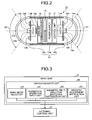
- FIG. 2 is a sectional schematic diagram illustrating an example of a configuration of a capsule endoscope illustrated in FIG. 1 .
- the capsule endoscope 10 includes a capsule-shaped casing 12 that is of an outer package formed in to a size easily guided into the internal organ of the subject and imaging units 11A and 11B that capture the image of the subject in imaging directions different from each other.
- the capsule endoscope 10 includes a wireless communication unit 16 that wirelessly transmits the images captured by the imaging units 11A and 11B to the outside, a control unit 17 that controls each component of the capsule endoscope 10, and a power supply 18 that supplies the electric power to each component of the capsule endoscope 10.
- the capsule endoscope 10 includes a permanent magnet 19 that enables the magnetic induction by the magnetic field generating unit 2.
- the capsule-shaped casing 12 is an outer casing formed in to a size easily guided into the internal organ of the subject, and is constructed by closing opening ends on both sides of a cylindrical casing 12a with a dome-shaped casings 12b and 12c.
- the dome-shaped casings 12b and 12c are dome-shaped optical members that are transparent to light having a predetermined wavelength band such as visible light.
- the cylindrical casing 12a is a colored casing that is substantially opaque to the visible light.
- the capsule-shaped casing 12 including the cylindrical casing 12a and the dome-shaped casings 12b and 12c includes the imaging units 11A and 11B, the wireless communication unit 16, the control unit 17, the power supply 18, and the permanent magnet 19 in a liquid-tight manner.
- the imaging units 11A and 11B capture the images in the directions different from each other.
- the imaging unit 11A includes an illumination unit 13A such as an LED, an optical system 14A such as a condenser lens, and an imaging element 15A such as a CMOS image sensor and a CCD.
- the illumination unit 13A emits illumination light such as white light to an imaging visual field S1 of the imaging element 15A to illuminate the subject (for example, the inner wall of the internal organ on the side of the imaging visual field S1 in the subject) in the imaging visual field S1 over the dome-shaped casing 12b.
- the optical system 14A condenses the light reflected from the imaging visual field S1 onto an imaging surface of the imaging element 15A, and forms the subject image in the imaging visual field S1 on the imaging surface of the imaging element 15A.
- the imaging element 15A receives the light reflected from the imaging visual field S1 through the imaging surface, performs a photoelectric conversion process to the received light signal, and captures the subject image in the imaging visual field S1, namely, the in-vivo image of the subject.
- the imaging unit 11B includes an illumination unit 13B such as an LED, an optical system 14B such as a condenser lens, and an imaging element 15B such as a CMOS image sensor and a CCD.
- the illumination unit 13B emits the illumination light such as the white light to an imaging visual field S2 of the imaging element 15B to illuminate the subject (for example, the inner wall of the internal organ on the side of the imaging visual field S2 in the subject) in the imaging visual field S2 over the dome-shaped casing 12c.
- the optical system 14B condenses the light reflected from the imaging visual field S2 onto an imaging surface of the imaging element 15B, and forms the subject image in the imaging visual field S2 on the imaging surface of the imaging element 15B.
- the imaging element 15B receives the light reflected from the imaging visual field S2 through the imaging surface, performs the photoelectric conversion process to the received light signal, and captures the subject image in the imaging visual field S2, namely, the in-vivo image of the subject.
- the capsule endoscope 10 is a binocular type capsule medical device that captures front and rear images in a direction of a long axis 21a as illustrated in FIG. 2
- optical axes of the imaging units 11A and 11B are substantially parallel or aligned with the long axis 21a that is of a center axis in the lengthwise direction of the capsule-shaped casing 12.
- the directions of the imaging visual fields S1 and S2 of the imaging units 11A and 11B, namely, imaging directions of the imaging units 11A and 11B are opposite to each other.
- the wireless communication unit 16 includes an antenna 16a, and sequentially and wirelessly transmits the images captured by the imaging units 11A and 11B to the outside through the antenna 16a. Specifically, the wireless communication unit 16 acquires the image signal of the in-vivo image of the subject, which is captured by the imaging unit 11A or 11B, from the control unit 17, performs a modulation process to the acquired image signal, and generates the radio signal in which the image signal is modulated. The wireless communication unit 16 transmits the radio signal to the transmitting/receiving unit 3 through the antenna 16a.
- the control unit 17 controls the operations of the imaging units 11A and 11B and the wireless communication unit 16, which are of the components of the capsule endoscope 10, and controls the input/output of the signal among the components. Specifically, the control unit 17 causes the imaging element 15A to capture the image of the subject in the imaging visual field S1 illuminated by the illumination unit 13A, and causes the imaging element 15B to capture the image of the subject in the imaging visual field S2 illuminated by the illumination unit 13B.
- the control unit 17 has a signal processing function of generating the image signal.
- the control unit 17 acquires the in-vivo image data in the imaging visual field S1 from the imaging element 15A, performs predetermined signal processing to the in-vivo image data in each case, and generates the image signal including the in-vivo image data in the imaging visual field S1. Similarly, the control unit 17 acquires the in-vivo image data in the imaging visual field S2 from the imaging element 15B, performs predetermined signal processing to the in-vivo image data in each case, and generates the image signal including the in-vivo image data in the imaging visual field S2. The control unit 17 controls the wireless communication unit 16 such that the image signals are sequentially and wirelessly transmitted to the outside in time series.
- the power supply 18 is an electric accumulator such as a button battery and a capacitor, and is constructed by the electric accumulator and a switch such as a magnetic switch.
- the power supply 18 switches between an on-state and an off-state of the power supply by the magnetic field applied from the outside, and properly supplies the electric power of the electric accumulator to each component (the imaging units 11A and 11B, the wireless communication unit 16, and the control unit 17) of the capsule endoscope 10 in the case of the off-state.
- the power supply 18 stops the supply of the electric power to each component of the capsule endoscope 10 in the case of the off-state.
- the permanent magnet 19 enables the magnetic field generating unit 2 to perform the magnetic induction of the capsule endoscope 10.
- the permanent magnet 19 is fixedly disposed in the capsule-shaped casing 12 while relatively fixed to the imaging units 11A and 11B.
- the permanent magnet 19 is magnetized in a well-known direction relatively fixed to vertical directions of the imaging surfaces of the imaging elements 15A and 15B.
- a contact mode and an away mode are set while correlated with each other as a guidance mode of the capsule endoscope 10.
- the contact mode is one, in which the capsule endoscope 10 is brought into contact with a desired boundary surface in plural boundary surfaces of a liquid in the subject while pressed the desired boundary surface.
- the away mode is one, in which the capsule endoscope 10 in contact with the desired boundary surface is moved away from the desired boundary surface.
- the contact mode corresponds to the case in which the capsule endoscope 10 is retained while brought into contact with the liquid level
- the away mode corresponds to the case in which the capsule endoscope 10 is moved away from the liquid level and guided downward into the liquid.
- the contact mode corresponds to the case in which the capsule endoscope 10 is retained while brought into contact with the stomach wall
- the away mode corresponds to the case in which the capsule endoscope 10 is moved away from the stomach wall and guided upward into the liquid.
- the magnetic induction corresponding to each mode is implemented such that the magnetic field generating unit 2 generates the uniform-gradient magnetic field.
- the gradient direction of the uniform-gradient magnetic field generated in each of the contact mode and the away mode is switched based on whether the capsule endoscope 10 is located in the upper portion or the lower portion in the stomach.
- the contact mode or the away mode is implemented by inputting selection information indicating whether the contact mode or the away mode is selected by the operation input unit 60 to the external control unit 4.
- FIG. 3 is a block diagram illustrating the configuration of the operation input unit 60 illustrated in FIG. 1
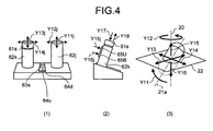
- FIG. 4 is a view illustrating an example of the operation input unit 60 illustrated in FIG. 1 and explaining the magnetic induction in the liquid level area of the capsule medical device that can be operated by the operation input unit 60
- FIG. 4(1) is a front view of the operation input unit 60
- FIG. 4(2) is a left side view of the operation input unit 60
- FIG. 4(3) is a view illustrating operation contents of the capsule endoscope 10 that is instructed by the operation of each component of the operation input unit 60.
- the operation input unit 60 includes an away/contact mode selector 61, a horizontal operation input unit 62, a magnetic field direction switching instruction unit 63, and a gradient adjustment instruction unit 64.
- the away/contact mode selector 61 inputs the selection information selecting one of the away mode and the contact mode to the external control unit 4.
- the away/contact mode selector 61 includes a away mode button 61s provided on the top of a joystick 62k.
- the away mode button 61s inputs the selection information selecting the away mode to the external control unit 4 by pressing the away mode button 61s as illustrated by an arrow Y17 of FIG. 4(2) .
- the away mode button 61s inputs the selection information selecting the contact mode to the external control unit 4 by releasing the pressing the away mode button 61s as illustrated by an arrow Y18 of FIG. 4(2) .
- the horizontal operation input unit 62 inputs the operation information on the magnetic induction in the horizontal direction of the capsule endoscope 10 by the magnetic field generating unit 2 to the external control unit 4.
- the horizontal operation input unit 62 includes two joysticks 62j and 62k.
- the joysticks 62j and 62k can be tilted in the vertical and horizontal directions, and the operation information is input to the external control unit 4 in order to three-dimensionally operate the magnetic induction of the capsule endoscope 10 by the magnetic field generating unit 2.
- the magnetic field direction switching instruction unit 63 performs the magnetic induction of the capsule endoscope 10 based on the liquid level that is of the boundary surface in the upper portion of the liquid in the stomach or the stomach wall of the bottom that is of the boundary surface in the lower portion of the liquid in the stomach, thereby inputting the instruction information issuing the instruction to switch the gradient direction of the uniform-gradient magnetic field generated in the contact mode and the away mode to the external control unit 4.
- the magnetic field direction switching unit 46 switches the gradient direction of the uniform-gradient magnetic field generated in each of the contact mode and the away mode to the predetermined direction in the case that the magnetic field direction switching instruction unit 63 issues the instruction to switch the gradient direction of the uniform-gradient magnetic field generated in each of the contact mode and the away mode.
- the magnetic field direction switching instruction unit 63 includes an up/down mode changeover switch 63s. For example, an up mode in which the magnetic induction of the capsule endoscope 10 is performed based on the liquid level that is of the boundary surface in the upper portion of the liquid in the stomach or the upper stomach wall and a down mode in which the magnetic induction of the capsule endoscope 10 is performed based on the stomach wall of the bottom that is of the boundary surface in the lower portion of the liquid in the stomach are set.
- the up/down mode changeover switch 63s is pressed to perform the display indicating that the up mode is selected, and outputs the instruction information issuing the instruction to switch the gradient direction of the uniform-gradient magnetic field generated in each of the contact mode and the away mode to the direction corresponding to the up mode to the external control unit 4.
- the up/down mode changeover switch 63s performs the display indicating that the down mode is selected by releasing the pressing, and outputs the instruction information issuing the instruction to switch the gradient direction of the uniform-gradient magnetic field generated in each of the contact mode and the away mode to the direction corresponding to the down mode to the external control unit 4.
- the gradient adjustment instruction unit 64 inputs the instruction information issuing the instruction to adjust the gradient of the uniform-gradient magnetic field generated in the away mode to the external control unit 4.
- the gradient adjustment instruction unit 64 includes a gradient up button 64u and a gradient down button 64d.
- the gradient up button 64u is pressed to input the instruction information indicating that the gradient of the uniform-gradient magnetic field is incremented by one stage to the external control unit 4.
- the gradient down button 64d is pressed to input the instruction information indicating that the gradient of the uniform-gradient magnetic field is decremented by one stage to the external control unit 4.
- a behavior of the capsule endoscope 10 corresponding to the tilt operations of the joysticks 62j and 62k will be described.
- the tilt in the vertical direction illustrated by an arrow 11j of the joystick 62j corresponds to a direction of a tilting behavior in which a front end of the capsule endoscope 10 oscillates so as to pass through a vertical axis 20 as illustrated by an arrow Y11 of FIG. 4(3) .
- the magnetic field control instruction unit 45 calculates an induction direction of the front end of the capsule endoscope 10 on an absolute coordinate system according to the tilt direction of the joystick 62j, and calculates an induction speed according to the tilt operation of the joystick 62j.
- the magnetic field control instruction unit 45 selects the peak magnetic field, which is switched by the magnetic field condition switching unit 46, as the applied magnetic field, and changes an angle formed between the orientation corresponding to the calculated induction direction and the vertical axis 20 in a vertical plane including the vertical axis 20 and a long axis 21a of the capsule endoscope 10.
- the tilt in the horizontal direction illustrated by an arrow 12j of the joystick 62j corresponds to a direction of a rotation behavior in which the capsule endoscope 10 rotates about the vertical axis 20 as illustrated by an arrow Y12 of FIG. 4(3) .
- the magnetic field control instruction unit 45 calculates the induction direction of the front end of the capsule endoscope 10 on the absolute coordinate system according to the tilt direction of the joystick 62j, calculates the induction speed according to the tilt operation of the joystick 62j, causes the magnetic field generating unit 2 to generate the peak magnetic field having the orientation corresponding to the calculated induction direction, and rotates the orientation of the peak magnetic field about the vertical axis 20 at the calculated induction speed.
- the tilt in the vertical direction illustrated by an arrow Y13j of the joystick 62k corresponds to a direction of a horizontal backward behavior or a horizontal forward behavior in which the capsule endoscope 10 travels in a direction, in which the long axis 21a of the capsule endoscope 10 is projected to a horizontal surface 22, as illustrated by an arrow Y13 of FIG. 4(3) .
- the magnetic field control instruction unit 45 calculates the induction direction and the induction position of the front end of the capsule endoscope 10 on the absolute coordinate system according to the tilt direction of the joystick 62k, calculates the induction speed according to the tilt operation of the joystick 62k, causes the magnetic field generating unit 2 to generate the peak magnetic field having the orientation corresponding to the calculated induction direction, and moves the peak of the peak magnetic field to the induction position at the calculated induction speed.
- the tilt in the horizontal direction illustrated by an arrow Y14j of the joystick 62k corresponds to a direction of a horizontal right behavior or a horizontal left behavior in which the capsule endoscope 10 travels perpendicular to a direction, in which the long axis 21a of the capsule endoscope 10 is projected to a horizontal surface 22, as illustrated by an arrow Y14 of FIG. 4(3) .
- the magnetic field control instruction unit 45 calculates the induction direction and the induction position of the front end of the capsule endoscope 10 on the absolute coordinate system according to the tilt direction of the joystick 62k, calculates the induction speed according to the tilt operation of the joystick 62k, causes the magnetic field generating unit 2 to generate the peak magnetic field having the orientation corresponding to the calculated induction direction, and moves the peak of the peak magnetic field to the induction position at the calculated induction speed.
- An up button 65U and a down button 65B are provided in a rear surface of the joystick 62k.
- An up behavior in which the capsule endoscope 10 travels upward along the vertical axis 20 as illustrated by an arrow Y15 of FIG. 4(3) is instructed in the case that the up button 65U is pressed as illustrated by an arrow Y15j of FIG. 4(2) .
- a down behavior in which the capsule endoscope 10 travels downward along the vertical axis 20 as illustrated by an arrow Y16 of FIG. 4(3) is instructed in the case that the down button 65B is pressed as illustrated by an arrow Y16j of FIG. 4(2) .
- the magnetic field control instruction unit 45 calculates the behavior direction of the front end of the capsule endoscope 10 on the absolute coordinate system according to which button is pressed, and causes the magnetic field generating unit 2 to generate the uniform-gradient magnetic field having the gradient along the vertical axis 20 according to the calculated behavior direction.
- the magnetic field generating unit 2 In the case that the up button 65U is pressed, the magnetic field generating unit 2 generates the uniform-gradient magnetic field having the gradient that becomes fine toward the upward direction of the vertical axis 20, thereby moving the capsule endoscope 10 as illustrated by the arrow Y15. In the case that the down button 65B is pressed, the magnetic field generating unit 2 generates the uniform-gradient magnetic field having the gradient that becomes fine toward the downward direction of the vertical axis 20, thereby moving the capsule endoscope 10 as illustrated by the arrow Y16.
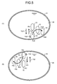
- FIG. 5 illustrates an example in which the capsule endoscope 10 is guided in the stomach to which a liquid 30 is introduced.
- the case in which the operator operates the up/down mode changeover switch 63s to select the down mode will be described with reference to FIG. 5(1) .
- This case corresponds to the case in which the instruction information issuing the instruction to select the up mode is input from the operation input unit 60.
- the magnetic induction of the capsule endoscope 10 is performed based on a stomach wall 31 of the bottom in the boundary surface of the liquid 30.
- the contact mode corresponds to the mode in which the capsule endoscope 10 is retained while pressed against the stomach wall 31 of the bottom. Therefore, in the contact mode, it is necessary for the magnetic field control instruction unit 45 to cause the magnetic field generating unit 2 to generate the magnetic field having a magnetic attraction force in the downward direction of the vertical axis.
- the magnetic field direction switching unit 46 issues the instruction to switch the gradient direction of the uniform-gradient magnetic field in the contact mode to the downward direction of the vertical axis to the magnetic field control instruction unit 45.
- the away mode corresponds to the mode in which the capsule endoscope 10 is moved upward from the stomach wall 31 of the bottom. Therefore, in the away mode, it is necessary for the magnetic field control instruction unit 45 to cause the magnetic field generating unit 2 to generate the magnetic field having the magnetic attraction force in the upward direction of the vertical axis.
- the magnetic field direction switching unit 46 issues the instruction to switch the gradient direction of the uniform-gradient magnetic field in the away mode to the upward direction of the vertical axis to the magnetic field control instruction unit 45.
- the gradient direction of the uniform-gradient magnetic field in the contact mode and the gradient direction of the uniform-gradient magnetic field in the away mode are set in opposite directions to each other.
- the magnetic field control instruction unit 45 causes the magnetic field generating unit 2 to generate the uniform-gradient magnetic field having the vertically downward gradient in which the capsule endoscope 10 is pressed at the position Pu0 of the bottom.
- the capsule endoscope 10 retains a stable rest state as illustrated by an arrow Yu0 because the capsule endoscope 10 is pressed at the position Pu0 against the stomach wall 31 of the bottom that becomes the reference.
- the magnetic field control instruction unit 45 causes the magnetic field generating unit 2 to generate the uniform-gradient magnetic field having the vertically upward gradient in which the capsule endoscope 10 is moved upward.
- the capsule endoscope 10 floats from the position Pu0 of the stomach wall 31 and is moved to a position Pu1 as illustrated by an arrow Yu1.
- the magnetic field control instruction unit 45 may store the magnetic field generating condition of the contact mode before the away mode is switched.
- the magnetic field control instruction unit 45 causes the magnetic field generating unit 2 to generate the uniform-gradient magnetic field having the vertically downward gradient identical to that before the away mode is selected, and stabilizes the capsule endoscope 10 by pressing the capsule endoscope 10 against the stomach wall 31 of the bottom at the position Pu0 that becomes the reference.
- the magnetic field control instruction unit 45 causes the magnetic field generating unit 2 to generate the uniform-gradient magnetic field having the magnetic gradient in the direction corresponding to the direction of the instruction of the horizontal movement while causing the magnetic field generating unit 2 to generate the uniform-gradient magnetic field having the vertically upward gradient corresponding to the away mode.
- the capsule endoscope 10 moves horizontally in the liquid from the position Pu0 to a position Pu3 through a position Pu2 while jumping obliquely upward as illustrated by an arrow Yu3.
- the case in which the operator operates the up/down mode changeover switch 63s to switch from the down mode to the up mode will be described with reference to FIG. 5(2) .
- This case corresponds to the case in which the instruction information issuing the instruction to select the up mode is input from the operation input unit 60.
- the magnetic induction of the capsule endoscope 10 is performed based on the upper stomach wall 31 in the boundary surface of the liquid 30 or the liquid level.
- the contact mode corresponds to the mode in which the capsule endoscope 10 is retained while pressed against the upper stomach wall 31 or the liquid level. Therefore, in the contact mode, it is necessary for the magnetic field control instruction unit 45 to cause the magnetic field generating unit 2 to generate the magnetic field having the magnetic attraction force in the upward direction of the vertical axis.
- the magnetic field direction switching unit 46 issues the instruction to switch the gradient direction of the uniform-gradient magnetic field in the contact mode to the upward direction of the vertical axis to the magnetic field control instruction unit 45.
- the away mode corresponds to the mode in which the capsule endoscope 10 is moved downward from the upper stomach wall 31 or the liquid level. Therefore, in the away mode, it is necessary for the magnetic field control instruction unit 45 to cause the magnetic field generating unit 2 to generate the magnetic field having the magnetic attraction force in the downward direction of the vertical axis.
- the magnetic field direction switching unit 46 issues the instruction to switch the gradient direction of the uniform-gradient magnetic field in the away mode to the downward direction of the vertical axis to the magnetic field control instruction unit 45.
- the gradient direction of the uniform-gradient magnetic field in the contact mode and the gradient direction of the uniform-gradient magnetic field in the away mode are set in opposite directions to each other.
- the magnetic field direction switching unit 46 switches between the gradient direction of the uniform-gradient magnetic field in the contact mode and the gradient direction of the uniform-gradient magnetic field in the away mode such that the gradient direction of the uniform-gradient magnetic field in the contact mode and the gradient direction of the uniform-gradient magnetic field in the away mode are inverted by switching from the up mode to the down mode.
- the switching from the down mode to the up mode means that the reference plane of the magnetic induction of the capsule endoscope 10 is switched from the lower stomach wall 31 to the upper stomach wall 31 or the liquid level.
- the up/down mode changeover switch 63s is switched from the up mode to the down mode to issue the instruction to invert the gradient direction of the uniform-gradient magnetic field in the contact mode and the gradient direction of the uniform-gradient magnetic field in the away mode.
- the magnetic field control instruction unit 45 causes the magnetic field generating unit 2 to generate the uniform-gradient magnetic field having the vertically upward gradient in which the capsule endoscope 10 is pressed at the position Pt0 of the upper stomach wall 31.
- the capsule endoscope 10 retains the stable rest state as illustrated by an arrow Yt0 because the capsule endoscope 10 is pressed at the position Pt0 against the upper stomach wall 31 that becomes the reference.
- the magnetic field control instruction unit 45 causes the magnetic field generating unit 2 to generate the uniform-gradient magnetic field having the vertically downward gradient in which the capsule endoscope 10 is moved downward.
- the capsule endoscope 10 sinks in the liquid 30 from the position Pt0 of the stomach wall 31 and is moved to a position Pt1 as illustrated by an arrow Yt1.
- the magnetic field control instruction unit 45 causes the magnetic field generating unit 2 to generate the uniform-gradient magnetic field having the vertically upward gradient, and stabilizes the capsule endoscope 10 by pressing the capsule endoscope 10 against the upper stomach wall 31 at the position Pt0 that becomes the reference.
- the magnetic field control instruction unit 45 causes the magnetic field generating unit 2 to generate the uniform-gradient magnetic field having the magnetic gradient in the direction corresponding to the direction of the instruction of the horizontal movement while causing the magnetic field generating unit 2 to generate the uniform-gradient magnetic field having the vertically downward gradient corresponding to the away mode.
- the capsule endoscope 10 moves horizontally in the liquid from the position Pt0 to a position Pt3 through a position Pt2 while jumping obliquely downward as illustrated by an arrow Yt3.
- the magnetic field direction switching unit 46 switches between the gradient direction of the uniform-gradient magnetic field in the contact mode and the gradient direction of the uniform-gradient magnetic field in the away mode such that the gradient direction of the uniform-gradient magnetic field in the contact mode and the gradient direction of the uniform-gradient magnetic field in the away mode are inverted, and the magnetic field generating unit 2 generates the uniform-gradient magnetic field having the gradient in the direction corresponding to each mode.
- the capsule endoscope 10 can automatically and stably be retained in the desired boundary surface such that only the operator switches the up/down mode changeover switch 63s to the desired mode. Therefore, it is not necessary for the operator to perform movement operation of the capsule endoscope 10.
- the operator presses the away mode button 61s only for a time the zoom back is performed. Only the joystick 62k is laid in the desired direction while away mode button 61s is pressed, which allows the capsule endoscope 10 to jump and move in the liquid. The operator can issue the instructions of various operations of the capsule endoscope 10 by the simple operation.
- the operator may operate the joysticks 62j and 62k without pressing the away mode button 61s while selecting the down mode.
- the contact mode is implemented, and the capsule endoscope 10 moves in the instructed induction direction while contacting with the stomach wall 31 of the bottom.
- a projection 101 such as a plica and a polyp which becomes an induction obstacle of the capsule endoscope 10 is discovered at a position Pu41 in the induction direction, it is necessary for the capsule endoscope 10 to jump over the projection 101 in order to continue the observation.
- the operator lays the joystick 62k onto the induction direction side while pressing the away mode button 61s. Therefore, the capsule endoscope 10 jumps and moves in the induction direction, so that the capsule endoscope 10 can move to a position Pu42 beyond the projection 101 as illustrated by an arrow Yu43. Then the operator releases an operator's finger from the away mode button 61s. As a result, the contact mode is implemented, and the magnetic field generating unit 2 generated the magnetic field having the same condition as that before the away mode button 61s is pressed, so that the capsule endoscope 10 can continuously be guided under the same condition as that before the away mode button 61s is pressed.
- the up mode is selected in addition to the case of the down mode.
- the capsule endoscope 10 in the case that the capsule endoscope 10 is guided along the upper stomach wall 31 in order to observe the interior portion of the lower stomach, when a projection 102 is discovered at a position Pt41, the operator may lay the joystick 62k while pressing the away mode button 61s. Therefore, the capsule endoscope 10 jumps over the projection 102 and moves to a position Pt42 as illustrated by an arrow Yt43. Then the operator releases the operator's finger from the away mode button 61s. Therefore, because the magnetic field having the same condition as that before the away mode button 61s is pressed is generated, the capsule endoscope 10 can continuously be guided under the same condition as that before the away mode button 61s is pressed.
- the various behaviors of the capsule endoscope 10 can be implemented only by performing the above simple operation.
- the operator lays the joystick 62j onto the front side or the rear side to horizontally tilt the joystick 62j while releasing the operator's finger from the away mode button 61s.
- the behavior of the operation input unit 60 issues the instruction to the external control unit 4 to tilt and swivel the posture of the capsule endoscope 10 while the instruction of the contact mode is issued, and the magnetic field generating unit 2 generates the magnetic fields corresponding to the instructions.
- the operator can also capture the image in the stomach at an optimum camera angle from the desired position of the stomach wall 31 only by performing the simple operation while the capsule endoscope 10 is not destabilized.
- the up mode In the case that the capsule endoscope 10 is swiveled about the long axis 21a at the position Pt42 of the upper stomach wall 31 in selecting the up mode, the operator lays the joystick 62j onto the front side or the rear side to horizontally tilt the joystick 62j while releasing the operator's finger from the away mode button 61s.
- the operator may release the operator's finger from the away mode button 61s to release the zoom back.
- the capsule endoscope 10 returns automatically to the boundary surface and comes to rest.
- the operator can quickly stabilize the capsule endoscope 10 only by releasing the operator's finger from the away mode button 61s.
- the operator can continue the in-vivo observation because the capsule endoscope 10 can quickly be immobilized and stabilized in the reference plane.
- the operator switches between the stable state and the behavior state in the binary manner without setting the condition corresponding to the desired behavior from many complicated magnetic field conditions, so that the capsule endoscope existing in the liquid can stably be induced by the simple operation.
- the operator further presses one of the gradient up button 64u and the gradient down button 64d while pressing the away mode button 61s, which allows the adjustment of the gradient of the uniform-gradient magnetic field applied in the away mode. That is, the gradient of the uniform-gradient magnetic field, which is applied in order to move the capsule endoscope 10 away from the boundary surface, can be adjusted while the uniform-gradient magnetic field is applied.
- the magnitude of the magnetic gradient is proportional to the magnitude of the magnetic attraction force. Therefore, in the away mode, a speed at which the capsule endoscope 10 leaves the boundary surface can be controlled by adjusting the magnitude of the magnetic gradient.
- the gradient magnetic field cannot be generated with the completely uniform magnetic gradient in the space in which the capsule endoscope 10 is guided, and the generated magnetic field varies according to the position in the space. Therefore, the magnetic gradient changes in the vertical direction according to the position of the capsule endoscope 10.
- the operator can instruct the optimum magnetic gradient using the gradient up button 64u and the gradient down button 64d. Accordingly, the operator continuously presses the away mode button 61s, and the operator presses the gradient up button 64u and the gradient down button 64d to adjust the speed, at which the capsule endoscope 10 leaves the boundary surface, while acknowledging the in-vivo image of the capsule endoscope 10 on the display unit 5, so that the in-vivo image can be observed at the optimum observation speed.
- an initial condition of the gradient of the applied uniform-gradient magnetic field is set to a relatively small gradient.
- the magnetic field control instruction unit 45 stores the gradient of the uniform-gradient magnetic field, which the gradient adjustment instruction unit 64 issues the instruction to apply in the away mode, in the magnetic field gradient storage unit 47.
- the magnetic field control instruction unit 45 causes the magnetic field generating unit 2 to generate the uniform-gradient magnetic field such that the uniform-gradient magnetic field has the gradient in response to the instruction from the gradient adjustment instruction unit 64, and the magnetic field control instruction unit 45 updates the gradient of the uniform-gradient magnetic field stored in the magnetic field gradient storage unit to the latest gradient.
- the magnetic field control instruction unit 45 causes the magnetic field generating unit 2 to generate the uniform-gradient magnetic field corresponding to the away mode such that the magnetic gradient stored in the magnetic field gradient storage unit 47 is provided.
- the operation input unit 60 includes the gradient up button 64u and the gradient down button 64d, which are of the gradient instruction units that issue instructions regarding the optimum condition of the magnetic gradient of the generated magnetic field in the case that the away mode is selected.
- the magnetic field gradient storage unit 47 stores the magnetic gradient of the generated magnetic field as the optimum condition therein in the case that the away mode is selected.
- the magnetic field control instruction unit 45 causes the magnetic field generating unit 2 to generate the magnetic gradient of the optimum condition stored in the magnetic field gradient storage unit 47.
- the in-vivo observation can be performed while the capsule endoscope 10 is moved away from the boundary surface at the optimum away speed already adjusted.
- the operator can perform the in-vivo observation at the optimum away speed only by pressing the away mode button 61s. Therefore, it is not necessary for the operator to finely adjust the magnetic gradient in the vertical direction with the joystick every time the away mode button 61s is pressed, but the operability is improved.
- the gradient of the uniform-gradient magnetic field in the away mode is individually stored in each of the up mode and down mode, and the up mode or down mode is returned after switched to another mode.
- the external control unit 4 may cause the magnetic field generating unit 2 to generate the uniform-gradient magnetic field in the away mode with the gradient stored in the original up mode or down mode.
- the adjustment process of the magnetic gradient can also be simplified.
- the up mode in which the magnetic induction of the capsule endoscope 10 is performed based on the liquid level that is of the upper boundary surface of the liquid in the stomach or the upper stomach wall and the down mode in which the magnetic induction of the capsule endoscope 10 is performed based on the stomach wall of the bottom that is of the lower boundary surface of the liquid in the stomach are set by way of example.
- the invention is not limited to the first embodiment.
- a mode in which the magnetic induction of the capsule endoscope 10 is performed based on one of the right and left stomach walls in the stomach may further be set. In the case of this mode, for example, as illustrated in FIG.
- the operator may lay the joystick 62k onto the guidance direction side while pressing the away mode button 61s.
- the capsule endoscope 10 moves to a position Ps42 beyond the projection 103 by the operation.
- the operator lays the joystick 62j onto the front side or the rear side to horizontally tilt the joystick 62j while releasing the operator's finger from the away mode button 61s.
- FIG. 8 is a flowchart illustrating a procedure of the guidance process of the capsule endoscope 10 of the capsule medical device guidance system 1 illustrated in FIG. 1 .
- the magnetic field control instruction unit 45 sets the generation of the magnetic field on the initial condition (Step S4), and the magnetic field control instruction unit 45 causes the magnetic field controller 8 to generate the magnetic field on the initial condition.
- the magnetic field control instruction unit 45 causes the magnetic field generating unit 2 to generate the uniform-gradient magnetic field corresponding to the contact mode in the up mode as the initial condition.
- the image receiving unit 41 starts image receiving process of sequentially acquiring the in-vivo images received by the transmitting/receiving unit 3 (Step S6), and the image display controller 42 starts image display process of displaying the in-vivo images sequentially received by the transmitting/receiving unit 3 on the display unit 5 (Step S8).
- the magnetic field direction switching unit 46 determines whether the magnetic field direction switching instruction unit 63 of the operation input unit 60 issues the instruction to switch between the up and down modes (Step S10). When the magnetic field direction switching unit 46 determines that the magnetic field direction switching instruction unit 63 issues the instruction to switch between the up and down modes (Yes in Step S10), because the boundary surface that becomes the reference plane is vertically inverted, the magnetic field direction switching unit 46 performs magnetic field direction inverting process of issuing the instruction to the magnetic field control instruction unit 45 to invert both the gradient direction of the uniform-gradient magnetic field in the contact mode and the gradient direction of the uniform-gradient magnetic field in the away mode (Step S12).
- the magnetic field control instruction unit 45 performs contact magnetic field applying process of applying the uniform-gradient magnetic field in the contact mode to the capsule endoscope 10 (Step S14) after inverting the gradient direction of the uniform-gradient magnetic field in the contact mode and the gradient direction of the uniform-gradient magnetic field in the away mode in response to the instruction of the magnetic field direction switching unit 46.
- the capsule endoscope 10 is retained so as to be pressed against the reference plane corresponding to the newly-switched up mode or down mode.
- the magnetic field control instruction unit 45 performs contact magnetic field applying process of applying the uniform-gradient magnetic field in the contact mode to the capsule endoscope 10 (Step S14) while the gradient direction of the uniform-gradient magnetic field in the contact mode and the gradient direction of the uniform-gradient magnetic field in the away mode are left without change.
- the magnetic field control instruction unit 45 determines whether the instruction to start the away mode is issued based on the selection information from the away mode selector 61 (Step S16). When determining that the instruction to start the away mode is not issued (No in Step S16), the magnetic field control instruction unit 45 continues the contact magnetic field applying process in Step S14 to maintain the contact mode. On the other hand, when determining that the instruction to start the away mode is issued (Yes in Step S16), the magnetic field control instruction unit 45 performs an away magnetic field applying process of applying the uniform-gradient magnetic field in the away mode to the capsule endoscope 10 (Step S18). Therefore, the capsule endoscope 10 leaves the reference plane to move in the liquid.
- the magnetic field control instruction unit 45 determines whether a gradient change instruction is issued based on the gradient adjustment instruction information from the gradient adjustment instruction unit 64 (Step S20). When determining that the gradient change instruction is issued (Yes in Step S20), the magnetic field control instruction unit 45 changes the gradient of the uniform-gradient magnetic field in the away mode according to the gradient adjustment instruction information (Step S22), and the magnetic field control instruction unit 45 applies the uniform-gradient magnetic field in the away mode with the changed gradient (Step S24). Therefore, the speed at which the capsule endoscope 10 leaves the boundary surface is adjusted. The magnetic field control instruction unit 45 performs gradient update process of updating the gradient in the away mode, which is stored in the magnetic field gradient storage unit 47, to the newly changed gradient (Step S26).
- the magnetic field control instruction unit 45 determines whether a horizontal movement instruction is issued based on the operation information on the horizontal direction of the horizontal operation input unit 62 (Step S28). When determining that the horizontal movement instruction is issued (Yes in Step S28), the magnetic field control instruction unit 45 calculates the horizontal movement position in response to the instruction of the operation information from the horizontal operation input unit 62 (Step S30), and the magnetic field control instruction unit 45 performs horizontal movement magnetic field applying process to the magnetic field generating unit 2 to apply the magnetic field to the capsule endoscope 10 such that the capsule endoscope 10 moves to the calculated movement position (Step S32). As a result, the capsule endoscope 10 jumps and moves horizontally in the liquid according to the operation process of the operation input unit 60.
- the magnetic field control instruction unit 45 determines whether an instruction to stop the away mode is issued based on the selection information of the away mode selector 61 (Step S34). That is, the magnetic field control instruction unit 45 determines whether an instruction to start the contact mode is issued.
- the magnetic field control instruction unit 45 performs contact magnetic field applying process of applying the uniform-gradient magnetic field in the contact mode to the capsule endoscope 10 (Step S36), thereby returning the capsule endoscope 10 to the reference plane.
- the magnetic field control instruction unit 45 determines that the instruction to stop the away mode is not issued (No in Step S34)
- the flow returns to Step S18 to continue the away mode.
- Step S36 After the magnetic field control instruction unit 45 performs the contact magnetic field applying process (Step S36) in response to the instruction to stop the away mode, the external control unit 4 determines whether the in-vivo observation is ended based on the instruction information input from the input unit 6 (Step S38). When determining that the in-vivo observation is not ended (No in Step S38), the external control unit 4 returns to Step S10 to continue the in-vivo observation, and the external control unit 4 determines whether the instruction to switch between the up and down mode is issued. When the external control unit 4 determines that the in-vivo observation is ended (Yes in Step S38), the image receiving process of the image receiving unit 41 is ended (Step S40), and the image display process of the image display controller 42 is ended (Step S42).
- the external control unit 4 performs image data storing process of storing the in-vivo image group captured by the capsule endoscope 10 in the storage unit 7 while the in-vivo image group is collected into one folder (Step S44), and the in-vivo observation is ended.
- FIG. 9 is a flowchart illustrating a procedure of the away magnetic field applying process illustrated in FIG. 8 .
- the magnetic field control instruction unit 45 determines whether the capsule endoscope 10 is located in the liquid level (Step S50).
- the operator determines that the capsule endoscope 10 is located in the liquid level by acknowledging the imaging screen of the capsule endoscope 10 displayed on the display unit 5, the operator inputs the information indicating that the capsule endoscope 10 is located in the liquid level.
- the information indicating that the capsule endoscope 10 is located in the liquid level is input from the input unit 6, whereby the magnetic field control instruction unit 45 determines that the capsule endoscope 10 is located in the liquid level.
- the magnetic field control instruction unit 45 When determining that the capsule endoscope 10 is located in the liquid level (Yes in Step S50), the magnetic field control instruction unit 45 performs a surface tension counteracting magnetic field generating process to the magnetic field generating unit 2 in order to temporarily generate the magnetic field having high strength that can counteract the surface tension of the liquid level (Step S52).
- a large magnetic force is required to sink the capsule endoscope 10 in the liquid due to the surface tension.
- the operator manually adjusts the gradient of the uniform-gradient magnetic field in the away mode it is necessary to increase the gradient until the surface tension can be removed.
- the surface tension counteracting magnetic field generating process is performed in the case that the capsule endoscope 10 is located in the liquid level, and the capsule endoscope 10 can be guided at the desired speed of the operator while smoothly moved in the liquid with no obstruction of the surface tension.
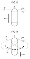
- the magnetic field generating unit 2 temporarily generates the strong magnetic field in the downwardly vertical direction to move the capsule endoscope 10 from a liquid level 30s into the liquid 30 as illustrated by an arrow M1 of FIG. 10 .
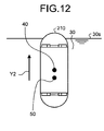
- the magnetic field generating unit generates a magnetic field M2 in order that the capsule endoscope 10 performs the tilting behavior at high speed as illustrated in FIG. 11 , and the posture of the capsule endoscope 10 may be changed at high speed.
- a sidewall of the capsule endoscope 10 exposed from the liquid level 30s wets by the liquid to weaken an influence of the surface tension.
- the magnetic field generating unit 2 generates the magnetic field to downwardly move the capsule endoscope 10 as illustrated by an arrow Y41, whereby the capsule endoscope 10 is moved from the liquid level 30s into the liquid or to the bottom.
- the capsule endoscope 10 can be guided from the liquid level 39s into the liquid or to the bottom even by the low magnetic field strength.
- the magnetic field control instruction unit 45 When determining that the capsule endoscope 10 is not located in the liquid level (No in Step S50), the magnetic field control instruction unit 45 performs the surface tension counteracting magnetic field generating process (Step S52), the magnetic field control instruction unit 45 causes the magnetic field generating unit 2 to apply the uniform-gradient magnetic field in the away mode to the capsule endoscope 10 (Step S54), and the away magnetic field applying process is ended. It is not always necessary to perform the surface tension counteracting magnetic field generating process, but the surface tension counteracting magnetic field generating process may be performed only in the case that the performance of the surface tension counteracting magnetic field generating process is previously set.
- the stable guidance of the capsule endoscope existing in the liquid is implemented by performing the pieces of processing of FIGS. 8 and 9 .
- the capsule endoscope 10 drifts in the liquid in which a balance between the buoyant force and the gravity is established by way of example.
- the invention is not limited to the first embodiment.
- a capsule endoscope 210 that drifts in the liquid 30 as illustrated by an arrow Y2 may be used.
- the dispositions of the components of the capsule endoscope 210 are adjusted such that the buoyant force of the capsule endoscope 210 is larger than the gravity of the capsule endoscope 210, whereby a specific weight to the liquid 30 is smaller than 1.
- the numeral 40 designates a geometric center of the capsule endoscope 210
- the numeral 50 designates the gravity of the capsule endoscope 210.
- the movement of the capsule endoscope 210 will be described below with reference to FIG 13 .
- the case in which the down mode is selected will be described with reference to FIG. 13(1) .
- the magnetic induction of the capsule endoscope 210 is performed based on the stomach wall 31 of the bottom in the boundary surface of the liquid.
- the contact mode corresponds to the mode in which the capsule endoscope 210 is brought into contact with the stomach wall 31 of the bottom. Therefore, in the down mode, the magnetic field direction switching unit 46 issues the instruction to the magnetic field control instruction unit 45 to switch the gradient direction of the uniform-gradient magnetic field in the contact mode to the downward direction of the vertical axis.
- the away mode corresponds to the mode in which the capsule endoscope 210 is moved upward from the stomach wall 31 of the bottom.
- the capsule endoscope 210 floats up naturally to the upper stomach wall 31 or the liquid level by the buoyant force thereof. Therefore, in the away mode, because the capsule endoscope 210 may be moved upward from the stomach wall 31 of the bottom by utilizing the floating of the capsule endoscope 210, the magnetic field control instruction unit 45 may stop the generation of the vertically downward gradient magnetic field that is generated in the contact mode by the magnetic field generating unit 2.
- the magnetic field control instruction unit 45 may control the magnetic field generating unit 2 such that the vertically upward magnetic gradient is generated within a range where a total force of the buoyant force and the gravity of the capsule endoscope 210 and the vertically downward magnetic attraction force becomes upward.
- the magnetic field control instruction unit 45 causes the magnetic field generating unit 2 to generate the uniform-gradient magnetic field having the vertically downward gradient in which the capsule endoscope 210 is pressed at the position Pu0 of the bottom.
- the capsule endoscope 210 retains the stable rest state as illustrated by an arrow Yu10 because the capsule endoscope 210 is pressed at the position Pu0 against the stomach wall 31 of the bottom that becomes the reference.
- the magnetic field control instruction unit 45 stops the uniform-gradient magnetic field having the vertically downward gradient, which is generated by the magnetic field generating unit 2.
- the capsule endoscope 210 floats up from the position Pu0 of the stomach wall 31 and leaves to the position Pu1 as illustrated by an arrow Yu11.
- the magnetic field control instruction unit 45 causes the magnetic field generating unit 2 to generate the uniform-gradient magnetic field having the vertically downward gradient, and stabilizes the capsule endoscope 210 by pressing the capsule endoscope 210 against the stomach wall 31 of the bottom at the position Pu0 that becomes the reference as illustrated by an arrow Yu12.
- the magnetic field control instruction unit 45 causes the magnetic field generating unit 2 to generate the uniform-gradient magnetic field having the magnetic gradient in the direction corresponding to the direction of the instruction of the horizontal movement while causing the magnetic field generating unit 2 to halt to generate the uniform-gradient magnetic field having the vertically downward gradient.
- the capsule endoscope 210 moves horizontally in the liquid from the position Pu0 to the position Pu3 through the position Pu2 while jumping obliquely upward as illustrated by an arrow Yu13.
- the up/down mode changeover switch 63s to switch from the down mode to the up mode will be described with reference to FIG. 13(2) .
- the magnetic induction of the capsule endoscope 210 is performed based on the upper stomach wall 31 or the liquid level in the boundary surface of the liquid 30.
- the contact mode corresponds to the mode in which the capsule endoscope 210 is retained while being in contact with the upper stomach wall 31 or the liquid level.
- the magnetic field control instruction unit 45 may control the magnetic field generating unit 2 such that the magnetic field generating unit 2 does not generates at least the uniform-gradient magnetic field having the vertically downward gradient.
- the magnetic field control instruction unit 45 causes the magnetic field generating unit 2 to generate the magnetic field having the magnetic attraction force in the downward direction of the vertical axis.
- the magnetic field direction switching unit 46 issues the instruction to the magnetic field control instruction unit 45 to switch the gradient direction of the uniform-gradient magnetic field in the away mode of the up mode to the downward direction of the vertical axis.
- the magnetic field control instruction unit 45 controls the magnetic field generating unit 2 such that the magnetic field generating unit 2 does not generate at least the uniform-gradient magnetic field having the vertically downward gradient.
- the capsule endoscope 210 retains the stable rest state as illustrated by the arrow Yt10, because the capsule endoscope 210 floats up and comes into contact with the position Pt0 of the upper stomach wall 31 that becomes the reference by the buoyant force thereof.
- the magnetic field control instruction unit 45 causes the magnetic field generating unit 2 to generate the uniform-gradient magnetic field having the vertically downward gradient in which the capsule endoscope 210 is moved downward.
- the capsule endoscope 210 sinks from the position Pt0 of the stomach wall 31 into the liquid 30 and leaves to a position Pt1 as illustrated by the arrow Yt11.
- the magnetic field control instruction unit 45 causes the magnetic field generating unit 2 to stop the generation of the uniform-gradient magnetic field having the vertically downward gradient.
- the capsule endoscope 210 retains the stable rest state as illustrated by the arrow Yt12, because the capsule endoscope 210 floats up and comes into contact with the position Pt0 of the upper stomach wall 31 that becomes the reference by the buoyant force thereof.
- the magnetic field control instruction unit 45 causes the magnetic field generating unit 2 to generate the uniform-gradient magnetic field having the magnetic gradient in the direction corresponding to the direction of the instruction of the horizontal movement while causing the magnetic field generating unit 2 to generate the uniform-gradient magnetic field having the vertically downward gradient corresponding to the away mode.
- the capsule endoscope 210 moves horizontally in the liquid from the position Pt0 to the position Pt3 through the position Pt2 while jumping obliquely downward as illustrated by the arrow Yt13.
- the magnetic field control instruction unit 45 causes the magnetic field generating unit 2 to generate the uniform-gradient magnetic field having the gradient in the upward direction of the vertical axis, and the capsule endoscope 210 may be pressed against the upper stomach wall 31 or the liquid level to securely bring the capsule endoscope 210 into contact with the stomach wall 31.
- the capsule endoscope 210 that floats in the liquid can stably be guided by controlling the generation of the uniform-gradient magnetic field having the gradient in the vertical axis direction in the contact mode and the away mode of the up mode and the down mode.
- a capsule endoscope 310 that sinks in the liquid as illustrated by an arrow Y3 of FIG. 14 can also be used.
- the dispositions of the components of the capsule endoscope 310 are adjusted such that the gravity of the capsule endoscope 310 is larger than the buoyant force of the capsule endoscope 310, whereby the specific weight to the liquid 30 is larger than 1.
- the movement of the capsule endoscope 310 will be described below with reference to FIG. 15 .
- the case in which the down mode is selected will be described with reference to FIG. 15(1) .
- the magnetic induction of the capsule endoscope 310 is performed based on a stomach wall 31 of the bottom in the boundary surface of the liquid.
- the contact mode corresponds to the mode in which the capsule endoscope 310 is brought into contact with the stomach wall 31 of the bottom.
- the capsule endoscope 310 sinks naturally to the stomach wall 31 of the bottom by the gravity thereof.
- the magnetic field control instruction unit 45 may control the magnetic field generating unit 2 such that the magnetic field generating unit 2 does not generates at least the vertically upward gradient magnetic field.
- the magnetic field control instruction unit 45 causes the magnetic field generating unit 2 to generate the magnetic field having the magnetic attraction force in the upward direction of the vertical axis.
- the magnetic field direction switching unit 46 issues the instruction to the magnetic field control instruction unit 45 to switch the gradient direction of the uniform-gradient magnetic field in the away mode from the down mode to the upward direction of the vertical axis.
- the magnetic field control instruction unit 45 controls the magnetic field generating unit 2 such that the magnetic field generating unit 2 does not generate at least the uniform-gradient magnetic field having the vertically upward gradient.
- the capsule endoscope 310 retains the stable rest state as illustrated by an arrow Yu20, because the capsule endoscope 310 sinks and comes into contact with the position Pu0 of the bottom that becomes the reference by the gravity thereof.
- the magnetic field control instruction unit 45 causes the magnetic field generating unit 2 to generate the uniform-gradient magnetic field having the vertically upward gradient in which the capsule endoscope 310 is moved upward.
- the capsule endoscope 310 floats up from the position Pu0 of the stomach wall 31 and leaves to a position Pu1 as illustrated by an arrow Yu21.
- the magnetic field control instruction unit 45 causes the magnetic field generating unit 2 to stop the generation of the uniform-gradient magnetic field having the vertically upward gradient.
- the capsule endoscope 310 retains the stable rest state as illustrated by an arrow Yu22, because the capsule endoscope 310 sinks and comes into contact with the position Pu0 of the stomach wall 31 of the bottom that becomes the reference by the gravity thereof.
- the magnetic field control instruction unit 45 causes the magnetic field generating unit 2 to generate the uniform-gradient magnetic field having the magnetic gradient in the direction corresponding to the direction of the instruction of the horizontal movement while causing the magnetic field generating unit 2 to generate the uniform-gradient magnetic field having the vertically upward gradient corresponding to the away mode.
- the capsule endoscope 310 moves horizontally in the liquid from the position Pu0 to the position Pu3 through the position Pu2 while jumping obliquely upward as illustrated by an arrow Yu23.
- the magnetic field control instruction unit 45 causes the magnetic field generating unit 2 to generate the uniform-gradient magnetic field having the gradient in the upward direction of the vertical axis, and the capsule endoscope 310 may be pressed against the upper stomach wall 31 of the bottom to securely bring the capsule endoscope 310 into contact with the stomach wall 31.
- the magnetic induction of the capsule endoscope 310 is performed based on the upper stomach wall 31 or the liquid level in the boundary surface of the liquid 30.
- the magnetic field direction switching unit 46 issues the instruction to the magnetic field control instruction unit 45 to switch the gradient of the uniform-gradient magnetic field to the upward direction of the vertical axis.
- the away mode corresponds to the mode in which the capsule endoscope 310 is moved downward from the upper stomach wall 31 or the liquid level.
- the magnetic field control instruction unit 45 may control the magnetic field generating unit 2 such that the magnetic field generating unit 2 does not generates at least the vertically upward gradient magnetic field.
- the magnetic field control instruction unit 45 may control the magnetic field generating unit 2 such that the vertically upward magnetic gradient is generated within a range where a total force of the buoyant force and the gravity of the capsule endoscope 310 and the vertically upward magnetic attraction force becomes downward.
- the magnetic field control instruction unit 45 causes the magnetic field generating unit 2 to generate the uniform-gradient magnetic field having the vertically upward gradient.
- the capsule endoscope 310 retains the stable rest state as illustrated by an arrow Yt20 because the capsule endoscope 310 is pressed at the position Pt0 against the upper stomach wall 31 that becomes the reference.
- the magnetic field control instruction unit 45 controls the magnetic field generating unit 2 such that the magnetic field generating unit 2 does not generate at least the uniform-gradient magnetic field having the vertically upward gradient in which the capsule endoscope 310 is moved downward from the position Pt0 of the upper stomach wall 31.
- the capsule endoscope 310 sinks in the liquid 30 from the position Pt0 of the stomach wall 31 and leaves to the position Pt1 as illustrated by an arrow Yt21 by the gravity thereof.
- the magnetic field control instruction unit 45 causes the magnetic field generating unit 2 to generate the uniform-gradient magnetic field having the vertically upward gradient, and stabilizes the capsule endoscope 310 by pressing the capsule endoscope 310 against the upper stomach wall 31 at the position Pt0 that becomes the reference as illustrated by an arrow Yt22.
- the magnetic field control instruction unit 45 causes the magnetic field generating unit 2 to generate the uniform-gradient magnetic field having the magnetic gradient in the direction corresponding to the direction of the instruction of the horizontal movement while causing the magnetic field generating unit 2 to halt to generate the uniform-gradient magnetic field having the vertically upward gradient.
- the capsule endoscope 310 moves horizontally in the liquid from the position Pt0 to the position Pt3 through the position Pt2 while jumping obliquely downward as illustrated by an arrow Yt23.
- the capsule endoscope 310 that floats in the liquid can stably be guided by controlling the generation of the uniform-gradient magnetic field having the gradient in the vertical axis direction in the contact mode and the away mode of the up mode and the down mode.
- the external control unit 4 controls the magnetic field generating unit 2 such that the total force in the liquid of the buoyant force of the capsule endoscope 10, 210, or 310, the gravity of the buoyant force of the capsule endoscope 10, 210, or 310, or the magnetic attraction force is oriented toward the desired boundary surface side in the case that the contact mode is selected, and the external control unit 4 controls the magnetic field generating unit 2 such that the total force in the liquid of the buoyant force of the capsule endoscope 10, 210, or 310, the gravity of the buoyant force of the capsule endoscope 10, 210, or 310, or the magnetic attraction force is oriented toward the direction except the direction oriented toward the desired boundary surface side in the case that the away mode is selected, thereby implementing the stable guidance of the
- a second embodiment will be described below.
- a function of detecting the behavior of the capsule endoscope 10 is added to automatically set the away speed of the capsule endoscope 10 to a desired speed based on the away behavior of the capsule endoscope 10 from the boundary surface.
- FIG. 16 is a schematic diagram illustrating an entire configuration of a capsule medical device guidance system of the second embodiment.
- a capsule medical device guidance system 201 of the second embodiment includes an external control unit 204 instead of the external control unit 4 of FIG. 1 , and includes an input unit 206 instead of the input unit 6 of FIG. 1 .
- the external control unit 204 further includes a behavior detector 243 and a gradient change instructing unit 248.
- the behavior detector 243 detects the behavior of the capsule endoscope 10.
- the behavior detector 243 detects the behavior speed of the capsule endoscope 10 in the body.
- the behavior detector 243 detects the behavior speed of the capsule endoscope 10 in the body based on data transmitted from the capsule endoscope 10 to the transmitting/receiving unit 3. For example, the behavior detector 243 continuously detects the received electric field intensity of the signal transmitted from the capsule endoscope 10, and detects the behavior speed of the capsule endoscope 10 from the change in received electric field intensity of the signal.
- the behavior detector 243 analyzes the image captured by the capsule endoscope 10, and detects the behavior speed of the capsule endoscope 10.
- the gradient change instructing unit 248 issues an instruction to the magnetic field control instruction unit 45 to change the gradient of the vertical uniform-gradient magnetic field, which is generated in the away mode by the magnetic field generating unit 2, in a stepwise manner. Based on the behavior detection result of the capsule endoscope 10 by the behavior detector 243, the gradient change instructing unit 248 detects at which gradient of the uniform-gradient the capsule endoscope 10 starts the behavior to leave the boundary surface that becomes the reference in the away mode. The gradient change instructing unit 248 notifies the magnetic field control instructing unit 45 of the gradient at which the behavior to leave the boundary surface that becomes the reference in the away mode is started as the optimum gradient of the uniform-gradient magnetic field in the away mode.
- the magnetic field control instruction unit 45 sets the gradient notified as the optimum gradient to the optimum gradient of the magnetic gradient of the uniform-gradient magnetic field in the away mode, and caused the magnetic field generating unit 2 to generate the uniform-gradient magnetic field having the gradient of the set optimum gradient.
- the external control unit 204 determines at which gradient the capsule endoscope 10 starts to leave the boundary surface while increasing the gradient of the uniform-gradient magnetic field in the away mode from the initial condition in the stepwise manner, and the external control unit 204 sets the gradient at which the capsule endoscope 10 starts to leave the boundary surface to the optimum gradient of the uniform-gradient magnetic field in the away mode. Accordingly, in the case that the away mode is set, the external control unit 204 automatically sets the gradient of the uniform-gradient magnetic field, at which the capsule endoscope 10 starts to leave the boundary surface. As a result, it is not necessary that the operator operate the gradient up button 64u and the gradient down button 64d to adjust the gradient of the uniform-gradient magnetic field while observing the image, but the capsule endoscope 10 can always be guided at the optimum induction speed.
- the external control unit 204 automatically sets the gradient of the uniform-gradient magnetic field, at which the capsule endoscope 10 starts to leave the boundary surface. Therefore, as illustrated in FIG. 17 , the gradient adjustment instruction unit 64 is removed in the operation input unit 260 compared with the operation input unit 60 of FIG. 3 .
- FIG. 18 is a flowchart illustrating a procedure of the guidance process of the capsule endoscope 10 of the capsule medical device guidance system 201 illustrated in FIG. 16 .
- Step S202 after the instruction to start the in-vivo observation is issued (Step S202), the magnetic field control instruction unit 45 sets the generation of the magnetic field on the initial condition (Step S204), the magnetic field control instruction unit 45 causes the magnetic field controller 8 to generate the magnetic field on the initial condition, the image receiving unit 41 starts the image receiving process (Step S206), and the image display controller 42 starts the image display process (Step S208).
- Step S210 the magnetic field direction switching unit 46 determines whether the instruction to switch between the up and down modes is issued.
- Step S210 determines whether the instruction to switch between the up and down modes is issued.
- the magnetic field direction switching unit 46 performs magnetic field direction inverting process (Step S212) similarly to Step S12 of FIG. 8 , and the magnetic field control instruction unit 45 inverts both the gradient direction of the uniform-gradient magnetic field in the contact mode and the gradient direction of the uniform-gradient magnetic field in the away mode.
- Step S210 When the magnetic field direction switching unit 46 determines that the instruction to switch between the up and down modes is not issued (No in Step S210), or after the magnetic field direction inverting process is ended (Step S212), the magnetic field direction switching unit 46 performs the contact magnetic field applying process (Step S214) similarly to Step S14 of FIG. 8 . Similarly to Step S16 of FIG. 8 , the magnetic field control instruction unit 45 determines whether the instruction to start the away mode is issued (Step S216). When determining that the instruction to start the away mode is not issued (No in Step S216), the magnetic field control instruction unit 45 continues the contact magnetic field applying process in Step S214 to maintain the contact mode.
- the magnetic field control instruction unit 45 performs the away magnetic field applying process of applying the uniform-gradient magnetic field in the away mode to the capsule endoscope 10 (Step S218).
- the magnetic field control instruction unit 45 causes the magnetic field generating unit 2 to generate the uniform-gradient magnetic field in the away mode at the gradient of the initial condition.
- the behavior detector 243 performs operation detection process of detecting the behavior speed of the capsule endoscope 10 in the body (Step S220), and outputs the detected behavior speed to the gradient change instructing unit 248. In this case, in the away mode, the behavior detector 243 detects the behavior speed at which the capsule endoscope 10 leaves vertically the boundary surface that becomes the reference.
- the gradient change instructing unit 248 determines whether the capsule endoscope 10 starts to leave the boundary surface (Step S222) based on the detection result of the behavior detector 243.
- the gradient change instructing unit 248 determines that the magnetic attraction force acting on the capsule endoscope 10 lacks, and the gradient change instructing unit 248 issues the instruction to the magnetic field control instruction unit 45 to increase the gradient of the uniform-gradient magnetic field in the away mode by one step in order to enhance the magnetic attraction force acting on the capsule endoscope 10 (Step S224).
- the magnetic field control instruction unit 45 increases the gradient of the uniform-gradient magnetic field in the away mode by one step to perform the away magnetic field applying process (Step S218).
- the behavior detector 243 performs the operation detection process (Step S220), and the gradient change instructing unit 248 determines whether the capsule endoscope 10 starts to leave the boundary surface again (Step S222). The pieces of processing in Steps S218 to S224 are repeated until the gradient change instructing unit 248 determines that the capsule endoscope 10 starts to leave the boundary surface.
- the gradient change instructing unit 248 When determining that the capsule endoscope 10 starts to leave the boundary surface (Yes in Step S222), the gradient change instructing unit 248 performs the gradient update process updating the optimum condition of the gradient in the away mode stored in the magnetic field gradient storage unit 47 by setting the gradient of the uniform-gradient magnetic field, which is generated in the last away magnetic field applying process by the magnetic field generating unit 2, as the gradient of the uniform-gradient magnetic field in the away mode (Step S226).
- the magnetic field control instruction unit 45 performs the horizontal movement instruction determination process (Step S228), horizontal movement position calculating process (Step S230), and horizontal movement magnetic field applying process (Step S232). Similarly to Step S34 of FIG. 8 , the magnetic field control instruction unit 45 performs away mode stopping instruction determination process (Step S234). When determining that the instruction to stop the away mode is issued (Yes in Step S234), the magnetic field control instruction unit 45 performs the contact magnetic field applying process of applying the uniform-gradient magnetic field in the contact mode to the capsule endoscope 10 (Step S236), thereby returning the capsule endoscope 10 to the reference plane. On the other hand, when the magnetic field control instruction unit 45 determines that the instruction to stop the away mode is not issued (No in Step S234), the flow returns to Step S218 to continue the away mode.
- Step S2308 determines whether the in-vivo observation is ended based on the instruction information input from the input unit 206 (Step S238).
- Step S2308 determines whether the instruction to switch between the up and down mode is issued.
- Step S2308 determines that the in-vivo observation is ended (Yes in Step S238), the image receiving process of the image receiving unit 41 is ended (Step S240), and the image display process of the image display controller 42 is ended (Step S242). Then the external control unit 204 performs the image data storing process (Step S244), and the in-vivo observation is ended.
- the gradient of the uniform-gradient magnetic field applied to the capsule endoscope 10 in the away mode is automatically adjusted by performing the pieces of processing of FIG. 18 , so that a burden of the gradient adjustment on the operator can be reduced.
- the capsule endoscope 10 includes an acceleration sensor, and the behavior detector 243 may detect the behavior speed of the capsule endoscope 10 based on the acceleration information on the acceleration sensor of the capsule endoscope 10.
- Step S222 the gradient change instructing unit 248 does not determine whether the capsule endoscope 10 starts to leave the boundary surface, but the gradient change instructing unit 248 may determine whether the away speed becomes a predetermined behavior speed. That is, the gradient of the uniform-gradient magnetic field in the away mode may be adjusted such that the capsule endoscope 10 is moved away from the boundary surface at a previously-set desired speed. In this case, because the speed at which the capsule endoscope 10 leaves the boundary surface is automatically set to the desired away speed previously set by the operator, the operator can guide the capsule endoscope 10 at the optimum speed, and therefore the operator can further facilitate the in-vivo observation.
- a magnetic field generating unit or magnetic field reflecting unit is provided in the capsule endoscope 10
- plural magnetic field sensors are provided so as to surround the capsule endoscope 10 similarly to the magnetic field generating unit 2, and the position and the posture of the capsule endoscope 10 may be detected based on detection results of the magnetic field sensors.
- FIG. 19 is a schematic diagram illustrating an entire configuration of a capsule medical device guidance system according to the modification of the second embodiment.
- a capsule medical device guidance system 301 of the modification of the second embodiment includes an external control unit 304 instead of the external control unit 204 of FIG. 16 .
- the external control unit 304 further includes a position detector 344.
- the external control unit 304 includes a magnetic field direction switching unit 346 instead of the magnetic field direction switching unit 46 of FIG. 16 .
- the position detector 344 detects whether the capsule endoscope 10 is located on the upper side or the lower side in the internal organ. For example, the position detector 344 detects whether the capsule endoscope 10 is located on the upper side or the lower side in the internal organ from the image, which is captured by the capsule endoscope and received by the image receiving unit 41, based on whether an image pattern unique to the liquid level or the inner wall of the internal organ is exists in the image.
- the capsule endoscope 10 is located at the liquid level.
- the front end of the capsule endoscope 10 is exposed from the liquid level 30s.
- the imaging visual field of one of the imaging units 11A and 11B is spread from the front end of the capsule endoscope 10. Therefore, in the case that the front end of the capsule endoscope 10 is exposed from the liquid level 30s as illustrated in FIG. 20(1) , a boundary 50r with the liquid level 30s is displayed into a ring shape like an image G2 of FIG.
- the position detector 344 determines whether the ring image pattern exists in the image captured by the capsule endoscope 10. The determination that the capsule endoscope 10 exists at the liquid level, namely, in the upper side of the stomach is determined, when the ring image pattern exists in the image.
- FIG. 21(1) in the case that the capsule endoscope 10 is in contact with the stomach wall 31, the front end of the capsule endoscope 10 is pressed against the stomach wall 31. Therefore, in the case of FIG. 21(1) , a contact portion 50t between the stomach wall 31 and the front end of the capsule endoscope 10 is circularly displayed like an image G1 of FIG. 21(2) . Accordingly, the position detector 344 determines whether the circular image pattern exists in the image captured by the capsule endoscope 10. The determination that the capsule endoscope 10 is in contact with the stomach wall 31 is made when the circular image pattern exists in the image.
- the position detector 344 determines which one of the imaging units 11A and 11B captures the image, and the position detector 344 determines which vertical direction the imaging unit that captures the image is oriented toward from the posture of the capsule endoscope 10 in capturing the image. Therefore, the position detector 344 determines whether the capsule endoscope 10 is in contact with the upper stomach wall 31 or the bottom stomach wall 31. When determining that the ring image pattern and the circular image pattern do not exist in the image captured by the capsule endoscope 10, the position detector 344 determines that the capsule endoscope 10 drifts in the liquid.
- the magnetic field direction switching unit 346 determines whether the state in which the capsule endoscope drifts in the liquid correspond to the up mode or the down mode based on the position of the capsule endoscope 10 detected in the internal organ by the position detector 344, and the magnetic field direction switching unit 346 switches the gradient direction of the uniform-gradient magnetic field, which is generated in each of the contact mode and the away mode according to the determined up mode or down mode, to a predetermined direction.
- the magnetic field direction switching unit 346 switches the gradient direction of the uniform-gradient magnetic field in the contact mode and the away mode according to a default mode in the up mode and the down mode.
- the determination whether the capsule endoscope 10 is located in the position corresponding to the up mode or the down mode is detected, the determination whether the up mode or the down mode corresponding to the position of the capsule endoscope 10 is made, and the gradient direction of the uniform-gradient magnetic field generated in each of the contact mode and the away mode is automatically set. Therefore, the gradient direction of the uniform-gradient magnetic field in each of the contact mode and the away mode suitable to the position of the capsule endoscope 10 is automatically set, even if the operator cannot set the up mode or the down mode because the operator cannot determine whether the capsule endoscope 10 is in contact with the upper stomach wall or the bottom stomach wall based on the observation of the image.
- FIG. 22 is a flowchart illustrating a procedure of the guidance process of the capsule endoscope 10 of the capsule medical device guidance system 301 illustrated in FIG. 19 .
- Step S302 As illustrated in FIG. 22 , similarly to Steps S2 to S8 of FIG. 8 , after the instruction to start the in-vivo observation is issued (Step S302), the magnetic field control instruction unit 45 sets the generation of the magnetic field on the initial condition (Step S304), the magnetic field control instruction unit 45 causes the magnetic field controller 8 to generate the magnetic field on the initial condition, the image receiving unit 41 starts the image receiving process (Step S306), and the image display controller 42 starts the image display process (Step S308).
- the position detector 344 performs the position detection process of determining whether the capsule endoscope 10 is located on the upper side or lower side of the internal organ (Step S309), and the position detector 344 outputs the detection result to the magnetic field direction switching unit 346.
- the magnetic field direction switching unit 346 determines whether the position of the capsule endoscope 10 detected in the internal organ by the position detector 344 is changed from the upper side to the lower side or from the lower side to the upper side (Step S310).
- the magnetic field direction switching unit 346 determines whether the changed position of the capsule endoscope 10 corresponds to the up mode or the down mode, and performs the magnetic field direction inverting process according to the determined up mode or down mode (Step S312).
- the magnetic field control instruction unit 45 inverts the gradient directions of the uniform-gradient magnetic fields in the contact mode and the away mode.
- Step S312 when the magnetic field direction switching unit 346 determines that the position of the capsule endoscope 10 in the internal organ is not changed (No in Step S310), or after the magnetic field direction inverting process is ended (Step S312), the magnetic field direction switching unit 346 performs the contact magnetic field applying process (Step S314) similarly to Step S14 of FIG. 8 . Similarly to Step S16 of FIG. 8 , the magnetic field control instruction unit 45 determines whether the instruction to start the away mode is issued (Step S316). When determining that the instruction to start the away mode is not issued (No in Step S316), the magnetic field control instruction unit 45 continues the contact magnetic field applying process in Step S314 to maintain the contact mode.
- the magnetic field control instruction unit 45 performs the away magnetic field applying process of applying the uniform-gradient magnetic field in the away mode to the capsule endoscope 10 (Step S318).
- Step S320 the behavior detector 243 performs the operation detection process (Step S320), and the gradient change instructing unit 248 determines whether the capsule endoscope 10 starts to leave the boundary surface based on the detection result of the behavior detector 243 (Step S322).
- Step S322 the gradient change instructing unit 248 issues the instruction to the magnetic field control instruction unit 45 to increase the gradient of the uniform-gradient magnetic field in the away mode by one step (Step S324) similarly to Step S224 of FIG. 18 , and the flow goes to Step S318.
- the pieces of processing in Steps S318 to S324 are repeated until the gradient change instructing unit 248 determines that the capsule endoscope 10 starts to leave the boundary surface.
- the gradient change instructing unit 248 When determining that the capsule endoscope 10 starts to leave the boundary surface (Yes in Step S322), the gradient change instructing unit 248 performs the gradient update process of updating the gradient of the uniform-gradient magnetic field, which is generated in the last away magnetic field applying process by the magnetic field generating unit 2, as the gradient of the uniform-gradient magnetic field in the away mode (Step S326) similarly to Step S226 of FIG. 18 .
- the magnetic field control instruction unit 45 performs the horizontal movement instruction determination process (Step S328), the horizontal movement position calculating process (Step S330), and the horizontal movement magnetic field applying process (Step S332). Similarly to Step S34 of FIG. 8 , the magnetic field control instruction unit 45 performs the away mode stopping instruction determination process (Step S334). When determining that the instruction to stop the away mode is issued (Yes in Step S334), the magnetic field control instruction unit 45 performs the contact magnetic field applying process of applying the uniform-gradient magnetic field in the contact mode to the capsule endoscope 10 (Step S336), thereby returning the capsule endoscope 10 to the reference plane. On the other hand, when the magnetic field control instruction unit 45 determines that the instruction to stop the away mode is not issued (No in Step S334), the flow returns to Step S318 to continue the away mode.
- Step S338 determines whether the in-vivo observation is ended based on the instruction information input from an input unit 306 (Step S338). When determining that the in-vivo observation is not ended (No in Step S338), the external control unit 304 returns to Step S309 in order to continue the in-vivo observation.
- the external control unit 304 determines that the in-vivo observation is ended (Yes in Step S338), the image receiving process of the image receiving unit 41 is ended (Step S340), and the image display process of the image display controller 42 is ended (Step S342). Then the external control unit 304 performs the image data storing process (Step S344), and the in-vivo observation is ended.
- the capsule medical device guidance system 301 by performing the pieces of processing of FIG. 22 , the position of the capsule endoscope 10 in the internal organ is detected, and the up mode or the down mode is automatically adjusted according to the position of the capsule endoscope 10, so that the burden of the gradient adjustment on the operator can be reduced.
- the capsule endoscope 10 including the plural imaging units is used in the first and second embodiments.
- the monocular capsule endoscope including only the imaging unit 11A may be used.
- the capsule endoscope 10 including the permanent magnet 19 is used in the first and second embodiments. However, the capsule endoscope including an electric magnet instead of the permanent magnet 19 may be used.
- the magnetic field control instruction unit 45 causes the magnetic field generating unit 2 to generate the uniform-gradient magnetic field to control the magnetic attraction force that presses the capsule endoscope 10 against the boundary surface of the liquid or moves the capsule endoscope 10 away from the boundary surface.
- the peak magnetic field may be generated to control the magnetic attraction force that presses the capsule endoscope 10 against the boundary surface of the liquid or moves the capsule endoscope 10 away from the boundary surface.
- the peak magnetic field generates the magnetic field having the horizontal peak to constrain the horizontal position of the capsule endoscope 10, and the peak magnetic field generates the vertical magnetic gradient near the peak to vertically guide the capsule endoscope 10.
- the magnetic field control instruction unit 45 controls the vertical magnetic gradient of the peak magnetic field generated by the magnetic field generating unit 2, thereby applying the magnetic field corresponding to the contact magnetic field applying process S14, S36, S214, S236, S314, and S336 and the away magnetic field applying process S18, S24, S54, S218, and S318 of FIGS. 8 , 18 , and 22 to the capsule endoscope 10.
- the magnetic field control instruction unit 45 changes the horizontal position of the peak magnetic field generated by the magnetic field generating unit 2, thereby applying the magnetic field corresponding to the horizontal movement magnetic field applying process S32, S232, and S332 of FIGS. 8 , 18 , and 22 to the capsule endoscope 10.
- the horizontal position of the capsule endoscope 10 is constrained by the peak magnetic field, so that the guidance can more stably be performed in the liquid to improve the operability.
Landscapes
- Health & Medical Sciences (AREA)
- Life Sciences & Earth Sciences (AREA)
- Surgery (AREA)
- Engineering & Computer Science (AREA)
- Animal Behavior & Ethology (AREA)
- Veterinary Medicine (AREA)
- Biomedical Technology (AREA)
- Heart & Thoracic Surgery (AREA)
- Medical Informatics (AREA)
- Molecular Biology (AREA)
- Nuclear Medicine, Radiotherapy & Molecular Imaging (AREA)
- General Health & Medical Sciences (AREA)
- Public Health (AREA)
- Physics & Mathematics (AREA)
- Biophysics (AREA)
- Optics & Photonics (AREA)
- Pathology (AREA)
- Radiology & Medical Imaging (AREA)
- Robotics (AREA)
- Endoscopes (AREA)
- Measurement Of The Respiration, Hearing Ability, Form, And Blood Characteristics Of Living Organisms (AREA)
Abstract
Description
- The present invention relates to a capsule medical device guidance system that guides a capsule medical device inserted in a subject.
- Conventionally, in the field of the endoscope, there has been a capsule medical device having an imaging function and a wireless communication function in a capsule-shaped casing formed into a size insertable in a digestive tract of a subject such as a patient. The capsule medical device moves in the digestive tract by peristalsis and the like after being swallowed from a mouth of the subject. In a period until the capsule endoscope is excreted from the subject since guided into the subject, the capsule endoscope sequentially captures images of an internal organ of the subject (hereinafter referred to as in-vivo images) and sequentially and wirelessly transmits the captured in-vivo images to a transmitting device outside of the subject.
- Each in-vivo image captured by the capsule medical device is taken in an image display device through a receiving device. The image display device displays a still image or a moving image of each taken in-vivo image on a display. A user such as a doctor and a nurse observes the in-vivo images of the subject, which are displayed on the image display device, and inspects the internal organ of the subject through the observations of the in-vivo images.
- On the other hand, recently there has been proposed a capsule medical device guidance system that guides the capsule medical device in the subject by a magnetic force (hereinafter referred to as magnetic induction). Generally, in the capsule medical device guidance system, the capsule medical device further includes a permanent magnet in a capsule-shaped casing, and the image display device displays a real-time in-vivo image sequentially captured by the capsule medical device in the subject. In the capsule medical device guidance system, a magnetic field is applied to the capsule medical device in the subject, and the capsule medical device in the subject is magnetically guided to a desired position by the magnetic force of the applied magnetic field. A user operates the magnetic induction of the capsule medical device with an operating unit of the capsule medical device guidance system while referring to the in-vivo image displayed on the image display device.
- Some of the capsule endoscopes have specific gravity with which the capsule endoscopes can float in a liquid guided into the internal organ in order to observe the internal organ, such as a stomach and a large intestine, which has a relatively large space, and the capsule endoscopes sequentially capture the in-vivo images while floating in the liquid. Sometimes, the subject is to ingest a liquid that expands the internal organ (specifically, folds on an inner wall of the organ) and the capsule endoscope having the specific gravity smaller than that of the liquid in order to intensively inspect the internal organ, such as the stomach, which has the relatively large space (see, for example, Patent literature 1). In this case, the capsule endoscope sequentially captures the images of the internal organ expanded by the liquid while floating on a liquid level with a predetermined posture (for example, a longitudinal posture in which a center axis in a lengthwise direction of the capsule endoscope becomes substantially perpendicular to the liquid level). The capsule endoscope moves in a desired direction while floating on the liquid level of the internal organ, which allows the capsule endoscope to widely capture the images of the internal organ.
- Patent literature 1: International Patent Application No.
2007/077922 - With capsule medical device guidance systems, conventionally, not only a magnetic field called as a uniform magnetic field but also a gradient magnetic field that has a substantially uniform magnetic field gradient are generated to move a capsule endoscope. However, a magnetic field generating unit cannot generate a gradient magnetic field that has a perfectly uniform magnetic field gradient in a space where a capsule endoscope is guided. As a result, because the generated magnetic field varies depending on the position in the space, in some cases, a micro force is generated and exerted on the capsule endoscope in an unintended direction or a force generated by the capsule endoscope changes. Therefore, if the capsule endoscope is on the inner wall of an organ or the liquid level, behavior of the capsule endoscope is stable, even when a force exerted on the capsule endoscope changes, due to a binding force by the inner wall of an organ or the liquid level; however, if the capsule endoscope is guided away from the inner wall of an organ or the liquid level into the liquid, because no binding force is exerted on the capsule endoscope, a change in a force exerted on the capsule endoscope makes behavior of the capsule endoscope instable. Therefore, with conventional systems, a problem occurs that the capsule endoscope cannot stop or moves in an unintended direction.
- The present invention has been made in consideration of the abovementioned matters and it is an object of the present invention to provide a capsule medical device guidance system capable performing stable guidance of a capsule endoscope existing in liquid.
- To solve the problem and achieve the object, a capsule medical device guidance system according to the present invention includes a capsule medical device that includes a magnetic field response unit; a magnetic field generating unit that generates a magnetic field to the magnetic field response unit to guide the capsule medical device; an operation input unit that inputs operation information to magnetically guide the capsule medical device; a control unit that controls the magnetic field generating unit to guide the capsule medical device according to the operation information input from the operation input unit; and a selection unit that selects one of a contact mode and an away mode, the capsule medical device being brought into contact with a desired boundary surface in a plurality of boundary surfaces of a liquid in a subject in the contact mode, the capsule medical device being moved away from the desired boundary surface in the away mode. The control unit performs control the magnetic field generating unit such that a total force in the liquid of a buoyant force of the capsule medical device, a gravity of the capsule medical device, or a magnetic attraction force is oriented toward the desired boundary surface side when the selection unit selects the contact mode, and the control unit controls the magnetic field generating unit such that the total force in the liquid of the buoyant force of the capsule medical device, the gravity of the capsule medical device, or the magnetic attraction force is oriented toward a direction other than the direction oriented toward the desired boundary surface side when the selection unit selects the away mode.
- Moreover, in the capsule medical device guidance system according to the present invention, a magnetic gradient of the magnetic field which is generated when the contact mode is selected and a magnetic gradient of the magnetic field which is generated when the away mode is selected are each a vertical magnetic gradient.
- Furthermore, in the capsule medical device guidance system according to the present invention, the operation input unit includes a magnetic field direction switching instruction unit that issues an instruction to select one of the boundary surface on a vertically upper side and the boundary surface on a vertically lower side as the boundary surface of the liquid which the capsule medical device is brought into contact with or moved away from. The control unit switches the magnetic field in each of the contact mode and the away mode according to the boundary surface that is selected by the magnetic field direction switching instruction unit.
- Moreover, the capsule medical device guidance system according to the present invention further includes a storage unit that stores therein information on control of the magnetic field generating unit. The operation input unit further includes a gradient instruction unit that issues an instruction regarding an optimum condition of the magnetic gradient of the magnetic field which is generated when the away mode is selected. The magnetic gradient of the magnetic field which is generated by the magnetic field generating unit when the gradient instruction unit issues the instruction, is stored as the optimum condition in the storage unit. The control unit causes the magnetic field generating unit to generate the magnetic gradient of the optimum condition stored in the storage unit when the away mode is selected.
- Furthermore, in the capsule medical device guidance system according to the present invention, the magnetic field generating unit generates a magnetic gradient in a different direction from the direction of the magnetic gradient which is generated when each of the contact mode and the away mode is selected. The operation input unit further includes a magnetic field generating instruction unit that issues an instruction to generate the magnetic gradient in the different direction. The control unit causes the magnetic field generating unit to generate the magnetic gradient in the different direction while causing the magnetic field generating unit to generate the magnetic gradient which is generated when the contact mode and the away mode are each selected, when the magnetic field generating instruction unit issues the instruction to generate the magnetic gradient in the different direction.
- Moreover, the capsule medical device guidance system according to the present invention further includes a behavior detector that detects a behavior of the capsule medical device. The control unit changes the magnetic gradient which is generated when the away mode is selected, in a stepwise manner, sets the optimum magnetic gradient based on a detection result of the behavior detector, and causes the magnetic field generating unit to generate the set optimum magnetic gradient.
- Furthermore, in the capsule medical device guidance system according to the present invention, a balance between the buoyant force of the capsule medical device and the gravity of the capsule medical device is substantially established. The control unit causes the magnetic field generating unit to generate a first magnetic field having a first magnetic gradient that brings the capsule medical device into contact with the desired boundary surface when the selection unit selects the contact mode, and causes the magnetic field generating unit to generate a second magnetic field having a second magnetic gradient that moves the capsule medical device away from the desired boundary surface when the selection unit selects the away mode.
- Moreover, in the capsule medical device guidance system according to the present invention, a direction of the first magnetic gradient is opposite to a direction of the second magnetic gradient.
- Furthermore, in the capsule medical device guidance system according to the present invention, a total force of the buoyant force of the capsule medical device and the gravity of the capsule medical device is oriented toward the desired boundary surface side. The control unit causes the magnetic field generating unit to generate a first magnetic field having a first magnetic gradient that moves the capsule medical device away from the desired boundary surface when the selection mode selects the away mode, and causes the magnetic field generating unit to stop the generation of the first magnetic field when the selection unit selects the contact mode.
- Moreover, in the capsule medical device guidance system according to the present invention, a direction of the first magnetic gradient is opposite to the direction oriented toward the desired boundary surface side.
- Furthermore, in the capsule medical device guidance system according to the present invention, a total force of the buoyant force of the capsule medical device and the gravity of the capsule medical device is oriented toward a direction except the boundary surface side. The control unit causes the magnetic field generating unit to generate a first magnetic field having a first magnetic gradient that brings the capsule medical device into contact with the desired boundary surface when the selection unit selects the contact mode, and causes the magnetic field generating unit to stop the generation of at least the first magnetic field when the selection mode selects the away mode.
- Moreover, in the capsule medical device guidance system according to the present invention, a direction of the first magnetic gradient is opposite to the direction oriented toward the desired boundary surface side.
- Furthermore, in the capsule medical device guidance system according to the present invention, a direction of the first magnetic gradient is a vertical magnetic gradient.
- A capsule medical device guidance system according to the present invention has a contact mode, in which the capsule medical device is brought into contact with a desired boundary surface in a plurality of boundary surfaces of a liquid in a subject, and an away mode, in which the capsule medical device is moved away from the desired boundary surface. When the contact mode is selected, a magnetic field generating unit is controlled such that a total force in the liquid of a buoyant force of the capsule medical device, a gravity of the capsule medical device, or a magnetic attraction force is oriented toward the desired boundary surface side. When the away mode is selected, the magnetic field generating unit is controlled such that the total force in the liquid of the buoyant force of the capsule medical device, the gravity of the capsule medical device, or the magnetic attraction force is oriented toward a direction other than the direction oriented toward the desired boundary surface side. Therefore, when behavior of the capsule endoscope becomes instable in the liquid, because the capsule endoscope can quickly be immobilized and stabilized in a reference plane, the capsule endoscope existing in liquid can stably be induced by a simple operation.
-
- [
FIG. 1] FIG. 1 is a schematic diagram illustrating an entire configuration of a capsule medical device guidance system according to a first embodiment. - [
FIG. 2] FIG. 2 is a sectional schematic diagram illustrating an example of a configuration of a capsule endoscope illustrated inFIG. 1 . - [
FIG. 3] FIG. 3 is a block diagram illustrating a configuration of an operation input unit illustrated inFIG. 1 . - [
FIG. 4] FIG. 4 is a view illustrating an example of the operation input unit illustrated inFIG. 1 for the purpose of explaining magnetic induction in a liquid level area of a capsule medical device that can be operated by the operation input unit. - [
FIG. 5] FIG. 5 is a view explaining movement of the capsule endoscope illustrated inFIG. 1 . - [
FIG. 6] FIG. 6 is a view explaining the movement of the capsule endoscope illustrated inFIG. 1 . - [
FIG. 7] FIG. 7 is a view explaining the movement of the capsule endoscope illustrated inFIG. 1 . - [
FIG. 8] FIG. 8 is a flowchart illustrating a procedure of capsule endoscope guidance process performed by the capsule medical device guidance system illustrated inFIG. 1 . - [
FIG. 9] FIG. 9 is a flowchart illustrating a procedure of away magnetic field applying process illustrated inFIG. 8 . - [
FIG. 10] FIG. 10 is a view explaining an example of the magnetic induction. - [
FIG. 11] FIG. 11 is a view explaining another example of the magnetic induction. - [
FIG. 12] FIG. 12 is a conceptual view explaining another example of the capsule endoscope illustrated inFIG. 1 . - [
FIG. 13] FIG. 13 is a view explaining the movement of the capsule endoscope illustrated inFIG. 12 . - [
FIG. 14] FIG. 14 is a conceptual view explaining another example of the capsule endoscope illustrated inFIG. 1 . - [
FIG. 15] FIG. 15 is a view explaining the movement of the capsule endoscope illustrated inFIG. 14 . - [
FIG. 16] FIG. 16 is a schematic diagram illustrating an entire configuration of a capsule medical device guidance system according to a second embodiment. - [
FIG. 17] FIG. 17 is a block diagram illustrating a configuration of an operation input unit illustrated inFIG. 16 . - [
FIG. 18] FIG. 18 is a flowchart illustrating a procedure of capsule endoscope guidance process performed by the capsule medical device guidance system illustrated inFIG. 16 . - [
FIG. 19] FIG. 19 is a schematic diagram illustrating an entire configuration of a capsule medical device guidance system according to a modification of the second embodiment. - [
FIG. 20] FIG. 20 is a view explaining a position detection process performed by a position detector illustrated inFIG. 19 . - [
FIG. 21] FIG. 21 is a view explaining the position detection process performed by the position detector illustrated inFIG. 19 . - [
FIG. 22] FIG. 22 is a flowchart illustrating a procedure of capsule endoscope guidance process performed by the capsule medical device guidance system illustrated inFIG. 19 . - Hereinafter, a capsule medical device guidance system according to an embodiment of the present invention will be described by taking a capsule medical device system, in which a capsule endoscope that is orally guided into a subject to float on a liquid accumulated in a stomach, a small intestine, a large intestine and the like of the subject is used as an in-vivo guidance device, as an example. However, the invention is not limited to the capsule endoscope. For example, various in-vivo guidance devices such as a monocular or binocular capsule endoscope that performs an imaging operation to capture the in-vivo image of the subject during movement in a body cavity from an esophagus of the subject to an anus can be used. The invention is not limited to the embodiments. In the drawings, the same component is denoted by the same numeral.
- A first embodiment will be described.
FIG. 1 is a schematic diagram illustrating an entire configuration of a capsule medical device guidance system according to a first embodiment of the invention. As illustrated inFIG. 1 , a capsule medical device guidance system 1 of the first embodiment includes a capsule endoscope 10 that is of a capsule medical device, which is swallowed from a mouth of a subject and guided to a body cavity of the subject to conduct communication with an external device, a magnetic field generating unit 2 that is provided near the subject to be able to generate a three-dimensional magnetic field, a transmitting/receiving unit 3 that transmits an operation signal to the capsule endoscope 10 while conducting wireless communication with the capsule endoscope 10 to receive a radio signal including an image captured by the capsule endoscope 10, an external control unit 4 that controls each component of the capsule medical device guidance system 1, a display unit 5 that displays the image captured by the capsule endoscope 10, an input unit 6 that inputs pieces of instruction information, such as operation information for guiding magnetically the capsule endoscope 10, which issue instructions of various operations in the capsule medical device guidance system 1, to the external control unit 4, a storage unit 7 in which information on the image captured by the capsule endoscope 10 is stored, a magnetic field controller 8 that controls the magnetic field relating to the magnetic field generating unit 2, and a power supply unit 9 that supplies an electric power to the magnetic field generating unit 2 under the control of the magnetic field controller 8. - The transmitting/receiving
unit 3 detects a position and an posture of thecapsule endoscope 10 in the subject based on received electric field intensity of the signal transmitted from thecapsule endoscope 10. Alternatively, a position detector may be provided in order to detect the position and the posture of thecapsule endoscope 10. For example, a magnetic field generating unit or a magnetic field reflecting unit is provided in thecapsule endoscope 10, plural magnetic field sensors are provided so as to surround thecapsule endoscope 10 similarly to the magneticfield generating unit 2, and the position and the posture of thecapsule endoscope 10 may be detected based on detection results of the magnetic field sensors. - The
capsule endoscope 10 is a capsule medical device that captures the in-vivo image of the subject, and thecapsule endoscope 10 is provided with an imaging function and a wireless communication function. Thecapsule endoscope 10 is guided into an internal organ of the subject by oral intake and the like. Then, in the subject, thecapsule endoscope 10 moves in a digestive tract and finally excreted from the subject. In a period until thecapsule endoscope 10 is excreted from the subject since guided into the subject, thecapsule endoscope 10 sequentially captures the in-vivo images of the subject to sequentially and wirelessly transmit the captured in-vivo images to the transmitting/receivingunit 3. Thecapsule endoscope 10 is provided with a magnetic body such as a permanent magnet. Thecapsule endoscope 10 floats in a liquid guided to the internal organ of the subject (for example, an internal portion of the stomach) and is magnetically induced by the external magneticfield generating unit 2. - The magnetic
field generating unit 2 is used for the magnetic induction of the capsule medical device in the subject. For example, the magneticfield generating unit 2 is constructed using plural coils and generates an induction magnetic field using the electric power supplied by thepower supply unit 9. The magneticfield generating unit 2 applies the generated induction magnetic field to the magnetic body in thecapsule endoscope 10 and magnetically traps thecapsule endoscope 10 by action of the induction magnetic field. The magneticfield generating unit 2 controls a three-dimensional posture of thecapsule endoscope 10 in the subject by changing a direction of the induction magnetic field acting on thecapsule endoscope 10 in the subject. - The magnetic
field generating unit 2 can generate a uniform-gradient magnetic field in addition to what is called a uniform magnetic field. The uniform-gradient magnetic field has a substantially uniform magnetic field gradient, and biases the permanent magnet of thecapsule endoscope 10 in a direction in which a distribution of magnetic field intensity is inclined from coarseness to fineness. The magneticfield generating unit 2 generates the uniform-gradient magnetic field in which the distribution of the magnetic field intensity is inclined from coarseness to fineness in a direction in which thecapsule endoscope 10 is biased, whereby biasing the permanent magnet to move thecapsule endoscope 10 in the desired direction. The magneticfield generating unit 2 can also generate a peak magnetic field. The peak magnetic field has a peak of the magnetic field intensity in a direction perpendicular to a horizontal surface, and thecapsule endoscope 10 can be constrained by attracting the permanent magnet to a peak position of the magnetic field intensity. - The transmitting/receiving
unit 3 includes plural antennae and receives the in-vivo image of the subject from thecapsule endoscope 10 through the antennae. The transmitting/receivingunit 3 sequentially receives the radio signals from thecapsule endoscope 10 through the plural antennae. The transmitting/receivingunit 3 selects the antenna having the highest received electric field intensity from the plural antennae, and performs a demodulation process and the like to the radio signal received from thecapsule endoscope 10 through the selected antenna. Therefore, the transmitting/receivingunit 3 extracts image data captured by thecapsule endoscope 10 from the radio signal, namely, in-vivo image data of the subject. The transmitting/receivingunit 3 transmits an image signal including the extracted in-vivo image data to theexternal control unit 4. - The
external control unit 4 controls operations of the magneticfield generating unit 2, thedisplay unit 5, thestorage unit 7, and themagnetic field controller 8, and controls input/output of the signal among the components. Theexternal control unit 4 includes animage receiving unit 41 that sequentially acquires the in-vivo images sequentially received by the transmitting/receivingunit 3 and animage display controller 42 that displays the in-vivo images sequentially received by the transmitting/receivingunit 3 on thedisplay unit 5 in real time. Theexternal control unit 4 controls thestorage unit 7 so as to store an in-vivo image group of the subject, which is acquired from the transmitting/receivingunit 3. - The
external control unit 4 includes a magnetic fieldcontrol instruction unit 45 that issues an instruction of a magnetic field generating condition to themagnetic field controller 8 in order to induce thecapsule endoscope 10 according to operation information input from theinput unit 6, a magnetic fielddirection switching unit 46 that switches a gradient direction of the uniform-gradient magnetic field generated by the magneticfield generating unit 2, and a magnetic fieldgradient storage unit 47 in which the magnetic field generating condition including the gradient direction of the uniform-gradient magnetic field generated by the magneticfield generating unit 2 is stored. In the case that the operation information on thecapsule endoscope 10 is input by theinput unit 6, the magnetic fieldcontrol instruction unit 45 issues an instruction to generate the magnetic field to themagnetic field controller 8 according to a magnetic induction direction and a magnetic induction position, which are assigned by the input operation information. - The
display unit 5 is constructed using various displays such as a liquid crystal display, and displays various pieces of information in response to the instruction of theexternal control unit 4. Specifically, for example, thedisplay unit 5 displays the in-vivo image group of the subject captured by thecapsule endoscope 10 under the control of theimage display controller 42 of theexternal control unit 4. Thedisplay unit 5 also displays a reduced image of the in-vivo image, which is selected or marked from the in-vivo image group by the input operation of theinput unit 6, and patient information and inspection information on the subject and the like. - The
input unit 6 is constructed using an input device such as a keyboard and a mouse, and inputs various pieces of information to theexternal control unit 4 in response to the input operation performed by an operator such as a doctor. Examples of the various pieces of information input to theexternal control unit 4 by theinput unit 6 include such as the instruction information for issuing the instruction to theexternal control unit 4, the patient information and the inspection information on the subject. The patient information on the subject is identification information, such as patient name, patient ID, date of birth, sex, and age, which identifies the subject. The inspection information on the subject is identification information, such as inspection ID and inspection date, which identifies the inspection guiding thecapsule endoscope 10 into the digestive tract of the subject to observe the inside of the digestive tract. Theinput unit 6 inputs the operation information in order to operate the magnetic induction of thecapsule endoscope 10 by the magneticfield generating unit 2. - The
input unit 6 includes anoperation input unit 60 that inputs the pieces of operation information, such as the magnetic induction direction and the magnetic induction position of thecapsule endoscope 10 that is of the magnetic induction operation target, to theexternal control unit 4 in order to magnetically induce thecapsule endoscope 10. Theoperation input unit 60 includes a joystick, various buttons, and various switches, and the operator operates the joystick and the like to input the operation information to theexternal control unit 4. - The
storage unit 7 is constructed using a storage medium such as a flash memory and a hard disk, in which the information is stored in a rewritable manner. Thestorage unit 7 stores the various pieces of information therein in response to the storage instruction of theexternal control unit 4, and thestorage unit 7 transmits the information that theexternal control unit 4 issues the instruction to read from the stored various pieces of information to theexternal control unit 4. Examples of the various pieces of information stored in thestorage unit 7 include the image data of the in-vivo image group of the subject, which is captured by thecapsule endoscope 10, the data of the in-vivo image selected from the in-vivo images displayed on thedisplay unit 5 by the input operation of theinput unit 6, and the input information, such as the patient information on the subject, which is input by theinput unit 6, and the like. - The
magnetic field controller 8 controls a current-supplying amount of thepower supply unit 9 to the magneticfield generating unit 2 based on the instruction information instructed by theexternal control unit 4, and themagnetic field controller 8 controls the magneticfield generating unit 2 through the control of thepower supply unit 9 such that the induction magnetic field necessary for the magnetic induction of thecapsule endoscope 10 is generated according to the magnetic induction direction and the magnetic induction position based on the operation information on thecapsule endoscope 10. - The
power supply unit 9 supplies the electric power (for example, alternating current) necessary to generate the induction magnetic field to the magneticfield generating unit 2 based on the control of theexternal control unit 4 and themagnetic field controller 8. In this case, thepower supply unit 9 properly supplies the necessary electric power to each of the plural coils included in the magneticfield generating unit 2. The magnetic field direction and the magnetic field intensity of the induction magnetic field generated by the magneticfield generating unit 2 is controlled by the current-supplying amount from thepower supply unit 9 to each coil of the magneticfield generating unit 2. - The
capsule endoscope 10 will be described below.FIG. 2 is a sectional schematic diagram illustrating an example of a configuration of a capsule endoscope illustrated inFIG. 1 . As illustrated inFIG. 2 , thecapsule endoscope 10 includes a capsule-shapedcasing 12 that is of an outer package formed in to a size easily guided into the internal organ of the subject andimaging units capsule endoscope 10 includes awireless communication unit 16 that wirelessly transmits the images captured by theimaging units control unit 17 that controls each component of thecapsule endoscope 10, and apower supply 18 that supplies the electric power to each component of thecapsule endoscope 10. Thecapsule endoscope 10 includes apermanent magnet 19 that enables the magnetic induction by the magneticfield generating unit 2. - The capsule-shaped
casing 12 is an outer casing formed in to a size easily guided into the internal organ of the subject, and is constructed by closing opening ends on both sides of acylindrical casing 12a with a dome-shapedcasings casings cylindrical casing 12a is a colored casing that is substantially opaque to the visible light. As illustrated inFIG. 2 , the capsule-shapedcasing 12 including thecylindrical casing 12a and the dome-shapedcasings imaging units wireless communication unit 16, thecontrol unit 17, thepower supply 18, and thepermanent magnet 19 in a liquid-tight manner. - The
imaging units imaging unit 11A includes anillumination unit 13A such as an LED, anoptical system 14A such as a condenser lens, and animaging element 15A such as a CMOS image sensor and a CCD. Theillumination unit 13A emits illumination light such as white light to an imaging visual field S1 of theimaging element 15A to illuminate the subject (for example, the inner wall of the internal organ on the side of the imaging visual field S1 in the subject) in the imaging visual field S1 over the dome-shapedcasing 12b. Theoptical system 14A condenses the light reflected from the imaging visual field S1 onto an imaging surface of theimaging element 15A, and forms the subject image in the imaging visual field S1 on the imaging surface of theimaging element 15A. Theimaging element 15A receives the light reflected from the imaging visual field S1 through the imaging surface, performs a photoelectric conversion process to the received light signal, and captures the subject image in the imaging visual field S1, namely, the in-vivo image of the subject. Theimaging unit 11B includes anillumination unit 13B such as an LED, anoptical system 14B such as a condenser lens, and animaging element 15B such as a CMOS image sensor and a CCD. Theillumination unit 13B emits the illumination light such as the white light to an imaging visual field S2 of theimaging element 15B to illuminate the subject (for example, the inner wall of the internal organ on the side of the imaging visual field S2 in the subject) in the imaging visual field S2 over the dome-shapedcasing 12c. Theoptical system 14B condenses the light reflected from the imaging visual field S2 onto an imaging surface of theimaging element 15B, and forms the subject image in the imaging visual field S2 on the imaging surface of theimaging element 15B. Theimaging element 15B receives the light reflected from the imaging visual field S2 through the imaging surface, performs the photoelectric conversion process to the received light signal, and captures the subject image in the imaging visual field S2, namely, the in-vivo image of the subject. - In the case that the
capsule endoscope 10 is a binocular type capsule medical device that captures front and rear images in a direction of along axis 21a as illustrated inFIG. 2 , optical axes of theimaging units long axis 21a that is of a center axis in the lengthwise direction of the capsule-shapedcasing 12. The directions of the imaging visual fields S1 and S2 of theimaging units imaging units - The
wireless communication unit 16 includes anantenna 16a, and sequentially and wirelessly transmits the images captured by theimaging units antenna 16a. Specifically, thewireless communication unit 16 acquires the image signal of the in-vivo image of the subject, which is captured by theimaging unit control unit 17, performs a modulation process to the acquired image signal, and generates the radio signal in which the image signal is modulated. Thewireless communication unit 16 transmits the radio signal to the transmitting/receivingunit 3 through theantenna 16a. - The
control unit 17 controls the operations of theimaging units wireless communication unit 16, which are of the components of thecapsule endoscope 10, and controls the input/output of the signal among the components. Specifically, thecontrol unit 17 causes theimaging element 15A to capture the image of the subject in the imaging visual field S1 illuminated by theillumination unit 13A, and causes theimaging element 15B to capture the image of the subject in the imaging visual field S2 illuminated by theillumination unit 13B. Thecontrol unit 17 has a signal processing function of generating the image signal. Thecontrol unit 17 acquires the in-vivo image data in the imaging visual field S1 from theimaging element 15A, performs predetermined signal processing to the in-vivo image data in each case, and generates the image signal including the in-vivo image data in the imaging visual field S1. Similarly, thecontrol unit 17 acquires the in-vivo image data in the imaging visual field S2 from theimaging element 15B, performs predetermined signal processing to the in-vivo image data in each case, and generates the image signal including the in-vivo image data in the imaging visual field S2. Thecontrol unit 17 controls thewireless communication unit 16 such that the image signals are sequentially and wirelessly transmitted to the outside in time series. - The
power supply 18 is an electric accumulator such as a button battery and a capacitor, and is constructed by the electric accumulator and a switch such as a magnetic switch. Thepower supply 18 switches between an on-state and an off-state of the power supply by the magnetic field applied from the outside, and properly supplies the electric power of the electric accumulator to each component (theimaging units wireless communication unit 16, and the control unit 17) of thecapsule endoscope 10 in the case of the off-state. Thepower supply 18 stops the supply of the electric power to each component of thecapsule endoscope 10 in the case of the off-state. - The
permanent magnet 19 enables the magneticfield generating unit 2 to perform the magnetic induction of thecapsule endoscope 10. Thepermanent magnet 19 is fixedly disposed in the capsule-shapedcasing 12 while relatively fixed to theimaging units permanent magnet 19 is magnetized in a well-known direction relatively fixed to vertical directions of the imaging surfaces of theimaging elements - In the first embodiment, a contact mode and an away mode are set while correlated with each other as a guidance mode of the
capsule endoscope 10. The contact mode is one, in which thecapsule endoscope 10 is brought into contact with a desired boundary surface in plural boundary surfaces of a liquid in the subject while pressed the desired boundary surface. The away mode is one, in which thecapsule endoscope 10 in contact with the desired boundary surface is moved away from the desired boundary surface. - For example, in the case that the
capsule endoscope 10 is located in the stomach, and in the case that the magnetic induction of thecapsule endoscope 10 is performed based on the liquid level that is of the upper boundary surface of the liquid in the stomach, the contact mode corresponds to the case in which thecapsule endoscope 10 is retained while brought into contact with the liquid level, and the away mode corresponds to the case in which thecapsule endoscope 10 is moved away from the liquid level and guided downward into the liquid. In the case that the magnetic induction of thecapsule endoscope 10 is performed based on a stomach wall in a bottom portion that is of the lower boundary surface of the liquid in the stomach, the contact mode corresponds to the case in which thecapsule endoscope 10 is retained while brought into contact with the stomach wall, and the away mode corresponds to the case in which thecapsule endoscope 10 is moved away from the stomach wall and guided upward into the liquid. The magnetic induction corresponding to each mode is implemented such that the magneticfield generating unit 2 generates the uniform-gradient magnetic field. The gradient direction of the uniform-gradient magnetic field generated in each of the contact mode and the away mode is switched based on whether thecapsule endoscope 10 is located in the upper portion or the lower portion in the stomach. The contact mode or the away mode is implemented by inputting selection information indicating whether the contact mode or the away mode is selected by theoperation input unit 60 to theexternal control unit 4. - A configuration of the
operation input unit 60 will be described.FIG. 3 is a block diagram illustrating the configuration of theoperation input unit 60 illustrated inFIG. 1 , andFIG. 4 is a view illustrating an example of theoperation input unit 60 illustrated inFIG. 1 and explaining the magnetic induction in the liquid level area of the capsule medical device that can be operated by theoperation input unit 60.FIG. 4(1) is a front view of theoperation input unit 60,FIG. 4(2) is a left side view of theoperation input unit 60, andFIG. 4(3) is a view illustrating operation contents of thecapsule endoscope 10 that is instructed by the operation of each component of theoperation input unit 60. As illustrated inFIGS. 3 ,4(1), and 4(2) , theoperation input unit 60 includes an away/contact mode selector 61, a horizontaloperation input unit 62, a magnetic field direction switchinginstruction unit 63, and a gradientadjustment instruction unit 64. - The away/contact mode selector 61 inputs the selection information selecting one of the away mode and the contact mode to the
external control unit 4. The away/contact mode selector 61 includes a awaymode button 61s provided on the top of ajoystick 62k. The awaymode button 61s inputs the selection information selecting the away mode to theexternal control unit 4 by pressing the awaymode button 61s as illustrated by an arrow Y17 ofFIG. 4(2) . The awaymode button 61s inputs the selection information selecting the contact mode to theexternal control unit 4 by releasing the pressing the awaymode button 61s as illustrated by an arrow Y18 ofFIG. 4(2) . - The horizontal
operation input unit 62 inputs the operation information on the magnetic induction in the horizontal direction of thecapsule endoscope 10 by the magneticfield generating unit 2 to theexternal control unit 4. For example, the horizontaloperation input unit 62 includes twojoysticks joysticks external control unit 4 in order to three-dimensionally operate the magnetic induction of thecapsule endoscope 10 by the magneticfield generating unit 2. - The magnetic field direction switching
instruction unit 63 performs the magnetic induction of thecapsule endoscope 10 based on the liquid level that is of the boundary surface in the upper portion of the liquid in the stomach or the stomach wall of the bottom that is of the boundary surface in the lower portion of the liquid in the stomach, thereby inputting the instruction information issuing the instruction to switch the gradient direction of the uniform-gradient magnetic field generated in the contact mode and the away mode to theexternal control unit 4. The magnetic fielddirection switching unit 46 switches the gradient direction of the uniform-gradient magnetic field generated in each of the contact mode and the away mode to the predetermined direction in the case that the magnetic field direction switchinginstruction unit 63 issues the instruction to switch the gradient direction of the uniform-gradient magnetic field generated in each of the contact mode and the away mode. - The magnetic field direction switching
instruction unit 63 includes an up/downmode changeover switch 63s. For example, an up mode in which the magnetic induction of thecapsule endoscope 10 is performed based on the liquid level that is of the boundary surface in the upper portion of the liquid in the stomach or the upper stomach wall and a down mode in which the magnetic induction of thecapsule endoscope 10 is performed based on the stomach wall of the bottom that is of the boundary surface in the lower portion of the liquid in the stomach are set. For example, the up/downmode changeover switch 63s is pressed to perform the display indicating that the up mode is selected, and outputs the instruction information issuing the instruction to switch the gradient direction of the uniform-gradient magnetic field generated in each of the contact mode and the away mode to the direction corresponding to the up mode to theexternal control unit 4. For example, the up/downmode changeover switch 63s performs the display indicating that the down mode is selected by releasing the pressing, and outputs the instruction information issuing the instruction to switch the gradient direction of the uniform-gradient magnetic field generated in each of the contact mode and the away mode to the direction corresponding to the down mode to theexternal control unit 4. - The gradient
adjustment instruction unit 64 inputs the instruction information issuing the instruction to adjust the gradient of the uniform-gradient magnetic field generated in the away mode to theexternal control unit 4. The gradientadjustment instruction unit 64 includes a gradient upbutton 64u and a gradient downbutton 64d. The gradient upbutton 64u is pressed to input the instruction information indicating that the gradient of the uniform-gradient magnetic field is incremented by one stage to theexternal control unit 4. The gradient downbutton 64d is pressed to input the instruction information indicating that the gradient of the uniform-gradient magnetic field is decremented by one stage to theexternal control unit 4. - A behavior of the
capsule endoscope 10 corresponding to the tilt operations of thejoysticks FIG. 4(1) , the tilt in the vertical direction illustrated by an arrow 11j of thejoystick 62j corresponds to a direction of a tilting behavior in which a front end of thecapsule endoscope 10 oscillates so as to pass through avertical axis 20 as illustrated by an arrow Y11 ofFIG. 4(3) . In the case that theoperation input unit 60 inputs the operation information corresponding to the tilt operation of the arrow 11j of thejoystick 62j to theexternal control unit 4, based on the operation information, the magnetic fieldcontrol instruction unit 45 calculates an induction direction of the front end of thecapsule endoscope 10 on an absolute coordinate system according to the tilt direction of thejoystick 62j, and calculates an induction speed according to the tilt operation of thejoystick 62j. The magnetic fieldcontrol instruction unit 45 selects the peak magnetic field, which is switched by the magnetic fieldcondition switching unit 46, as the applied magnetic field, and changes an angle formed between the orientation corresponding to the calculated induction direction and thevertical axis 20 in a vertical plane including thevertical axis 20 and along axis 21a of thecapsule endoscope 10. - As illustrated in
FIG. 4(1) , the tilt in the horizontal direction illustrated by an arrow 12j of thejoystick 62j corresponds to a direction of a rotation behavior in which thecapsule endoscope 10 rotates about thevertical axis 20 as illustrated by an arrow Y12 ofFIG. 4(3) . In the case that theoperation input unit 60 inputs the operation information corresponding to the tilt operation of the arrow Y12j of thejoystick 62j to theexternal control unit 4, based on the operation information, the magnetic fieldcontrol instruction unit 45 calculates the induction direction of the front end of thecapsule endoscope 10 on the absolute coordinate system according to the tilt direction of thejoystick 62j, calculates the induction speed according to the tilt operation of thejoystick 62j, causes the magneticfield generating unit 2 to generate the peak magnetic field having the orientation corresponding to the calculated induction direction, and rotates the orientation of the peak magnetic field about thevertical axis 20 at the calculated induction speed. - As illustrated in
FIG. 4(1) , the tilt in the vertical direction illustrated by an arrow Y13j of thejoystick 62k corresponds to a direction of a horizontal backward behavior or a horizontal forward behavior in which thecapsule endoscope 10 travels in a direction, in which thelong axis 21a of thecapsule endoscope 10 is projected to ahorizontal surface 22, as illustrated by an arrow Y13 ofFIG. 4(3) . In the case that theoperation input unit 60 inputs the operation information corresponding to the tilt operation of the arrow Y13j of thejoystick 62k to theexternal control unit 4, based on the operation information, the magnetic fieldcontrol instruction unit 45 calculates the induction direction and the induction position of the front end of thecapsule endoscope 10 on the absolute coordinate system according to the tilt direction of thejoystick 62k, calculates the induction speed according to the tilt operation of thejoystick 62k, causes the magneticfield generating unit 2 to generate the peak magnetic field having the orientation corresponding to the calculated induction direction, and moves the peak of the peak magnetic field to the induction position at the calculated induction speed. - As illustrated in
FIG. 4(1) , the tilt in the horizontal direction illustrated by an arrow Y14j of thejoystick 62k corresponds to a direction of a horizontal right behavior or a horizontal left behavior in which thecapsule endoscope 10 travels perpendicular to a direction, in which thelong axis 21a of thecapsule endoscope 10 is projected to ahorizontal surface 22, as illustrated by an arrow Y14 ofFIG. 4(3) . In the case that theoperation input unit 60 inputs the operation information corresponding to the tilt operation of an arrow 14j of thejoystick 62k to theexternal control unit 4, based on the operation information, the magnetic fieldcontrol instruction unit 45 calculates the induction direction and the induction position of the front end of thecapsule endoscope 10 on the absolute coordinate system according to the tilt direction of thejoystick 62k, calculates the induction speed according to the tilt operation of thejoystick 62k, causes the magneticfield generating unit 2 to generate the peak magnetic field having the orientation corresponding to the calculated induction direction, and moves the peak of the peak magnetic field to the induction position at the calculated induction speed. - An up
button 65U and adown button 65B are provided in a rear surface of thejoystick 62k. An up behavior in which thecapsule endoscope 10 travels upward along thevertical axis 20 as illustrated by an arrow Y15 ofFIG. 4(3) is instructed in the case that the upbutton 65U is pressed as illustrated by an arrow Y15j ofFIG. 4(2) . A down behavior in which thecapsule endoscope 10 travels downward along thevertical axis 20 as illustrated by an arrow Y16 ofFIG. 4(3) is instructed in the case that thedown button 65B is pressed as illustrated by an arrow Y16j ofFIG. 4(2) . In the case that theoperation input unit 60 inputs the operation information corresponding to the pressing operation to press the upbutton 65U or thedown button 65B in the direction of the arrow Y15j or Y16j to theexternal control unit 4, based on the operation information, the magnetic fieldcontrol instruction unit 45 calculates the behavior direction of the front end of thecapsule endoscope 10 on the absolute coordinate system according to which button is pressed, and causes the magneticfield generating unit 2 to generate the uniform-gradient magnetic field having the gradient along thevertical axis 20 according to the calculated behavior direction. In the case that the upbutton 65U is pressed, the magneticfield generating unit 2 generates the uniform-gradient magnetic field having the gradient that becomes fine toward the upward direction of thevertical axis 20, thereby moving thecapsule endoscope 10 as illustrated by the arrow Y15. In the case that thedown button 65B is pressed, the magneticfield generating unit 2 generates the uniform-gradient magnetic field having the gradient that becomes fine toward the downward direction of thevertical axis 20, thereby moving thecapsule endoscope 10 as illustrated by the arrow Y16. - How the
capsule endoscope 10 moves by the operation of theoperation input unit 60 will specifically be described with reference toFIG. 5. FIG. 5 illustrates an example in which thecapsule endoscope 10 is guided in the stomach to which a liquid 30 is introduced. - The case in which the operator operates the up/down
mode changeover switch 63s to select the down mode will be described with reference toFIG. 5(1) . This case corresponds to the case in which the instruction information issuing the instruction to select the up mode is input from theoperation input unit 60. In the case of the down mode, the magnetic induction of thecapsule endoscope 10 is performed based on astomach wall 31 of the bottom in the boundary surface of the liquid 30. - In the case of the down mode, the contact mode corresponds to the mode in which the
capsule endoscope 10 is retained while pressed against thestomach wall 31 of the bottom. Therefore, in the contact mode, it is necessary for the magnetic fieldcontrol instruction unit 45 to cause the magneticfield generating unit 2 to generate the magnetic field having a magnetic attraction force in the downward direction of the vertical axis. The magnetic fielddirection switching unit 46 issues the instruction to switch the gradient direction of the uniform-gradient magnetic field in the contact mode to the downward direction of the vertical axis to the magnetic fieldcontrol instruction unit 45. - In the case of the down mode, the away mode corresponds to the mode in which the
capsule endoscope 10 is moved upward from thestomach wall 31 of the bottom. Therefore, in the away mode, it is necessary for the magnetic fieldcontrol instruction unit 45 to cause the magneticfield generating unit 2 to generate the magnetic field having the magnetic attraction force in the upward direction of the vertical axis. The magnetic fielddirection switching unit 46 issues the instruction to switch the gradient direction of the uniform-gradient magnetic field in the away mode to the upward direction of the vertical axis to the magnetic fieldcontrol instruction unit 45. In the case of the down mode, the gradient direction of the uniform-gradient magnetic field in the contact mode and the gradient direction of the uniform-gradient magnetic field in the away mode are set in opposite directions to each other. - Accordingly, in the case that the down mode is selected, in order to retain the
capsule endoscope 10 at a position Pu0 of the bottom, the magnetic fieldcontrol instruction unit 45 causes the magneticfield generating unit 2 to generate the uniform-gradient magnetic field having the vertically downward gradient in which thecapsule endoscope 10 is pressed at the position Pu0 of the bottom. As a result, thecapsule endoscope 10 retains a stable rest state as illustrated by an arrow Yu0 because thecapsule endoscope 10 is pressed at the position Pu0 against thestomach wall 31 of the bottom that becomes the reference. - In the case that the operator presses the away
mode button 61s, in order to upwardly move thecapsule endoscope 10 away from the position Pu0 of the bottom, the magnetic fieldcontrol instruction unit 45 causes the magneticfield generating unit 2 to generate the uniform-gradient magnetic field having the vertically upward gradient in which thecapsule endoscope 10 is moved upward. As a result, thecapsule endoscope 10 floats from the position Pu0 of thestomach wall 31 and is moved to a position Pu1 as illustrated by an arrow Yu1. In this case, during instructing the away mode, the magnetic fieldcontrol instruction unit 45 may store the magnetic field generating condition of the contact mode before the away mode is switched. - In the case that the operator releases the pressing of the away
mode button 61s, in order to correspond to the case in which the contact mode is selected, the magnetic fieldcontrol instruction unit 45 causes the magneticfield generating unit 2 to generate the uniform-gradient magnetic field having the vertically downward gradient identical to that before the away mode is selected, and stabilizes thecapsule endoscope 10 by pressing thecapsule endoscope 10 against thestomach wall 31 of the bottom at the position Pu0 that becomes the reference. - The case in which the tilt operation of the
joystick 62k is performed to issue the instruction of the horizontal movement while the operator presses the awaymode button 61s will be described. In this case, the magnetic fieldcontrol instruction unit 45 causes the magneticfield generating unit 2 to generate the uniform-gradient magnetic field having the magnetic gradient in the direction corresponding to the direction of the instruction of the horizontal movement while causing the magneticfield generating unit 2 to generate the uniform-gradient magnetic field having the vertically upward gradient corresponding to the away mode. As a result, thecapsule endoscope 10 moves horizontally in the liquid from the position Pu0 to a position Pu3 through a position Pu2 while jumping obliquely upward as illustrated by an arrow Yu3. - The case in which the operator operates the up/down
mode changeover switch 63s to switch from the down mode to the up mode will be described with reference toFIG. 5(2) . This case corresponds to the case in which the instruction information issuing the instruction to select the up mode is input from theoperation input unit 60. In the case of the up mode, the magnetic induction of thecapsule endoscope 10 is performed based on theupper stomach wall 31 in the boundary surface of the liquid 30 or the liquid level. - In the case of the up mode, the contact mode corresponds to the mode in which the
capsule endoscope 10 is retained while pressed against theupper stomach wall 31 or the liquid level. Therefore, in the contact mode, it is necessary for the magnetic fieldcontrol instruction unit 45 to cause the magneticfield generating unit 2 to generate the magnetic field having the magnetic attraction force in the upward direction of the vertical axis. The magnetic fielddirection switching unit 46 issues the instruction to switch the gradient direction of the uniform-gradient magnetic field in the contact mode to the upward direction of the vertical axis to the magnetic fieldcontrol instruction unit 45. - In the case of the up mode, the away mode corresponds to the mode in which the
capsule endoscope 10 is moved downward from theupper stomach wall 31 or the liquid level. Therefore, in the away mode, it is necessary for the magnetic fieldcontrol instruction unit 45 to cause the magneticfield generating unit 2 to generate the magnetic field having the magnetic attraction force in the downward direction of the vertical axis. The magnetic fielddirection switching unit 46 issues the instruction to switch the gradient direction of the uniform-gradient magnetic field in the away mode to the downward direction of the vertical axis to the magnetic fieldcontrol instruction unit 45. - In the case of the up mode, similarly to the down mode, the gradient direction of the uniform-gradient magnetic field in the contact mode and the gradient direction of the uniform-gradient magnetic field in the away mode are set in opposite directions to each other.
The magnetic fielddirection switching unit 46 switches between the gradient direction of the uniform-gradient magnetic field in the contact mode and the gradient direction of the uniform-gradient magnetic field in the away mode such that the gradient direction of the uniform-gradient magnetic field in the contact mode and the gradient direction of the uniform-gradient magnetic field in the away mode are inverted by switching from the up mode to the down mode. The switching from the down mode to the up mode means that the reference plane of the magnetic induction of thecapsule endoscope 10 is switched from thelower stomach wall 31 to theupper stomach wall 31 or the liquid level. The up/downmode changeover switch 63s is switched from the up mode to the down mode to issue the instruction to invert the gradient direction of the uniform-gradient magnetic field in the contact mode and the gradient direction of the uniform-gradient magnetic field in the away mode. - Accordingly, in the case that the up mode is selected from the down mode, in order to retain the
capsule endoscope 10 at a position Pt0 of theupper stomach wall 31, the magnetic fieldcontrol instruction unit 45 causes the magneticfield generating unit 2 to generate the uniform-gradient magnetic field having the vertically upward gradient in which thecapsule endoscope 10 is pressed at the position Pt0 of theupper stomach wall 31. As a result, thecapsule endoscope 10 retains the stable rest state as illustrated by an arrow Yt0 because thecapsule endoscope 10 is pressed at the position Pt0 against theupper stomach wall 31 that becomes the reference. - In the case that the operator presses the away
mode button 61s, in order to downwardly move thecapsule endoscope 10 away from the position Pt0 of theupper stomach wall 31, the magnetic fieldcontrol instruction unit 45 causes the magneticfield generating unit 2 to generate the uniform-gradient magnetic field having the vertically downward gradient in which thecapsule endoscope 10 is moved downward. As a result, thecapsule endoscope 10 sinks in the liquid 30 from the position Pt0 of thestomach wall 31 and is moved to a position Pt1 as illustrated by an arrow Yt1. - In the case that the operator releases the pressing of the away
mode button 61s, in order to correspond to the case in which the contact mode is selected, the magnetic fieldcontrol instruction unit 45 causes the magneticfield generating unit 2 to generate the uniform-gradient magnetic field having the vertically upward gradient, and stabilizes thecapsule endoscope 10 by pressing thecapsule endoscope 10 against theupper stomach wall 31 at the position Pt0 that becomes the reference. - The case in which the tilt operation of the
joystick 62k is performed to issue the instruction of the horizontal movement while the operator presses the awaymode button 61s will be described. In this case, the magnetic fieldcontrol instruction unit 45 causes the magneticfield generating unit 2 to generate the uniform-gradient magnetic field having the magnetic gradient in the direction corresponding to the direction of the instruction of the horizontal movement while causing the magneticfield generating unit 2 to generate the uniform-gradient magnetic field having the vertically downward gradient corresponding to the away mode. As a result, thecapsule endoscope 10 moves horizontally in the liquid from the position Pt0 to a position Pt3 through a position Pt2 while jumping obliquely downward as illustrated by an arrow Yt3. - In the case that the operator operates the up/down
mode changeover switch 63s to switch from the up mode to the down mode, as described above, the magnetic induction of thecapsule endoscope 10 is performed based on thestomach wall 31 of the bottom in the boundary surface of the liquid. Therefore, the magnetic fielddirection switching unit 46 switches between the gradient direction of the uniform-gradient magnetic field in the contact mode and the gradient direction of the uniform-gradient magnetic field in the away mode such that the gradient direction of the uniform-gradient magnetic field in the contact mode and the gradient direction of the uniform-gradient magnetic field in the away mode are inverted, and the magneticfield generating unit 2 generates the uniform-gradient magnetic field having the gradient in the direction corresponding to each mode. - Only the operator switches the mode corresponding to the desired boundary surface using the up/down
mode changeover switch 63s according to which boundary surface in the plural boundary surfaces of the liquid is set to the reference during the magnetic induction of thecapsule endoscope 10, thereby automatically switching the gradients of the uniform-gradient magnetic fields corresponding to the contact mode and the away mode to the direction corresponding to the desired boundary surface. Therefore, it is not necessary for the operator to switch the magnetic gradient. Additionally, thecapsule endoscope 10 can automatically and stably be retained in the desired boundary surface such that only the operator switches the up/downmode changeover switch 63s to the desired mode. Therefore, it is not necessary for the operator to perform movement operation of thecapsule endoscope 10. - In the up mode or the down mode, which is selected by the operator, in the case that the operator performs zoom back of the imaging target located in the boundary surface, the operator presses the away
mode button 61s only for a time the zoom back is performed. Only thejoystick 62k is laid in the desired direction while awaymode button 61s is pressed, which allows thecapsule endoscope 10 to jump and move in the liquid. The operator can issue the instructions of various operations of thecapsule endoscope 10 by the simple operation. - For example, as illustrated in
FIG. 6 , in the case that thecapsule endoscope 10 is guided upright along thestomach wall 31 of the bottom in order to observe the interior portion of the upper stomach, the operator may operate thejoysticks mode button 61s while selecting the down mode. As a result, the contact mode is implemented, and thecapsule endoscope 10 moves in the instructed induction direction while contacting with thestomach wall 31 of the bottom. In the case that aprojection 101 such as a plica and a polyp which becomes an induction obstacle of thecapsule endoscope 10 is discovered at a position Pu41 in the induction direction, it is necessary for thecapsule endoscope 10 to jump over theprojection 101 in order to continue the observation. In this case, the operator lays thejoystick 62k onto the induction direction side while pressing the awaymode button 61s. Therefore, thecapsule endoscope 10 jumps and moves in the induction direction, so that thecapsule endoscope 10 can move to a position Pu42 beyond theprojection 101 as illustrated by an arrow Yu43. Then the operator releases an operator's finger from the awaymode button 61s. As a result, the contact mode is implemented, and the magneticfield generating unit 2 generated the magnetic field having the same condition as that before the awaymode button 61s is pressed, so that thecapsule endoscope 10 can continuously be guided under the same condition as that before the awaymode button 61s is pressed. - The same holds true for the case in which the up mode is selected in addition to the case of the down mode. For example, as illustrated in
FIG. 6 , in the case that thecapsule endoscope 10 is guided along theupper stomach wall 31 in order to observe the interior portion of the lower stomach, when aprojection 102 is discovered at a position Pt41, the operator may lay thejoystick 62k while pressing the awaymode button 61s. Therefore, thecapsule endoscope 10 jumps over theprojection 102 and moves to a position Pt42 as illustrated by an arrow Yt43. Then the operator releases the operator's finger from the awaymode button 61s. Therefore, because the magnetic field having the same condition as that before the awaymode button 61s is pressed is generated, thecapsule endoscope 10 can continuously be guided under the same condition as that before the awaymode button 61s is pressed. - According to the first embodiment, it is not necessary for the operator to think whether the
capsule endoscope 10 is located in upper portion or the lower portion of the stomach in consideration of a body position of the subject, and it is not necessary for the operator to set the magnetic field generating condition such that the magnetic attraction force is generated in the direction corresponding to the guidance direction. Therefore, the various behaviors of thecapsule endoscope 10 can be implemented only by performing the above simple operation. - In the case that the
capsule endoscope 10 is swiveled about thelong axis 21a of thecapsule endoscope 10 at the position Pu42 beyond theprojection 101 in selecting the down mode, the operator lays thejoystick 62j onto the front side or the rear side to horizontally tilt thejoystick 62j while releasing the operator's finger from the awaymode button 61s. The behavior of theoperation input unit 60 issues the instruction to theexternal control unit 4 to tilt and swivel the posture of thecapsule endoscope 10 while the instruction of the contact mode is issued, and the magneticfield generating unit 2 generates the magnetic fields corresponding to the instructions. As a result, as illustrated inFIG. 7 , while a tailing end of thecapsule endoscope 10 is pressed at the position Pu42 against thestomach wall 31 of the bottom, the front end of thecapsule endoscope 10 swivels 360° as illustrated by an arrow Y51 after thecapsule endoscope 10 is inclined by an angle θ (for example, θ = 45°) with respect to thestomach wall 31. - In this case, the operator can also capture the image in the stomach at an optimum camera angle from the desired position of the
stomach wall 31 only by performing the simple operation while thecapsule endoscope 10 is not destabilized. The same holds true for the up mode. In the case that thecapsule endoscope 10 is swiveled about thelong axis 21a at the position Pt42 of theupper stomach wall 31 in selecting the up mode, the operator lays thejoystick 62j onto the front side or the rear side to horizontally tilt thejoystick 62j while releasing the operator's finger from the awaymode button 61s. In this case, while the tailing end of thecapsule endoscope 10 is pressed at the position Pt42 against theupper stomach wall 31, the front end of thecapsule endoscope 10 swivels 360□ as illustrated by an arrow Y52 after thecapsule endoscope 10 is inclined by the angle θ (for example, θ = 45°) with respect to thestomach wall 31. - In the case that the behavior of the capsule endoscope becomes instable by a fluctuation in force applied to the capsule endoscope during the away mode, the operator may release the operator's finger from the away
mode button 61s to release the zoom back. As a result, thecapsule endoscope 10 returns automatically to the boundary surface and comes to rest. The operator can quickly stabilize thecapsule endoscope 10 only by releasing the operator's finger from the awaymode button 61s. Even if the behavior of thecapsule endoscope 10 becomes instable in the liquid, the operator can continue the in-vivo observation because thecapsule endoscope 10 can quickly be immobilized and stabilized in the reference plane. The operator switches between the stable state and the behavior state in the binary manner without setting the condition corresponding to the desired behavior from many complicated magnetic field conditions, so that the capsule endoscope existing in the liquid can stably be induced by the simple operation. - The operator further presses one of the gradient up
button 64u and the gradient downbutton 64d while pressing the awaymode button 61s, which allows the adjustment of the gradient of the uniform-gradient magnetic field applied in the away mode. That is, the gradient of the uniform-gradient magnetic field, which is applied in order to move thecapsule endoscope 10 away from the boundary surface, can be adjusted while the uniform-gradient magnetic field is applied. The magnitude of the magnetic gradient is proportional to the magnitude of the magnetic attraction force. Therefore, in the away mode, a speed at which thecapsule endoscope 10 leaves the boundary surface can be controlled by adjusting the magnitude of the magnetic gradient. - The gradient magnetic field cannot be generated with the completely uniform magnetic gradient in the space in which the
capsule endoscope 10 is guided, and the generated magnetic field varies according to the position in the space. Therefore, the magnetic gradient changes in the vertical direction according to the position of thecapsule endoscope 10. In this case, the operator can instruct the optimum magnetic gradient using the gradient upbutton 64u and the gradient downbutton 64d. Accordingly, the operator continuously presses the awaymode button 61s, and the operator presses the gradient upbutton 64u and the gradient downbutton 64d to adjust the speed, at which thecapsule endoscope 10 leaves the boundary surface, while acknowledging the in-vivo image of thecapsule endoscope 10 on thedisplay unit 5, so that the in-vivo image can be observed at the optimum observation speed. - For example, in the away mode, an initial condition of the gradient of the applied uniform-gradient magnetic field is set to a relatively small gradient. The operator presses the gradient up
button 64u while acknowledging the in-vivo image of thecapsule endoscope 10 on thedisplay unit 5, and the away speed of thecapsule endoscope 10 is gradually adjusted, so that thecapsule endoscope 10 can be induced at low speed. The image displayed on thedisplay unit 5 changes slowly, the operator can calmly perform the in-vivo observation and the guidance operation, and therefore an observation quality and operability are improved. - The magnetic field
control instruction unit 45 stores the gradient of the uniform-gradient magnetic field, which the gradientadjustment instruction unit 64 issues the instruction to apply in the away mode, in the magnetic fieldgradient storage unit 47. In the away mode, in each time the gradientadjustment instruction unit 64 issues the instruction, the magnetic fieldcontrol instruction unit 45 causes the magneticfield generating unit 2 to generate the uniform-gradient magnetic field such that the uniform-gradient magnetic field has the gradient in response to the instruction from the gradientadjustment instruction unit 64, and the magnetic fieldcontrol instruction unit 45 updates the gradient of the uniform-gradient magnetic field stored in the magnetic field gradient storage unit to the latest gradient. In the case that the away mode selector 61 selects the away mode again after the away mode is changed to the contact mode, the magnetic fieldcontrol instruction unit 45 causes the magneticfield generating unit 2 to generate the uniform-gradient magnetic field corresponding to the away mode such that the magnetic gradient stored in the magnetic fieldgradient storage unit 47 is provided. In other words, theoperation input unit 60 includes the gradient upbutton 64u and the gradient downbutton 64d, which are of the gradient instruction units that issue instructions regarding the optimum condition of the magnetic gradient of the generated magnetic field in the case that the away mode is selected. In response to the instruction from the gradient instruction unit, the magnetic fieldgradient storage unit 47 stores the magnetic gradient of the generated magnetic field as the optimum condition therein in the case that the away mode is selected. In the case that the away mode is selected, the magnetic fieldcontrol instruction unit 45 causes the magneticfield generating unit 2 to generate the magnetic gradient of the optimum condition stored in the magnetic fieldgradient storage unit 47. - In the case that the operator presses the gradient up
button 64u or the gradient downbutton 64d to adjust the speed at which thecapsule endoscope 10 leaves the boundary surface while pressing the awaymode button 61s, and in the case that the operator presses the awaymode button 61s to perform the in-vivo observation after releasing the operator's finger from the awaymode button 61s to return thecapsule endoscope 10 to the boundary surface, the in-vivo observation can be performed while thecapsule endoscope 10 is moved away from the boundary surface at the optimum away speed already adjusted. When adjusting once the speed at which thecapsule endoscope 10 leaves the boundary surface, the operator can perform the in-vivo observation at the optimum away speed only by pressing the awaymode button 61s. Therefore, it is not necessary for the operator to finely adjust the magnetic gradient in the vertical direction with the joystick every time the awaymode button 61s is pressed, but the operability is improved. - Additionally, the gradient of the uniform-gradient magnetic field in the away mode is individually stored in each of the up mode and down mode, and the up mode or down mode is returned after switched to another mode. In this case, the
external control unit 4 may cause the magneticfield generating unit 2 to generate the uniform-gradient magnetic field in the away mode with the gradient stored in the original up mode or down mode. In this case, the adjustment process of the magnetic gradient can also be simplified. - In the first embodiment, the up mode in which the magnetic induction of the
capsule endoscope 10 is performed based on the liquid level that is of the upper boundary surface of the liquid in the stomach or the upper stomach wall and the down mode in which the magnetic induction of thecapsule endoscope 10 is performed based on the stomach wall of the bottom that is of the lower boundary surface of the liquid in the stomach are set by way of example. However, the invention is not limited to the first embodiment. For example, a mode in which the magnetic induction of thecapsule endoscope 10 is performed based on one of the right and left stomach walls in the stomach may further be set. In the case of this mode, for example, as illustrated inFIG. 6 , when the operator discovers aprojection 103 at a position Ps41 in the guidance direction while guiding thecapsule endoscope 10 along theright stomach wall 31 in order to observe the left interior portion of the stomach, the operator may lay thejoystick 62k onto the guidance direction side while pressing the awaymode button 61s. As illustrated by an arrow Ys43, thecapsule endoscope 10 moves to a position Ps42 beyond theprojection 103 by the operation. In the case that thecapsule endoscope 10 is swiveled about thelong axis 21a at the position Ps42 beyond theprojection 103, the operator lays thejoystick 62j onto the front side or the rear side to horizontally tilt thejoystick 62j while releasing the operator's finger from the awaymode button 61s. As a result, as illustrated inFIG. 7 , while the tailing end of thecapsule endoscope 10 is pressed at the position Ps42 against theright stomach wall 31, the front end of thecapsule endoscope 10 swivels 360° as illustrated by an arrow Y53 after thecapsule endoscope 10 is inclined by an angle θ (for example, θ = 45°) with respect to thestomach wall 31. - The guidance process of the
capsule endoscope 10 of the capsule medicaldevice guidance system 1 will be described below.FIG. 8 is a flowchart illustrating a procedure of the guidance process of thecapsule endoscope 10 of the capsule medicaldevice guidance system 1 illustrated inFIG. 1 . - As illustrated in
FIG. 8 , after the instruction information issuing the instruction to start the in-vivo observation is input from theinput unit 6 to the external control unit 4 (Step S2), the magnetic fieldcontrol instruction unit 45 sets the generation of the magnetic field on the initial condition (Step S4), and the magnetic fieldcontrol instruction unit 45 causes themagnetic field controller 8 to generate the magnetic field on the initial condition. For example, the magnetic fieldcontrol instruction unit 45 causes the magneticfield generating unit 2 to generate the uniform-gradient magnetic field corresponding to the contact mode in the up mode as the initial condition. Theimage receiving unit 41 starts image receiving process of sequentially acquiring the in-vivo images received by the transmitting/receiving unit 3 (Step S6), and theimage display controller 42 starts image display process of displaying the in-vivo images sequentially received by the transmitting/receivingunit 3 on the display unit 5 (Step S8). - The magnetic field
direction switching unit 46 determines whether the magnetic field direction switchinginstruction unit 63 of theoperation input unit 60 issues the instruction to switch between the up and down modes (Step S10). When the magnetic fielddirection switching unit 46 determines that the magnetic field direction switchinginstruction unit 63 issues the instruction to switch between the up and down modes (Yes in Step S10), because the boundary surface that becomes the reference plane is vertically inverted, the magnetic fielddirection switching unit 46 performs magnetic field direction inverting process of issuing the instruction to the magnetic fieldcontrol instruction unit 45 to invert both the gradient direction of the uniform-gradient magnetic field in the contact mode and the gradient direction of the uniform-gradient magnetic field in the away mode (Step S12). The magnetic fieldcontrol instruction unit 45 performs contact magnetic field applying process of applying the uniform-gradient magnetic field in the contact mode to the capsule endoscope 10 (Step S14) after inverting the gradient direction of the uniform-gradient magnetic field in the contact mode and the gradient direction of the uniform-gradient magnetic field in the away mode in response to the instruction of the magnetic fielddirection switching unit 46. As a result, thecapsule endoscope 10 is retained so as to be pressed against the reference plane corresponding to the newly-switched up mode or down mode. - On the other hand, when the magnetic field
direction switching unit 46 determines that the magnetic field direction switchinginstruction unit 63 does not issue the instruction to switch between the up and down modes (No in Step S10), because the boundary surface that becomes the reference plane is left without change, the magnetic fieldcontrol instruction unit 45 performs contact magnetic field applying process of applying the uniform-gradient magnetic field in the contact mode to the capsule endoscope 10 (Step S14) while the gradient direction of the uniform-gradient magnetic field in the contact mode and the gradient direction of the uniform-gradient magnetic field in the away mode are left without change. - The magnetic field
control instruction unit 45 determines whether the instruction to start the away mode is issued based on the selection information from the away mode selector 61 (Step S16). When determining that the instruction to start the away mode is not issued (No in Step S16), the magnetic fieldcontrol instruction unit 45 continues the contact magnetic field applying process in Step S14 to maintain the contact mode. On the other hand, when determining that the instruction to start the away mode is issued (Yes in Step S16), the magnetic fieldcontrol instruction unit 45 performs an away magnetic field applying process of applying the uniform-gradient magnetic field in the away mode to the capsule endoscope 10 (Step S18). Therefore, thecapsule endoscope 10 leaves the reference plane to move in the liquid. - The magnetic field
control instruction unit 45 determines whether a gradient change instruction is issued based on the gradient adjustment instruction information from the gradient adjustment instruction unit 64 (Step S20). When determining that the gradient change instruction is issued (Yes in Step S20), the magnetic fieldcontrol instruction unit 45 changes the gradient of the uniform-gradient magnetic field in the away mode according to the gradient adjustment instruction information (Step S22), and the magnetic fieldcontrol instruction unit 45 applies the uniform-gradient magnetic field in the away mode with the changed gradient (Step S24). Therefore, the speed at which thecapsule endoscope 10 leaves the boundary surface is adjusted. The magnetic fieldcontrol instruction unit 45 performs gradient update process of updating the gradient in the away mode, which is stored in the magnetic fieldgradient storage unit 47, to the newly changed gradient (Step S26). - After the gradient update process (Step S26), or when the magnetic field control instruction unit determines that the gradient change instruction is not issued (No in Step S20), the magnetic field
control instruction unit 45 determines whether a horizontal movement instruction is issued based on the operation information on the horizontal direction of the horizontal operation input unit 62 (Step S28). When determining that the horizontal movement instruction is issued (Yes in Step S28), the magnetic fieldcontrol instruction unit 45 calculates the horizontal movement position in response to the instruction of the operation information from the horizontal operation input unit 62 (Step S30), and the magnetic fieldcontrol instruction unit 45 performs horizontal movement magnetic field applying process to the magneticfield generating unit 2 to apply the magnetic field to thecapsule endoscope 10 such that thecapsule endoscope 10 moves to the calculated movement position (Step S32). As a result, thecapsule endoscope 10 jumps and moves horizontally in the liquid according to the operation process of theoperation input unit 60. - Then, the magnetic field
control instruction unit 45 determines whether an instruction to stop the away mode is issued based on the selection information of the away mode selector 61 (Step S34). That is, the magnetic fieldcontrol instruction unit 45 determines whether an instruction to start the contact mode is issued. When determining that the instruction to stop the away mode is issued (Yes in Step S34), the magnetic fieldcontrol instruction unit 45 performs contact magnetic field applying process of applying the uniform-gradient magnetic field in the contact mode to the capsule endoscope 10 (Step S36), thereby returning thecapsule endoscope 10 to the reference plane. On the other hand, when the magnetic fieldcontrol instruction unit 45 determines that the instruction to stop the away mode is not issued (No in Step S34), the flow returns to Step S18 to continue the away mode. - After the magnetic field
control instruction unit 45 performs the contact magnetic field applying process (Step S36) in response to the instruction to stop the away mode, theexternal control unit 4 determines whether the in-vivo observation is ended based on the instruction information input from the input unit 6 (Step S38). When determining that the in-vivo observation is not ended (No in Step S38), theexternal control unit 4 returns to Step S10 to continue the in-vivo observation, and theexternal control unit 4 determines whether the instruction to switch between the up and down mode is issued. When theexternal control unit 4 determines that the in-vivo observation is ended (Yes in Step S38), the image receiving process of theimage receiving unit 41 is ended (Step S40), and the image display process of theimage display controller 42 is ended (Step S42). Then theexternal control unit 4 performs image data storing process of storing the in-vivo image group captured by thecapsule endoscope 10 in thestorage unit 7 while the in-vivo image group is collected into one folder (Step S44), and the in-vivo observation is ended. - The away magnetic field applying process illustrated in
FIG. 8 will be described below.FIG. 9 is a flowchart illustrating a procedure of the away magnetic field applying process illustrated inFIG. 8 . As illustrated inFIG. 9 , in the away magnetic field applying process, the magnetic fieldcontrol instruction unit 45 determines whether thecapsule endoscope 10 is located in the liquid level (Step S50). When the operator determines that thecapsule endoscope 10 is located in the liquid level by acknowledging the imaging screen of thecapsule endoscope 10 displayed on thedisplay unit 5, the operator inputs the information indicating that thecapsule endoscope 10 is located in the liquid level. The information indicating that thecapsule endoscope 10 is located in the liquid level is input from theinput unit 6, whereby the magnetic fieldcontrol instruction unit 45 determines that thecapsule endoscope 10 is located in the liquid level. - When determining that the
capsule endoscope 10 is located in the liquid level (Yes in Step S50), the magnetic fieldcontrol instruction unit 45 performs a surface tension counteracting magnetic field generating process to the magneticfield generating unit 2 in order to temporarily generate the magnetic field having high strength that can counteract the surface tension of the liquid level (Step S52). In the case that thecapsule endoscope 10 is located in the liquid level, a large magnetic force is required to sink thecapsule endoscope 10 in the liquid due to the surface tension. In the case that the operator manually adjusts the gradient of the uniform-gradient magnetic field in the away mode, it is necessary to increase the gradient until the surface tension can be removed. Therefore, once thecapsule endoscope 10 sinks under the liquid level, because thecapsule endoscope 10 falls at high speed, the image of thedisplay unit 5 changes at high speed, and it is difficult that the operator smoothly performs the in-vivo observation. In the away magnetic field applying process, the surface tension counteracting magnetic field generating process is performed in the case that thecapsule endoscope 10 is located in the liquid level, and thecapsule endoscope 10 can be guided at the desired speed of the operator while smoothly moved in the liquid with no obstruction of the surface tension. - In the surface tension counteracting magnetic field generating process, the magnetic
field generating unit 2 temporarily generates the strong magnetic field in the downwardly vertical direction to move thecapsule endoscope 10 from aliquid level 30s into the liquid 30 as illustrated by an arrow M1 ofFIG. 10 . Alternatively, the magnetic field generating unit generates a magnetic field M2 in order that thecapsule endoscope 10 performs the tilting behavior at high speed as illustrated inFIG. 11 , and the posture of thecapsule endoscope 10 may be changed at high speed. In this case, through the tilting behavior, a sidewall of thecapsule endoscope 10 exposed from theliquid level 30s wets by the liquid to weaken an influence of the surface tension. Then the magneticfield generating unit 2 generates the magnetic field to downwardly move thecapsule endoscope 10 as illustrated by an arrow Y41, whereby thecapsule endoscope 10 is moved from theliquid level 30s into the liquid or to the bottom. In this method, thecapsule endoscope 10 can be guided from the liquid level 39s into the liquid or to the bottom even by the low magnetic field strength. - When determining that the
capsule endoscope 10 is not located in the liquid level (No in Step S50), the magnetic fieldcontrol instruction unit 45 performs the surface tension counteracting magnetic field generating process (Step S52), the magnetic fieldcontrol instruction unit 45 causes the magneticfield generating unit 2 to apply the uniform-gradient magnetic field in the away mode to the capsule endoscope 10 (Step S54), and the away magnetic field applying process is ended. It is not always necessary to perform the surface tension counteracting magnetic field generating process, but the surface tension counteracting magnetic field generating process may be performed only in the case that the performance of the surface tension counteracting magnetic field generating process is previously set. - In the capsule medical
device guidance system 1 of the first embodiment, the stable guidance of the capsule endoscope existing in the liquid is implemented by performing the pieces of processing ofFIGS. 8 and9 . - In the first embodiment, the
capsule endoscope 10 drifts in the liquid in which a balance between the buoyant force and the gravity is established by way of example. However, the invention is not limited to the first embodiment. - For example, as illustrated in
FIG. 12 , acapsule endoscope 210 that drifts in the liquid 30 as illustrated by an arrow Y2 may be used. In thecapsule endoscope 210, the dispositions of the components of thecapsule endoscope 210 are adjusted such that the buoyant force of thecapsule endoscope 210 is larger than the gravity of thecapsule endoscope 210, whereby a specific weight to the liquid 30 is smaller than 1. The numeral 40 designates a geometric center of thecapsule endoscope 210, and the numeral 50 designates the gravity of thecapsule endoscope 210. - The movement of the
capsule endoscope 210 will be described below with reference toFIG 13 . The case in which the down mode is selected will be described with reference toFIG. 13(1) . As described above, in the case of the down mode, the magnetic induction of thecapsule endoscope 210 is performed based on thestomach wall 31 of the bottom in the boundary surface of the liquid. In the case of the down mode, the contact mode corresponds to the mode in which thecapsule endoscope 210 is brought into contact with thestomach wall 31 of the bottom. Therefore, in the down mode, the magnetic fielddirection switching unit 46 issues the instruction to the magnetic fieldcontrol instruction unit 45 to switch the gradient direction of the uniform-gradient magnetic field in the contact mode to the downward direction of the vertical axis. In the case of the down mode, the away mode corresponds to the mode in which thecapsule endoscope 210 is moved upward from thestomach wall 31 of the bottom. In the case that the gradient magnetic field does not act in the vertical direction, thecapsule endoscope 210 floats up naturally to theupper stomach wall 31 or the liquid level by the buoyant force thereof. Therefore, in the away mode, because thecapsule endoscope 210 may be moved upward from thestomach wall 31 of the bottom by utilizing the floating of thecapsule endoscope 210, the magnetic fieldcontrol instruction unit 45 may stop the generation of the vertically downward gradient magnetic field that is generated in the contact mode by the magneticfield generating unit 2. In order to reduce the floating speed of thecapsule endoscope 210, the magnetic fieldcontrol instruction unit 45 may control the magneticfield generating unit 2 such that the vertically upward magnetic gradient is generated within a range where a total force of the buoyant force and the gravity of thecapsule endoscope 210 and the vertically downward magnetic attraction force becomes upward. - Accordingly, in the case that the down mode is selected, in order to retain the
capsule endoscope 210 at a position Pu0 of the bottom, the magnetic fieldcontrol instruction unit 45 causes the magneticfield generating unit 2 to generate the uniform-gradient magnetic field having the vertically downward gradient in which thecapsule endoscope 210 is pressed at the position Pu0 of the bottom. As a result, thecapsule endoscope 210 retains the stable rest state as illustrated by an arrow Yu10 because thecapsule endoscope 210 is pressed at the position Pu0 against thestomach wall 31 of the bottom that becomes the reference. - In the case that the operator presses the away
mode button 61s, in order to upwardly move thecapsule endoscope 210 away from the position Pu0 of the bottom, the magnetic fieldcontrol instruction unit 45 stops the uniform-gradient magnetic field having the vertically downward gradient, which is generated by the magneticfield generating unit 2. As a result, by the buoyant force of thecapsule endoscope 210, thecapsule endoscope 210 floats up from the position Pu0 of thestomach wall 31 and leaves to the position Pu1 as illustrated by an arrow Yu11. - In the case that the operator releases the pressing of the away
mode button 61s to select the contact mode, the magnetic fieldcontrol instruction unit 45 causes the magneticfield generating unit 2 to generate the uniform-gradient magnetic field having the vertically downward gradient, and stabilizes thecapsule endoscope 210 by pressing thecapsule endoscope 210 against thestomach wall 31 of the bottom at the position Pu0 that becomes the reference as illustrated by an arrow Yu12. - The case in which the tilt operation of the
joystick 62k is performed to issue the instruction of the horizontal movement while the operator presses the awaymode button 61s will be described. In this case, the magnetic fieldcontrol instruction unit 45 causes the magneticfield generating unit 2 to generate the uniform-gradient magnetic field having the magnetic gradient in the direction corresponding to the direction of the instruction of the horizontal movement while causing the magneticfield generating unit 2 to halt to generate the uniform-gradient magnetic field having the vertically downward gradient. As a result, thecapsule endoscope 210 moves horizontally in the liquid from the position Pu0 to the position Pu3 through the position Pu2 while jumping obliquely upward as illustrated by an arrow Yu13. - The case in which the operator operates the up/down
mode changeover switch 63s to switch from the down mode to the up mode will be described with reference toFIG. 13(2) . In the case of the up mode, the magnetic induction of thecapsule endoscope 210 is performed based on theupper stomach wall 31 or the liquid level in the boundary surface of the liquid 30. In the case of the up mode, the contact mode corresponds to the mode in which thecapsule endoscope 210 is retained while being in contact with theupper stomach wall 31 or the liquid level. Therefore, in the contact mode of the up mode, because thecapsule endoscope 210 may come into contact with theupper stomach wall 31 or the liquid level by utilizing the floating of thecapsule endoscope 210, the magnetic fieldcontrol instruction unit 45 may control the magneticfield generating unit 2 such that the magneticfield generating unit 2 does not generates at least the uniform-gradient magnetic field having the vertically downward gradient. In the case of the up mode, because the away mode corresponds to the mode in which thecapsule endoscope 210 is moved downward from theupper stomach wall 31 or the liquid level, similarly to thecapsule endoscope 10, the magnetic fieldcontrol instruction unit 45 causes the magneticfield generating unit 2 to generate the magnetic field having the magnetic attraction force in the downward direction of the vertical axis. The magnetic fielddirection switching unit 46 issues the instruction to the magnetic fieldcontrol instruction unit 45 to switch the gradient direction of the uniform-gradient magnetic field in the away mode of the up mode to the downward direction of the vertical axis. - Accordingly, in the case that the up mode is selected, in order to retain the
capsule endoscope 210 at the position Pt0 of theupper stomach wall 31, the magnetic fieldcontrol instruction unit 45 controls the magneticfield generating unit 2 such that the magneticfield generating unit 2 does not generate at least the uniform-gradient magnetic field having the vertically downward gradient. As a result, thecapsule endoscope 210 retains the stable rest state as illustrated by the arrow Yt10, because thecapsule endoscope 210 floats up and comes into contact with the position Pt0 of theupper stomach wall 31 that becomes the reference by the buoyant force thereof. - In the case that the operator presses the away
mode button 61s, in order to downwardly move thecapsule endoscope 210 away from the position Pt0 of theupper stomach wall 31, the magnetic fieldcontrol instruction unit 45 causes the magneticfield generating unit 2 to generate the uniform-gradient magnetic field having the vertically downward gradient in which thecapsule endoscope 210 is moved downward. As a result, thecapsule endoscope 210 sinks from the position Pt0 of thestomach wall 31 into the liquid 30 and leaves to a position Pt1 as illustrated by the arrow Yt11. - In the case that the operator releases the pressing of the away
mode button 61s, in order to correspond to the case in which the contact mode is selected, the magnetic fieldcontrol instruction unit 45 causes the magneticfield generating unit 2 to stop the generation of the uniform-gradient magnetic field having the vertically downward gradient. As a result, thecapsule endoscope 210 retains the stable rest state as illustrated by the arrow Yt12, because thecapsule endoscope 210 floats up and comes into contact with the position Pt0 of theupper stomach wall 31 that becomes the reference by the buoyant force thereof. - The case in which the tilt operation of the
joystick 62k is performed to issue the instruction of the horizontal movement while the operator presses the awaymode button 61s will be described. In this case, the magnetic fieldcontrol instruction unit 45 causes the magneticfield generating unit 2 to generate the uniform-gradient magnetic field having the magnetic gradient in the direction corresponding to the direction of the instruction of the horizontal movement while causing the magneticfield generating unit 2 to generate the uniform-gradient magnetic field having the vertically downward gradient corresponding to the away mode. As a result, thecapsule endoscope 210 moves horizontally in the liquid from the position Pt0 to the position Pt3 through the position Pt2 while jumping obliquely downward as illustrated by the arrow Yt13. Alternatively, in the contact mode of the up mode, the magnetic fieldcontrol instruction unit 45 causes the magneticfield generating unit 2 to generate the uniform-gradient magnetic field having the gradient in the upward direction of the vertical axis, and thecapsule endoscope 210 may be pressed against theupper stomach wall 31 or the liquid level to securely bring thecapsule endoscope 210 into contact with thestomach wall 31. - Thus, in the capsule medical
device guidance system 1, thecapsule endoscope 210 that floats in the liquid can stably be guided by controlling the generation of the uniform-gradient magnetic field having the gradient in the vertical axis direction in the contact mode and the away mode of the up mode and the down mode. - A
capsule endoscope 310 that sinks in the liquid as illustrated by an arrow Y3 ofFIG. 14 can also be used. In thecapsule endoscope 310, the dispositions of the components of thecapsule endoscope 310 are adjusted such that the gravity of thecapsule endoscope 310 is larger than the buoyant force of thecapsule endoscope 310, whereby the specific weight to the liquid 30 is larger than 1. - The movement of the
capsule endoscope 310 will be described below with reference toFIG. 15 . The case in which the down mode is selected will be described with reference toFIG. 15(1) . In the case of the down mode, the magnetic induction of thecapsule endoscope 310 is performed based on astomach wall 31 of the bottom in the boundary surface of the liquid. In the case of the down mode, the contact mode corresponds to the mode in which thecapsule endoscope 310 is brought into contact with thestomach wall 31 of the bottom. In the case that the gradient magnetic field does not act in the vertical direction, thecapsule endoscope 310 sinks naturally to thestomach wall 31 of the bottom by the gravity thereof. Therefore, in the contact mode of the down mode, because thecapsule endoscope 310 may come into contact with thestomach wall 31 of the bottom by utilizing the sinking of thecapsule endoscope 310, the magnetic fieldcontrol instruction unit 45 may control the magneticfield generating unit 2 such that the magneticfield generating unit 2 does not generates at least the vertically upward gradient magnetic field. In the case of the down mode, because the away mode corresponds to the mode in which thecapsule endoscope 310 is moved upward from theupper stomach wall 31 of the bottom, similarly to thecapsule endoscope 310, the magnetic fieldcontrol instruction unit 45 causes the magneticfield generating unit 2 to generate the magnetic field having the magnetic attraction force in the upward direction of the vertical axis. The magnetic fielddirection switching unit 46 issues the instruction to the magnetic fieldcontrol instruction unit 45 to switch the gradient direction of the uniform-gradient magnetic field in the away mode from the down mode to the upward direction of the vertical axis. - Accordingly, in the case that the up mode is selected, in order to retain the
capsule endoscope 310 at the position Pu0 of the bottom, the magnetic fieldcontrol instruction unit 45 controls the magneticfield generating unit 2 such that the magneticfield generating unit 2 does not generate at least the uniform-gradient magnetic field having the vertically upward gradient. As a result, thecapsule endoscope 310 retains the stable rest state as illustrated by an arrow Yu20, because thecapsule endoscope 310 sinks and comes into contact with the position Pu0 of the bottom that becomes the reference by the gravity thereof. - In the case that the operator presses the away
mode button 61s, in order to upwardly move thecapsule endoscope 310 away from the position Pu0 of the bottom, the magnetic fieldcontrol instruction unit 45 causes the magneticfield generating unit 2 to generate the uniform-gradient magnetic field having the vertically upward gradient in which thecapsule endoscope 310 is moved upward. As a result, thecapsule endoscope 310 floats up from the position Pu0 of thestomach wall 31 and leaves to a position Pu1 as illustrated by an arrow Yu21. - In the case that the operator releases the pressing of the away
mode button 61s to select the contact mode, the magnetic fieldcontrol instruction unit 45 causes the magneticfield generating unit 2 to stop the generation of the uniform-gradient magnetic field having the vertically upward gradient. As a result, thecapsule endoscope 310 retains the stable rest state as illustrated by an arrow Yu22, because thecapsule endoscope 310 sinks and comes into contact with the position Pu0 of thestomach wall 31 of the bottom that becomes the reference by the gravity thereof. - The case in which the tilt operation of the
joystick 62k is performed to issue the instruction of the horizontal movement while the operator presses the awaymode button 61s will be described. In this case, the magnetic fieldcontrol instruction unit 45 causes the magneticfield generating unit 2 to generate the uniform-gradient magnetic field having the magnetic gradient in the direction corresponding to the direction of the instruction of the horizontal movement while causing the magneticfield generating unit 2 to generate the uniform-gradient magnetic field having the vertically upward gradient corresponding to the away mode. As a result, thecapsule endoscope 310 moves horizontally in the liquid from the position Pu0 to the position Pu3 through the position Pu2 while jumping obliquely upward as illustrated by an arrow Yu23. Alternatively, in the contact mode of the down mode, the magnetic fieldcontrol instruction unit 45 causes the magneticfield generating unit 2 to generate the uniform-gradient magnetic field having the gradient in the upward direction of the vertical axis, and thecapsule endoscope 310 may be pressed against theupper stomach wall 31 of the bottom to securely bring thecapsule endoscope 310 into contact with thestomach wall 31. - The case in which the operator operates the up/down
mode changeover switch 63s to switch from the down mode to the up mode will be described with reference toFIG. 15(2) . In the case of the up mode, the magnetic induction of thecapsule endoscope 310 is performed based on theupper stomach wall 31 or the liquid level in the boundary surface of the liquid 30. In the case of the up mode, because the contact mode corresponds to the mode in which thecapsule endoscope 310 is retained while brought into contact with theupper stomach wall 31 or the liquid level, similarly to thecapsule endoscope 10, the magnetic fielddirection switching unit 46 issues the instruction to the magnetic fieldcontrol instruction unit 45 to switch the gradient of the uniform-gradient magnetic field to the upward direction of the vertical axis. In the case of the up mode, the away mode corresponds to the mode in which thecapsule endoscope 310 is moved downward from theupper stomach wall 31 or the liquid level. In the away mode of the up mode, because thecapsule endoscope 310 may sink into the liquid by utilizing the sinking of thecapsule endoscope 310, the magnetic fieldcontrol instruction unit 45 may control the magneticfield generating unit 2 such that the magneticfield generating unit 2 does not generates at least the vertically upward gradient magnetic field. In order to reduce the floating speed of thecapsule endoscope 310, the magnetic fieldcontrol instruction unit 45 may control the magneticfield generating unit 2 such that the vertically upward magnetic gradient is generated within a range where a total force of the buoyant force and the gravity of thecapsule endoscope 310 and the vertically upward magnetic attraction force becomes downward. - Accordingly, in the case that the up mode is selected, in order to retain the
capsule endoscope 310 at the position Pt0 of theupper stomach wall 31, the magnetic fieldcontrol instruction unit 45 causes the magneticfield generating unit 2 to generate the uniform-gradient magnetic field having the vertically upward gradient. As a result, thecapsule endoscope 310 retains the stable rest state as illustrated by an arrow Yt20 because thecapsule endoscope 310 is pressed at the position Pt0 against theupper stomach wall 31 that becomes the reference. - In the case that the operator presses the away
mode button 61s, the magnetic fieldcontrol instruction unit 45 controls the magneticfield generating unit 2 such that the magneticfield generating unit 2 does not generate at least the uniform-gradient magnetic field having the vertically upward gradient in which thecapsule endoscope 310 is moved downward from the position Pt0 of theupper stomach wall 31. As a result, thecapsule endoscope 310 sinks in the liquid 30 from the position Pt0 of thestomach wall 31 and leaves to the position Pt1 as illustrated by an arrow Yt21 by the gravity thereof. - In the case that the operator releases the pressing of the away
mode button 61s, in order to correspond to the case in which the contact mode is selected, the magnetic fieldcontrol instruction unit 45 causes the magneticfield generating unit 2 to generate the uniform-gradient magnetic field having the vertically upward gradient, and stabilizes thecapsule endoscope 310 by pressing thecapsule endoscope 310 against theupper stomach wall 31 at the position Pt0 that becomes the reference as illustrated by an arrow Yt22. - The case in which the tilt operation of the
joystick 62k is performed to issue the instruction of the horizontal movement while the operator presses the awaymode button 61s will be described. In this case, the magnetic fieldcontrol instruction unit 45 causes the magneticfield generating unit 2 to generate the uniform-gradient magnetic field having the magnetic gradient in the direction corresponding to the direction of the instruction of the horizontal movement while causing the magneticfield generating unit 2 to halt to generate the uniform-gradient magnetic field having the vertically upward gradient. As a result, thecapsule endoscope 310 moves horizontally in the liquid from the position Pt0 to the position Pt3 through the position Pt2 while jumping obliquely downward as illustrated by an arrow Yt23. - Thus, in the capsule medical
device guidance system 1, thecapsule endoscope 310 that floats in the liquid can stably be guided by controlling the generation of the uniform-gradient magnetic field having the gradient in the vertical axis direction in the contact mode and the away mode of the up mode and the down mode. - As described above, in the capsule medical
device guidance system 1, the contact mode in which thecapsule endoscope 10 is brought into contact with the desired boundary surface in the plural boundary surfaces of the liquid 30 in the subject and the away mode in which thecapsule endoscope 10 is moved away from the desired boundary surface are set, theexternal control unit 4 controls the magneticfield generating unit 2 such that the total force in the liquid of the buoyant force of thecapsule endoscope capsule endoscope external control unit 4 controls the magneticfield generating unit 2 such that the total force in the liquid of the buoyant force of thecapsule endoscope capsule endoscope capsule endoscope - A second embodiment will be described below. In the description of the second embodiment, a function of detecting the behavior of the
capsule endoscope 10 is added to automatically set the away speed of thecapsule endoscope 10 to a desired speed based on the away behavior of thecapsule endoscope 10 from the boundary surface. -
FIG. 16 is a schematic diagram illustrating an entire configuration of a capsule medical device guidance system of the second embodiment. As illustrated inFIG. 16 , a capsule medicaldevice guidance system 201 of the second embodiment includes anexternal control unit 204 instead of theexternal control unit 4 ofFIG. 1 , and includes aninput unit 206 instead of theinput unit 6 ofFIG. 1 . Compared with theexternal control unit 4 ofFIG. 1 , theexternal control unit 204 further includes abehavior detector 243 and a gradientchange instructing unit 248. - The
behavior detector 243 detects the behavior of thecapsule endoscope 10. Thebehavior detector 243 detects the behavior speed of thecapsule endoscope 10 in the body. Thebehavior detector 243 detects the behavior speed of thecapsule endoscope 10 in the body based on data transmitted from thecapsule endoscope 10 to the transmitting/receivingunit 3. For example, thebehavior detector 243 continuously detects the received electric field intensity of the signal transmitted from thecapsule endoscope 10, and detects the behavior speed of thecapsule endoscope 10 from the change in received electric field intensity of the signal. Thebehavior detector 243 analyzes the image captured by thecapsule endoscope 10, and detects the behavior speed of thecapsule endoscope 10. - The gradient
change instructing unit 248 issues an instruction to the magnetic fieldcontrol instruction unit 45 to change the gradient of the vertical uniform-gradient magnetic field, which is generated in the away mode by the magneticfield generating unit 2, in a stepwise manner. Based on the behavior detection result of thecapsule endoscope 10 by thebehavior detector 243, the gradientchange instructing unit 248 detects at which gradient of the uniform-gradient thecapsule endoscope 10 starts the behavior to leave the boundary surface that becomes the reference in the away mode. The gradientchange instructing unit 248 notifies the magnetic fieldcontrol instructing unit 45 of the gradient at which the behavior to leave the boundary surface that becomes the reference in the away mode is started as the optimum gradient of the uniform-gradient magnetic field in the away mode. The magnetic fieldcontrol instruction unit 45 sets the gradient notified as the optimum gradient to the optimum gradient of the magnetic gradient of the uniform-gradient magnetic field in the away mode, and caused the magneticfield generating unit 2 to generate the uniform-gradient magnetic field having the gradient of the set optimum gradient. - In the case that an
operation input unit 260 issues the instruction to start the away mode, theexternal control unit 204 determines at which gradient thecapsule endoscope 10 starts to leave the boundary surface while increasing the gradient of the uniform-gradient magnetic field in the away mode from the initial condition in the stepwise manner, and theexternal control unit 204 sets the gradient at which thecapsule endoscope 10 starts to leave the boundary surface to the optimum gradient of the uniform-gradient magnetic field in the away mode. Accordingly, in the case that the away mode is set, theexternal control unit 204 automatically sets the gradient of the uniform-gradient magnetic field, at which thecapsule endoscope 10 starts to leave the boundary surface. As a result, it is not necessary that the operator operate the gradient upbutton 64u and the gradient downbutton 64d to adjust the gradient of the uniform-gradient magnetic field while observing the image, but thecapsule endoscope 10 can always be guided at the optimum induction speed. - In the case that the away mode is set, the
external control unit 204 automatically sets the gradient of the uniform-gradient magnetic field, at which thecapsule endoscope 10 starts to leave the boundary surface. Therefore, as illustrated inFIG. 17 , the gradientadjustment instruction unit 64 is removed in theoperation input unit 260 compared with theoperation input unit 60 ofFIG. 3 . - The guidance process of the
capsule endoscope 10 of the capsule medicaldevice guidance system 201 illustrated inFIG. 16 will be described below with reference toFIG. 18. FIG. 18 is a flowchart illustrating a procedure of the guidance process of thecapsule endoscope 10 of the capsule medicaldevice guidance system 201 illustrated inFIG. 16 . - As illustrated in
FIG. 18 , similarly to Steps S2 to S8 ofFIG. 8 , after the instruction to start the in-vivo observation is issued (Step S202), the magnetic fieldcontrol instruction unit 45 sets the generation of the magnetic field on the initial condition (Step S204), the magnetic fieldcontrol instruction unit 45 causes themagnetic field controller 8 to generate the magnetic field on the initial condition, theimage receiving unit 41 starts the image receiving process (Step S206), and theimage display controller 42 starts the image display process (Step S208). - Similarly to Step S10 of
FIG. 8 , the magnetic fielddirection switching unit 46 determines whether the instruction to switch between the up and down modes is issued (Step S210). When determining that the instruction to switch between the up and down modes is issued (Yes in Step S210), the magnetic fielddirection switching unit 46 performs magnetic field direction inverting process (Step S212) similarly to Step S12 ofFIG. 8 , and the magnetic fieldcontrol instruction unit 45 inverts both the gradient direction of the uniform-gradient magnetic field in the contact mode and the gradient direction of the uniform-gradient magnetic field in the away mode. When the magnetic fielddirection switching unit 46 determines that the instruction to switch between the up and down modes is not issued (No in Step S210), or after the magnetic field direction inverting process is ended (Step S212), the magnetic fielddirection switching unit 46 performs the contact magnetic field applying process (Step S214) similarly to Step S14 ofFIG. 8 . Similarly to Step S16 ofFIG. 8 , the magnetic fieldcontrol instruction unit 45 determines whether the instruction to start the away mode is issued (Step S216). When determining that the instruction to start the away mode is not issued (No in Step S216), the magnetic fieldcontrol instruction unit 45 continues the contact magnetic field applying process in Step S214 to maintain the contact mode. On the other hand, when determining that the instruction to start the away mode is issued (Yes in Step S216), the magnetic fieldcontrol instruction unit 45 performs the away magnetic field applying process of applying the uniform-gradient magnetic field in the away mode to the capsule endoscope 10 (Step S218). In this case in response to the instruction of the gradientchange instructing unit 248, the magnetic fieldcontrol instruction unit 45 causes the magneticfield generating unit 2 to generate the uniform-gradient magnetic field in the away mode at the gradient of the initial condition. - The
behavior detector 243 performs operation detection process of detecting the behavior speed of thecapsule endoscope 10 in the body (Step S220), and outputs the detected behavior speed to the gradientchange instructing unit 248. In this case, in the away mode, thebehavior detector 243 detects the behavior speed at which thecapsule endoscope 10 leaves vertically the boundary surface that becomes the reference. The gradientchange instructing unit 248 determines whether thecapsule endoscope 10 starts to leave the boundary surface (Step S222) based on the detection result of thebehavior detector 243. - When determining that the
capsule endoscope 10 does not start to leave the boundary surface (No in Step S222), the gradientchange instructing unit 248 determines that the magnetic attraction force acting on thecapsule endoscope 10 lacks, and the gradientchange instructing unit 248 issues the instruction to the magnetic fieldcontrol instruction unit 45 to increase the gradient of the uniform-gradient magnetic field in the away mode by one step in order to enhance the magnetic attraction force acting on the capsule endoscope 10 (Step S224). The magnetic fieldcontrol instruction unit 45 increases the gradient of the uniform-gradient magnetic field in the away mode by one step to perform the away magnetic field applying process (Step S218). Thebehavior detector 243 performs the operation detection process (Step S220), and the gradientchange instructing unit 248 determines whether thecapsule endoscope 10 starts to leave the boundary surface again (Step S222). The pieces of processing in Steps S218 to S224 are repeated until the gradientchange instructing unit 248 determines that thecapsule endoscope 10 starts to leave the boundary surface. - When determining that the
capsule endoscope 10 starts to leave the boundary surface (Yes in Step S222), the gradientchange instructing unit 248 performs the gradient update process updating the optimum condition of the gradient in the away mode stored in the magnetic fieldgradient storage unit 47 by setting the gradient of the uniform-gradient magnetic field, which is generated in the last away magnetic field applying process by the magneticfield generating unit 2, as the gradient of the uniform-gradient magnetic field in the away mode (Step S226). - Similarly to Steps S28 to S32 of
FIG. 8 , the magnetic fieldcontrol instruction unit 45 performs the horizontal movement instruction determination process (Step S228), horizontal movement position calculating process (Step S230), and horizontal movement magnetic field applying process (Step S232). Similarly to Step S34 ofFIG. 8 , the magnetic fieldcontrol instruction unit 45 performs away mode stopping instruction determination process (Step S234). When determining that the instruction to stop the away mode is issued (Yes in Step S234), the magnetic fieldcontrol instruction unit 45 performs the contact magnetic field applying process of applying the uniform-gradient magnetic field in the contact mode to the capsule endoscope 10 (Step S236), thereby returning thecapsule endoscope 10 to the reference plane. On the other hand, when the magnetic fieldcontrol instruction unit 45 determines that the instruction to stop the away mode is not issued (No in Step S234), the flow returns to Step S218 to continue the away mode. - Similarly to Step S38 of
FIG. 8 , theexternal control unit 204 determines whether the in-vivo observation is ended based on the instruction information input from the input unit 206 (Step S238). When determining that the in-vivo observation is not ended (No in Step S238), theexternal control unit 204 returns to Step S210 to continue the in-vivo observation, and theexternal control unit 204 determines whether the instruction to switch between the up and down mode is issued. When theexternal control unit 204 determines that the in-vivo observation is ended (Yes in Step S238), the image receiving process of theimage receiving unit 41 is ended (Step S240), and the image display process of theimage display controller 42 is ended (Step S242). Then theexternal control unit 204 performs the image data storing process (Step S244), and the in-vivo observation is ended. - In the capsule medical
device guidance system 201 of the second embodiment, the gradient of the uniform-gradient magnetic field applied to thecapsule endoscope 10 in the away mode is automatically adjusted by performing the pieces of processing ofFIG. 18 , so that a burden of the gradient adjustment on the operator can be reduced. - In the second embodiment, the
capsule endoscope 10 includes an acceleration sensor, and thebehavior detector 243 may detect the behavior speed of thecapsule endoscope 10 based on the acceleration information on the acceleration sensor of thecapsule endoscope 10. - In Step S222, the gradient
change instructing unit 248 does not determine whether thecapsule endoscope 10 starts to leave the boundary surface, but the gradientchange instructing unit 248 may determine whether the away speed becomes a predetermined behavior speed. That is, the gradient of the uniform-gradient magnetic field in the away mode may be adjusted such that thecapsule endoscope 10 is moved away from the boundary surface at a previously-set desired speed. In this case, because the speed at which thecapsule endoscope 10 leaves the boundary surface is automatically set to the desired away speed previously set by the operator, the operator can guide thecapsule endoscope 10 at the optimum speed, and therefore the operator can further facilitate the in-vivo observation. - In the capsule medical device guidance system of the second embodiment, a magnetic field generating unit or magnetic field reflecting unit is provided in the
capsule endoscope 10, plural magnetic field sensors are provided so as to surround thecapsule endoscope 10 similarly to the magneticfield generating unit 2, and the position and the posture of thecapsule endoscope 10 may be detected based on detection results of the magnetic field sensors. Modification of Second Embodiment - A modification of the second embodiment will be described below.
FIG. 19 is a schematic diagram illustrating an entire configuration of a capsule medical device guidance system according to the modification of the second embodiment. As illustrated inFIG. 19 , a capsule medicaldevice guidance system 301 of the modification of the second embodiment includes an external control unit 304 instead of theexternal control unit 204 ofFIG. 16 . Compared with theexternal control unit 204 ofFIG. 16 , the external control unit 304 further includes aposition detector 344. The external control unit 304 includes a magnetic fielddirection switching unit 346 instead of the magnetic fielddirection switching unit 46 ofFIG. 16 . - The
position detector 344 detects whether thecapsule endoscope 10 is located on the upper side or the lower side in the internal organ. For example, theposition detector 344 detects whether thecapsule endoscope 10 is located on the upper side or the lower side in the internal organ from the image, which is captured by the capsule endoscope and received by theimage receiving unit 41, based on whether an image pattern unique to the liquid level or the inner wall of the internal organ is exists in the image. - The case in which the
capsule endoscope 10 is located at the liquid level will be described with reference toFIG. 20 . As illustrated inFIG. 20(1) ., in the case that thecapsule endoscope 10 is located at the liquid level, the front end of thecapsule endoscope 10 is exposed from theliquid level 30s. The imaging visual field of one of theimaging units capsule endoscope 10. Therefore, in the case that the front end of thecapsule endoscope 10 is exposed from theliquid level 30s as illustrated inFIG. 20(1) , aboundary 50r with theliquid level 30s is displayed into a ring shape like an image G2 ofFIG. 20(2) by a climb of the liquid 30 to the side surface of thecapsule endoscope 10 due to the surface tension and the reflection of the illumination light from theillumination units position detector 344 determines whether the ring image pattern exists in the image captured by thecapsule endoscope 10. The determination that thecapsule endoscope 10 exists at the liquid level, namely, in the upper side of the stomach is determined, when the ring image pattern exists in the image. - The case in which the
capsule endoscope 10 is in contact with thestomach wall 31 will be described with reference toFIG. 21 . As illustrated inFIG. 21(1) , in the case that thecapsule endoscope 10 is in contact with thestomach wall 31, the front end of thecapsule endoscope 10 is pressed against thestomach wall 31. Therefore, in the case ofFIG. 21(1) , acontact portion 50t between thestomach wall 31 and the front end of thecapsule endoscope 10 is circularly displayed like an image G1 ofFIG. 21(2) . Accordingly, theposition detector 344 determines whether the circular image pattern exists in the image captured by thecapsule endoscope 10. The determination that thecapsule endoscope 10 is in contact with thestomach wall 31 is made when the circular image pattern exists in the image. When determining that the unique image pattern to thestomach wall 31 exists, theposition detector 344 determines which one of theimaging units position detector 344 determines which vertical direction the imaging unit that captures the image is oriented toward from the posture of thecapsule endoscope 10 in capturing the image. Therefore, theposition detector 344 determines whether thecapsule endoscope 10 is in contact with theupper stomach wall 31 or thebottom stomach wall 31. When determining that the ring image pattern and the circular image pattern do not exist in the image captured by thecapsule endoscope 10, theposition detector 344 determines that thecapsule endoscope 10 drifts in the liquid. - The magnetic field
direction switching unit 346 determines whether the state in which the capsule endoscope drifts in the liquid correspond to the up mode or the down mode based on the position of thecapsule endoscope 10 detected in the internal organ by theposition detector 344, and the magnetic fielddirection switching unit 346 switches the gradient direction of the uniform-gradient magnetic field, which is generated in each of the contact mode and the away mode according to the determined up mode or down mode, to a predetermined direction. When theposition detector 344 determines that thecapsule endoscope 10 drifts in the liquid, the magnetic fielddirection switching unit 346 switches the gradient direction of the uniform-gradient magnetic field in the contact mode and the away mode according to a default mode in the up mode and the down mode. - That is, in the capsule medical
device guidance system 301, the determination whether thecapsule endoscope 10 is located in the position corresponding to the up mode or the down mode is detected, the determination whether the up mode or the down mode corresponding to the position of thecapsule endoscope 10 is made, and the gradient direction of the uniform-gradient magnetic field generated in each of the contact mode and the away mode is automatically set. Therefore, the gradient direction of the uniform-gradient magnetic field in each of the contact mode and the away mode suitable to the position of thecapsule endoscope 10 is automatically set, even if the operator cannot set the up mode or the down mode because the operator cannot determine whether thecapsule endoscope 10 is in contact with the upper stomach wall or the bottom stomach wall based on the observation of the image. - The guidance process of the
capsule endoscope 10 of the capsule medicaldevice guidance system 301 illustrated inFIG. 19 will be described below with reference toFIG. 22. FIG. 22 is a flowchart illustrating a procedure of the guidance process of thecapsule endoscope 10 of the capsule medicaldevice guidance system 301 illustrated inFIG. 19 . - As illustrated in
FIG. 22 , similarly to Steps S2 to S8 ofFIG. 8 , after the instruction to start the in-vivo observation is issued (Step S302), the magnetic fieldcontrol instruction unit 45 sets the generation of the magnetic field on the initial condition (Step S304), the magnetic fieldcontrol instruction unit 45 causes themagnetic field controller 8 to generate the magnetic field on the initial condition, theimage receiving unit 41 starts the image receiving process (Step S306), and theimage display controller 42 starts the image display process (Step S308). - The
position detector 344 performs the position detection process of determining whether thecapsule endoscope 10 is located on the upper side or lower side of the internal organ (Step S309), and theposition detector 344 outputs the detection result to the magnetic fielddirection switching unit 346. The magnetic fielddirection switching unit 346 determines whether the position of thecapsule endoscope 10 detected in the internal organ by theposition detector 344 is changed from the upper side to the lower side or from the lower side to the upper side (Step S310). - When determining that the position of the
capsule endoscope 10 in the internal organ is changed (Yes in Step S310), the magnetic fielddirection switching unit 346 determines whether the changed position of thecapsule endoscope 10 corresponds to the up mode or the down mode, and performs the magnetic field direction inverting process according to the determined up mode or down mode (Step S312). The magnetic fieldcontrol instruction unit 45 inverts the gradient directions of the uniform-gradient magnetic fields in the contact mode and the away mode. - On the other hand, when the magnetic field
direction switching unit 346 determines that the position of thecapsule endoscope 10 in the internal organ is not changed (No in Step S310), or after the magnetic field direction inverting process is ended (Step S312), the magnetic fielddirection switching unit 346 performs the contact magnetic field applying process (Step S314) similarly to Step S14 ofFIG. 8 . Similarly to Step S16 ofFIG. 8 , the magnetic fieldcontrol instruction unit 45 determines whether the instruction to start the away mode is issued (Step S316). When determining that the instruction to start the away mode is not issued (No in Step S316), the magnetic fieldcontrol instruction unit 45 continues the contact magnetic field applying process in Step S314 to maintain the contact mode. On the other hand, when determining that the instruction to start the away mode is issued (Yes in Step S316), the magnetic fieldcontrol instruction unit 45 performs the away magnetic field applying process of applying the uniform-gradient magnetic field in the away mode to the capsule endoscope 10 (Step S318). - Similarly to Steps S220 and S222 of
FIG. 18 , thebehavior detector 243 performs the operation detection process (Step S320), and the gradientchange instructing unit 248 determines whether thecapsule endoscope 10 starts to leave the boundary surface based on the detection result of the behavior detector 243 (Step S322). When determining that thecapsule endoscope 10 does not start to leave the boundary surface (No in Step S322), the gradientchange instructing unit 248 issues the instruction to the magnetic fieldcontrol instruction unit 45 to increase the gradient of the uniform-gradient magnetic field in the away mode by one step (Step S324) similarly to Step S224 ofFIG. 18 , and the flow goes to Step S318. The pieces of processing in Steps S318 to S324 are repeated until the gradientchange instructing unit 248 determines that thecapsule endoscope 10 starts to leave the boundary surface. - When determining that the
capsule endoscope 10 starts to leave the boundary surface (Yes in Step S322), the gradientchange instructing unit 248 performs the gradient update process of updating the gradient of the uniform-gradient magnetic field, which is generated in the last away magnetic field applying process by the magneticfield generating unit 2, as the gradient of the uniform-gradient magnetic field in the away mode (Step S326) similarly to Step S226 ofFIG. 18 . - Similarly to Steps S28 to S32 of
FIG. 8 , the magnetic fieldcontrol instruction unit 45 performs the horizontal movement instruction determination process (Step S328), the horizontal movement position calculating process (Step S330), and the horizontal movement magnetic field applying process (Step S332). Similarly to Step S34 ofFIG. 8 , the magnetic fieldcontrol instruction unit 45 performs the away mode stopping instruction determination process (Step S334). When determining that the instruction to stop the away mode is issued (Yes in Step S334), the magnetic fieldcontrol instruction unit 45 performs the contact magnetic field applying process of applying the uniform-gradient magnetic field in the contact mode to the capsule endoscope 10 (Step S336), thereby returning thecapsule endoscope 10 to the reference plane. On the other hand, when the magnetic fieldcontrol instruction unit 45 determines that the instruction to stop the away mode is not issued (No in Step S334), the flow returns to Step S318 to continue the away mode. - Similarly to Step S38 of
FIG. 8 , the external control unit 304 determines whether the in-vivo observation is ended based on the instruction information input from an input unit 306 (Step S338). When determining that the in-vivo observation is not ended (No in Step S338), the external control unit 304 returns to Step S309 in order to continue the in-vivo observation. When the external control unit 304 determines that the in-vivo observation is ended (Yes in Step S338), the image receiving process of theimage receiving unit 41 is ended (Step S340), and the image display process of theimage display controller 42 is ended (Step S342). Then the external control unit 304 performs the image data storing process (Step S344), and the in-vivo observation is ended. - In the capsule medical
device guidance system 301 according to the modification of the second embodiment, by performing the pieces of processing ofFIG. 22 , the position of thecapsule endoscope 10 in the internal organ is detected, and the up mode or the down mode is automatically adjusted according to the position of thecapsule endoscope 10, so that the burden of the gradient adjustment on the operator can be reduced. - The
capsule endoscope 10 including the plural imaging units is used in the first and second embodiments. However, the monocular capsule endoscope including only theimaging unit 11A may be used. - The
capsule endoscope 10 including thepermanent magnet 19 is used in the first and second embodiments. However, the capsule endoscope including an electric magnet instead of thepermanent magnet 19 may be used. - In the first and second embodiments, the magnetic field
control instruction unit 45 causes the magneticfield generating unit 2 to generate the uniform-gradient magnetic field to control the magnetic attraction force that presses thecapsule endoscope 10 against the boundary surface of the liquid or moves thecapsule endoscope 10 away from the boundary surface. Alternatively, the peak magnetic field may be generated to control the magnetic attraction force that presses thecapsule endoscope 10 against the boundary surface of the liquid or moves thecapsule endoscope 10 away from the boundary surface. - The peak magnetic field generates the magnetic field having the horizontal peak to constrain the horizontal position of the
capsule endoscope 10, and the peak magnetic field generates the vertical magnetic gradient near the peak to vertically guide thecapsule endoscope 10. Accordingly, the magnetic fieldcontrol instruction unit 45 controls the vertical magnetic gradient of the peak magnetic field generated by the magneticfield generating unit 2, thereby applying the magnetic field corresponding to the contact magnetic field applying process S14, S36, S214, S236, S314, and S336 and the away magnetic field applying process S18, S24, S54, S218, and S318 ofFIGS. 8 ,18 , and22 to thecapsule endoscope 10. - The magnetic field
control instruction unit 45 changes the horizontal position of the peak magnetic field generated by the magneticfield generating unit 2, thereby applying the magnetic field corresponding to the horizontal movement magnetic field applying process S32, S232, and S332 ofFIGS. 8 ,18 , and22 to thecapsule endoscope 10. - Therefore, the horizontal position of the
capsule endoscope 10 is constrained by the peak magnetic field, so that the guidance can more stably be performed in the liquid to improve the operability. -
- 1, 201, 301
- capsule medical device system
- 2
- magnetic field generating unit
- 3
- transmitting/receiving unit
- 4, 204, 304
- external control unit
- 5
- display unit
- 6, 206
- input unit
- 7
- storage unit
- 8
- magnetic field controller
- 9
- power supply unit
- 10
- capsule endoscope
- 11A, 11B
- imaging unit
- 12
- capsule-shaped casing
- 13A, 13B
- illumination unit
- 14A, 14B
- optical system
- 15A, 15B
- imaging element
- 16
- wireless communication unit
- 16a
- antenna
- 17
- control unit
- 18
- power supply
- 19
- permanent magnet
- 41
- image receiving unit
- 42
- image display controller
- 45
- magnetic field control instruction unit
- 46, 346
- magnetic field direction switching unit
- 47
- magnetic field gradient storage unit
- 60, 260
- operation input unit
- 243
- behavior detector
- 248
- gradient change instructing unit
- 344
- position detector
Claims (14)
- A capsule medical device guidance system comprising:a capsule medical device that includes a magnetic field response unit;a magnetic field generating unit that generates a magnetic field to the magnetic field response unit to guide the capsule medical device;an operation input unit that inputs operation information to magnetically guide the capsule medical device;a control unit that controls the magnetic field generating unit to guide the capsule medical device according to the operation information input from the operation input unit; anda selection unit that selects one of a contact mode and an away mode, the capsule medical device being brought into contact with a desired boundary surface in a plurality of boundary surfaces of a liquid in a subject in the contact mode, the capsule medical device being moved away from the desired boundary surface in the away mode,wherein the control unit controls the magnetic field generating unit such that a total force in the liquid of a buoyant force of the capsule medical device, a gravity of the capsule medical device, or a magnetic attraction force is oriented toward the desired boundary surface side when the selection unit selects the contact mode, and the control unit controls the magnetic field generating unit such that the total force in the liquid of the buoyant force of the capsule medical device, the gravity of the capsule medical device, or the magnetic attraction force is oriented toward a direction other than the direction oriented toward the desired boundary surface side when the selection unit selects the away mode.
- The capsule medical device guidance system according to claim 1, wherein
a magnetic gradient of the magnetic field which is generated when the contact mode is selected and a magnetic gradient of the magnetic field which is generated when the away mode is selected are each a vertical magnetic gradient. - The capsule medical device guidance system according to claim 2, wherein
the operation input unit includes a magnetic field direction switching instruction unit that issues an instruction to select one of the boundary surface on a vertically upper side and the boundary surface on a vertically lower side as the boundary surface of the liquid which the capsule medical device is brought into contact with or moved away from, and
the control unit switches the magnetic field in each of the contact mode and the away mode according to the boundary surface that is selected by the magnetic field direction switching instruction unit. - The capsule medical device guidance system according to claim 1, further comprising
a storage unit that stores therein information on control of the magnetic field generating unit,
wherein the operation input unit further includes a gradient instruction unit that issues an instruction regarding an optimum condition of the magnetic gradient of the magnetic field which is generated when the away mode is selected,
the magnetic gradient of the magnetic field which is generated by the magnetic field generating unit when the gradient instruction unit issues the instruction, is stored as the optimum condition in the storage unit, and
the control unit causes the magnetic field generating unit to generate the magnetic gradient of the optimum condition stored in the storage unit when the away mode is selected. - The capsule medical device guidance system according to claim 1, wherein
the magnetic field generating unit generates a magnetic gradient in a different direction from the direction of the magnetic gradient which is generated when each of the contact mode and the away mode is selected.
the operation input unit further includes a magnetic field generating instruction unit that issues an instruction to generate the magnetic gradient in the different direction, and
the control unit causes the magnetic field generating unit to generate the magnetic gradient in the different direction while causing the magnetic field generating unit to generate the magnetic gradient which is generated when the contact mode and the away mode are each selected, when the magnetic field generating instruction unit issues the instruction to generate the magnetic gradient in the different direction. - The capsule medical device guidance system according to claim 1, further comprising
a behavior detector that detects a behavior of the capsule medical device,
wherein the control unit changes the magnetic gradient which is generated when the away mode is selected, in a stepwise manner, sets the optimum magnetic gradient based on a detection result of the behavior detector, and causes the magnetic field generating unit to generate the set optimum magnetic gradient. - The capsule medical device guidance system according to claim 1, wherein
a balance between the buoyant force of the capsule medical device and the gravity of the capsule medical device is substantially established, and
the control unit causes the magnetic field generating unit to generate a first magnetic field having a first magnetic gradient that brings the capsule medical device into contact with the desired boundary surface when the selection unit selects the contact mode, and causes the magnetic field generating unit to generate a second magnetic field having a second magnetic gradient that moves the capsule medical device away from the desired boundary surface when the selection unit selects the away mode. - The capsule medical device guidance system according to claim 7, wherein
a direction of the first magnetic gradient is opposite to a direction of the second magnetic gradient. - The capsule medical device guidance system according to claim 1, wherein
a total force of the buoyant force of the capsule medical device and the gravity of the capsule medical device is oriented toward the desired boundary surface side, and
the control unit causes the magnetic field generating unit to generate a first magnetic field having a first magnetic gradient that moves the capsule medical device away from the desired boundary surface when the selection mode selects the away mode, and causes the magnetic field generating unit to stop the generation of the first magnetic field when the selection unit selects the contact mode. - The capsule medical device guidance system according to claim 9, wherein
a direction of the first magnetic gradient is opposite to the direction oriented toward the desired boundary surface side. - The capsule medical device guidance system according to claim 1, wherein
a total force of the buoyant force of the capsule medical device and the gravity of the capsule medical device is oriented toward a direction except the boundary surface side, and
the control unit causes the magnetic field generating unit to generate a first magnetic field having a first magnetic gradient that brings the capsule medical device into contact with the desired boundary surface when the selection unit selects the contact mode, and causes the magnetic field generating unit to stop the generation of at least the first magnetic field when the selection mode selects the away mode. - The capsule medical device guidance system according to claim 11, wherein
a direction of the first magnetic gradient is opposite to the direction oriented toward the desired boundary surface side. - The capsule medical device guidance system according to claim 9, wherein
a direction of the first magnetic gradient is a vertical magnetic gradient. - The capsule medical device guidance system according to claim 11, wherein
a direction of the first magnetic gradient is a vertical magnetic gradient.
Applications Claiming Priority (2)
| Application Number | Priority Date | Filing Date | Title |
|---|---|---|---|
| JP2009264040 | 2009-11-19 | ||
| PCT/JP2010/064108 WO2011061977A1 (en) | 2009-11-19 | 2010-08-20 | Capsule medical device guidance system |
Publications (3)
| Publication Number | Publication Date |
|---|---|
| EP2502543A1 true EP2502543A1 (en) | 2012-09-26 |
| EP2502543A4 EP2502543A4 (en) | 2015-01-14 |
| EP2502543B1 EP2502543B1 (en) | 2017-09-27 |
Family
ID=44059462
Family Applications (1)
| Application Number | Title | Priority Date | Filing Date |
|---|---|---|---|
| EP10831376.8A Not-in-force EP2502543B1 (en) | 2009-11-19 | 2010-08-20 | Capsule medical device guidance system |
Country Status (5)
| Country | Link |
|---|---|
| US (1) | US20120116162A1 (en) |
| EP (1) | EP2502543B1 (en) |
| JP (1) | JP5118775B2 (en) |
| CN (1) | CN102573601B (en) |
| WO (1) | WO2011061977A1 (en) |
Families Citing this family (11)
| Publication number | Priority date | Publication date | Assignee | Title |
|---|---|---|---|---|
| JP5970137B2 (en) * | 2014-08-08 | 2016-08-17 | オリンパス株式会社 | Capsule type medical device guidance system |
| JP5948524B1 (en) * | 2014-08-20 | 2016-07-06 | オリンパス株式会社 | Capsule type medical device guidance system |
| JP6064080B2 (en) * | 2014-08-21 | 2017-01-18 | オリンパス株式会社 | Guide device and capsule medical device guide system |
| JP6028131B1 (en) | 2015-03-30 | 2016-11-16 | オリンパス株式会社 | Capsule endoscope system and magnetic field generator |
| WO2016157596A1 (en) * | 2015-03-31 | 2016-10-06 | オリンパス株式会社 | Capsule endoscope guidance system and capsule endoscope guidance apparatus |
| CN107105981B (en) * | 2015-04-17 | 2019-04-02 | 奥林巴斯株式会社 | Capsule Medical Device Guidance System |
| US10433708B1 (en) * | 2017-06-30 | 2019-10-08 | Bruce Yacyshyn | Industrial operation having a monitoring system and method |
| US11607119B2 (en) * | 2018-12-17 | 2023-03-21 | Qatar University | Fluorescence lifetime spectroscopy based capsule endoscopy |
| CN112336295B (en) * | 2019-08-08 | 2024-07-05 | 上海安翰医疗技术有限公司 | Control method and device for magnetic capsule endoscope, storage medium and electronic device |
| CN111184497B (en) * | 2020-04-08 | 2020-07-17 | 上海安翰医疗技术有限公司 | Capsule endoscope control method and system |
| CN117562486A (en) * | 2022-08-08 | 2024-02-20 | 安翰科技(武汉)股份有限公司 | Control method and device for magnetically controlled capsule system |
Family Cites Families (17)
| Publication number | Priority date | Publication date | Assignee | Title |
|---|---|---|---|---|
| US5431629A (en) * | 1989-03-17 | 1995-07-11 | Merit Medical Systems, Inc. | System and method for monitoring, displaying and recording balloon catheter condition interval data |
| AU2003285756A1 (en) * | 2002-12-16 | 2004-07-09 | Given Imaging Ltd. | Device, system and method for selective activation of in vivo sensors |
| JP4091004B2 (en) * | 2003-02-04 | 2008-05-28 | オリンパス株式会社 | Medical device guidance system |
| JP4709594B2 (en) * | 2004-08-03 | 2011-06-22 | オリンパス株式会社 | Magnetic guidance medical system |
| JP4891535B2 (en) * | 2004-09-21 | 2012-03-07 | オリンパス株式会社 | Medical device guidance system |
| JP2006263167A (en) * | 2005-03-24 | 2006-10-05 | Olympus Corp | Medical device control system |
| CN101282677B (en) * | 2005-10-05 | 2010-07-28 | 奥林巴斯医疗株式会社 | Capsule medical device, guidance system and guidance method for capsule medical device, and body-insertable apparatus |
| JP4823665B2 (en) * | 2005-12-02 | 2011-11-24 | オリンパスメディカルシステムズ株式会社 | Capsule type medical device and its guidance system |
| JP5064018B2 (en) * | 2005-12-28 | 2012-10-31 | オリンパスメディカルシステムズ株式会社 | Intra-subject introduction system |
| EP2484272A3 (en) * | 2005-12-28 | 2012-08-22 | Olympus Medical Systems Corp. | Body-insertable device system and in-vivo observation method |
| AU2006347875B2 (en) * | 2006-09-06 | 2010-10-28 | Olympus Corporation | Medical device control system |
| JP5484651B2 (en) * | 2006-11-13 | 2014-05-07 | オリンパスメディカルシステムズ株式会社 | Medical device position detection system and medical device guidance system |
| KR101105037B1 (en) * | 2006-12-28 | 2012-01-16 | 올림푸스 메디칼 시스템즈 가부시키가이샤 | Capsule medical apparatus and body-cavity observation method |
| JP5543684B2 (en) * | 2007-06-22 | 2014-07-09 | オリンパスメディカルシステムズ株式会社 | Capsule medical device |
| CN101686797B (en) * | 2007-06-22 | 2011-11-30 | 奥林巴斯医疗株式会社 | Capsule-type medical device |
| JP5314913B2 (en) * | 2008-04-03 | 2013-10-16 | オリンパスメディカルシステムズ株式会社 | Capsule medical system |
| DE102008018723B3 (en) * | 2008-04-14 | 2009-07-16 | Siemens Aktiengesellschaft | Method for controlling the movement of an endoscopy capsule |
-
2010
- 2010-08-20 JP JP2011529399A patent/JP5118775B2/en not_active Expired - Fee Related
- 2010-08-20 WO PCT/JP2010/064108 patent/WO2011061977A1/en not_active Ceased
- 2010-08-20 CN CN201080047333.XA patent/CN102573601B/en active Active
- 2010-08-20 EP EP10831376.8A patent/EP2502543B1/en not_active Not-in-force
-
2011
- 2011-07-21 US US13/187,862 patent/US20120116162A1/en not_active Abandoned
Also Published As
| Publication number | Publication date |
|---|---|
| CN102573601A (en) | 2012-07-11 |
| WO2011061977A1 (en) | 2011-05-26 |
| JPWO2011061977A1 (en) | 2013-04-04 |
| EP2502543B1 (en) | 2017-09-27 |
| EP2502543A4 (en) | 2015-01-14 |
| JP5118775B2 (en) | 2013-01-16 |
| CN102573601B (en) | 2014-10-22 |
| US20120116162A1 (en) | 2012-05-10 |
Similar Documents
| Publication | Publication Date | Title |
|---|---|---|
| EP2502543B1 (en) | Capsule medical device guidance system | |
| JP4932971B2 (en) | Capsule type medical device guidance system | |
| EP2371263B1 (en) | Guiding system for capsule type medical device and method for guiding capsule type medical device | |
| EP2351513B1 (en) | Capsule medical device guidance system | |
| EP2848185B1 (en) | Guidance device and capsule medical device guidance system | |
| EP2338402A1 (en) | Capsular endoscopic system | |
| US8460177B2 (en) | Capsule medical device guidance system and method for guiding capsule medical device | |
| US10750935B2 (en) | Guidance device and capsule medical device guidance system | |
| JP6064080B2 (en) | Guide device and capsule medical device guide system | |
| CN107105981A (en) | Encapsulated medical device guiding system | |
| WO2012102240A1 (en) | Guidance system for capsule medical devices and magnetic field-generating apparatus | |
| JP6022112B2 (en) | Capsule-type endoscope guidance system, guidance device, and method of operating guidance device | |
| JPWO2016157596A1 (en) | Capsule type endoscope guidance system and capsule type endoscope guidance device | |
| JP5199020B2 (en) | Magnetic induction system and method of operating magnetic induction system |
Legal Events
| Date | Code | Title | Description |
|---|---|---|---|
| PUAI | Public reference made under article 153(3) epc to a published international application that has entered the european phase |
Free format text: ORIGINAL CODE: 0009012 |
|
| 17P | Request for examination filed |
Effective date: 20120319 |
|
| AK | Designated contracting states |
Kind code of ref document: A1 Designated state(s): AL AT BE BG CH CY CZ DE DK EE ES FI FR GB GR HR HU IE IS IT LI LT LU LV MC MK MT NL NO PL PT RO SE SI SK SM TR |
|
| DAX | Request for extension of the european patent (deleted) | ||
| RAP1 | Party data changed (applicant data changed or rights of an application transferred) |
Owner name: OLYMPUS MEDICAL SYSTEMS CORP. Owner name: SIEMENS AKTIENGESELLSCHAFT |
|
| A4 | Supplementary search report drawn up and despatched |
Effective date: 20141215 |
|
| RIC1 | Information provided on ipc code assigned before grant |
Ipc: A61B 1/00 20060101AFI20141209BHEP Ipc: A61B 5/07 20060101ALI20141209BHEP |
|
| RAP1 | Party data changed (applicant data changed or rights of an application transferred) |
Owner name: OLYMPUS CORPORATION Owner name: SIEMENS AKTIENGESELLSCHAFT |
|
| RAP1 | Party data changed (applicant data changed or rights of an application transferred) |
Owner name: SIEMENS AKTIENGESELLSCHAFT Owner name: OLYMPUS CORPORATION |
|
| RAP1 | Party data changed (applicant data changed or rights of an application transferred) |
Owner name: SIEMENS AKTIENGESELLSCHAFT Owner name: OLYMPUS CORPORATION |
|
| RAP1 | Party data changed (applicant data changed or rights of an application transferred) |
Owner name: OLYMPUS CORPORATION Owner name: SIEMENS AKTIENGESELLSCHAFT |
|
| RIN1 | Information on inventor provided before grant (corrected) |
Inventor name: KAWANO, HIRONAO Inventor name: KELLER, HENRIK |
|
| RIC1 | Information provided on ipc code assigned before grant |
Ipc: A61B 5/07 20060101ALI20170123BHEP Ipc: A61B 1/04 20060101ALI20170123BHEP Ipc: A61B 1/00 20060101AFI20170123BHEP |
|
| GRAP | Despatch of communication of intention to grant a patent |
Free format text: ORIGINAL CODE: EPIDOSNIGR1 |
|
| STAA | Information on the status of an ep patent application or granted ep patent |
Free format text: STATUS: GRANT OF PATENT IS INTENDED |
|
| RAP1 | Party data changed (applicant data changed or rights of an application transferred) |
Owner name: SIEMENS HEALTHCARE GMBH Owner name: OLYMPUS CORPORATION |
|
| INTG | Intention to grant announced |
Effective date: 20170406 |
|
| RIN1 | Information on inventor provided before grant (corrected) |
Inventor name: KELLER, HENRIK Inventor name: KAWANO, HIRONAO |
|
| GRAS | Grant fee paid |
Free format text: ORIGINAL CODE: EPIDOSNIGR3 |
|
| GRAA | (expected) grant |
Free format text: ORIGINAL CODE: 0009210 |
|
| STAA | Information on the status of an ep patent application or granted ep patent |
Free format text: STATUS: THE PATENT HAS BEEN GRANTED |
|
| RIN1 | Information on inventor provided before grant (corrected) |
Inventor name: KAWANO, HIRONAO Inventor name: KELLER, HENRIK |
|
| AK | Designated contracting states |
Kind code of ref document: B1 Designated state(s): AL AT BE BG CH CY CZ DE DK EE ES FI FR GB GR HR HU IE IS IT LI LT LU LV MC MK MT NL NO PL PT RO SE SI SK SM TR |
|
| REG | Reference to a national code |
Ref country code: GB Ref legal event code: FG4D |
|
| REG | Reference to a national code |
Ref country code: CH Ref legal event code: EP |
|
| REG | Reference to a national code |
Ref country code: AT Ref legal event code: REF Ref document number: 931204 Country of ref document: AT Kind code of ref document: T Effective date: 20171015 |
|
| REG | Reference to a national code |
Ref country code: IE Ref legal event code: FG4D |
|
| REG | Reference to a national code |
Ref country code: DE Ref legal event code: R096 Ref document number: 602010045628 Country of ref document: DE |
|
| PG25 | Lapsed in a contracting state [announced via postgrant information from national office to epo] |
Ref country code: NO Free format text: LAPSE BECAUSE OF FAILURE TO SUBMIT A TRANSLATION OF THE DESCRIPTION OR TO PAY THE FEE WITHIN THE PRESCRIBED TIME-LIMIT Effective date: 20171227 Ref country code: LT Free format text: LAPSE BECAUSE OF FAILURE TO SUBMIT A TRANSLATION OF THE DESCRIPTION OR TO PAY THE FEE WITHIN THE PRESCRIBED TIME-LIMIT Effective date: 20170927 Ref country code: HR Free format text: LAPSE BECAUSE OF FAILURE TO SUBMIT A TRANSLATION OF THE DESCRIPTION OR TO PAY THE FEE WITHIN THE PRESCRIBED TIME-LIMIT Effective date: 20170927 Ref country code: SE Free format text: LAPSE BECAUSE OF FAILURE TO SUBMIT A TRANSLATION OF THE DESCRIPTION OR TO PAY THE FEE WITHIN THE PRESCRIBED TIME-LIMIT Effective date: 20170927 Ref country code: FI Free format text: LAPSE BECAUSE OF FAILURE TO SUBMIT A TRANSLATION OF THE DESCRIPTION OR TO PAY THE FEE WITHIN THE PRESCRIBED TIME-LIMIT Effective date: 20170927 |
|
| REG | Reference to a national code |
Ref country code: NL Ref legal event code: MP Effective date: 20170927 |
|
| REG | Reference to a national code |
Ref country code: LT Ref legal event code: MG4D |
|
| REG | Reference to a national code |
Ref country code: AT Ref legal event code: MK05 Ref document number: 931204 Country of ref document: AT Kind code of ref document: T Effective date: 20170927 |
|
| PG25 | Lapsed in a contracting state [announced via postgrant information from national office to epo] |
Ref country code: BG Free format text: LAPSE BECAUSE OF FAILURE TO SUBMIT A TRANSLATION OF THE DESCRIPTION OR TO PAY THE FEE WITHIN THE PRESCRIBED TIME-LIMIT Effective date: 20171227 Ref country code: GR Free format text: LAPSE BECAUSE OF FAILURE TO SUBMIT A TRANSLATION OF THE DESCRIPTION OR TO PAY THE FEE WITHIN THE PRESCRIBED TIME-LIMIT Effective date: 20171228 Ref country code: LV Free format text: LAPSE BECAUSE OF FAILURE TO SUBMIT A TRANSLATION OF THE DESCRIPTION OR TO PAY THE FEE WITHIN THE PRESCRIBED TIME-LIMIT Effective date: 20170927 |
|
| PG25 | Lapsed in a contracting state [announced via postgrant information from national office to epo] |
Ref country code: NL Free format text: LAPSE BECAUSE OF FAILURE TO SUBMIT A TRANSLATION OF THE DESCRIPTION OR TO PAY THE FEE WITHIN THE PRESCRIBED TIME-LIMIT Effective date: 20170927 |
|
| PG25 | Lapsed in a contracting state [announced via postgrant information from national office to epo] |
Ref country code: CZ Free format text: LAPSE BECAUSE OF FAILURE TO SUBMIT A TRANSLATION OF THE DESCRIPTION OR TO PAY THE FEE WITHIN THE PRESCRIBED TIME-LIMIT Effective date: 20170927 Ref country code: RO Free format text: LAPSE BECAUSE OF FAILURE TO SUBMIT A TRANSLATION OF THE DESCRIPTION OR TO PAY THE FEE WITHIN THE PRESCRIBED TIME-LIMIT Effective date: 20170927 Ref country code: ES Free format text: LAPSE BECAUSE OF FAILURE TO SUBMIT A TRANSLATION OF THE DESCRIPTION OR TO PAY THE FEE WITHIN THE PRESCRIBED TIME-LIMIT Effective date: 20170927 |
|
| PG25 | Lapsed in a contracting state [announced via postgrant information from national office to epo] |
Ref country code: SK Free format text: LAPSE BECAUSE OF FAILURE TO SUBMIT A TRANSLATION OF THE DESCRIPTION OR TO PAY THE FEE WITHIN THE PRESCRIBED TIME-LIMIT Effective date: 20170927 Ref country code: IS Free format text: LAPSE BECAUSE OF FAILURE TO SUBMIT A TRANSLATION OF THE DESCRIPTION OR TO PAY THE FEE WITHIN THE PRESCRIBED TIME-LIMIT Effective date: 20180127 Ref country code: SM Free format text: LAPSE BECAUSE OF FAILURE TO SUBMIT A TRANSLATION OF THE DESCRIPTION OR TO PAY THE FEE WITHIN THE PRESCRIBED TIME-LIMIT Effective date: 20170927 Ref country code: IT Free format text: LAPSE BECAUSE OF FAILURE TO SUBMIT A TRANSLATION OF THE DESCRIPTION OR TO PAY THE FEE WITHIN THE PRESCRIBED TIME-LIMIT Effective date: 20170927 Ref country code: EE Free format text: LAPSE BECAUSE OF FAILURE TO SUBMIT A TRANSLATION OF THE DESCRIPTION OR TO PAY THE FEE WITHIN THE PRESCRIBED TIME-LIMIT Effective date: 20170927 Ref country code: AT Free format text: LAPSE BECAUSE OF FAILURE TO SUBMIT A TRANSLATION OF THE DESCRIPTION OR TO PAY THE FEE WITHIN THE PRESCRIBED TIME-LIMIT Effective date: 20170927 |
|
| REG | Reference to a national code |
Ref country code: DE Ref legal event code: R097 Ref document number: 602010045628 Country of ref document: DE |
|
| PG25 | Lapsed in a contracting state [announced via postgrant information from national office to epo] |
Ref country code: DK Free format text: LAPSE BECAUSE OF FAILURE TO SUBMIT A TRANSLATION OF THE DESCRIPTION OR TO PAY THE FEE WITHIN THE PRESCRIBED TIME-LIMIT Effective date: 20170927 |
|
| PLBE | No opposition filed within time limit |
Free format text: ORIGINAL CODE: 0009261 |
|
| STAA | Information on the status of an ep patent application or granted ep patent |
Free format text: STATUS: NO OPPOSITION FILED WITHIN TIME LIMIT |
|
| PG25 | Lapsed in a contracting state [announced via postgrant information from national office to epo] |
Ref country code: PL Free format text: LAPSE BECAUSE OF FAILURE TO SUBMIT A TRANSLATION OF THE DESCRIPTION OR TO PAY THE FEE WITHIN THE PRESCRIBED TIME-LIMIT Effective date: 20170927 |
|
| 26N | No opposition filed |
Effective date: 20180628 |
|
| PG25 | Lapsed in a contracting state [announced via postgrant information from national office to epo] |
Ref country code: SI Free format text: LAPSE BECAUSE OF FAILURE TO SUBMIT A TRANSLATION OF THE DESCRIPTION OR TO PAY THE FEE WITHIN THE PRESCRIBED TIME-LIMIT Effective date: 20170927 |
|
| REG | Reference to a national code |
Ref country code: DE Ref legal event code: R082 Ref document number: 602010045628 Country of ref document: DE Representative=s name: WUESTHOFF & WUESTHOFF, PATENTANWAELTE PARTG MB, DE |
|
| PG25 | Lapsed in a contracting state [announced via postgrant information from national office to epo] |
Ref country code: MC Free format text: LAPSE BECAUSE OF FAILURE TO SUBMIT A TRANSLATION OF THE DESCRIPTION OR TO PAY THE FEE WITHIN THE PRESCRIBED TIME-LIMIT Effective date: 20170927 |
|
| REG | Reference to a national code |
Ref country code: CH Ref legal event code: PL |
|
| GBPC | Gb: european patent ceased through non-payment of renewal fee |
Effective date: 20180820 |
|
| PG25 | Lapsed in a contracting state [announced via postgrant information from national office to epo] |
Ref country code: LI Free format text: LAPSE BECAUSE OF NON-PAYMENT OF DUE FEES Effective date: 20180831 Ref country code: LU Free format text: LAPSE BECAUSE OF NON-PAYMENT OF DUE FEES Effective date: 20180820 Ref country code: CH Free format text: LAPSE BECAUSE OF NON-PAYMENT OF DUE FEES Effective date: 20180831 |
|
| REG | Reference to a national code |
Ref country code: BE Ref legal event code: MM Effective date: 20180831 |
|
| REG | Reference to a national code |
Ref country code: IE Ref legal event code: MM4A |
|
| PG25 | Lapsed in a contracting state [announced via postgrant information from national office to epo] |
Ref country code: IE Free format text: LAPSE BECAUSE OF NON-PAYMENT OF DUE FEES Effective date: 20180820 |
|
| PG25 | Lapsed in a contracting state [announced via postgrant information from national office to epo] |
Ref country code: FR Free format text: LAPSE BECAUSE OF NON-PAYMENT OF DUE FEES Effective date: 20180831 Ref country code: BE Free format text: LAPSE BECAUSE OF NON-PAYMENT OF DUE FEES Effective date: 20180831 |
|
| REG | Reference to a national code |
Ref country code: DE Ref legal event code: R082 Ref document number: 602010045628 Country of ref document: DE Representative=s name: WUESTHOFF & WUESTHOFF, PATENTANWAELTE PARTG MB, DE |
|
| PG25 | Lapsed in a contracting state [announced via postgrant information from national office to epo] |
Ref country code: GB Free format text: LAPSE BECAUSE OF NON-PAYMENT OF DUE FEES Effective date: 20180820 |
|
| PG25 | Lapsed in a contracting state [announced via postgrant information from national office to epo] |
Ref country code: MT Free format text: LAPSE BECAUSE OF NON-PAYMENT OF DUE FEES Effective date: 20180820 |
|
| PG25 | Lapsed in a contracting state [announced via postgrant information from national office to epo] |
Ref country code: TR Free format text: LAPSE BECAUSE OF FAILURE TO SUBMIT A TRANSLATION OF THE DESCRIPTION OR TO PAY THE FEE WITHIN THE PRESCRIBED TIME-LIMIT Effective date: 20170927 |
|
| PG25 | Lapsed in a contracting state [announced via postgrant information from national office to epo] |
Ref country code: HU Free format text: LAPSE BECAUSE OF FAILURE TO SUBMIT A TRANSLATION OF THE DESCRIPTION OR TO PAY THE FEE WITHIN THE PRESCRIBED TIME-LIMIT; INVALID AB INITIO Effective date: 20100820 Ref country code: PT Free format text: LAPSE BECAUSE OF FAILURE TO SUBMIT A TRANSLATION OF THE DESCRIPTION OR TO PAY THE FEE WITHIN THE PRESCRIBED TIME-LIMIT Effective date: 20170927 |
|
| PG25 | Lapsed in a contracting state [announced via postgrant information from national office to epo] |
Ref country code: CY Free format text: LAPSE BECAUSE OF FAILURE TO SUBMIT A TRANSLATION OF THE DESCRIPTION OR TO PAY THE FEE WITHIN THE PRESCRIBED TIME-LIMIT Effective date: 20170927 Ref country code: MK Free format text: LAPSE BECAUSE OF NON-PAYMENT OF DUE FEES Effective date: 20170927 |
|
| PG25 | Lapsed in a contracting state [announced via postgrant information from national office to epo] |
Ref country code: AL Free format text: LAPSE BECAUSE OF FAILURE TO SUBMIT A TRANSLATION OF THE DESCRIPTION OR TO PAY THE FEE WITHIN THE PRESCRIBED TIME-LIMIT Effective date: 20170927 |
|
| P01 | Opt-out of the competence of the unified patent court (upc) registered |
Effective date: 20231017 |
|
| P02 | Opt-out of the competence of the unified patent court (upc) changed |
Effective date: 20231017 |
|
| PGFP | Annual fee paid to national office [announced via postgrant information from national office to epo] |
Ref country code: DE Payment date: 20230829 Year of fee payment: 14 |
|
| REG | Reference to a national code |
Ref country code: DE Ref legal event code: R119 Ref document number: 602010045628 Country of ref document: DE |
|
| PG25 | Lapsed in a contracting state [announced via postgrant information from national office to epo] |
Ref country code: DE Free format text: LAPSE BECAUSE OF NON-PAYMENT OF DUE FEES Effective date: 20250301 |