EP2502102B1 - Doppelbrechende mikrostrukturierte glasfaser für sensoranwendung - Google Patents
Doppelbrechende mikrostrukturierte glasfaser für sensoranwendung Download PDFInfo
- Publication number
- EP2502102B1 EP2502102B1 EP10803451.3A EP10803451A EP2502102B1 EP 2502102 B1 EP2502102 B1 EP 2502102B1 EP 10803451 A EP10803451 A EP 10803451A EP 2502102 B1 EP2502102 B1 EP 2502102B1
- Authority
- EP
- European Patent Office
- Prior art keywords
- fiber
- core
- sensitivity
- holes
- birefringence
- Prior art date
- Legal status (The legal status is an assumption and is not a legal conclusion. Google has not performed a legal analysis and makes no representation as to the accuracy of the status listed.)
- Active
Links
Images




Classifications
-
- G—PHYSICS
- G02—OPTICS
- G02B—OPTICAL ELEMENTS, SYSTEMS OR APPARATUS
- G02B6/00—Light guides; Structural details of arrangements comprising light guides and other optical elements, e.g. couplings
- G02B6/10—Light guides; Structural details of arrangements comprising light guides and other optical elements, e.g. couplings of the optical waveguide type
- G02B6/105—Light guides; Structural details of arrangements comprising light guides and other optical elements, e.g. couplings of the optical waveguide type having optical polarisation effects
-
- G—PHYSICS
- G01—MEASURING; TESTING
- G01D—MEASURING NOT SPECIALLY ADAPTED FOR A SPECIFIC VARIABLE; ARRANGEMENTS FOR MEASURING TWO OR MORE VARIABLES NOT COVERED IN A SINGLE OTHER SUBCLASS; TARIFF METERING APPARATUS; MEASURING OR TESTING NOT OTHERWISE PROVIDED FOR
- G01D5/00—Mechanical means for transferring the output of a sensing member; Means for converting the output of a sensing member to another variable where the form or nature of the sensing member does not constrain the means for converting; Transducers not specially adapted for a specific variable
- G01D5/26—Mechanical means for transferring the output of a sensing member; Means for converting the output of a sensing member to another variable where the form or nature of the sensing member does not constrain the means for converting; Transducers not specially adapted for a specific variable characterised by optical transfer means, i.e. using infrared, visible, or ultraviolet light
- G01D5/32—Mechanical means for transferring the output of a sensing member; Means for converting the output of a sensing member to another variable where the form or nature of the sensing member does not constrain the means for converting; Transducers not specially adapted for a specific variable characterised by optical transfer means, i.e. using infrared, visible, or ultraviolet light with attenuation or whole or partial obturation of beams of light
- G01D5/34—Mechanical means for transferring the output of a sensing member; Means for converting the output of a sensing member to another variable where the form or nature of the sensing member does not constrain the means for converting; Transducers not specially adapted for a specific variable characterised by optical transfer means, i.e. using infrared, visible, or ultraviolet light with attenuation or whole or partial obturation of beams of light the beams of light being detected by photocells
- G01D5/353—Mechanical means for transferring the output of a sensing member; Means for converting the output of a sensing member to another variable where the form or nature of the sensing member does not constrain the means for converting; Transducers not specially adapted for a specific variable characterised by optical transfer means, i.e. using infrared, visible, or ultraviolet light with attenuation or whole or partial obturation of beams of light the beams of light being detected by photocells influencing the transmission properties of an optical fibre
- G01D5/35306—Mechanical means for transferring the output of a sensing member; Means for converting the output of a sensing member to another variable where the form or nature of the sensing member does not constrain the means for converting; Transducers not specially adapted for a specific variable characterised by optical transfer means, i.e. using infrared, visible, or ultraviolet light with attenuation or whole or partial obturation of beams of light the beams of light being detected by photocells influencing the transmission properties of an optical fibre using an interferometer arrangement
- G01D5/35309—Mechanical means for transferring the output of a sensing member; Means for converting the output of a sensing member to another variable where the form or nature of the sensing member does not constrain the means for converting; Transducers not specially adapted for a specific variable characterised by optical transfer means, i.e. using infrared, visible, or ultraviolet light with attenuation or whole or partial obturation of beams of light the beams of light being detected by photocells influencing the transmission properties of an optical fibre using an interferometer arrangement using multiple waves interferometer
- G01D5/35316—Mechanical means for transferring the output of a sensing member; Means for converting the output of a sensing member to another variable where the form or nature of the sensing member does not constrain the means for converting; Transducers not specially adapted for a specific variable characterised by optical transfer means, i.e. using infrared, visible, or ultraviolet light with attenuation or whole or partial obturation of beams of light the beams of light being detected by photocells influencing the transmission properties of an optical fibre using an interferometer arrangement using multiple waves interferometer using a Bragg gratings
-
- G—PHYSICS
- G01—MEASURING; TESTING
- G01D—MEASURING NOT SPECIALLY ADAPTED FOR A SPECIFIC VARIABLE; ARRANGEMENTS FOR MEASURING TWO OR MORE VARIABLES NOT COVERED IN A SINGLE OTHER SUBCLASS; TARIFF METERING APPARATUS; MEASURING OR TESTING NOT OTHERWISE PROVIDED FOR
- G01D5/00—Mechanical means for transferring the output of a sensing member; Means for converting the output of a sensing member to another variable where the form or nature of the sensing member does not constrain the means for converting; Transducers not specially adapted for a specific variable
- G01D5/26—Mechanical means for transferring the output of a sensing member; Means for converting the output of a sensing member to another variable where the form or nature of the sensing member does not constrain the means for converting; Transducers not specially adapted for a specific variable characterised by optical transfer means, i.e. using infrared, visible, or ultraviolet light
- G01D5/32—Mechanical means for transferring the output of a sensing member; Means for converting the output of a sensing member to another variable where the form or nature of the sensing member does not constrain the means for converting; Transducers not specially adapted for a specific variable characterised by optical transfer means, i.e. using infrared, visible, or ultraviolet light with attenuation or whole or partial obturation of beams of light
- G01D5/34—Mechanical means for transferring the output of a sensing member; Means for converting the output of a sensing member to another variable where the form or nature of the sensing member does not constrain the means for converting; Transducers not specially adapted for a specific variable characterised by optical transfer means, i.e. using infrared, visible, or ultraviolet light with attenuation or whole or partial obturation of beams of light the beams of light being detected by photocells
- G01D5/353—Mechanical means for transferring the output of a sensing member; Means for converting the output of a sensing member to another variable where the form or nature of the sensing member does not constrain the means for converting; Transducers not specially adapted for a specific variable characterised by optical transfer means, i.e. using infrared, visible, or ultraviolet light with attenuation or whole or partial obturation of beams of light the beams of light being detected by photocells influencing the transmission properties of an optical fibre
- G01D5/3537—Optical fibre sensor using a particular arrangement of the optical fibre itself
- G01D5/3538—Optical fibre sensor using a particular arrangement of the optical fibre itself using a particular type of fiber, e.g. fibre with several cores, PANDA fiber, fiber with an elliptic core or the like
-
- G—PHYSICS
- G02—OPTICS
- G02B—OPTICAL ELEMENTS, SYSTEMS OR APPARATUS
- G02B6/00—Light guides; Structural details of arrangements comprising light guides and other optical elements, e.g. couplings
- G02B6/02—Optical fibres with cladding with or without a coating
- G02B6/02057—Optical fibres with cladding with or without a coating comprising gratings
- G02B6/02076—Refractive index modulation gratings, e.g. Bragg gratings
- G02B6/0208—Refractive index modulation gratings, e.g. Bragg gratings characterised by their structure, wavelength response
- G02B6/021—Refractive index modulation gratings, e.g. Bragg gratings characterised by their structure, wavelength response characterised by the core or cladding or coating, e.g. materials, radial refractive index profiles, cladding shape
- G02B6/02109—Refractive index modulation gratings, e.g. Bragg gratings characterised by their structure, wavelength response characterised by the core or cladding or coating, e.g. materials, radial refractive index profiles, cladding shape having polarization sensitive features, e.g. reduced photo-induced birefringence
-
- G—PHYSICS
- G02—OPTICS
- G02B—OPTICAL ELEMENTS, SYSTEMS OR APPARATUS
- G02B6/00—Light guides; Structural details of arrangements comprising light guides and other optical elements, e.g. couplings
- G02B6/02—Optical fibres with cladding with or without a coating
- G02B6/02295—Microstructured optical fibre
- G02B6/02314—Plurality of longitudinal structures extending along optical fibre axis, e.g. holes
- G02B6/02319—Plurality of longitudinal structures extending along optical fibre axis, e.g. holes characterised by core or core-cladding interface features
- G02B6/02338—Structured core, e.g. core contains more than one material, non-constant refractive index distribution in core, asymmetric or non-circular elements in core unit, multiple cores, insertions between core and clad
-
- G—PHYSICS
- G02—OPTICS
- G02B—OPTICAL ELEMENTS, SYSTEMS OR APPARATUS
- G02B6/00—Light guides; Structural details of arrangements comprising light guides and other optical elements, e.g. couplings
- G02B6/02—Optical fibres with cladding with or without a coating
- G02B6/02295—Microstructured optical fibre
- G02B6/02314—Plurality of longitudinal structures extending along optical fibre axis, e.g. holes
- G02B6/02342—Plurality of longitudinal structures extending along optical fibre axis, e.g. holes characterised by cladding features, i.e. light confining region
- G02B6/02357—Property of longitudinal structures or background material varies radially and/or azimuthally in the cladding, e.g. size, spacing, periodicity, shape, refractive index, graded index, quasiperiodic, quasicrystals
-
- G—PHYSICS
- G02—OPTICS
- G02B—OPTICAL ELEMENTS, SYSTEMS OR APPARATUS
- G02B6/00—Light guides; Structural details of arrangements comprising light guides and other optical elements, e.g. couplings
- G02B6/02—Optical fibres with cladding with or without a coating
- G02B6/02295—Microstructured optical fibre
- G02B6/02314—Plurality of longitudinal structures extending along optical fibre axis, e.g. holes
- G02B6/02342—Plurality of longitudinal structures extending along optical fibre axis, e.g. holes characterised by cladding features, i.e. light confining region
- G02B6/02371—Cross section of longitudinal structures is non-circular
Definitions
- a photonic crystal fiber for short, is a class of optical fiber based on the properties of photonic crystals. Due to the ability to confine light in hollow cores or with confinement characteristics not possible in conventional optical fiber, PCF is finding applications in fiber optic communications, fiber lasers, non-linear devices, high power transmission, highly sensitive gas sensors and in other areas. In the following, PCFs using air holes in their cross sections are also called "holey fiber”.
- a polarimetric measurement is based on the phase difference of light that has propagated along the two orthogonally polarized modes. The change of this phase difference with the external perturbation is linked with the change in birefringence of the fiber by that perturbation.
- a polarimetric measurement setup consists of a light source with a controlled polarization and a polarization sensitive detector.
- the further holey structure may be a side microstructure or a side macro structure.
- the present invention provides a fiber structure comprising:
- Another advantage of some embodiments of the present invention is the possibility for changing the mechanical sensitivity of a fiber structure to have either a positive or negative coefficient.
- a fiber structure comprising a core and a cladding surrounding the core, a central holey structure such as a central microstructure, the central holey structure comprising a first plurality of longitudinal holes, wherein the central holey structure such as the central microstructure is adapted for guiding optical radiation and for providing birefringence in the core and for converting temperature to birefringence changes on the core, a side microstructure comprising a second plurality of longitudinal holes, wherein the side microstructure is at least partly surrounding the central holey structure such as the central microstructure and is adapted for providing a predetermined mechanical or geometrical anisotropy that is pressure responsive, namely adapted for converting an isotropic pressure force to birefringence changes on the core or lateral force responsive, namely adapted for converting a directional pressure force to birefringence changes on the core, and a birefringence responsive unit adapted for converting birefringence in the core to wavelength information.
- the birefringence responsive unit can be a localised 'point' sensor, e.g. a fiber Bragg grating (FBG).
- FBG fiber Bragg grating
- polarimetric sensors which 'integrate' all perturbations along the fiber, without any knowledge of the location of the perturbation along the fiber.
- the sensitivity of the Bragg peak separation coming from an FBG in a birefringent MOF is related to the phase modal birefringence, the sensitivity of the birefringence cannot be directly interpreted as the sensitivity of the Bragg peak separation, especially for the temperature sensitivity.
- this object is achieved by a fiber structure comprising a core and a cladding surrounding the core, a central holey structure such as a central microstructure comprising a first plurality of longitudinal holes, wherein the central holey structure, e.g.
- the central microstructure is adapted for guiding optical radiation and for providing birefringence in the core and for converting temperature to birefringence changes on the core, a macrostructure at least partly surrounding the central microstructure, wherein the macrostructure is adapted for providing a predetermined mechanical or geometrical anisotropy that is pressure responsive, namely adapted for converting an isotropic pressure force to birefringence changes on the core or lateral force responsive, namely adapted for converting a directional pressure force to birefringence changes on the core, and a birefringence responsive unit adapted for converting birefringence in the core to wavelength information.
- the central holey structure such as the central microstructure provides optical waveguide properties.
- the optical waveguide properties of the fiber would not change significantly, namely only the sensitivities would change.
- the term "guiding optical radiation” refers for example, to the central holey structure transmitting about 99% or more, e.g. 99.99% of the light transferred along the optical fiber.
- a central region bordered by at least some of the holes of the central microstructure defines a transmission pathway for about 99% or more, e.g. 99.99% of the light transferred along the optical fiber.
- the feature sizes of the macrostructure are larger than that of the microstructure, e.g. the diameter (or feature size) of an airhole in the macrostructure can be larger than twice the airhole distance in the microstructure.
- the total birefringence of the MOF is determined by both its geometrical (or waveguide) birefringence and by its material birefringence (often stress-induced).
- both types of birefringence are present.
- the central microstructure is responsible for the initial level of birefringence in the core mainly via geometrical birefringence and for a very small part by material birefringence that is the result of temperature-induced stress via the difference in thermal expansion coefficient between the doped region in the core and the undoped cladding.
- Geometrical anisotropy does not refer to the side microstructure or of the macrostructure that aims at providing a pressure sensitivity via an asymmetric response to mechanical strain.
- an FBG in a fiber according to the first or second aspect as sensor requires a connection of the fiber with an interrogation device that contains a light source and a detector to measure the spectral response of the FBG.
- the task of the birefringence responsive unit is to encode the birefringence and thus also the change of the birefringence into wavelength information.
- a light source is provided as well as external measurement equipment that is not included in the MOF.
- the air holes and/or other inclusions are not perfectly arranged circular.
- the fiber is birefringent initially and pressure, force, temperature etc. may change this birefringence.
- fibers according to embodiments of the present invention have a high level of initial birefringence, e.g. of the order of 10 -3 .
- the present invention does not exclude fibers that have only a low initial birefringence or even a zero initial birefringence, although this will affect the pressure range in which these fibers can be used.
- the fiber according to the present invention is birefringent to the order of 10 -3 , before any pressure acts on the fiber, so that the wavelength separation between the two Bragg peak reflections can be determined for low pressure values as well.
- the measurement signal of the birefringence responsive unit e.g. a fiber Bragg grating, would otherwise only become useable when the material birefringence induced in the fiber by the external pressure via the side microstructure becomes high enough so that the Bragg peak wavelengths for an FBG in such a fiber do not overlap anymore and can be accurately determined.
- the material of the core is different from the material of the cladding.
- the birefringence responsive unit preferably comprises at least one grating arranged at least partly in the core.
- the first plurality of longitudinal holes is arranged such that their longitudinal axes are parallel relative to the longitudinal axis of the core.
- at least a portion out of the first and/or second plurality of longitudinal holes comprises same sizes and/or same shapes.
- the first and/or the second plurality of longitudinal holes comprise(s) a circular cross section, an elliptical cross section, a ring-like cross section or a hexagonal cross section and is/are adapted for obtaining a predetermined birefringence, a predetermined pressure sensitivity, a predetermined force sensitivity, a predetermined temperature sensitivity, a predetermined ratio of pressure sensitivity and temperature sensitivity, and/or a predetermined ratio of force sensitivity and temperature sensitivity.
- the central microstructure is preferably adapted for obtaining a predetermined birefringence and predetermined temperature sensitivity and the side microstructure is adapted for providing a predetermined pressure sensitivity, lateral force sensitivity. Accordingly, the central microstructure and the side microstructure are adapted for providing a predetermined ratio of the pressure to temperature sensitivity or lateral force to temperature sensitivity.
- Optical fibers according to embodiments of the present invention have a central microstructure that determines the direction of the slow and fast axis of the optical fiber with respect to the side holey structures and as a result determines the sensitivity of the Bragg peak wavelengths that corresponds to the slow and fast axes for an FBG in that fiber and also determines a positive or negative sign of the differential Bragg peak sensitivity.
- the macrostructure preferably comprises at least two side-holes arranged opposite to each other and is adapted for determining the phase modal birefringence of the fiber structure.
- the shape of the two side-holes is adapted for reducing confinement losses and is chosen from a shape comprising an elliptical, a rectangular and/or a circular shape.
- the shape of the outer cladding preferably comprises a D-shape, an elliptical shape, a circular shape and/or a hexagonal shape.
- the material of the fiber structure comprises glass, non-silica glass with holes filled preferably with air.
- a gas, liquid, polymer and/or a solid material can be used as filling.
- the shape of the outer cladding refers to the shape of the outside edge of the cross-section of the fiber. Examples are a D-shaped cladding, circular cladding and hexagonal cladding.
- this object is achieved by a method of use of a fiber structure according to the first and second aspect of the invention with fiber Bragg gratings in at least one of the following sensor applications: structural health monitoring of composite material structures, such as in aircraft structures; monitoring of pressure and strain in the presence of ionizing radiation, such as in civil nuclear applications, in military applications, in space applications and/or in high energy physics applications.
- structural health monitoring of composite material structures such as in aircraft structures
- monitoring of pressure and strain in the presence of ionizing radiation such as in civil nuclear applications, in military applications, in space applications and/or in high energy physics applications.
- the latter is due to the fact that temperature insensitivity translates in the insensitivity to highly energetic dose of the Bragg peak separation.
- the invention is also applicable for pressure monitoring, such as in oil and gas exploration.
- a microstructured optical fiber comprising a specially designed core and a specially designed cladding, each adapted for providing single mode guidance, high birefringence and/or a high pre-defined sensitivity to both temperature and transverse mechanical load at a pre-defined wavelength or for a pre-defined wavelength range. Therefore, a fiber structure is provided with a ratio of mechanical to thermal sensitivity which is up to several orders of magnitude larger than known in single mode fibers with similar size mode areas. In addition, the mechanical and thermal sensitivities can be tailored. It is also possible to manufacture and design such a fiber structure. Preferably, such fibers are made photosensitive, i.e. they allow the writing of multiple grating structures in the core along their length.
- microstructured optical fiber which is characterized by the topology and geometry of the plurality of longitudinal holes arranged in the cladding and/or in the core and that run along the length of the fibers.
- a microstructured fiber is highly birefringent, it is also referred to as highly birefringent microstructured fiber, HB MSF for short, comprising fiber Bragg gratings, FBGs for short, as a differential sensor with Bragg peak separation and dedicated fiber cross section that gives, for instance, a predetermined temperature sensitivity which includes the compensation of the temperature sensitivity of peak separation by introducing the trade-off between the phase birefringence dispersion, an adequate germanium dioxide, GeO 2 for short, doping level in the core and an adequate diameter of the core.
- an adequate hole design a predefined pressure and transversal line load sensitivity is obtained. This is preferably done by placing two very large holes or two groups of large holes into the cross section of the microstructured fiber as close as possible to the fiber core and thus such sensitivities can be obtained.
- the present invention relates in one aspect to microstructured fiber, of which two types of the inventive microstructured fiber are discussed in the following as being representative of a class of such fibers.
- a fiber structure with a central holey and a side holey structure are described, wherein the side holey structure is at least partly surrounding the central holey structure.
- Two embodiments are described as representative examples of the more general concept.
- a fiber structure with a central and a side microstructure is analyzed, wherein the side microstructure is at least partly surrounding the central microstructure.
- a fiber structure with a central microstructure and large side-holes is analyzed.
- the dimensions of all fiber structures can be scaled up or down according to the desired operating wavelength, taking into account the technological limits.
- the range of geometrical parameters is chosen for wavelengths around 1550 nm.
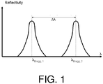
- such a fiber structure provides a basis for a sensor adapted for encoding pressure, preferably isotropic pressure, or a transverse load, i.e. a directional load perpendicular to the fiber axis, into the distance in wavelength ⁇ between the two reflection peaks of a Bragg grating written in such a fiber structure and as shown in Fig. 1.
- Fig. 1 illustrates the reflectivity as a function of wavelength and shows two Bragg wavelengths ⁇ Bragg1 and ⁇ Bragg2 .
- the sensitivity of the spectral distance between these two wavelengths to temperature or to pressure is referred to as "differential sensitivity".
- Fig. 2 shows a layout of a plurality of holes for the first type of a microstructured fiber structure according to a second preferred embodiment of the invention.
- guiding optical radiation refers for example, to the central holey structure transmitting about 99% or more, e.g. 99.99% of the light transferred along the optical fiber.
- a central region bordered by at least some of the holes of the central microstructure defines a transmission pathway for about 99% or more, e.g. 99.99% of the light transferred along the optical fiber.
- the zero differential temperature sensitivity for an FBG is achieved at a wavelength of 1.38 ⁇ m.
- the polarimetric pressure sensitivity at 1.55 ⁇ m comprises a value of -28 rad/MPa/m for 6 rings of holes and -38 rad/MPa/m for 9 rings of holes, respectively.
- the differential temperature sensitivity for an FBG at 1.55 ⁇ m comprises a value of -0.0056 pm/K.
- the zero differential temperature sensitivity is achieved at 1.7 ⁇ m.
- the polarimetric pressure sensitivity comprises a value of -36 rad/MPa/m at 1.55 ⁇ m.
- the value of the polarimetric pressure sensitivity is further increased to a level of about -45 rad/MPa/m by enlarging selected holes in the cladding, such as for 11 rings of air holes.
- the birefringence is similar to the first case and corresponds to a value of 7.6 x 10 -4 .
- the confinement losses and the bending losses show the same values as in the first case.
- the central microstructure 1 comprises three rows of air-holes.
- the row in the middle comprises a plurality of air-holes with a smaller diameter, which is adapted to make the fiber structure behave as single mode fiber. This is achieved by making the higher order modes much more lossy than the lower order modes.
- the two rows comprising a plurality of larger holes are adapted for determining the confinement losses.
- the macrostructure 3 replaces two or more of the air-holes in that row. It is preferred that the side-holes are arranged very close to the fiber core.
- a central region bordered by at least some of the holes of the central microstructure defines a transmission pathway for about 99% or more, e.g. 99.99% of the light transferred along the optical fiber.
- the macrostructure 3 is adapted for setting the phase modal birefringence of the fiber structure.
- the macrostructure 3 can also be adapted for setting the pressure sensitivity of the fiber structure.
- the macrostructure 3 replaces a part of the central microstructure 1.
- the shape of the side-holes in the macrostructure 3 comprises a shape corresponding to an elliptical, a rectangular, a circular or an even more exotic shape.
- the shape of the side-hole in the macrostructure 3 near the fiber core is chosen in such a way that the confinement losses are as low as possible.
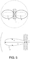
- the nearest distance from the edge of the macrostructure 3 to the fiber core, indicated as L3 and L2 in Fig. 5 , and the largest distance between two points on the edge of the macrostructure 3, indicated as L1, are adapted for determining the sensitivity level.
- the length L3 also determines the phase modal birefringence and the confinement losses and thus this length cannot be endlessly minimized.
- the size of L1 should be as large as possible, only limited by the fabrication technology and possibly by the splice conditions.
- the size of the length L2 is smaller than that of the length L1, although circular holes are also possible or even air-holes with L2 larger than L1.
- the length L2 shows an impact on the sensitivity level but this role is much less important in that of L1.
- Both presented fiber structures comprise a microstructure incorporating two functions:
- the part of the microstructure that lies close to the core region is adapted for contributing to the value of the phase modal birefringence B and, most importantly, to the differential temperature sensitivity of an FBG in the fiber.
- the outer part of the microstructure is designed to enhance the hydrostatic pressure sensitivity or the transversal load sensitivity of the fiber's birefringence and, at the same time, the differential hydrostatic pressure sensitivity or the transversal load sensitivity of an FBG in the fiber.
- the light is guided within this central region and the shape 16 of the transmitted beam is elongated in the same direction as the elongated shape of the central fiber region 15.
- the term "guiding optical radiation”, refers for example, to the central holey structure transmitting about 99% or more, e.g. 99.99% of the light transferred along the optical fiber.
- a central region bordered by at least some of the holes of the central microstructure defines a transmission pathway for about 99% or more, e.g. 99.99% of the light transferred along the optical fiber.
- Fig. 7a shows a cross-section through an optical fiber similar to that shown in Fig. 2 . It comprises a central microstructure region 1 and two large side holey structures 2 which are in this case microstructures.
- Fig. 7b shows a close-up of a region 15 about the core 10 which is mainly bounded by four of the holes 12 or the central microstructure. The two smaller holes 13, that influence the optical propagation modes, are further away and have less of an effect.
- the region 15 of the fiber around the core has a shape of a lozenge and is bounded mainly by the four holes 12 and has an elongated shape, namely the longer axis is horizontal in the figure (the slow axis). This shape has an effect on the light propagation in this central region 15.
- the MOF of Fig. 6 in practice contained a germanium-doped core (GeO 2 was 7.4 mol%) in a nearly elliptical shape, with major axis parallel to the vertical direction in Fig. 6 (slow axis).
- MOF of Fig. 7 had a shape of the core region (doped GeO 2 at 2.4 mol%) whereby the slow axis no longer corresponds to the vertical but to the horizontal axis of Fig. 6 .
- the doping level in these fibers lies close to an optimal value of 2.88 mol%, i.e. in the range 2 to 8 mol%. Hence a very low temperature sensitivity for the Bragg peak separation is obtained.
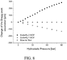
- the microstructure of embodiments of the present invention succeed in increasing the transverse sensitivity.
- the Butterfly 2 MOF has a pressure sensitivity that is more than twice that of Butterfly 1.
- Butterfly 1 has a negative coefficient with increasing pressure and
- Butterfly 2 has a positive coefficient while still maintaining the low temperature sensitivity in both cases.
- an aspect of the present invention is to control the sign of the coefficient of sensitivity to pressure depending upon the arrangement of the holes around the central region about the core and the shape of the fiber as bounded by these holes. The differences in this shape have been described above with reference to Fig. 6b and 7b .
- a central microstructure can be optimized (or designed) to choose the direction of the slow axis with respect to the side holey structures such as side microstructures or side macrostructures with the result of tailoring the sensitivity of the Bragg peak wavelengths that correspond to the slow and fast axes for an FBG in that fiber and/or to determine the sign of the differential Bragg peak sensitivity.
- side holey structures such as side microstructures or side macrostructures
- tailoring the sensitivity of the Bragg peak wavelengths that correspond to the slow and fast axes for an FBG in that fiber and/or to determine the sign of the differential Bragg peak sensitivity As described above fabricated fibers with both a negative and positive differential Bragg peak sensitivity have been described.
- the pressure sensing mechanism that stems from the asymmetric microstructure of embodiments of the present invention has the same orientation for both of the fibers of Fig. 6 and 7 .
Landscapes
- Physics & Mathematics (AREA)
- General Physics & Mathematics (AREA)
- Optics & Photonics (AREA)
- Optical Fibers, Optical Fiber Cores, And Optical Fiber Bundles (AREA)
- Measuring Fluid Pressure (AREA)
- Measuring Temperature Or Quantity Of Heat (AREA)
Claims (15)
- Faserstruktur, umfassend:ein Kern (10) und eine Verkleidung (4, 5, 6), die den Kern (10) umgibt;eine zentrale Mikrostruktur (1), die eine erste Vielzahl von Längsbohrungen umfasst, wobei die zentrale Mikrostruktur angepasst ist, um optische Strahlung zu führen und ein anfängliches Niveau an Doppelbrechung in dem Kern (10) über geometrische Doppelbrechung bereitzustellen;eine Seitenlochstruktur (2, 3), die eine zweite Vielzahl von Längslöchern umfasst, wobei die Seitenlochstruktur (2, 3) die zentrale Mikrostruktur (1) zumindest teilweise umgibt und angepasst ist, um eine vorbestimmte anisotrope Reaktion auf Druck bereitzustellen;ein dotierter Bereich in dem Kern (10) undeine auf Doppelbrechung ansprechende Einheit, die mindestens ein Faser-Bragg-Gitter umfasst, das zumindest teilweise in dem Kern (10) angeordnet ist, und dazu angepasst ist, Änderungen der Doppelbrechung im Kern zu codieren, die zu Änderungen des Bragg-Peak-Abstands Δλ zwischen zwei Reflexionsspitzen des wenigstens einen Bragg-Faser-Gitters führen, die in eine solche Faserstruktur geschrieben sind,und wobei der dotierte Bereich in dem Kern (10) ein vorbestimmtes Dotierungsniveau aufweist, das einen Unterschied im Wärmeausdehnungskoeffizienten zwischen dem dotierten Bereich in dem Kern (10) und der Verkleidung (4, 5, 6) verleiht und zur Bereitstellung einer vorbestimmten temperaturinduzierten Belastung und daher zur Bereitstellung einer vorbestimmten differentiellen Temperaturempfindlichkeit der Faserstruktur angepasst ist, wobei die differentielle Temperaturempfindlichkeit die Empfindlichkeit des Bragg-Peak-Abstands zwischen den Reflexionsspitzen gegenüber der Temperatur ist.
- Faserstruktur nach Anspruch 1, wobei die vorbestimmte differentielle Temperaturempfindlichkeit eine differentielle Temperaturempfindlichkeit von null ist und wobei der dotierte Bereich in dem Kern ein Dotierungsniveau von Germaniumdioxid innerhalb des Bereichs von 0 bis 35 Mol% umfasst.
- Faser nach Anspruch 2, wobei in dem dotierten Bereich im Kern (10) ein Dotierungsgrad von Germaniumdioxid im Bereich von 2 bis 7 Mol-% enthalten ist.
- Faserstruktur nach Anspruch 1, wobei die Seitenlochstruktur (2, 3) dazu angepasst ist, eine vorbestimmte anisotrope Reaktion auf isotropen Druck oder eine Querlast, das heißt eine gerichtete Last senkrecht zur Faserachse, bereitzustellen.
- Faserstruktur nach einem der vorstehenden Ansprüche, weiter umfassend eine Vielzahl von Gittern, die zumindest teilweise in dem Kern (10) angeordnet sind.
- Faserstruktur nach einem der Ansprüche 1 bis 5, wobei die zentrale Mikrostruktur (1) mindestens eine Reihe von Luftlöchern umfasst, vorzugsweise drei Reihen von Luftlöchern, die nebeneinander angeordnet sind, wobei der Durchmesser der mittleren Reihe kleiner ist als der Durchmesser der beiden äußeren Reihen.
- Faserstruktur nach Anspruch 6, wobei die zentrale Mikrostruktur (1) drei Reihen von Luftlöchern und umfasst, wobei die mittlere Reihe eine Vielzahl von Luftlöchern mit einem kleineren Durchmesser umfasst, die so angepasst sind, dass die Faser sich wie eine Einzelmodenfaser verhält, indem Modi höherer Ordnung viel verlustbehafteter gemacht werden als Modi niedrigerer Ordnung, und wobei die zwei äußeren Reihen, die der mittleren Reihe benachbart sind, größere Löcher umfassen, die eine hohe Begrenzung des Lichts in den Faserkern ermöglichen.
- Faserstruktur nach einem der vorstehenden Ansprüche, wobei die erste Vielzahl von Längslöchern derart angeordnet ist, dass ihre Längsachsen parallel zu der Längsachse des Kerns (10) sind.
- Faserstruktur nach einem der vorstehenden Ansprüche, wobei die erste und / oder die zweite Vielzahl von Längsbohrungen einen kreisförmigen Querschnitt, einen elliptischen Querschnitt, einen ringartigen Querschnitt oder einen sechseckigen Querschnitt umfasst / umfassen und zur Erhaltung einer vorbestimmten Doppelbrechung, einer vorbestimmten Druckempfindlichkeit, einer vorbestimmten Kraftempfindlichkeit, einer vorbestimmten Temperaturempfindlichkeit, eines vorbestimmten Verhältnisses von Druckempfindlichkeit und Temperaturempfindlichkeit und / oder einem vorbestimmten Verhältnis von Kraftempfindlichkeit und Temperaturempfindlichkeit angepasst ist / sind.
- Die Faserstruktur nach Anspruch 1, wobei die Seitenlochstruktur (2, 3) eine Makrostruktur (3) ist, wobei die Makrostruktur (3) mindestens zwei einander gegenüber angeordnete Seitenlöcher umfasst und dazu angepasst ist, die modale Doppelbrechung der Faserstruktur zu bestimmen.
- Faserstruktur nach Anspruch 10, wobei die Form der zwei Seitenlöcher angepasst ist, um Einschlussverluste zu reduzieren, und aus einer Form ausgewählt ist, die eine elliptische, eine rechteckige und/oder eine kreisförmige Form aufweist.
- Faserstruktur nach einem der Ansprüche 10 oder 11 oder nach Anspruch 1, wobei die Seitenlochstruktur (2, 3) eine Seitenmikrostruktur (2) ist, wobei die Verkleidung (4, 5, 6) eine innere Verkleidung und eine äußere Verkleidung umfasst, wobei die innere Verkleidung kreisförmige Merkmale und die äußere Verkleidung (5, 6) Merkmale bereitstellt, die sich von kreisförmigen Merkmalen unterscheiden.
- Faserstruktur nach einem der vorstehenden Ansprüche mit einer zentralen Mikrostruktur (1), die die Richtung der langsamen Achse der Glasfaser in Bezug auf die Seitenlochstruktur mit einer Empfindlichkeit der Bragg-Peak-Wellenlängen bestimmt, die den langsamen und schnellen Achsen für ein Faser-Bragg-Gitter (FBG) in dieser Faser entsprechen, wobei die Faserstruktur ein positives oder negatives Vorzeichen der differentiellen Bragg-Peak-Empfindlichkeit aufweist.
- Verfahren zur Verwendung einer Faserstruktur nach einem der Ansprüche 1 bis 13 mit Faser-Bragg-Gittern in mindestens einer der folgenden Sensoranwendungen:strukturelle Gesundheitsüberwachung von Verbundmaterialstrukturen, wie in Flugzeugstrukturen;Überwachen von Druck und Dehnung in Gegenwart von ionisierender Strahlung, wie in zivilen nuklearen Anwendungen, in militärischen Anwendungen, in Weltraumanwendungen und / oder in Anwendungen der Hochenergiephysik.
- Verfahren zur Herstellung einer Glasfaser, weiter umfassend die Schritte des Herstellens eines Kerns (10), der einen dotierten Bereich und eine den Kern (10) umgebende Umhüllung (4, 5, 6) umfasst, wobei eine zentrale Mikrostruktur (1) eine erste Vielzahl von Längslöchern umfasst, wobei die zentrale Mikrostruktur dafür eingerichtet ist, optische Strahlung zu führen und über geometrische Doppelbrechung eine Anfangsdoppelbrechung im Kern (10) bereitzustellen, eine Seitenlochstruktur (2, 3), die eine zweite Vielzahl von Längslöchern umfasst, wobei die Seitenlochstruktur (2, 3) die zentrale Mikrostruktur (1) zumindest teilweise umgibt und angepasst ist, um eine vorbestimmte anisotrope Reaktion auf Druck bereitzustellen und eine auf Doppelbrechung ansprechende Einheit, die mindestens ein Faser-Bragg-Gitter umfasst, das zumindest teilweise in dem Kern (10) angeordnet ist und dazu eingerichtet ist, eine Druckkraft oder eine Temperatur in eine Änderung der Doppelbrechung in dem Kern (10) umzuwandeln, resultierend in Änderungen des Bragg-Peak-Abstands Δλ zwischen zwei Reflexionsspitzen des mindestens einen Faser-Bragg-Gitters, die in solch einer Faserstruktur geschrieben sind, wobei das Herstellen einer zentralen Mikrostruktur (1) das Anpassen der Anordnung der Löcher der zentralen Mikrostruktur (1) umfasst und der Kern (10) zum Bestimmen der Richtung der langsamen Achse der Glasfaser in Bezug auf die löchrige Seitenstruktur mit dem Ergebnis des Anpassens der Empfindlichkeit der Bragg-Peak-Wellenlängen, die den langsamen und schnellen Achsen für das Faser-Bragg-Gitter in dieser Faser entsprechen und / oder um das Vorzeichen der differentiellen Bragg-Peak-Empfindlichkeit zu bestimmen, und wobei das Bereitstellen des dotierten Bereichs in dem Kern (10) das Bereitstellen eines dotierten Bereichs umfasst, der einen Dotierungspegel aufweist, der einen Unterschied im Wärmeausdehnungskoeffizienten zwischen dem dotierten Bereich in dem Kern und der Verkleidung (4, 5, 6) verleiht, und somit eine vorbestimmte temperaturinduzierte Spannung und somit eine vorbestimmte differentielle Temperaturempfindlichkeit der Faserstruktur bereitgestellt wird, wobei die differentielle Temperaturempfindlichkeit die Empfindlichkeit des Bragg-Peak-Abstands zwischen den Reflexionsspitzen gegenüber der Temperatur ist.
Priority Applications (1)
| Application Number | Priority Date | Filing Date | Title |
|---|---|---|---|
| EP10803451.3A EP2502102B1 (de) | 2009-11-19 | 2010-11-19 | Doppelbrechende mikrostrukturierte glasfaser für sensoranwendung |
Applications Claiming Priority (3)
| Application Number | Priority Date | Filing Date | Title |
|---|---|---|---|
| PCT/EP2009/065458 WO2011060817A1 (en) | 2009-11-19 | 2009-11-19 | Optical fiber structure for sensors |
| EP10803451.3A EP2502102B1 (de) | 2009-11-19 | 2010-11-19 | Doppelbrechende mikrostrukturierte glasfaser für sensoranwendung |
| PCT/EP2010/067862 WO2011061309A1 (en) | 2009-11-19 | 2010-11-19 | Birefringent micro-structured optical fiber for sensor application |
Publications (2)
| Publication Number | Publication Date |
|---|---|
| EP2502102A1 EP2502102A1 (de) | 2012-09-26 |
| EP2502102B1 true EP2502102B1 (de) | 2018-09-05 |
Family
ID=46690908
Family Applications (1)
| Application Number | Title | Priority Date | Filing Date |
|---|---|---|---|
| EP10803451.3A Active EP2502102B1 (de) | 2009-11-19 | 2010-11-19 | Doppelbrechende mikrostrukturierte glasfaser für sensoranwendung |
Country Status (1)
| Country | Link |
|---|---|
| EP (1) | EP2502102B1 (de) |
Cited By (1)
| Publication number | Priority date | Publication date | Assignee | Title |
|---|---|---|---|---|
| WO2020136428A1 (es) * | 2018-12-28 | 2020-07-02 | Instituto Tecnologico Metropolitano | Conversor modal sintonizable |
Families Citing this family (3)
| Publication number | Priority date | Publication date | Assignee | Title |
|---|---|---|---|---|
| GB2542855B (en) | 2015-10-02 | 2017-10-11 | Smart Fibres Ltd | Monitoring probe |
| US10436655B2 (en) | 2017-07-14 | 2019-10-08 | Saudi Arabian Oil Company | Fluorophore enhanced multidimensional photonic sensors |
| EP3546697B1 (de) | 2018-03-30 | 2021-11-03 | FBGS Technologies GmbH | Optisches abtastsystem |
-
2010
- 2010-11-19 EP EP10803451.3A patent/EP2502102B1/de active Active
Cited By (1)
| Publication number | Priority date | Publication date | Assignee | Title |
|---|---|---|---|---|
| WO2020136428A1 (es) * | 2018-12-28 | 2020-07-02 | Instituto Tecnologico Metropolitano | Conversor modal sintonizable |
Also Published As
| Publication number | Publication date |
|---|---|
| EP2502102A1 (de) | 2012-09-26 |
Similar Documents
| Publication | Publication Date | Title |
|---|---|---|
| US8958676B2 (en) | Birefringent micro-structured optical fiber for sensor application | |
| EP1991894B1 (de) | Photonische merhkern-bandlückenfaser mit kopplung zwischen den kernen | |
| EP3163339B1 (de) | Mehradrige polarisationserhaltende faser | |
| US7174078B2 (en) | Dual core photonic crystal fibers (PCF) with special dispersion properties | |
| US6982996B1 (en) | Large diameter optical waveguide, grating, and laser | |
| Shao et al. | Directional bend sensor based on re-grown tilted fiber Bragg grating | |
| US9971087B2 (en) | High-birefringence hollow-core fibers and techniques for making same | |
| EP2749919A1 (de) | Mehrkernfaser und verfahren zur positionierung eines mehrkernfaserkerns | |
| EP3025175B1 (de) | Einzelmodus-verstärkung einer beschichtung in doppelt beschichteten aktiven fasern | |
| Wang et al. | CO 2-laser-induced long period fiber gratings in few mode fibers | |
| Wang et al. | Sensing properties of fiber Bragg gratings in small-core Ge-doped photonic crystal fibers | |
| EP2502102A1 (de) | Doppelbrechende mikrostrukturierte optische faser für sensoranwendung | |
| US12270717B2 (en) | Optical fiber pressure sensor and method of sensing thereof | |
| Nasilowski et al. | Birefringent photonic crystal fiber as a multi-parameter sensor | |
| Xin et al. | Sensing Characteristics of Side‐Hole Fiber‐Based Long‐Period Grating | |
| US11156769B2 (en) | Polarization-maintaining fiber device supporting propagation in large mode field diameters | |
| CN103091773A (zh) | 1.31微米和1.55微米双波段可调谐光子晶体光纤滤波器 | |
| Rao | Novel mechanical fiber optic sensors based on long-period fiber gratings written by high-frequency CO2 laser pulses | |
| Wang et al. | UV-laser-inscribed fiber Bragg gratings in photonic crystal fibers and sensing applications | |
| Chen et al. | The inner cladding mode in a photonic crystal fiber for temperature-and refractive index-independent strain sensing applications | |
| Torres-Peiró et al. | Cutoff properties of liquid-filled Ge-doped microstructured fibers | |
| Kim et al. | Experimental characterization of elliptical hollow-core photonic bandgap fiber at wavelengths within the bandgap | |
| Wang et al. | Guided properties and applications of photonic bandgap fibers | |
| Nasilowski | Fiber Bragg Grating Sensors in Microstructured Optical Fibers | |
| Anuszkiewicz et al. | Rocking filter in microstructured birefringent fiber for hydrostatic pressure measurements |
Legal Events
| Date | Code | Title | Description |
|---|---|---|---|
| PUAI | Public reference made under article 153(3) epc to a published international application that has entered the european phase |
Free format text: ORIGINAL CODE: 0009012 |
|
| 17P | Request for examination filed |
Effective date: 20120604 |
|
| AK | Designated contracting states |
Kind code of ref document: A1 Designated state(s): AL AT BE BG CH CY CZ DE DK EE ES FI FR GB GR HR HU IE IS IT LI LT LU LV MC MK MT NL NO PL PT RO RS SE SI SK SM TR |
|
| DAX | Request for extension of the european patent (deleted) | ||
| 17Q | First examination report despatched |
Effective date: 20150909 |
|
| RIC1 | Information provided on ipc code assigned before grant |
Ipc: G01L 11/02 20060101ALI20170810BHEP Ipc: G01D 5/353 20060101ALI20170810BHEP Ipc: G02B 6/02 20060101AFI20170810BHEP Ipc: G02B 6/10 20060101ALN20170810BHEP |
|
| GRAP | Despatch of communication of intention to grant a patent |
Free format text: ORIGINAL CODE: EPIDOSNIGR1 |
|
| INTG | Intention to grant announced |
Effective date: 20170927 |
|
| RIC1 | Information provided on ipc code assigned before grant |
Ipc: G01L 11/02 20060101ALI20170918BHEP Ipc: G01D 5/353 20060101ALI20170918BHEP Ipc: G02B 6/02 20060101AFI20170918BHEP Ipc: G02B 6/10 20060101ALN20170918BHEP |
|
| GRAS | Grant fee paid |
Free format text: ORIGINAL CODE: EPIDOSNIGR3 |
|
| RIN1 | Information on inventor provided before grant (corrected) |
Inventor name: URBANCZYK, WACLAW Inventor name: POTURAJ, KRZYSZTOF, GRZEGORZ Inventor name: GEERNAERT, THOMAS Inventor name: BERGHMANS, FRANCIS Inventor name: WOJCIK, JAN JOZEF Inventor name: OLSZEWSKI, JACEK MAREK Inventor name: MERGO, PAWEL Inventor name: THIENPONT, HUGO Inventor name: NASILOWSKI, TOMASZ Inventor name: MARTYNKIEN, TADEUSZ Inventor name: MAKARA, MARIUSZ |
|
| GRAA | (expected) grant |
Free format text: ORIGINAL CODE: 0009210 |
|
| AK | Designated contracting states |
Kind code of ref document: B1 Designated state(s): AL AT BE BG CH CY CZ DE DK EE ES FI FR GB GR HR HU IE IS IT LI LT LU LV MC MK MT NL NO PL PT RO RS SE SI SK SM TR |
|
| RAP1 | Party data changed (applicant data changed or rights of an application transferred) |
Owner name: POLITECHNIKA WROCLAWSKA (WROCLAW UNIVERSITY OF SCI Owner name: UNIWERSYTET MARII CURIE SKLODOWSKIEJ Owner name: VRIJE UNIVERSITEIT BRUSSEL |
|
| REG | Reference to a national code |
Ref country code: GB Ref legal event code: FG4D |
|
| REG | Reference to a national code |
Ref country code: CH Ref legal event code: EP |
|
| REG | Reference to a national code |
Ref country code: AT Ref legal event code: REF Ref document number: 1038489 Country of ref document: AT Kind code of ref document: T Effective date: 20180915 |
|
| REG | Reference to a national code |
Ref country code: IE Ref legal event code: FG4D |
|
| REG | Reference to a national code |
Ref country code: DE Ref legal event code: R096 Ref document number: 602010053391 Country of ref document: DE |
|
| REG | Reference to a national code |
Ref country code: NL Ref legal event code: FP |
|
| REG | Reference to a national code |
Ref country code: LT Ref legal event code: MG4D |
|
| PG25 | Lapsed in a contracting state [announced via postgrant information from national office to epo] |
Ref country code: GR Free format text: LAPSE BECAUSE OF FAILURE TO SUBMIT A TRANSLATION OF THE DESCRIPTION OR TO PAY THE FEE WITHIN THE PRESCRIBED TIME-LIMIT Effective date: 20181206 Ref country code: BG Free format text: LAPSE BECAUSE OF FAILURE TO SUBMIT A TRANSLATION OF THE DESCRIPTION OR TO PAY THE FEE WITHIN THE PRESCRIBED TIME-LIMIT Effective date: 20181205 Ref country code: FI Free format text: LAPSE BECAUSE OF FAILURE TO SUBMIT A TRANSLATION OF THE DESCRIPTION OR TO PAY THE FEE WITHIN THE PRESCRIBED TIME-LIMIT Effective date: 20180905 Ref country code: LT Free format text: LAPSE BECAUSE OF FAILURE TO SUBMIT A TRANSLATION OF THE DESCRIPTION OR TO PAY THE FEE WITHIN THE PRESCRIBED TIME-LIMIT Effective date: 20180905 Ref country code: RS Free format text: LAPSE BECAUSE OF FAILURE TO SUBMIT A TRANSLATION OF THE DESCRIPTION OR TO PAY THE FEE WITHIN THE PRESCRIBED TIME-LIMIT Effective date: 20180905 Ref country code: SE Free format text: LAPSE BECAUSE OF FAILURE TO SUBMIT A TRANSLATION OF THE DESCRIPTION OR TO PAY THE FEE WITHIN THE PRESCRIBED TIME-LIMIT Effective date: 20180905 |
|
| REG | Reference to a national code |
Ref country code: NO Ref legal event code: T2 Effective date: 20180905 |
|
| REG | Reference to a national code |
Ref country code: AT Ref legal event code: MK05 Ref document number: 1038489 Country of ref document: AT Kind code of ref document: T Effective date: 20180905 |
|
| PG25 | Lapsed in a contracting state [announced via postgrant information from national office to epo] |
Ref country code: AL Free format text: LAPSE BECAUSE OF FAILURE TO SUBMIT A TRANSLATION OF THE DESCRIPTION OR TO PAY THE FEE WITHIN THE PRESCRIBED TIME-LIMIT Effective date: 20180905 Ref country code: HR Free format text: LAPSE BECAUSE OF FAILURE TO SUBMIT A TRANSLATION OF THE DESCRIPTION OR TO PAY THE FEE WITHIN THE PRESCRIBED TIME-LIMIT Effective date: 20180905 Ref country code: LV Free format text: LAPSE BECAUSE OF FAILURE TO SUBMIT A TRANSLATION OF THE DESCRIPTION OR TO PAY THE FEE WITHIN THE PRESCRIBED TIME-LIMIT Effective date: 20180905 |
|
| PG25 | Lapsed in a contracting state [announced via postgrant information from national office to epo] |
Ref country code: AT Free format text: LAPSE BECAUSE OF FAILURE TO SUBMIT A TRANSLATION OF THE DESCRIPTION OR TO PAY THE FEE WITHIN THE PRESCRIBED TIME-LIMIT Effective date: 20180905 Ref country code: EE Free format text: LAPSE BECAUSE OF FAILURE TO SUBMIT A TRANSLATION OF THE DESCRIPTION OR TO PAY THE FEE WITHIN THE PRESCRIBED TIME-LIMIT Effective date: 20180905 Ref country code: IS Free format text: LAPSE BECAUSE OF FAILURE TO SUBMIT A TRANSLATION OF THE DESCRIPTION OR TO PAY THE FEE WITHIN THE PRESCRIBED TIME-LIMIT Effective date: 20190105 Ref country code: PL Free format text: LAPSE BECAUSE OF FAILURE TO SUBMIT A TRANSLATION OF THE DESCRIPTION OR TO PAY THE FEE WITHIN THE PRESCRIBED TIME-LIMIT Effective date: 20180905 Ref country code: CZ Free format text: LAPSE BECAUSE OF FAILURE TO SUBMIT A TRANSLATION OF THE DESCRIPTION OR TO PAY THE FEE WITHIN THE PRESCRIBED TIME-LIMIT Effective date: 20180905 Ref country code: IT Free format text: LAPSE BECAUSE OF FAILURE TO SUBMIT A TRANSLATION OF THE DESCRIPTION OR TO PAY THE FEE WITHIN THE PRESCRIBED TIME-LIMIT Effective date: 20180905 Ref country code: ES Free format text: LAPSE BECAUSE OF FAILURE TO SUBMIT A TRANSLATION OF THE DESCRIPTION OR TO PAY THE FEE WITHIN THE PRESCRIBED TIME-LIMIT Effective date: 20180905 Ref country code: RO Free format text: LAPSE BECAUSE OF FAILURE TO SUBMIT A TRANSLATION OF THE DESCRIPTION OR TO PAY THE FEE WITHIN THE PRESCRIBED TIME-LIMIT Effective date: 20180905 |
|
| PG25 | Lapsed in a contracting state [announced via postgrant information from national office to epo] |
Ref country code: SM Free format text: LAPSE BECAUSE OF FAILURE TO SUBMIT A TRANSLATION OF THE DESCRIPTION OR TO PAY THE FEE WITHIN THE PRESCRIBED TIME-LIMIT Effective date: 20180905 Ref country code: PT Free format text: LAPSE BECAUSE OF FAILURE TO SUBMIT A TRANSLATION OF THE DESCRIPTION OR TO PAY THE FEE WITHIN THE PRESCRIBED TIME-LIMIT Effective date: 20190105 Ref country code: SK Free format text: LAPSE BECAUSE OF FAILURE TO SUBMIT A TRANSLATION OF THE DESCRIPTION OR TO PAY THE FEE WITHIN THE PRESCRIBED TIME-LIMIT Effective date: 20180905 |
|
| REG | Reference to a national code |
Ref country code: DE Ref legal event code: R097 Ref document number: 602010053391 Country of ref document: DE |
|
| REG | Reference to a national code |
Ref country code: CH Ref legal event code: PL |
|
| PLBE | No opposition filed within time limit |
Free format text: ORIGINAL CODE: 0009261 |
|
| STAA | Information on the status of an ep patent application or granted ep patent |
Free format text: STATUS: NO OPPOSITION FILED WITHIN TIME LIMIT |
|
| PG25 | Lapsed in a contracting state [announced via postgrant information from national office to epo] |
Ref country code: DK Free format text: LAPSE BECAUSE OF FAILURE TO SUBMIT A TRANSLATION OF THE DESCRIPTION OR TO PAY THE FEE WITHIN THE PRESCRIBED TIME-LIMIT Effective date: 20180905 Ref country code: MC Free format text: LAPSE BECAUSE OF FAILURE TO SUBMIT A TRANSLATION OF THE DESCRIPTION OR TO PAY THE FEE WITHIN THE PRESCRIBED TIME-LIMIT Effective date: 20180905 Ref country code: LU Free format text: LAPSE BECAUSE OF NON-PAYMENT OF DUE FEES Effective date: 20181119 |
|
| 26N | No opposition filed |
Effective date: 20190606 |
|
| PG25 | Lapsed in a contracting state [announced via postgrant information from national office to epo] |
Ref country code: SI Free format text: LAPSE BECAUSE OF FAILURE TO SUBMIT A TRANSLATION OF THE DESCRIPTION OR TO PAY THE FEE WITHIN THE PRESCRIBED TIME-LIMIT Effective date: 20180905 Ref country code: LI Free format text: LAPSE BECAUSE OF NON-PAYMENT OF DUE FEES Effective date: 20181130 Ref country code: CH Free format text: LAPSE BECAUSE OF NON-PAYMENT OF DUE FEES Effective date: 20181130 |
|
| PG25 | Lapsed in a contracting state [announced via postgrant information from national office to epo] |
Ref country code: MT Free format text: LAPSE BECAUSE OF NON-PAYMENT OF DUE FEES Effective date: 20181119 |
|
| PG25 | Lapsed in a contracting state [announced via postgrant information from national office to epo] |
Ref country code: TR Free format text: LAPSE BECAUSE OF FAILURE TO SUBMIT A TRANSLATION OF THE DESCRIPTION OR TO PAY THE FEE WITHIN THE PRESCRIBED TIME-LIMIT Effective date: 20180905 |
|
| PG25 | Lapsed in a contracting state [announced via postgrant information from national office to epo] |
Ref country code: MK Free format text: LAPSE BECAUSE OF NON-PAYMENT OF DUE FEES Effective date: 20180905 Ref country code: HU Free format text: LAPSE BECAUSE OF FAILURE TO SUBMIT A TRANSLATION OF THE DESCRIPTION OR TO PAY THE FEE WITHIN THE PRESCRIBED TIME-LIMIT; INVALID AB INITIO Effective date: 20101119 Ref country code: CY Free format text: LAPSE BECAUSE OF FAILURE TO SUBMIT A TRANSLATION OF THE DESCRIPTION OR TO PAY THE FEE WITHIN THE PRESCRIBED TIME-LIMIT Effective date: 20180905 |
|
| P01 | Opt-out of the competence of the unified patent court (upc) registered |
Effective date: 20230526 |
|
| PGFP | Annual fee paid to national office [announced via postgrant information from national office to epo] |
Ref country code: NL Payment date: 20251119 Year of fee payment: 16 |
|
| PGFP | Annual fee paid to national office [announced via postgrant information from national office to epo] |
Ref country code: DE Payment date: 20251119 Year of fee payment: 16 |
|
| PGFP | Annual fee paid to national office [announced via postgrant information from national office to epo] |
Ref country code: GB Payment date: 20251121 Year of fee payment: 16 |
|
| PGFP | Annual fee paid to national office [announced via postgrant information from national office to epo] |
Ref country code: NO Payment date: 20251125 Year of fee payment: 16 |
|
| PGFP | Annual fee paid to national office [announced via postgrant information from national office to epo] |
Ref country code: FR Payment date: 20251125 Year of fee payment: 16 |
|
| PGFP | Annual fee paid to national office [announced via postgrant information from national office to epo] |
Ref country code: BE Payment date: 20251119 Year of fee payment: 16 |
|
| PGFP | Annual fee paid to national office [announced via postgrant information from national office to epo] |
Ref country code: IE Payment date: 20251121 Year of fee payment: 16 |