EP2501998B1 - Commercial kitchen exhaust system - Google Patents
Commercial kitchen exhaust system Download PDFInfo
- Publication number
- EP2501998B1 EP2501998B1 EP10779373.9A EP10779373A EP2501998B1 EP 2501998 B1 EP2501998 B1 EP 2501998B1 EP 10779373 A EP10779373 A EP 10779373A EP 2501998 B1 EP2501998 B1 EP 2501998B1
- Authority
- EP
- European Patent Office
- Prior art keywords
- exhaust system
- hood
- exhaust
- filter unit
- flow
- Prior art date
- Legal status (The legal status is an assumption and is not a legal conclusion. Google has not performed a legal analysis and makes no representation as to the accuracy of the status listed.)
- Active
Links
Images





Classifications
-
- F—MECHANICAL ENGINEERING; LIGHTING; HEATING; WEAPONS; BLASTING
- F24—HEATING; RANGES; VENTILATING
- F24C—DOMESTIC STOVES OR RANGES ; DETAILS OF DOMESTIC STOVES OR RANGES, OF GENERAL APPLICATION
- F24C15/00—Details
- F24C15/20—Removing cooking fumes
- F24C15/2028—Removing cooking fumes using an air curtain
-
- F—MECHANICAL ENGINEERING; LIGHTING; HEATING; WEAPONS; BLASTING
- F24—HEATING; RANGES; VENTILATING
- F24C—DOMESTIC STOVES OR RANGES ; DETAILS OF DOMESTIC STOVES OR RANGES, OF GENERAL APPLICATION
- F24C15/00—Details
- F24C15/20—Removing cooking fumes
-
- F—MECHANICAL ENGINEERING; LIGHTING; HEATING; WEAPONS; BLASTING
- F24—HEATING; RANGES; VENTILATING
- F24C—DOMESTIC STOVES OR RANGES ; DETAILS OF DOMESTIC STOVES OR RANGES, OF GENERAL APPLICATION
- F24C15/00—Details
- F24C15/20—Removing cooking fumes
- F24C15/2042—Devices for removing cooking fumes structurally associated with a cooking range e.g. downdraft
Definitions
- the present invention relates generally to exhaust hoods utilized in kitchens of commercial establishments such as restaurants and cafeterias and, more particularly, to an exhaust hood structure and arrangement that effectively removes a thermal plume generated by commercial cooking equipment with a reduced exhaust volume.
- Kitchen ventilator exhaust hoods have long been provided for the purpose of exhausting steam, smoke, heat and effluent particulates such as grease (e.g., generally referred to as the thermal plume) that are produced by cooking appliances in the commercial cooking environment.
- a variety of exhaust hood configurations are known.
- a typical hood system configuration is depicted in Fig. 1 , where an apron 10 of the hood 12 forces the buoyancy driven exhaust flows to change direction resulting in lateral flows proximate the filter aperture such that increased exhaust airflow rates are required to maintain capture and containment.
- the filter aperture 14 and filter unit 16 are angled at approximately 45 degrees or greater to vertical, and the thermal plume and replacement air are shown respectively by flows 18 and 20.
- the replacement air flow includes a significant component that travels between the rear side of the commercial cooking appliances 22 (e.g., ranges, broilers, frying apparatus etc.) and the building wall structure 24.
- existing hood systems typically draw off and expel an undesirably large volume of air.
- An exhaust system may include a hood structure having one or more of (i) an exhaust flow infeed surface extending downward from a lower end of the filter unit that helps to feed the thermal plume toward the filter unit, (ii) a bypass flow transition surface extending upward from the upper end of the filter unit and then forward to aid bypass flow in circulating back toward the filter aperture and (iii) a front wall structure that includes a downwardly extending wall portion with a chamfered and/or curved transition portion at its lower end and a rearwardly extending wall portion.
- a commercial cooking equipment exhaust system for exhausting thermal plume produced by cooking operations includes a hood structure with a downwardly facing inlet opening, a filter aperture positioned within the hood structure with a filter unit positioned therein.
- An exhaust flow infeed surface extends downward from a lower end of the filter unit, the exhaust flow infeed surface oriented at an angle of no more than forty degrees relative to a laterally extending plane that is arranged perpendicular to an inlet face of the filter unit.
- the exhaust flow infeed surface includes a minor portion that turns rearward from the top of the major portion and terminates proximate a lower end of the filter unit.
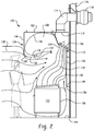
- a side elevation of a commercial cooking equipment exhaust system 100 is shown.
- the system includes a hood structure 102 having a downwardly facing inlet opening 103 and a filter aperture 104 with a filter unit 106 positioned therein.
- the filter unit may typically be formed by a baffle-type filter, but other types of filter structures could be used.
- the filter aperture 104 and filter unit 106 are located toward the rear side of the hood structure 102. Upstream and forward of the filter aperture the hood structure 102 defines a containment and capture volume 108 for flows that bypass the filter.
- the hood structure Downstream of the filter aperture the hood structure may include a grease gutter 110 and an exhaust outlet 112 that connects with ductwork 114 that, in the illustrated embodiment, passes through a building wall structure 116, and has an associated exhaust fan 118. The operation of the exhaust fan pulls air through the filter unit 106.
- additional baffling or other structure e.g., spray cleaning systems and/or fire suppression systems
- the primary components of the hood structure may, typically, be manufactured of sheet metal type material, such as stainless steel.
- the hood structure may typically be mounted to and supported by the building wall structure and/or a ceiling structure of the installation site.
- the illustrated hood structure includes an exhaust flow infeed surface 120 extending downward from a lower end of the filter unit 106 that helps to feed the thermal plume toward the filter unit, a bypass flow transition surface 122 extending upward from the upper end of the filter unit 106 and then forward to aid bypass flow in circulating back toward the filter aperture and a front wall structure 124 that includes a downwardly extending wall portion 126 with a chamfered and/or curved transition portion 128 at its lower end and a rearwardly extending wall portion 130 that promotes a horizontal component in replacement air flow.
- the replacement air flow is represented by flow 132
- thermal plume flow is represented by flow 134
- filter bypass flow is represented by flow 136.
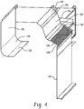
- the exhaust flow infeed surface includes a major portion 140 that is arranged substantially vertically.
- the inlet face 142 of the filter unit is arranged at an angle ⁇ relative to vertical of at least fifty degrees, and preferably at least fifty-five degrees or more preferably at least sixty degrees.
- An upper, minor portion 144 of the exhaust flow infeed surface turns rearward from the top of the major portion 140 and terminates proximate a lower end of the filter unit 106.
- This arrangement results in an exhaust flow infeed surface that is oriented at an angle ⁇ of no more than forty-five degrees, and preferably no more than forty degrees, and more preferably no more than thirty-five degrees (e.g., thirty degrees or less) relative to a laterally extending plane 146 (extending into and out of the page in the side view of Fig. 3 ) that is arranged perpendicular to the inlet face 142 of the filter unit, thereby resulting in a plume flow that moves toward and into the inlet filter as a similar angle.
- the plume flow is thus directed into the filter unit without any required change of direction in the vicinity of the hood structure, which change of direction would tend to interfere with a free flow into and through the filter unit.
- the more perpendicular the inflow is to the inlet face of the filter the greater the free flow into and through the filter unit.
- the exhaust flow infeed surface extends downward below the hood and terminates with its a lower end at a height that is proximate a height of the cooking surface 150 of the commercial cooking appliance 152. Typically, this height should be at least 72 cm (30 inches) above the floor (e.g., between 81.3 and 111.8 cm [between 32 and 44 inches] above the floor 154) as dictated by equipment heights and associated utility hook ups.
- the exhaust flow infeed surface 120 is offset outward from the building wall structure 116, pinching off and reducing the size of the flow area 156 for replacement air that travels beneath the appliance and upward along the rear side 158 of the appliance.
- the surface 120 may be offset from the wall surface by a distance of at least 7.6 cm (3 inches) (e.g. between 7.6 and 40.6 cm [3 and 16 inches]) and the rear side 158 of the appliance may be offset from the wall surface by at least 10.2 cm (4 inches) (e.g. between 10.2 and 43.2 cm [between 4 and 17 inches]).
- the exhaust flow infeed surface 120 may be formed by, for example, a box-like structure formed of sheet metal that is enclosed at the sides and the bottom (e.g., the space behind the surface is not used for the flow of air into the hood or back into the kitchen).
- the bypass flow transition surface 122 extends upward from the upper end of the filter unit and then forward toward the front of the hood structure to aid bypass flow in circulating back toward the filter aperture.
- the volume of the thermal plume can vary significantly and, at peak thermal plume production, the flow through the filter unit is not sufficient to draw in the entire thermal plume volume, which results in a bypass flow 136 past the filter unit, which is allowed to accumulate in the front of the hood until plume generation slows.
- the surface 122 includes a first portion 160 that extends away from the upper end of the filter unit and generally parallel to the inlet face of the filter unit, a second portion 162 that turns (e.g., via curving and/or chamfering) upward to a third, generally planar portion 164 that is angled upward relative to the plane in which the inlet face of the filter unit lies, followed by a fourth portion 166 that turns (e.g., via curving and/or chamfering) forward to a fifth portion 168 that intersects with the top wall 170 of the hood structure.
- the surface 122 which is multi faceted, and shaped to create a convex radius shape, serves to accelerate the flow bypassing the filter towards the top panel of the hood and then to the front of the hood.
- the front 124 of the hood structure includes downwardly extending wall portion 126 with a chamfered and/or curved transition portion 128 at its lower end and a rearwardly extending wall portion 130 that is generally horizontally.
- the front wall structure provides an interior chamfered and/or curved transition surface 172 that aids in turning the bypass flow back toward the filter.
- the horizontal extent 130 also helps to direct the bypass flow back toward the filter.
- the upper forward corner could include a curved or chamfered component 174 as well.
- the front wall structure also provides an exterior chamfered and/or curved transition surface 174 that promotes a horizontal velocity component in the replacement air flow proximate the lower edge of the hood.
- a radius or chamfer 128 of at least 7.6 (3 inches) e.g. between 10.2 and 20.3 cm [between 4 and 8 inches]
- a flat 130 having a depthwise length of at least 7.6 (3 inches) e.g.
- the return arrangement formed by portions 128 and 130 also serves to partially close down the opening of the bottom of the hood increasing velocities into the hood aperture while still allowing a large hood canopy volume for capture of bypass flows.
- An upwardly angled lip 131 is located at the end of flat 130.
- the lip preferably has is at least 2.5 cm (1 inch) in length and may extend at an angle that is at least forty-five degrees relative to horizontal (e.g., sixty degrees).
- the lip structure aids in holding grease within the hood and also aids in producing a pressure drop that tends to pull air flow off of the front edge of the hood.
- FIG. 5 is a thermal representation
- Fig. 6 is an air flow representation.
- the replacement air flow helps maintain a thermal boundary 182 to aid in keeping the thermal plume 184 beneath the hood and out of the work area of cooking personnel.
- the thermal boundary 182 is generally a turbulent boundary with a temperature gradient across some distance rather than the ideal line of demarcation shown in Fig. 5 .
- the curve or chamfer at the front edge of the hood applies an inward pressure at the front edge area that helps contain the plume.
- the diffuser feeds in replacement air at a velocity of between 22.9 and 45.7 meter per minute (75 and 150 feet per minute) and at a volumetric flow rate of between 2.8 and 8.4 cubic meter per minute per lineal meter (between 30 and 90 cubic feet per minute per lineal foot) of diffuser width, where the diffuser width is measured along the front of the hood structure (i.e., into the page in Fig. 5 ).
- the inflow of air via the diffuser 180 may be set at a volume that is between about 25% and 35% of the volume of air that passes through the hood.
- the thermal boundary effect will be most effective when replacement air output by the diffuser has a temperature that is lower than an ambient temperature of the location at which the exhaust system is installed (e.g., at least one degree lower).
- the replacement air may, for example, be drawn from a conditioned space of the building that is in a different location (e.g., a different room, such as a dining area) than the exhaust system. Controlled dampening of tempered air could also be used. Air removed from the exhaust system location (e.g., the kitchen) for this effect would preferably be taken from the ground level where temperatures are cooler, or even ducted in from areas inside the building where the temperature are less than the kitchen ambient.
- the application of the diffuser at ambient or below temperature, and being run at controlled velocity and volumetric flow, will also starve the middle of the hood for replacement air which it will get from the sides of the hood strengthening them as well in the process.
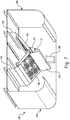
- FIG. 7 A further embodiment of an exhaust system, in the form of a two-sided island hood structure 190, is shown in Fig. 7 .
- Separate exhaust flow infeed surfaces 192 and 194 feed separate filter units 196 and 198, and bypass transition surfaces 200 and 202 (e.g., which may be shaped as described above) are provided at the upper side of each filter unit.
- the illustrated surfaces 192 and 194 are fully contained within the height of the hood.
- each wall structure 204 and 206 represents a front wall structure (e.g., relative to the location of the corresponding filter unit) and each front wall structure includes downward, transitional and rearward portions similar to those described above.
- a hanging grease capture bucket/container 208 to receive grease from the grease gutter 210.
- the container 208 is located at least two feet from the lateral edge of the hood structure.
- a back shelf hood embodiment is shown in which the hood structure 220 is located at a lower elevation from the cooking equipment 222.
- a rear exhaust flow infeed surface 224 is provided and is arranged to restrict flow up behind the equipment it draws more replacement air from the front.
- the illustrated surface 224 terminates proximate the cooking surface (e.g., between 81.3 and 111.8 cm [between 32 and 44 inches] above the floor).
- transition surface 228 similar to transition surface 122
- the front edge of the hood structure includes a vertical wall portion 230, a chamfer or curved portion 232 and a lip 234 lip structure that in combination promotes a flow or replacement air back toward the filter aperture while also closes down the hood aperture increasing the relative entrance velocities.
- no horizontal leg is provided, such that the rearwardly extending structure angles downwardly.
- the front edge could include a horizontal extent such as segment 130 of the above embodiments.
Landscapes
- Engineering & Computer Science (AREA)
- Chemical & Material Sciences (AREA)
- Combustion & Propulsion (AREA)
- Mechanical Engineering (AREA)
- General Engineering & Computer Science (AREA)
- Ventilation (AREA)
Description
- The present invention relates generally to exhaust hoods utilized in kitchens of commercial establishments such as restaurants and cafeterias and, more particularly, to an exhaust hood structure and arrangement that effectively removes a thermal plume generated by commercial cooking equipment with a reduced exhaust volume.
- Kitchen ventilator exhaust hoods have long been provided for the purpose of exhausting steam, smoke, heat and effluent particulates such as grease (e.g., generally referred to as the thermal plume) that are produced by cooking appliances in the commercial cooking environment. A variety of exhaust hood configurations are known. A typical hood system configuration is depicted in
Fig. 1 , where anapron 10 of thehood 12 forces the buoyancy driven exhaust flows to change direction resulting in lateral flows proximate the filter aperture such that increased exhaust airflow rates are required to maintain capture and containment. Thefilter aperture 14 andfilter unit 16 are angled at approximately 45 degrees or greater to vertical, and the thermal plume and replacement air are shown respectively byflows building wall structure 24. In order to assure the capture of substantially all of the thermal plume, existing hood systems typically draw off and expel an undesirably large volume of air. - Accordingly, in view of the ever increasing demand and importance of energy efficiency, improved systems are sought to capture and contain substantially all of the thermal plume while reducing the volume of air drawn through the hood.
- An exhaust system may include a hood structure having one or more of (i) an exhaust flow infeed surface extending downward from a lower end of the filter unit that helps to feed the thermal plume toward the filter unit, (ii) a bypass flow transition surface extending upward from the upper end of the filter unit and then forward to aid bypass flow in circulating back toward the filter aperture and (iii) a front wall structure that includes a downwardly extending wall portion with a chamfered and/or curved transition portion at its lower end and a rearwardly extending wall portion.
- According to the present invention, a commercial cooking equipment exhaust system for exhausting thermal plume produced by cooking operations includes a hood structure with a downwardly facing inlet opening, a filter aperture positioned within the hood structure with a filter unit positioned therein. An exhaust flow infeed surface extends downward from a lower end of the filter unit, the exhaust flow infeed surface oriented at an angle of no more than forty degrees relative to a laterally extending plane that is arranged perpendicular to an inlet face of the filter unit.
- The exhaust flow infeed surface includes a minor portion that turns rearward from the top of the major portion and terminates proximate a lower end of the filter unit.
-
-
Fig. 1 is a side elevation of a prior art exhaust hood system; -
Fig. 2 is a side elevation of one embodiment of an exhaust hood system according to the present application; -
Fig. 3 is an enlarged partial side elevation of the system ofFig. 2 ; -
Fig. 4 is a partial perspective of the system ofFig. 2 ; -
Figs. 5 and6 are side elevations of another embodiment of an exhaust hood system that includes a front diffuser; -
Fig. 7 is a perspective view of an island hood structure embodiment; and -
Fig. 8 is a side elevation of an embodiment of a back shelf style hood. - Referring to
Fig. 2 , a side elevation of a commercial cookingequipment exhaust system 100 is shown. The system includes ahood structure 102 having a downwardly facing inlet opening 103 and afilter aperture 104 with afilter unit 106 positioned therein. The filter unit may typically be formed by a baffle-type filter, but other types of filter structures could be used. Thefilter aperture 104 andfilter unit 106 are located toward the rear side of thehood structure 102. Upstream and forward of the filter aperture thehood structure 102 defines a containment and capturevolume 108 for flows that bypass the filter. Downstream of the filter aperture the hood structure may include agrease gutter 110 and anexhaust outlet 112 that connects withductwork 114 that, in the illustrated embodiment, passes through abuilding wall structure 116, and has an associatedexhaust fan 118. The operation of the exhaust fan pulls air through thefilter unit 106. In other embodiments, additional baffling or other structure (e.g., spray cleaning systems and/or fire suppression systems) may be located with the hood structure. The primary components of the hood structure may, typically, be manufactured of sheet metal type material, such as stainless steel. The hood structure may typically be mounted to and supported by the building wall structure and/or a ceiling structure of the installation site. - Notably, the illustrated hood structure includes an exhaust flow infeed
surface 120 extending downward from a lower end of thefilter unit 106 that helps to feed the thermal plume toward the filter unit, a bypassflow transition surface 122 extending upward from the upper end of thefilter unit 106 and then forward to aid bypass flow in circulating back toward the filter aperture and afront wall structure 124 that includes a downwardly extendingwall portion 126 with a chamfered and/orcurved transition portion 128 at its lower end and a rearwardly extendingwall portion 130 that promotes a horizontal component in replacement air flow. The replacement air flow is represented byflow 132, thermal plume flow is represented byflow 134 and filter bypass flow is represented byflow 136. - Referring to the enlarged partial side elevation view of
Fig. 3 and the partial perspective view ofFig. 4 , the exhaust flow infeed surface includes amajor portion 140 that is arranged substantially vertically. Theinlet face 142 of the filter unit is arranged at an angle θ relative to vertical of at least fifty degrees, and preferably at least fifty-five degrees or more preferably at least sixty degrees. An upper,minor portion 144 of the exhaust flow infeed surface turns rearward from the top of themajor portion 140 and terminates proximate a lower end of thefilter unit 106. This arrangement results in an exhaust flow infeed surface that is oriented at an angle Φ of no more than forty-five degrees, and preferably no more than forty degrees, and more preferably no more than thirty-five degrees (e.g., thirty degrees or less) relative to a laterally extending plane 146 (extending into and out of the page in the side view ofFig. 3 ) that is arranged perpendicular to theinlet face 142 of the filter unit, thereby resulting in a plume flow that moves toward and into the inlet filter as a similar angle. Notably, as shown, the plume flow is thus directed into the filter unit without any required change of direction in the vicinity of the hood structure, which change of direction would tend to interfere with a free flow into and through the filter unit. The more perpendicular the inflow is to the inlet face of the filter, the greater the free flow into and through the filter unit. - Referring to
Figs. 2 and4 , the exhaust flow infeed surface extends downward below the hood and terminates with its a lower end at a height that is proximate a height of thecooking surface 150 of thecommercial cooking appliance 152. Typically, this height should be at least 72 cm (30 inches) above the floor (e.g., between 81.3 and 111.8 cm [between 32 and 44 inches] above the floor 154) as dictated by equipment heights and associated utility hook ups. The exhaust flow infeedsurface 120 is offset outward from thebuilding wall structure 116, pinching off and reducing the size of theflow area 156 for replacement air that travels beneath the appliance and upward along therear side 158 of the appliance. This configuration enhances the thermal plume's tendency to attach to and travel along thesurface 120 due to the Coanda effect. Typically, thesurface 120 may be offset from the wall surface by a distance of at least 7.6 cm (3 inches) (e.g. between 7.6 and 40.6 cm [3 and 16 inches]) and therear side 158 of the appliance may be offset from the wall surface by at least 10.2 cm (4 inches) (e.g. between 10.2 and 43.2 cm [between 4 and 17 inches]). The exhaust flow infeedsurface 120 may be formed by, for example, a box-like structure formed of sheet metal that is enclosed at the sides and the bottom (e.g., the space behind the surface is not used for the flow of air into the hood or back into the kitchen). - As shown in
Fig. 3 , the bypassflow transition surface 122 extends upward from the upper end of the filter unit and then forward toward the front of the hood structure to aid bypass flow in circulating back toward the filter aperture. In the commercial cooking environment the volume of the thermal plume can vary significantly and, at peak thermal plume production, the flow through the filter unit is not sufficient to draw in the entire thermal plume volume, which results in abypass flow 136 past the filter unit, which is allowed to accumulate in the front of the hood until plume generation slows. Thesurface 122 includes afirst portion 160 that extends away from the upper end of the filter unit and generally parallel to the inlet face of the filter unit, asecond portion 162 that turns (e.g., via curving and/or chamfering) upward to a third, generallyplanar portion 164 that is angled upward relative to the plane in which the inlet face of the filter unit lies, followed by afourth portion 166 that turns (e.g., via curving and/or chamfering) forward to afifth portion 168 that intersects with thetop wall 170 of the hood structure. Thesurface 122, which is multi faceted, and shaped to create a convex radius shape, serves to accelerate the flow bypassing the filter towards the top panel of the hood and then to the front of the hood. - In this regard, the
front 124 of the hood structure includes downwardly extendingwall portion 126 with a chamfered and/orcurved transition portion 128 at its lower end and a rearwardly extendingwall portion 130 that is generally horizontally. The front wall structure provides an interior chamfered and/orcurved transition surface 172 that aids in turning the bypass flow back toward the filter. Likewise, thehorizontal extent 130 also helps to direct the bypass flow back toward the filter. The upper forward corner could include a curved orchamfered component 174 as well. The front wall structure also provides an exterior chamfered and/orcurved transition surface 174 that promotes a horizontal velocity component in the replacement air flow proximate the lower edge of the hood. This flow arrangement therefore tends to push the thermal plume rearward toward thefilter unit 106. In some embodiments, such as in a hood structure having a height H of between 61 and 76 cm (24 and 30 inches) and a depth D of between 106.7 and 182.9 cm (42 and 72 inches), a radius orchamfer 128 of at least 7.6 (3 inches) (e.g. between 10.2 and 20.3 cm [between 4 and 8 inches]) plus a flat 130 having a depthwise length of at least 7.6 (3 inches) (e.g. between 10.2 and 20.3 cm [between 4 and 8 inches]) has been found to be effective for accelerating and directing the plume back towards the filters by inducing a flow from the front edge of the hood where it is weakest, farthest from the filters, and presenting the return flow back into the effluent stream. This shape will also allow the air to follow the surface and generate a directional flow into the hood rather than downward. A downward flow past a 90 degree hood edge, as typically used in the prior art perFig. 1 , can create a low pressure zone at the front lower edge tending to pull effluent out of the hood. The return arrangement formed byportions angled lip 131 is located at the end of flat 130. The lip preferably has is at least 2.5 cm (1 inch) in length and may extend at an angle that is at least forty-five degrees relative to horizontal (e.g., sixty degrees). The lip structure aids in holding grease within the hood and also aids in producing a pressure drop that tends to pull air flow off of the front edge of the hood. - Referring now to
Figs. 5 and6 , an alternative embodiment of a commercial cooking equipment exhaust system is similar to that ofFigs. 2-4 , but incorporates the use of adiffuser 180 that outputs a replacement air flow downward at the front of the hood.Fig. 5 is a thermal representation andFig. 6 is an air flow representation. The replacement air flow helps maintain athermal boundary 182 to aid in keeping thethermal plume 184 beneath the hood and out of the work area of cooking personnel. Thethermal boundary 182 is generally a turbulent boundary with a temperature gradient across some distance rather than the ideal line of demarcation shown inFig. 5 . The curve or chamfer at the front edge of the hood applies an inward pressure at the front edge area that helps contain the plume. In a preferred implementation, the diffuser feeds in replacement air at a velocity of between 22.9 and 45.7 meter per minute (75 and 150 feet per minute) and at a volumetric flow rate of between 2.8 and 8.4 cubic meter per minute per lineal meter (between 30 and 90 cubic feet per minute per lineal foot) of diffuser width, where the diffuser width is measured along the front of the hood structure (i.e., into the page inFig. 5 ). The inflow of air via thediffuser 180 may be set at a volume that is between about 25% and 35% of the volume of air that passes through the hood. The thermal boundary effect will be most effective when replacement air output by the diffuser has a temperature that is lower than an ambient temperature of the location at which the exhaust system is installed (e.g., at least one degree lower). In order to achieve this result the replacement air may, for example, be drawn from a conditioned space of the building that is in a different location (e.g., a different room, such as a dining area) than the exhaust system. Controlled dampening of tempered air could also be used. Air removed from the exhaust system location (e.g., the kitchen) for this effect would preferably be taken from the ground level where temperatures are cooler, or even ducted in from areas inside the building where the temperature are less than the kitchen ambient. The application of the diffuser at ambient or below temperature, and being run at controlled velocity and volumetric flow, will also starve the middle of the hood for replacement air which it will get from the sides of the hood strengthening them as well in the process. - A further embodiment of an exhaust system, in the form of a two-sided
island hood structure 190, is shown inFig. 7 . Separate exhaust flow infeed surfaces 192 and 194 feedseparate filter units wall structure container 208 to receive grease from thegrease gutter 210. In preferred arrangements thecontainer 208 is located at least two feet from the lateral edge of the hood structure. - Referring now to
Fig. 8 , a back shelf hood embodiment is shown in which thehood structure 220 is located at a lower elevation from thecooking equipment 222. A rear exhaustflow infeed surface 224 is provided and is arranged to restrict flow up behind the equipment it draws more replacement air from the front. The illustratedsurface 224 terminates proximate the cooking surface (e.g., between 81.3 and 111.8 cm [between 32 and 44 inches] above the floor). As the plume rises its short distance it is pulled back toward theinfeed surface 224 and thefilters 226 where it is removed allowing a small residual or bypass flow to be accelerated by transition surface 228 (similar to transition surface 122), and then swirl back into the incoming replacement air stream. The front edge of the hood structure includes avertical wall portion 230, a chamfer orcurved portion 232 and alip 234 lip structure that in combination promotes a flow or replacement air back toward the filter aperture while also closes down the hood aperture increasing the relative entrance velocities. In this arrangement, no horizontal leg is provided, such that the rearwardly extending structure angles downwardly. However, in an alternative arrangement the front edge could include a horizontal extent such assegment 130 of the above embodiments.
Claims (13)
- A commercial cooking equipment exhaust system (100) for exhausting thermal plume produced by cooking operations, comprising:a hood structure (102) including a downwardly facing inlet opening (103),a filter aperture (104) positioned within the hood structure with a filter unit (106) positioned therein,an exhaust flow infeed surface (120) extending downward from a lower end of the filter unit (106) and including a major portion (140) that is arranged substantially vertically, the exhaust flow infeed surface (120) oriented at an angle (Φ) of no more than forty degrees relative to a laterally extending plane (146) that is arranged perpendicular to an inlet face of the filter unit (106),characterized in that
the exhaust flow infeed surface (120) includes a minor portion (144) that turns rearward from the top of the major portion (140) and terminates proximate a lower end of the filter unit (106). - The exhaust system of claim 1 wherein the inlet face of the filter unit (106) is arranged at an angle (θ) offset from vertical by at least fifty-five degrees.
- The exhaust system of claim 1 or 2 wherein the major portion (140) of the exhaust flow infeed surface (120) extends downward below the hood (102), a lower end of the exhaust flow infeed surface (120) terminating at a height of at least 76 cm (thirty inches) above floor level.
- The exhaust system of claim 1, further including a commercial cooking appliance (152) located below the hood structure (102) and having a rear side that is positioned between 10.2 cm and 43.2 cm (four and seventeen inches) from the building wall structure (116), the commercial cooking appliance (152)having a cooking surface (150) located at an elevation of between 81.3 cm and 111.8 cm (thirty-two and forty-four inches) above floor level.
- The exhaust system of at least one of the preceding claims further including a commercial cooking appliance (152) located below the hood structure (102) and having a cooking surface (150), the exhaust flow infeed surface (120) extends downward below the hood (102), a lower end of the exhaust flow infeed surface (120) terminates at a height proximate a height of the cooking surface (150).
- The exhaust system of claim 5 wherein the exhaust flow infeed surface (120) is offset outward from a building wall structure (116) that faces a rear side of the commercial cooking appliance (152), limiting flow of replacement air (132) along the rear side of the cooking appliance.
- The exhaust system of at least one of the preceding claims further including a bypass flow transition surface (122) extending upward from the upper end of the filter unit (106) and then forward toward a front of the hood structure (102) to aid bypass flow in circulating back toward the filter aperture (104), wherein the bypass flow transition surface (122) includes a portion (164) that is angled upward relative to a plane in which the inlet face of the filter unit (106) lies.
- The exhaust system of at least one of the preceding claims wherein a front side of the hood structure (102) includes a downwardly extending wall (126) with a chamfered and/or curved transition (172) at its lower end to a rearwardly extending wall portion (130) that promotes a horizontal velocity component in replacement air flow (132).
- The exhaust system of claim 8 wherein the rearwardly extending wall portion (130) includes an upwardly angled lip structure (131).
- The exhaust system of claim 8, further comprising diffuser (180) located proximate the front side of the hood (102) and directing replacement air (132) downward along the front side of the hood structure (102) creating a thermal boundary, wherein the thermal boundary extends from lower edge of the hood structure down to the upper edge of the front side of a commercial cooking appliance (152) located below the hood structure (102).
- The exhaust system of claim 10 wherein the diffuser (180) feeds in replacement air (132) at a velocity of between 22.9 and 45.7 meters per minute (75 and 150 feet per minute) and at a volumetric rate of between 2.8 and 8.4 cubic meter per minute per lineal meter (30 and 90 cubic feet per minute per lineal foot) of diffuser width.
- The exhaust system of claim 10 or 11 wherein the replacement air (132) delivered by the diffuser (180) has a temperature that is at least one degree lower than an ambient temperature of the location at which the exhaust system (100) is installed.
- The exhaust system of claim 9 wherein the rearwardly extending wall portion (130) extends substantially horizontally.
Applications Claiming Priority (2)
| Application Number | Priority Date | Filing Date | Title |
|---|---|---|---|
| US12/622,070 US8505530B2 (en) | 2009-11-19 | 2009-11-19 | Commercial kitchen exhaust system |
| PCT/US2010/055347 WO2011062771A1 (en) | 2009-11-19 | 2010-11-04 | Commercial kitchen exhaust system |
Publications (2)
| Publication Number | Publication Date |
|---|---|
| EP2501998A1 EP2501998A1 (en) | 2012-09-26 |
| EP2501998B1 true EP2501998B1 (en) | 2017-01-18 |
Family
ID=43500079
Family Applications (1)
| Application Number | Title | Priority Date | Filing Date |
|---|---|---|---|
| EP10779373.9A Active EP2501998B1 (en) | 2009-11-19 | 2010-11-04 | Commercial kitchen exhaust system |
Country Status (4)
| Country | Link |
|---|---|
| US (2) | US8505530B2 (en) |
| EP (1) | EP2501998B1 (en) |
| RU (1) | RU2012125258A (en) |
| WO (1) | WO2011062771A1 (en) |
Families Citing this family (9)
| Publication number | Priority date | Publication date | Assignee | Title |
|---|---|---|---|---|
| WO2006074420A2 (en) | 2005-01-06 | 2006-07-13 | Halton Oy | Low profile exhaust hood |
| US8746231B2 (en) * | 2006-03-10 | 2014-06-10 | Kbs Automist, Llc | Range exhaust cleaning system and method |
| WO2013006789A1 (en) * | 2011-07-07 | 2013-01-10 | Oy Halton Group Ltd. | Exhaust hood methods, devices, and systems |
| DE102014224981A1 (en) * | 2014-12-05 | 2016-06-09 | BSH Hausgeräte GmbH | Front panel of an extractor hood and extractor hood |
| CN106762722A (en) * | 2016-11-25 | 2017-05-31 | 广东威灵电机制造有限公司 | Produce the air intake device and dust catcher or lampblack absorber with it of air stream |
| CN106762723A (en) * | 2016-11-25 | 2017-05-31 | 广东威灵电机制造有限公司 | Produce the air intake device and dust catcher or lampblack absorber with it of air stream |
| US10488056B2 (en) | 2017-06-01 | 2019-11-26 | Illinois Tool Works Inc. | Cooking exhaust hood ventilation system |
| CN107940529B (en) * | 2017-12-25 | 2024-08-13 | 广东美的厨房电器制造有限公司 | Range hood |
| CN114576675B (en) * | 2022-05-09 | 2022-09-20 | 杭州老板电器股份有限公司 | Range hood and control method thereof |
Family Cites Families (67)
| Publication number | Priority date | Publication date | Assignee | Title |
|---|---|---|---|---|
| US2535863A (en) * | 1946-09-03 | 1950-12-26 | William A Pledger | Ventilating device for a kitchen and a kitchen stove |
| US2577150A (en) * | 1947-01-27 | 1951-12-04 | William A Pledger | Kitchen stove ventilator |
| US2535683A (en) | 1947-04-22 | 1950-12-26 | Walter S Kimball | Baby carrier |
| US2746449A (en) * | 1952-01-21 | 1956-05-22 | S E Pledger | Kitchen stove ventilator |
| US2868108A (en) * | 1955-06-09 | 1959-01-13 | Ulric K Petersen | Ventilator |
| US3217629A (en) * | 1963-01-21 | 1965-11-16 | Daniel S Ekern | Range ventilating hood |
| US3233606A (en) * | 1963-07-15 | 1966-02-08 | Nutone Inc | Cooking range hood |
| US3323439A (en) * | 1966-01-28 | 1967-06-06 | Weaver | Damper and fire control device for ventilators |
| US3645194A (en) * | 1970-03-16 | 1972-02-29 | Willard K Ahlrich | Baffled ventilating hood |
| US3664255A (en) | 1970-07-06 | 1972-05-23 | Irvin R Kuechler | Apparatus and method for removing fumes from the space above a cooking appliance |
| US3800689A (en) | 1972-07-24 | 1974-04-02 | L Brown | Building ventilating system |
| US3870494A (en) * | 1973-01-24 | 1975-03-11 | Dewitt H Doane | Grease filter for kitchen ventilators |
| US3945812A (en) * | 1973-01-24 | 1976-03-23 | Doane Dewitt H | Method of filtering grease-laden air |
| US3952640A (en) * | 1973-03-01 | 1976-04-27 | Vent-Cair, Inc. | Apparatus and method for extracting grease and smoke, and method of installing the same |
| US3943836A (en) * | 1974-08-15 | 1976-03-16 | Vent-Cair, Inc. | Apparatus for removing fumes from the space above a cooking appliance in a restaurant |
| US3980072A (en) * | 1975-01-24 | 1976-09-14 | Jacobs Eugene A | Ventilating and cooling apparatus |
| US4011802A (en) * | 1975-01-27 | 1977-03-15 | Stainless Equipment Company | Makeup air device for grease extraction ventilator |
| US4047519A (en) * | 1975-02-24 | 1977-09-13 | Nett Louis A | Ventilating apparatus |
| US4141342A (en) * | 1975-08-25 | 1979-02-27 | Vent-Cair, Inc. | Apparatus for extracting grease and smoke, and method and apparatus for installing the same |
| US4043319A (en) * | 1975-09-18 | 1977-08-23 | Jensen Donald D | Exhaust hood |
| US4186727A (en) | 1976-01-26 | 1980-02-05 | National Food Service Equipment Fabricators, Inc. | Air ventilation and washing system |
| US4089327A (en) | 1976-04-12 | 1978-05-16 | Logansport Distributor Inc. | Kitchen exhaust system |
| US4143645A (en) * | 1976-07-21 | 1979-03-13 | Sidney Blumberg | Self-contained exhaust hood with heat exchanger and method of exhausting air |
| US4200087A (en) * | 1978-02-10 | 1980-04-29 | Logansport Distributors Inc. | Removable flow director for kitchen exhaust system |
| US4475534A (en) | 1978-11-30 | 1984-10-09 | Moriarty Daniel J | Ventilating system for kitchen stove |
| US4266528A (en) * | 1978-12-13 | 1981-05-12 | The Celotex Corporation | Ducted/ductless range hood |
| US4250870A (en) * | 1979-02-02 | 1981-02-17 | Kuechler Irvin R | Apparatus and method for removing fumes from the space above a cooking appliance in a restaurant |
| US4346692A (en) * | 1980-11-26 | 1982-08-31 | Mccauley Lewis C | Make-up air device for range hood |
| DE3144777A1 (en) | 1981-11-11 | 1983-05-19 | Imperial-Werke GmbH, 4980 Bünde | Method of extracting and filtering vapours occurring above a hob in a kitchen and enrichment of the kitchen air with fresh air and device for carrying out the method |
| US4493312A (en) * | 1982-01-25 | 1985-01-15 | Maysteel Corporation | Induction fluid supply unit for exhaust hood apparatus |
| US4547642A (en) * | 1983-01-03 | 1985-10-15 | General Electric Company | Combination microwave and thermal self-cleaning oven with an automatic venting arrangement |
| US4484563A (en) * | 1983-10-11 | 1984-11-27 | Alco Foodservice Equipment Company | Air ventilation and pollution cleaning system |
| US4483316A (en) * | 1983-10-11 | 1984-11-20 | Alco Foodservice Equipment Company | Air ventilation system |
| US4586486A (en) | 1984-07-06 | 1986-05-06 | National Air Systems, Inc. | Multilevel air distribution panel for air ventilation hood |
| US4822385A (en) * | 1987-07-14 | 1989-04-18 | Maysteel Corporation | Exhaust cleansing apparatus |
| US4887587A (en) * | 1988-07-01 | 1989-12-19 | Michael Deutsch | Commercial air ventilation system |
| US5251608A (en) | 1988-08-19 | 1993-10-12 | Cameron Cote | Air canopy ventilation system |
| US5154161A (en) | 1988-12-02 | 1992-10-13 | Standex International Corporation | Air filter assembly for cooking apparatus |
| US5063906A (en) | 1988-12-02 | 1991-11-12 | Standex International Corporation | Air filter for cooking apparatus |
| DE3918870C2 (en) * | 1989-06-09 | 1995-06-29 | Roehl Hager Hannelore | Process and device for extracting vapors and vapors |
| US5050681A (en) * | 1990-07-10 | 1991-09-24 | Halliburton Company | Hydraulic system for electronically controlled pressure activated downhole testing tool |
| US5253636A (en) * | 1992-06-15 | 1993-10-19 | Gregory H. Glover | Apparatus and method for controlling grease build-up in cooking vent ducts |
| US5467761A (en) * | 1993-08-11 | 1995-11-21 | D.E.R. Investments Ltd. | Apparatus and method for removing fumes from the space above a cooking appliance |
| US5713346A (en) * | 1993-08-11 | 1998-02-03 | D.E.R. Investments Ltd. | Apparatus and method for removing fumes from the space above a cooking appliance |
| US5359990A (en) * | 1993-11-03 | 1994-11-01 | Hsu Teng Hsien | Oily smoke treating and exhausting device |
| US5472342A (en) * | 1993-12-27 | 1995-12-05 | Ldi, Mfg. Co., Inc. | Kitchen exhaust hood grease extractor |
| DE69402822D1 (en) | 1994-02-09 | 1997-05-28 | Kobra N V De | Venting device |
| US5577490A (en) | 1996-01-16 | 1996-11-26 | Overton, Jr.; Duncan E. | Exhaust hood for a plurality of diverse heating or cooking devices |
| CA2194703C (en) * | 1997-01-08 | 2003-06-10 | Stavros Georgaras | Ventilation system |
| EP0899513B1 (en) | 1997-08-25 | 2005-06-01 | Veritech Filtration Limited | Air extraction |
| US20040110458A1 (en) * | 2000-01-18 | 2004-06-10 | Shinji Kato | Exhaust purification apparatus and utilization thereof |
| US6344074B1 (en) * | 2000-03-09 | 2002-02-05 | Evs, Inc. | Ventless air scrubber assembly with multi-stage filters and hood enclosure with great entrapment units |
| WO2001077589A1 (en) * | 2000-04-10 | 2001-10-18 | Yoshiaki Kanaya | Local exhausting and ventilating methods, and local exhausting device and local ventilating system |
| US20110005507A9 (en) * | 2001-01-23 | 2011-01-13 | Rick Bagwell | Real-time control of exhaust flow |
| DE10203650A1 (en) | 2002-10-14 | 2004-04-22 | Füner, Thorsten | Procedure for trapping and drawing off of kitchen vapors involves discharging portion of filtered air through nozzle on level with or above vapor sources and then directing it upwards along surface of adhesion as wall jet |
| US20040129263A1 (en) | 2003-01-02 | 2004-07-08 | Chao-Cheng Chiang | Ventilator having an optimum air box |
| JP4145922B2 (en) * | 2003-02-14 | 2008-09-03 | 嘉明 金谷 | Exhaust method and local ventilation method, and exhaust device, local ventilator and ventilation system |
| US6712068B1 (en) | 2003-05-29 | 2004-03-30 | Peter Yeung | Cleaning fluid heating reservoir and motor assembly for a range hood |
| US20060005828A1 (en) * | 2004-07-07 | 2006-01-12 | Musico James M | Ventilator assembly and method of installing same |
| US20060213501A1 (en) * | 2004-07-07 | 2006-09-28 | Musico James M | Ventilator assembly and method of installing same |
| CA2828718C (en) * | 2004-07-23 | 2016-05-03 | Oy Halton Group Ltd. | Improvements for control of exhaust systems |
| US7963830B2 (en) | 2004-09-22 | 2011-06-21 | Captive-Aire Systems, Inc. | System for directing and controlling two separate streams of air to a kitchen |
| WO2006074420A2 (en) * | 2005-01-06 | 2006-07-13 | Halton Oy | Low profile exhaust hood |
| US20060231553A1 (en) * | 2005-04-18 | 2006-10-19 | Cyrus Gerami | Retractable canopy range vent hood mounted below over-the-range microwave ovens |
| US20080121224A1 (en) * | 2006-10-18 | 2008-05-29 | Giles Enterprises, Inc. | Ultra-violet recirculating exhaust hood system |
| US8857424B2 (en) * | 2008-10-07 | 2014-10-14 | Streivor, Inc. | Exhaust hood with adjustable supply air containment air streams and air curtains |
| CN201314614Y (en) | 2008-10-30 | 2009-09-23 | 贺滨 | Double-suction range hood with whole stretching body propping |
-
2009
- 2009-11-19 US US12/622,070 patent/US8505530B2/en active Active
-
2010
- 2010-11-04 EP EP10779373.9A patent/EP2501998B1/en active Active
- 2010-11-04 RU RU2012125258/03A patent/RU2012125258A/en unknown
- 2010-11-04 WO PCT/US2010/055347 patent/WO2011062771A1/en not_active Ceased
-
2013
- 2013-07-05 US US13/935,753 patent/US8939142B2/en active Active
Non-Patent Citations (1)
| Title |
|---|
| None * |
Also Published As
| Publication number | Publication date |
|---|---|
| WO2011062771A1 (en) | 2011-05-26 |
| US20110114076A1 (en) | 2011-05-19 |
| US8505530B2 (en) | 2013-08-13 |
| RU2012125258A (en) | 2013-12-27 |
| US8939142B2 (en) | 2015-01-27 |
| US20130291855A1 (en) | 2013-11-07 |
| EP2501998A1 (en) | 2012-09-26 |
Similar Documents
| Publication | Publication Date | Title |
|---|---|---|
| US8939142B2 (en) | Commercial kitchen exhaust system | |
| US4475534A (en) | Ventilating system for kitchen stove | |
| US9835338B2 (en) | Hood devices, methods, and systems with features to enhance capture and containment | |
| US10471482B2 (en) | Exhaust apparatus, system, and method for enhanced capture and containment | |
| CN201764566U (en) | Environment-friendly integrated stove with circulating oil filtering | |
| US3943836A (en) | Apparatus for removing fumes from the space above a cooking appliance in a restaurant | |
| US3664255A (en) | Apparatus and method for removing fumes from the space above a cooking appliance | |
| US5050581A (en) | Process and device for drawing off vapors and fumes | |
| US4011802A (en) | Makeup air device for grease extraction ventilator | |
| CN102183056A (en) | Air flow full-seal-type smoke exhaust hood | |
| US4266529A (en) | Kitchen ventilator with removable grease extractor | |
| US20210396394A1 (en) | Kitchen exhaust recovery system | |
| US3941039A (en) | Cooking fume removal | |
| US4038912A (en) | Combination forced-flow and convective-flow grease-hood system and method having a low-level entry portion over a protruding cooking appliance | |
| CN206648120U (en) | The oil smoke rotation acquisition means of smoke exhaust ventilator | |
| CN109196285A (en) | range hood | |
| EP3728954B1 (en) | Exhaust hood with forced air injection | |
| CN107023865A (en) | Smoke exhaust ventilator | |
| CN206648122U (en) | Smoke exhaust ventilator | |
| CN105650703A (en) | Intelligent electric range | |
| CN106839037A (en) | The oil smoke rotation acquisition means of smoke exhaust ventilator | |
| JP2010007920A (en) | Contamination discharge device and twin air curtain type smoke exhaust device using the same | |
| CN105444236B (en) | Integrated kitchen range ventilator | |
| CN115574356B (en) | Assembled integrated ceiling petticoat pipe | |
| CN209470268U (en) | Cooking equipment |
Legal Events
| Date | Code | Title | Description |
|---|---|---|---|
| PUAI | Public reference made under article 153(3) epc to a published international application that has entered the european phase |
Free format text: ORIGINAL CODE: 0009012 |
|
| 17P | Request for examination filed |
Effective date: 20120515 |
|
| AK | Designated contracting states |
Kind code of ref document: A1 Designated state(s): AL AT BE BG CH CY CZ DE DK EE ES FI FR GB GR HR HU IE IS IT LI LT LU LV MC MK MT NL NO PL PT RO RS SE SI SK SM TR |
|
| DAX | Request for extension of the european patent (deleted) | ||
| 17Q | First examination report despatched |
Effective date: 20140319 |
|
| GRAP | Despatch of communication of intention to grant a patent |
Free format text: ORIGINAL CODE: EPIDOSNIGR1 |
|
| INTG | Intention to grant announced |
Effective date: 20160927 |
|
| GRAS | Grant fee paid |
Free format text: ORIGINAL CODE: EPIDOSNIGR3 |
|
| GRAA | (expected) grant |
Free format text: ORIGINAL CODE: 0009210 |
|
| AK | Designated contracting states |
Kind code of ref document: B1 Designated state(s): AL AT BE BG CH CY CZ DE DK EE ES FI FR GB GR HR HU IE IS IT LI LT LU LV MC MK MT NL NO PL PT RO RS SE SI SK SM TR |
|
| REG | Reference to a national code |
Ref country code: GB Ref legal event code: FG4D |
|
| REG | Reference to a national code |
Ref country code: CH Ref legal event code: EP |
|
| REG | Reference to a national code |
Ref country code: AT Ref legal event code: REF Ref document number: 863132 Country of ref document: AT Kind code of ref document: T Effective date: 20170215 |
|
| REG | Reference to a national code |
Ref country code: IE Ref legal event code: FG4D |
|
| REG | Reference to a national code |
Ref country code: DE Ref legal event code: R096 Ref document number: 602010039693 Country of ref document: DE |
|
| REG | Reference to a national code |
Ref country code: NL Ref legal event code: MP Effective date: 20170118 |
|
| REG | Reference to a national code |
Ref country code: LT Ref legal event code: MG4D |
|
| REG | Reference to a national code |
Ref country code: AT Ref legal event code: MK05 Ref document number: 863132 Country of ref document: AT Kind code of ref document: T Effective date: 20170118 |
|
| PG25 | Lapsed in a contracting state [announced via postgrant information from national office to epo] |
Ref country code: NL Free format text: LAPSE BECAUSE OF FAILURE TO SUBMIT A TRANSLATION OF THE DESCRIPTION OR TO PAY THE FEE WITHIN THE PRESCRIBED TIME-LIMIT Effective date: 20170118 |
|
| PG25 | Lapsed in a contracting state [announced via postgrant information from national office to epo] |
Ref country code: HR Free format text: LAPSE BECAUSE OF FAILURE TO SUBMIT A TRANSLATION OF THE DESCRIPTION OR TO PAY THE FEE WITHIN THE PRESCRIBED TIME-LIMIT Effective date: 20170118 Ref country code: NO Free format text: LAPSE BECAUSE OF FAILURE TO SUBMIT A TRANSLATION OF THE DESCRIPTION OR TO PAY THE FEE WITHIN THE PRESCRIBED TIME-LIMIT Effective date: 20170418 Ref country code: IS Free format text: LAPSE BECAUSE OF FAILURE TO SUBMIT A TRANSLATION OF THE DESCRIPTION OR TO PAY THE FEE WITHIN THE PRESCRIBED TIME-LIMIT Effective date: 20170518 Ref country code: FI Free format text: LAPSE BECAUSE OF FAILURE TO SUBMIT A TRANSLATION OF THE DESCRIPTION OR TO PAY THE FEE WITHIN THE PRESCRIBED TIME-LIMIT Effective date: 20170118 Ref country code: LT Free format text: LAPSE BECAUSE OF FAILURE TO SUBMIT A TRANSLATION OF THE DESCRIPTION OR TO PAY THE FEE WITHIN THE PRESCRIBED TIME-LIMIT Effective date: 20170118 Ref country code: GR Free format text: LAPSE BECAUSE OF FAILURE TO SUBMIT A TRANSLATION OF THE DESCRIPTION OR TO PAY THE FEE WITHIN THE PRESCRIBED TIME-LIMIT Effective date: 20170419 |
|
| PG25 | Lapsed in a contracting state [announced via postgrant information from national office to epo] |
Ref country code: PL Free format text: LAPSE BECAUSE OF FAILURE TO SUBMIT A TRANSLATION OF THE DESCRIPTION OR TO PAY THE FEE WITHIN THE PRESCRIBED TIME-LIMIT Effective date: 20170118 Ref country code: ES Free format text: LAPSE BECAUSE OF FAILURE TO SUBMIT A TRANSLATION OF THE DESCRIPTION OR TO PAY THE FEE WITHIN THE PRESCRIBED TIME-LIMIT Effective date: 20170118 Ref country code: SE Free format text: LAPSE BECAUSE OF FAILURE TO SUBMIT A TRANSLATION OF THE DESCRIPTION OR TO PAY THE FEE WITHIN THE PRESCRIBED TIME-LIMIT Effective date: 20170118 Ref country code: PT Free format text: LAPSE BECAUSE OF FAILURE TO SUBMIT A TRANSLATION OF THE DESCRIPTION OR TO PAY THE FEE WITHIN THE PRESCRIBED TIME-LIMIT Effective date: 20170518 Ref country code: AT Free format text: LAPSE BECAUSE OF FAILURE TO SUBMIT A TRANSLATION OF THE DESCRIPTION OR TO PAY THE FEE WITHIN THE PRESCRIBED TIME-LIMIT Effective date: 20170118 Ref country code: LV Free format text: LAPSE BECAUSE OF FAILURE TO SUBMIT A TRANSLATION OF THE DESCRIPTION OR TO PAY THE FEE WITHIN THE PRESCRIBED TIME-LIMIT Effective date: 20170118 Ref country code: BG Free format text: LAPSE BECAUSE OF FAILURE TO SUBMIT A TRANSLATION OF THE DESCRIPTION OR TO PAY THE FEE WITHIN THE PRESCRIBED TIME-LIMIT Effective date: 20170418 Ref country code: RS Free format text: LAPSE BECAUSE OF FAILURE TO SUBMIT A TRANSLATION OF THE DESCRIPTION OR TO PAY THE FEE WITHIN THE PRESCRIBED TIME-LIMIT Effective date: 20170118 |
|
| REG | Reference to a national code |
Ref country code: DE Ref legal event code: R097 Ref document number: 602010039693 Country of ref document: DE |
|
| PG25 | Lapsed in a contracting state [announced via postgrant information from national office to epo] |
Ref country code: CZ Free format text: LAPSE BECAUSE OF FAILURE TO SUBMIT A TRANSLATION OF THE DESCRIPTION OR TO PAY THE FEE WITHIN THE PRESCRIBED TIME-LIMIT Effective date: 20170118 Ref country code: RO Free format text: LAPSE BECAUSE OF FAILURE TO SUBMIT A TRANSLATION OF THE DESCRIPTION OR TO PAY THE FEE WITHIN THE PRESCRIBED TIME-LIMIT Effective date: 20170118 Ref country code: EE Free format text: LAPSE BECAUSE OF FAILURE TO SUBMIT A TRANSLATION OF THE DESCRIPTION OR TO PAY THE FEE WITHIN THE PRESCRIBED TIME-LIMIT Effective date: 20170118 Ref country code: IT Free format text: LAPSE BECAUSE OF FAILURE TO SUBMIT A TRANSLATION OF THE DESCRIPTION OR TO PAY THE FEE WITHIN THE PRESCRIBED TIME-LIMIT Effective date: 20170118 Ref country code: SK Free format text: LAPSE BECAUSE OF FAILURE TO SUBMIT A TRANSLATION OF THE DESCRIPTION OR TO PAY THE FEE WITHIN THE PRESCRIBED TIME-LIMIT Effective date: 20170118 |
|
| PLBE | No opposition filed within time limit |
Free format text: ORIGINAL CODE: 0009261 |
|
| STAA | Information on the status of an ep patent application or granted ep patent |
Free format text: STATUS: NO OPPOSITION FILED WITHIN TIME LIMIT |
|
| REG | Reference to a national code |
Ref country code: FR Ref legal event code: PLFP Year of fee payment: 8 |
|
| PG25 | Lapsed in a contracting state [announced via postgrant information from national office to epo] |
Ref country code: SM Free format text: LAPSE BECAUSE OF FAILURE TO SUBMIT A TRANSLATION OF THE DESCRIPTION OR TO PAY THE FEE WITHIN THE PRESCRIBED TIME-LIMIT Effective date: 20170118 Ref country code: DK Free format text: LAPSE BECAUSE OF FAILURE TO SUBMIT A TRANSLATION OF THE DESCRIPTION OR TO PAY THE FEE WITHIN THE PRESCRIBED TIME-LIMIT Effective date: 20170118 |
|
| 26N | No opposition filed |
Effective date: 20171019 |
|
| PG25 | Lapsed in a contracting state [announced via postgrant information from national office to epo] |
Ref country code: SI Free format text: LAPSE BECAUSE OF FAILURE TO SUBMIT A TRANSLATION OF THE DESCRIPTION OR TO PAY THE FEE WITHIN THE PRESCRIBED TIME-LIMIT Effective date: 20170118 |
|
| PG25 | Lapsed in a contracting state [announced via postgrant information from national office to epo] |
Ref country code: MC Free format text: LAPSE BECAUSE OF FAILURE TO SUBMIT A TRANSLATION OF THE DESCRIPTION OR TO PAY THE FEE WITHIN THE PRESCRIBED TIME-LIMIT Effective date: 20170118 |
|
| PG25 | Lapsed in a contracting state [announced via postgrant information from national office to epo] |
Ref country code: LI Free format text: LAPSE BECAUSE OF NON-PAYMENT OF DUE FEES Effective date: 20171130 Ref country code: CH Free format text: LAPSE BECAUSE OF NON-PAYMENT OF DUE FEES Effective date: 20171130 |
|
| PG25 | Lapsed in a contracting state [announced via postgrant information from national office to epo] |
Ref country code: LU Free format text: LAPSE BECAUSE OF NON-PAYMENT OF DUE FEES Effective date: 20171104 |
|
| REG | Reference to a national code |
Ref country code: BE Ref legal event code: MM Effective date: 20171130 |
|
| REG | Reference to a national code |
Ref country code: IE Ref legal event code: MM4A |
|
| PG25 | Lapsed in a contracting state [announced via postgrant information from national office to epo] |
Ref country code: MT Free format text: LAPSE BECAUSE OF NON-PAYMENT OF DUE FEES Effective date: 20171104 |
|
| PG25 | Lapsed in a contracting state [announced via postgrant information from national office to epo] |
Ref country code: IE Free format text: LAPSE BECAUSE OF NON-PAYMENT OF DUE FEES Effective date: 20171104 |
|
| PG25 | Lapsed in a contracting state [announced via postgrant information from national office to epo] |
Ref country code: BE Free format text: LAPSE BECAUSE OF NON-PAYMENT OF DUE FEES Effective date: 20171130 |
|
| PG25 | Lapsed in a contracting state [announced via postgrant information from national office to epo] |
Ref country code: HU Free format text: LAPSE BECAUSE OF FAILURE TO SUBMIT A TRANSLATION OF THE DESCRIPTION OR TO PAY THE FEE WITHIN THE PRESCRIBED TIME-LIMIT; INVALID AB INITIO Effective date: 20101104 |
|
| PG25 | Lapsed in a contracting state [announced via postgrant information from national office to epo] |
Ref country code: CY Free format text: LAPSE BECAUSE OF NON-PAYMENT OF DUE FEES Effective date: 20170118 |
|
| PG25 | Lapsed in a contracting state [announced via postgrant information from national office to epo] |
Ref country code: MK Free format text: LAPSE BECAUSE OF FAILURE TO SUBMIT A TRANSLATION OF THE DESCRIPTION OR TO PAY THE FEE WITHIN THE PRESCRIBED TIME-LIMIT Effective date: 20170118 |
|
| PG25 | Lapsed in a contracting state [announced via postgrant information from national office to epo] |
Ref country code: TR Free format text: LAPSE BECAUSE OF FAILURE TO SUBMIT A TRANSLATION OF THE DESCRIPTION OR TO PAY THE FEE WITHIN THE PRESCRIBED TIME-LIMIT Effective date: 20170118 |
|
| PG25 | Lapsed in a contracting state [announced via postgrant information from national office to epo] |
Ref country code: AL Free format text: LAPSE BECAUSE OF FAILURE TO SUBMIT A TRANSLATION OF THE DESCRIPTION OR TO PAY THE FEE WITHIN THE PRESCRIBED TIME-LIMIT Effective date: 20170118 |
|
| P01 | Opt-out of the competence of the unified patent court (upc) registered |
Effective date: 20231101 |
|
| PGFP | Annual fee paid to national office [announced via postgrant information from national office to epo] |
Ref country code: DE Payment date: 20251128 Year of fee payment: 16 |
|
| PGFP | Annual fee paid to national office [announced via postgrant information from national office to epo] |
Ref country code: GB Payment date: 20251127 Year of fee payment: 16 |
|
| PGFP | Annual fee paid to national office [announced via postgrant information from national office to epo] |
Ref country code: FR Payment date: 20251125 Year of fee payment: 16 |