EP2501970B1 - Electromagnetic valve device - Google Patents
Electromagnetic valve device Download PDFInfo
- Publication number
- EP2501970B1 EP2501970B1 EP10805523.7A EP10805523A EP2501970B1 EP 2501970 B1 EP2501970 B1 EP 2501970B1 EP 10805523 A EP10805523 A EP 10805523A EP 2501970 B1 EP2501970 B1 EP 2501970B1
- Authority
- EP
- European Patent Office
- Prior art keywords
- core
- solenoid
- passage
- movable
- valve device
- Prior art date
- Legal status (The legal status is an assumption and is not a legal conclusion. Google has not performed a legal analysis and makes no representation as to the accuracy of the status listed.)
- Not-in-force
Links
- 239000012530 fluid Substances 0.000 claims description 20
- 230000005291 magnetic effect Effects 0.000 claims description 19
- 125000006850 spacer group Chemical group 0.000 claims description 17
- 230000005294 ferromagnetic effect Effects 0.000 claims description 8
- 239000012528 membrane Substances 0.000 description 4
- 230000015572 biosynthetic process Effects 0.000 description 3
- 239000000696 magnetic material Substances 0.000 description 3
- XLYOFNOQVPJJNP-UHFFFAOYSA-N water Substances O XLYOFNOQVPJJNP-UHFFFAOYSA-N 0.000 description 3
- 230000007423 decrease Effects 0.000 description 2
- 239000003302 ferromagnetic material Substances 0.000 description 2
- 230000004907 flux Effects 0.000 description 2
- 239000000463 material Substances 0.000 description 2
- 230000002093 peripheral effect Effects 0.000 description 2
- 238000005406 washing Methods 0.000 description 2
- 229910000831 Steel Inorganic materials 0.000 description 1
- 238000010276 construction Methods 0.000 description 1
- 239000002991 molded plastic Substances 0.000 description 1
- 239000004033 plastic Substances 0.000 description 1
- 230000000717 retained effect Effects 0.000 description 1
- 239000013049 sediment Substances 0.000 description 1
- 239000010959 steel Substances 0.000 description 1
Images



Classifications
-
- F—MECHANICAL ENGINEERING; LIGHTING; HEATING; WEAPONS; BLASTING
- F16—ENGINEERING ELEMENTS AND UNITS; GENERAL MEASURES FOR PRODUCING AND MAINTAINING EFFECTIVE FUNCTIONING OF MACHINES OR INSTALLATIONS; THERMAL INSULATION IN GENERAL
- F16K—VALVES; TAPS; COCKS; ACTUATING-FLOATS; DEVICES FOR VENTING OR AERATING
- F16K31/00—Actuating devices; Operating means; Releasing devices
- F16K31/02—Actuating devices; Operating means; Releasing devices electric; magnetic
- F16K31/06—Actuating devices; Operating means; Releasing devices electric; magnetic using a magnet, e.g. diaphragm valves, cutting off by means of a liquid
- F16K31/0644—One-way valve
-
- F—MECHANICAL ENGINEERING; LIGHTING; HEATING; WEAPONS; BLASTING
- F16—ENGINEERING ELEMENTS AND UNITS; GENERAL MEASURES FOR PRODUCING AND MAINTAINING EFFECTIVE FUNCTIONING OF MACHINES OR INSTALLATIONS; THERMAL INSULATION IN GENERAL
- F16K—VALVES; TAPS; COCKS; ACTUATING-FLOATS; DEVICES FOR VENTING OR AERATING
- F16K31/00—Actuating devices; Operating means; Releasing devices
- F16K31/12—Actuating devices; Operating means; Releasing devices actuated by fluid
- F16K31/36—Actuating devices; Operating means; Releasing devices actuated by fluid in which fluid from the circuit is constantly supplied to the fluid motor
- F16K31/40—Actuating devices; Operating means; Releasing devices actuated by fluid in which fluid from the circuit is constantly supplied to the fluid motor with electrically-actuated member in the discharge of the motor
- F16K31/402—Actuating devices; Operating means; Releasing devices actuated by fluid in which fluid from the circuit is constantly supplied to the fluid motor with electrically-actuated member in the discharge of the motor acting on a diaphragm
- F16K31/404—Actuating devices; Operating means; Releasing devices actuated by fluid in which fluid from the circuit is constantly supplied to the fluid motor with electrically-actuated member in the discharge of the motor acting on a diaphragm the discharge being effected through the diaphragm and being blockable by an electrically-actuated member making contact with the diaphragm
-
- F—MECHANICAL ENGINEERING; LIGHTING; HEATING; WEAPONS; BLASTING
- F16—ENGINEERING ELEMENTS AND UNITS; GENERAL MEASURES FOR PRODUCING AND MAINTAINING EFFECTIVE FUNCTIONING OF MACHINES OR INSTALLATIONS; THERMAL INSULATION IN GENERAL
- F16K—VALVES; TAPS; COCKS; ACTUATING-FLOATS; DEVICES FOR VENTING OR AERATING
- F16K1/00—Lift valves or globe valves, i.e. cut-off apparatus with closure members having at least a component of their opening and closing motion perpendicular to the closing faces
- F16K1/32—Details
- F16K1/34—Cutting-off parts, e.g. valve members, seats
-
- F—MECHANICAL ENGINEERING; LIGHTING; HEATING; WEAPONS; BLASTING
- F16—ENGINEERING ELEMENTS AND UNITS; GENERAL MEASURES FOR PRODUCING AND MAINTAINING EFFECTIVE FUNCTIONING OF MACHINES OR INSTALLATIONS; THERMAL INSULATION IN GENERAL
- F16K—VALVES; TAPS; COCKS; ACTUATING-FLOATS; DEVICES FOR VENTING OR AERATING
- F16K1/00—Lift valves or globe valves, i.e. cut-off apparatus with closure members having at least a component of their opening and closing motion perpendicular to the closing faces
- F16K1/32—Details
- F16K1/34—Cutting-off parts, e.g. valve members, seats
- F16K1/36—Valve members
-
- F—MECHANICAL ENGINEERING; LIGHTING; HEATING; WEAPONS; BLASTING
- F16—ENGINEERING ELEMENTS AND UNITS; GENERAL MEASURES FOR PRODUCING AND MAINTAINING EFFECTIVE FUNCTIONING OF MACHINES OR INSTALLATIONS; THERMAL INSULATION IN GENERAL
- F16K—VALVES; TAPS; COCKS; ACTUATING-FLOATS; DEVICES FOR VENTING OR AERATING
- F16K27/00—Construction of housing; Use of materials therefor
- F16K27/02—Construction of housing; Use of materials therefor of lift valves
- F16K27/029—Electromagnetically actuated valves
-
- F—MECHANICAL ENGINEERING; LIGHTING; HEATING; WEAPONS; BLASTING
- F16—ENGINEERING ELEMENTS AND UNITS; GENERAL MEASURES FOR PRODUCING AND MAINTAINING EFFECTIVE FUNCTIONING OF MACHINES OR INSTALLATIONS; THERMAL INSULATION IN GENERAL
- F16K—VALVES; TAPS; COCKS; ACTUATING-FLOATS; DEVICES FOR VENTING OR AERATING
- F16K31/00—Actuating devices; Operating means; Releasing devices
- F16K31/02—Actuating devices; Operating means; Releasing devices electric; magnetic
- F16K31/06—Actuating devices; Operating means; Releasing devices electric; magnetic using a magnet, e.g. diaphragm valves, cutting off by means of a liquid
-
- F—MECHANICAL ENGINEERING; LIGHTING; HEATING; WEAPONS; BLASTING
- F16—ENGINEERING ELEMENTS AND UNITS; GENERAL MEASURES FOR PRODUCING AND MAINTAINING EFFECTIVE FUNCTIONING OF MACHINES OR INSTALLATIONS; THERMAL INSULATION IN GENERAL
- F16K—VALVES; TAPS; COCKS; ACTUATING-FLOATS; DEVICES FOR VENTING OR AERATING
- F16K31/00—Actuating devices; Operating means; Releasing devices
- F16K31/02—Actuating devices; Operating means; Releasing devices electric; magnetic
- F16K31/06—Actuating devices; Operating means; Releasing devices electric; magnetic using a magnet, e.g. diaphragm valves, cutting off by means of a liquid
- F16K31/0686—Braking, pressure equilibration, shock absorbing
- F16K31/0693—Pressure equilibration of the armature
-
- F—MECHANICAL ENGINEERING; LIGHTING; HEATING; WEAPONS; BLASTING
- F16—ENGINEERING ELEMENTS AND UNITS; GENERAL MEASURES FOR PRODUCING AND MAINTAINING EFFECTIVE FUNCTIONING OF MACHINES OR INSTALLATIONS; THERMAL INSULATION IN GENERAL
- F16K—VALVES; TAPS; COCKS; ACTUATING-FLOATS; DEVICES FOR VENTING OR AERATING
- F16K31/00—Actuating devices; Operating means; Releasing devices
- F16K31/12—Actuating devices; Operating means; Releasing devices actuated by fluid
- F16K31/36—Actuating devices; Operating means; Releasing devices actuated by fluid in which fluid from the circuit is constantly supplied to the fluid motor
- F16K31/40—Actuating devices; Operating means; Releasing devices actuated by fluid in which fluid from the circuit is constantly supplied to the fluid motor with electrically-actuated member in the discharge of the motor
Definitions
- the present invention relates to a solenoid valve device.
- the invention relates to a solenoid valve device of the type defined in the preamble of claim 1.
- One object of the present invention is to provide an improved solenoid valve device of the aforesaid type.
- the number 1 indicates the whole of a solenoid valve according to the invention, which can be used for example to control the supply of water from the water mains to a machine for washing such as a washing machine or a dishwasher.
- the solenoid valve 1 comprises a body 2, made from moulded plastic material for example, in which an inlet passage 3 for a fluid (typically a hydraulic fluid) and an outlet passage 4 for this fluid are formed.
- a fluid typically a hydraulic fluid
- these passages 3 and 4 are coaxial, but this relative arrangement is not essential.
- the outlet passage 4 is made in a tubular formation 5 of the body 2, the upper part of this formation defining a main valve seat 6. A flow of fluid can pass through this valve seat 6 from the inlet 3 to the outlet 4.
- a peripheral portion 8a of an annular diaphragm indicated as a whole by 8 is clamped between the bodies 2 and 7.
- This membrane 8 comprises a flexible intermediate portion 8b, which connects the peripheral portion 8a to a thickened central annular portion 8c intended to act as the main plug interacting with the valve seat 6.
- the portion 8c is mounted around a shank 9a of an essentially cup-shaped guide element 9, and is secured on this shank by means of an annular element 10.
- the shaped body 7 has an upper tubular formation 7a, closed at its upper end.
- a control chamber is formed between the body 7 and the assembly formed by the diaphragm 8 and the associated guide element 9.
- the control chamber 11 is in permanent fluid communication with the inlet 3, through at least one passage which, in the illustrated exemplary embodiment, is formed in the unit comprising the diaphragm 8 and the associated guide element 9.
- a plurality of through holes 8d are formed in the portion 8c of the membrane 8, outside the valve seat 6. These holes communicate with an annular compartment 9b formed in the diaphragm guide element 9, this compartment communicating in turn with corresponding outer grooves 9c which are also formed in the diaphragm guide 9.
- communication between the inlet 3 and the chamber 11 can be established by means of passages provided in the diaphragm 8 and in the associated diaphragm guide 9, or provided in the body of the solenoid valve device.
- the number 12 indicates a passage formed in the diaphragm guide 9, which can put the control chamber 11 into communication with the outlet passage 4.
- a tube 13 made of steel for example, is fitted in the upper portion of the passage 12, this tube having a projecting upper rim 13a which can act as a valve seat, as explained more fully below.
- the solenoid valve device additionally comprises a control solenoid valve indicated as a whole by 14.
- This control solenoid valve comprises an operating solenoid 15 which is associated, in a known way, with a magnetic circuit comprising two tubular elements, namely an upper element 16a and a lower element 16b, which extend axially from opposite ends into this solenoid.
- the corresponding ends of the elements 16a and 16b face each other at a predetermined distance, in an axially intermediate part of the solenoid 15.
- the assembly formed by the solenoid 15 and the associated magnetic elements 16a and 16b is mounted around the tubular portion 7a of the body 7.
- the control solenoid valve 14 also comprises a unit indicated as a whole by 17, which is mounted movably in the solenoid 15, and, in particular, is mounted movably with a radial clearance within the tubular portion 7a of the body 7.
- This unit 17 comprises a movable core 18 of ferromagnetic material, which bears on the valve seat 13a in the rest state (when the solenoid valve device 1 is closed).
- the movable ferromagnetic core 18 is mounted inside a spacer element 19 made from non-magnetic material.
- the spacer element is tubular (although it could be made in other shapes) and extends with a radial clearance inside the tubular portion 7a of the body 7.
- the lower end of the element 19 has a larger diameter, and bears on the diaphragm guide 9 around the valve seat 13a.
- the movable core 18 has a radial shoulder 18a, and a coil spring 20 is positioned between this shoulder and a facing inner shoulder 19a of the aforesaid tubular element 19.
- the spring 20 tends to push the movable core 18 against the seat 13a so that the core acts as a plug.
- a second ferromagnetic core is positioned above the tubular element 19, in the portion 7a of the body 7.
- a coil spring 22 is positioned between the upper end of the second core 21 and the upper end wall of the portion 7a of the body 7. This spring 22 tends to push the core 21 and the tubular element 19 downwards, particularly in such a way that the lower end of the tubular element 19 is kept in contact with the diaphragm guide 9.
- a spring 20 can be positioned in the gap 24 between the cores 18 and 21 in place of the spring 22 described above, in which case the element 19 and the core 18 do not have to be provided with the corresponding shoulders (as is seen in the variant shown in Figure 2 ).
- the spacer element 19 can be separate and distinct from the core 21 and from the diaphragm guide 9, or can be integral with (or otherwise permanently fixed to) one and/or the other of the latter members ( Figure 2 shows an embodiment which is similar to that of Figure 1 , but which differs from it essentially in that the element 19 is made in one piece with the diaphragm guide 9).
- the fluid pressure in the control chamber 11 can then be discharged towards the outlet passage 4, through the tube 13 and the passage 12 of the diaphragm guide 9.
- the fluid supplied to the inlet passage 3 of the solenoid valve 1 can then reach the outlet passage through the valve seat 6.
- the raising of the plug 8, 9 causes the core 21 to be raised by a corresponding amount and to draw with it the core 18 which is magnetically attracted to it; the seat 13a therefore continues to remain open.
- the electrical power required to energize the solenoid 15 so as to create and maintain the attraction of the core 18 towards the core 21 is extremely low, and in particular it is independent of the opening travel of the main plug 8, 9.
- the distance (the height of the gap 24) between the cores 18 and 21 is preferably less than the distance between the magnetic elements 16a and 16b, and the distance between each of the cores 18 and 21 and the associated magnetic elements 16a and 16b is also preferably less than the distance between the magnetic elements 16a and 16b.
- the gap 24, across which the cores 18 and 21 face each other, is located in an area which is located between the facing ends of the magnetic elements 16a and 16b with respect to the axis.
- the elements 16a ant 16b can be omitted if required, and in this case the second movable core 21 preferably extends upwards to a point in the proximity of the upper end of the solenoid 15.
- fluid 3 flows from the inlet, through the passages 8d, 9b and 9c, into the control chamber 11, and then flows towards the upper part of the inner region of the tubular portion 7a of the body 7, through the gap formed between this tubular portion 7a and the tubular element 19.
- This fluid can then flow back downwards through the aperture 23 and the gap formed between the tubular element 19 and the core 18, towards the passage 12-13 and the outlet passage 4.
- the flow of fluid established in this way in the solenoid 15 advantageously reduces the temperature of the solenoid.
- the unit formed by the diaphragm 8 and the associated diaphragm guide 9 can then return to the closed position of the main valve seat 6.
- FIGS 3 and 4 show another variant embodiment.
- parts and elements identical or functionally equivalent to parts and elements described previously have been given the same alphanumeric references as those used before.
- the upper end of the passage 12 forms a projecting edge 13 which can act as a valve seat, as explained more fully below.
- the solenoid valve device 1 illustrated therein also comprises a control solenoid valve 14, comprising an operating solenoid 15 associated with a magnetic circuit comprising an essentially C-shaped shell 16 ( Figure 3 ).
- the assembly formed by the solenoid 15 and the associated magnetic shell 16 is mounted around the tubular portion 7a of the body 7.
- the control solenoid valve 14 also comprises a unit indicated as a whole by 17, which is mounted movably in the solenoid 15, and, in particular, is mounted movably with a radial clearance within the lower tubular portion 7a of the body 7.
- This unit 17 comprises a movable core 18 of ferromagnetic material, carrying at its lower end a plug 118a which bears on the valve seat 13 in the rest state (when the solenoid valve device 1 is closed).
- the movable ferromagnetic core 18 has a longitudinal passage 18b within which a spacer element 19 of non-magnetic material extends.
- the spacer element is in the form of a rod (although it could be made in other shapes), and extends towards the top of the element 9 of the main plug 8, with a radial clearance through (and beyond) the passage 18b of the core 18.
- a second ferromagnetic core is positioned above the spacer element 19, in the portion 7a of the body 7.
- a coil spring 20 is positioned between the core 18 and a facing shoulder of the core 21.
- the spring 20 tends to push the movable core 18 and the associated plug 18a against the seat 13.
- a coil spring 22 is positioned between the upper end of the second core 21 and the upper end wall of the portion 7a of the body 7. This spring 22 tends to push the core 21 downwards, particularly in such a way as to hold the latter against the upper end of the spacer element 19.
- the spacer element 19 can be integral with (or otherwise permanently connected to) the diaphragm guide 9 (as shown in Figures 3 and 4 ) and/or the second core 21.
- the length of the spacer element 19 is such that, in the rest state of the solenoid valve 1, shown in the figures, the cores 18 and 21 are separated by a narrow gap indicated by 24.
- the fluid pressure in the control chamber 11 can then be discharged towards the outlet passage 4, through the passage 12 of the diaphragm guide 9.
- the fluid supplied to the inlet passage 3 of the solenoid valve 1 can then reach the outlet passage through the valve seat 6.
- the raising of the plug 8, 9 causes the core 21 to be raised by a corresponding amount and to pull with it the core 18 which is magnetically attracted to it; the seat 13 therefore continues to remain open.
- the electrical power required to energize the solenoid 15 so as to create and maintain the attraction of the core 18 towards the core 21 is extremely low, and in particular it is independent of the opening travel of the main plug 8, 9.
- FIG 5 shows another variant embodiment.
- parts and elements described previously have again been given the same alphanumeric references as those used previously.
- the spacer rod 19 is integral with the upper ferromagnetic core 21, being for example mounted with an interference fit in a recess 21 a of this core.
- Figure 6 shows a variant embodiment of the lower movable core 18, which comprises a ferromagnetic part 18d and a part 18c made from non-magnetic material.
- FIG 7 shows another variant embodiment.
- parts and elements described previously have been given the same alphanumeric references as those used previously.
- a spacing structure including a tubular element 19 and a plurality of rods 19b spaced apart angularly within the passage 13 of the diaphragm guide 9, is positioned between the diaphragm guide 9 and the second movable core 21.
- the tubular element 19 extends between a shoulder 21a of the core 21 and the rods 19b, around the spring 20 and the movable core 18.
- the rods 19b can be integral with and/or fixed to the diaphragm guide 9, and the tubular element 19 can be fixed to or fitted on the core 21 and can bear on said rods 19b.
- the rods 19b can be integral with the tubular element 19 and can bear on the diaphragm guide 9.
Landscapes
- Engineering & Computer Science (AREA)
- General Engineering & Computer Science (AREA)
- Mechanical Engineering (AREA)
- Physics & Mathematics (AREA)
- Electromagnetism (AREA)
- Magnetically Actuated Valves (AREA)
- Fluid-Driven Valves (AREA)
Description
- The present invention relates to a solenoid valve device.
- More specifically, the invention relates to a solenoid valve device of the type defined in the preamble of
claim 1. - An example of solenoid valve device of this type is described in
WO 2009/049625 A1 . - One object of the present invention is to provide an improved solenoid valve device of the aforesaid type.
- This and other objects are achieved according to the invention with a solenoid valve of the type defined above, having the features defined in
claim 1. - Further features and advantages of the invention will be made clear by the following detailed description, provided purely by way of non-limiting example, with reference to the appended drawings, in which:
-
Figure 1 is a partial view, in axial section, of a solenoid valve device according to the present invention; -
Figure 2 is a similar view which shows a variant embodiment; -
Figure 3 is a partial view, in axial section, of another solenoid valve device according to the present invention; -
Figure 4 is a partial view of a section taken essentially along the line IV-IV ofFigure 3 ; -
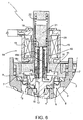
Figure 5 is a sectional view of another variant embodiment, and -
Figures 6 and7 are sectional views of further variant embodiments. - In
Figure 1 , thenumber 1 indicates the whole of a solenoid valve according to the invention, which can be used for example to control the supply of water from the water mains to a machine for washing such as a washing machine or a dishwasher. - The
solenoid valve 1 comprises abody 2, made from moulded plastic material for example, in which aninlet passage 3 for a fluid (typically a hydraulic fluid) and anoutlet passage 4 for this fluid are formed. In the illustrated exemplary embodiment, thesepassages - The
outlet passage 4 is made in atubular formation 5 of thebody 2, the upper part of this formation defining amain valve seat 6. A flow of fluid can pass through thisvalve seat 6 from theinlet 3 to theoutlet 4. - A
second body 7, also made of plastic material for example, is coupled to the top of thebody 2 in a fluid-tight way. - A
peripheral portion 8a of an annular diaphragm indicated as a whole by 8 is clamped between thebodies membrane 8 comprises a flexibleintermediate portion 8b, which connects theperipheral portion 8a to a thickened centralannular portion 8c intended to act as the main plug interacting with thevalve seat 6. - The
portion 8c is mounted around ashank 9a of an essentially cup-shaped guide element 9, and is secured on this shank by means of anannular element 10. - The
shaped body 7 has an uppertubular formation 7a, closed at its upper end. - A control chamber, indicated by 11, is formed between the
body 7 and the assembly formed by thediaphragm 8 and theassociated guide element 9. - The
control chamber 11 is in permanent fluid communication with theinlet 3, through at least one passage which, in the illustrated exemplary embodiment, is formed in the unit comprising thediaphragm 8 and theassociated guide element 9. In particular, as shown inFigure 1 , a plurality of throughholes 8d are formed in theportion 8c of themembrane 8, outside thevalve seat 6. These holes communicate with anannular compartment 9b formed in thediaphragm guide element 9, this compartment communicating in turn with correspondingouter grooves 9c which are also formed in thediaphragm guide 9. - As an alternative to the illustrated arrangement, communication between the
inlet 3 and thechamber 11 can be established by means of passages provided in thediaphragm 8 and in the associateddiaphragm guide 9, or provided in the body of the solenoid valve device. - The
number 12 indicates a passage formed in thediaphragm guide 9, which can put thecontrol chamber 11 into communication with theoutlet passage 4. - In the illustrated embodiment, a
tube 13, made of steel for example, is fitted in the upper portion of thepassage 12, this tube having a projectingupper rim 13a which can act as a valve seat, as explained more fully below. - The solenoid valve device additionally comprises a control solenoid valve indicated as a whole by 14. This control solenoid valve comprises an
operating solenoid 15 which is associated, in a known way, with a magnetic circuit comprising two tubular elements, namely anupper element 16a and alower element 16b, which extend axially from opposite ends into this solenoid. - The corresponding ends of the
elements solenoid 15. - The assembly formed by the
solenoid 15 and the associatedmagnetic elements tubular portion 7a of thebody 7. - The
control solenoid valve 14 also comprises a unit indicated as a whole by 17, which is mounted movably in thesolenoid 15, and, in particular, is mounted movably with a radial clearance within thetubular portion 7a of thebody 7. Thisunit 17 comprises amovable core 18 of ferromagnetic material, which bears on thevalve seat 13a in the rest state (when thesolenoid valve device 1 is closed). - The movable
ferromagnetic core 18 is mounted inside aspacer element 19 made from non-magnetic material. In the illustrated exemplary embodiment, the spacer element is tubular (although it could be made in other shapes) and extends with a radial clearance inside thetubular portion 7a of thebody 7. - The lower end of the
element 19 has a larger diameter, and bears on thediaphragm guide 9 around thevalve seat 13a. - The
movable core 18 has aradial shoulder 18a, and acoil spring 20 is positioned between this shoulder and a facinginner shoulder 19a of the aforesaidtubular element 19. Thespring 20 tends to push themovable core 18 against theseat 13a so that the core acts as a plug. - A second ferromagnetic core, indicated by 21, is positioned above the
tubular element 19, in theportion 7a of thebody 7. - A
coil spring 22 is positioned between the upper end of thesecond core 21 and the upper end wall of theportion 7a of thebody 7. Thisspring 22 tends to push thecore 21 and thetubular element 19 downwards, particularly in such a way that the lower end of thetubular element 19 is kept in contact with thediaphragm guide 9. - A
spring 20 can be positioned in thegap 24 between thecores spring 22 described above, in which case theelement 19 and thecore 18 do not have to be provided with the corresponding shoulders (as is seen in the variant shown inFigure 2 ). - In the upper part of the
tubular element 19, adjacent to thecore 21, there is formed at least one aperture, indicated by 23 inFigure 1 , through which the gap formed between theportion 7a of thebody 7 and theelement 19 communicates with the gap formed between thiselement 19 and the lateral wall of thecore 18. - The
spacer element 19 can be separate and distinct from thecore 21 and from thediaphragm guide 9, or can be integral with (or otherwise permanently fixed to) one and/or the other of the latter members (Figure 2 shows an embodiment which is similar to that ofFigure 1 , but which differs from it essentially in that theelement 19 is made in one piece with the diaphragm guide 9). - In the rest state of the
solenoid valve 1, shown inFigure 1 , thecores - In operation, when the
solenoid 15 is inactive, the fluid supplied to theinlet 3 enters thecontrol chamber 11 through the passage orpassages plug 18 closes thevalve seat 13a, and thecontrol chamber 11 is brought to the same fluid pressure as theinlet passage 3. - The
portion 8c of thediaphragm 8, which acts as the main plug, bears on thevalve seat 6, because the surface area of this diaphragm and of the associateddiaphragm guide 9 exposed to the pressure in thechamber 11 is greater than the surface area of themembrane 8 which is exposed to the pressure in thepassage 3. Themain valve 8c-6 is therefore closed. - When the
solenoid 15 is energized, a magnetic flux passes from themagnetic element 16a to thecore 21, across thegap 24 to thecore 18, and from there to the lowermagnetic element 16b. Thus thecore 18 is attracted towards thecore 21. This attraction causes thevalve seat 13a to be opened against the action of thespring 20. - The fluid pressure in the
control chamber 11 can then be discharged towards theoutlet passage 4, through thetube 13 and thepassage 12 of thediaphragm guide 9. - As the pressure in the
control chamber 11 decreases, the pressure in theinlet passage 3 which is applied to thediaphragm 8 causes the assembly formed by the diaphragm and the associateddiaphragm guide 9 to rise, thus opening themain valve 8c-6. - The fluid supplied to the
inlet passage 3 of thesolenoid valve 1 can then reach the outlet passage through thevalve seat 6. - The raising of the
plug core 21 to be raised by a corresponding amount and to draw with it thecore 18 which is magnetically attracted to it; theseat 13a therefore continues to remain open. - The electrical power required to energize the
solenoid 15 so as to create and maintain the attraction of thecore 18 towards thecore 21 is extremely low, and in particular it is independent of the opening travel of themain plug - As a general rule, with reference to
Figures 1 and2 , the distance (the height of the gap 24) between thecores magnetic elements cores magnetic elements magnetic elements - As shown in
Figure 1 , thegap 24, across which thecores magnetic elements - In other similar variant embodiments (see
Figure 3 for example), theelements 16a antmovable core 21 preferably extends upwards to a point in the proximity of the upper end of thesolenoid 15. - With reference to
Figure 1 , when thesolenoid 15 is energized,fluid 3 flows from the inlet, through thepassages control chamber 11, and then flows towards the upper part of the inner region of thetubular portion 7a of thebody 7, through the gap formed between thistubular portion 7a and thetubular element 19. This fluid can then flow back downwards through theaperture 23 and the gap formed between thetubular element 19 and thecore 18, towards the passage 12-13 and theoutlet passage 4. The flow of fluid established in this way in thesolenoid 15 advantageously reduces the temperature of the solenoid. - When the
solenoid 15 is de-energized, thesprings cores Figure 1 . The core 18 again shuts off thevalve seat 13a, thus separating thecontrol chamber 11 from theoutlet passage 4. - The unit formed by the
diaphragm 8 and the associateddiaphragm guide 9 can then return to the closed position of themain valve seat 6. -
Figures 3 and4 show another variant embodiment. In these figures, parts and elements identical or functionally equivalent to parts and elements described previously have been given the same alphanumeric references as those used before. - In the embodiment shown in
Figures 3 and4 , the upper end of thepassage 12 forms a projectingedge 13 which can act as a valve seat, as explained more fully below. - The
solenoid valve device 1 illustrated therein also comprises acontrol solenoid valve 14, comprising an operatingsolenoid 15 associated with a magnetic circuit comprising an essentially C-shaped shell 16 (Figure 3 ). - The assembly formed by the
solenoid 15 and the associatedmagnetic shell 16 is mounted around thetubular portion 7a of thebody 7. - The
control solenoid valve 14 also comprises a unit indicated as a whole by 17, which is mounted movably in thesolenoid 15, and, in particular, is mounted movably with a radial clearance within the lowertubular portion 7a of thebody 7. Thisunit 17 comprises amovable core 18 of ferromagnetic material, carrying at its lower end aplug 118a which bears on thevalve seat 13 in the rest state (when thesolenoid valve device 1 is closed). - The movable
ferromagnetic core 18 has alongitudinal passage 18b within which aspacer element 19 of non-magnetic material extends. In the exemplary embodiment shown inFigures 3 and4 , the spacer element is in the form of a rod (although it could be made in other shapes), and extends towards the top of theelement 9 of themain plug 8, with a radial clearance through (and beyond) thepassage 18b of thecore 18. - A second ferromagnetic core, indicated by 21, is positioned above the
spacer element 19, in theportion 7a of thebody 7. - A
coil spring 20 is positioned between the core 18 and a facing shoulder of thecore 21. Thespring 20 tends to push themovable core 18 and the associatedplug 18a against theseat 13. - A
coil spring 22 is positioned between the upper end of thesecond core 21 and the upper end wall of theportion 7a of thebody 7. Thisspring 22 tends to push thecore 21 downwards, particularly in such a way as to hold the latter against the upper end of thespacer element 19. - The
spacer element 19 can be integral with (or otherwise permanently connected to) the diaphragm guide 9 (as shown inFigures 3 and4 ) and/or thesecond core 21. - The length of the
spacer element 19 is such that, in the rest state of thesolenoid valve 1, shown in the figures, thecores - In operation, when the
solenoid 15 is inactive, the fluid supplied to theinlet 3 enters thecontrol chamber 11 through the passage orpassages valve seat 13, and thecontrol chamber 11 is brought to the same fluid pressure as theinlet passage 3. - The
portion 8c of thediaphragm 8, which acts as the main plug, bears on thevalve seat 6, because the surface area of this diaphragm and of the associateddiaphragm guide 9 exposed to the pressure in thechamber 11 is greater than the surface area of themembrane 8 which is exposed to the pressure in thepassage 3. Themain valve 8c-6 is therefore closed. - When the
solenoid 15 is energized, a magnetic flux passes into thecore 21 and through thegap 24 into thecore 18, and then from here to themagnetic element 16. Thus thecore 18 is attracted towards thecore 21. This attraction causes thevalve seat 13 to be opened against the action of thespring 20. - The fluid pressure in the
control chamber 11 can then be discharged towards theoutlet passage 4, through thepassage 12 of thediaphragm guide 9. - As the pressure in the
control chamber 11 decreases, the pressure in theinlet passage 3 which is applied to thediaphragm 8 causes the assembly formed by the diaphragm and the associateddiaphragm guide 9 to rise, thus opening themain valve 8c-6. - The fluid supplied to the
inlet passage 3 of thesolenoid valve 1 can then reach the outlet passage through thevalve seat 6. - The raising of the
plug seat 13 therefore continues to remain open. - The electrical power required to energize the
solenoid 15 so as to create and maintain the attraction of the core 18 towards thecore 21 is extremely low, and in particular it is independent of the opening travel of themain plug -
Figure 5 shows another variant embodiment. In this figure, parts and elements described previously have again been given the same alphanumeric references as those used previously. - In the variant shown in
Figure 5 , thespacer rod 19 is integral with the upperferromagnetic core 21, being for example mounted with an interference fit in arecess 21 a of this core. -
Figure 6 shows a variant embodiment of the lowermovable core 18, which comprises aferromagnetic part 18d and apart 18c made from non-magnetic material. - Clearly, the two variants shown in
Figures 5 and6 can be combined with each other. -
Figure 7 shows another variant embodiment. In this drawing also, parts and elements described previously have been given the same alphanumeric references as those used previously. - In the variant of
Figure 7 , a spacing structure, including atubular element 19 and a plurality ofrods 19b spaced apart angularly within thepassage 13 of thediaphragm guide 9, is positioned between thediaphragm guide 9 and the secondmovable core 21. Thetubular element 19 extends between ashoulder 21a of thecore 21 and therods 19b, around thespring 20 and themovable core 18. - Between the
rods 19b there are formedlarge apertures 19c which, in operation, allow the water which flows from thechamber 11 towards theoutlet 4 to flush thepassage 13 and its surrounding region thoroughly, thus removing any sediment which might lead to the clogging of this passage over time. - The
rods 19b can be integral with and/or fixed to thediaphragm guide 9, and thetubular element 19 can be fixed to or fitted on thecore 21 and can bear on saidrods 19b. Alternatively, therods 19b can be integral with thetubular element 19 and can bear on thediaphragm guide 9. - Clearly, provided that the principle of the invention is retained, the forms of application and the details of construction can be varied widely from what has been described and illustrated purely by way of non-limiting example, without thereby departing from the scope of protection of the invention as defined by the attached claims.
Claims (6)
- Solenoid valve device (1) comprising:- a body (2, 7) with an inlet (3) and an outlet (4) for the fluid, and with a main valve seat (6) through which the fluid can flow from the inlet (3) to the outlet (4),- a main plug (8, 9) which is movable with respect to said valve seat (6) between a closed position and an open position of said valve seat (6);- a control chamber (11) formed in the body (2, 7) and partially delimited by the main plug (8);- at least a first passage (8d, 9b, 9c) for communication between the inlet (3) and the control chamber (11);- at least a second passage (12, 13) for putting the control chamber (11) into communication with the outlet (4); and- a control solenoid valve (14) including a control solenoid (15) which controls a unit (17) which is movable in said solenoid (15) and which comprises a first ferromagnetic core (18) which can interact as a movable plug with said second passage (12, 13);wherein said movable unit (17) comprises an additional or second movable ferromagnetic core (21) positioned in said solenoid (15) adjacent to one end of the aforesaid first core (18), and positioning means (19, 20, 22) are provided for keeping the second movable core (21) permanently connected to the main plug (8, 9) and, when the solenoid (15) is inactive, for keeping the first core (18) in the closed position of said second passage (12, 13) and the second core (21) in a predetermined position with respect to the first core (18) and to the solenoid (15), said cores (18, 21) being separated by a gap (24); said positioning means comprising a substantially non-magnetic spacer element (19) which extends between the main plug (8, 9) and said second movable core (21);
the arrangement being such that the energizing of the solenoid (15) causes the first core (18) to be attracted towards the second core (21) and causes said second passage (12, 13) to be opened, and a flow of fluid from the inlet (3) passes through the first passage (8d, 9b, 9c) to the control chamber (11);
the solenoid valve device being characterised in that said spacer element (19) extends with a radial clearance within the solenoid (15) and around the first core (18) and has at least one aperture (23) in the proximity of the second core (21);
the arrangement being such that, when the solenoid (15) is activated, a flow of fluid flows between the solenoid (15) and said spacer element (19) towards the second core (21), and then flows through said at least one aperture (23) of the spacer element (19) between the spacer element (19) and the first core (18) towards said second passage (13, 12). - Solenoid valve device according to Claim 1, in which the spacer element (19) is permanently connected to the main plug (8, 9) and/or to the second movable core (21), and the positioning means comprise first resilient means (22) tending to push said second movable core (21) towards the main core (18).
- Solenoid valve device according to any one of the preceding claims, in which said positioning means comprise first and second resilient means (20, 22) tending to return the first and second movable cores (18, 21), respectively, towards the main plug (8, 9).
- Solenoid valve device according to Claim 3, in which said first resilient means comprise a spring (25) positioned in the aforesaid gap (24).
- Solenoid valve device according to Claim 3, in which said first resilient means (20) extend between a reaction surface (18a) of the first core (18) and a reaction surface (19a) of said spacer element (19).
- Solenoid valve device according to any one of the preceding claims, in which the solenoid (15) is associated with a magnetic circuit comprising a first and a second magnetic core (16a, 16b) which extend axially from opposite ends within the solenoid (15) and have corresponding ends which face each other at a predetermined distance, in an axially intermediate portion of the solenoid (15), and in which, in the inactive state of the solenoid (15), the first and the second core (18, 21) face each other in an area located between the facing ends of said magnetic elements (16a, 16b) with respect to the axis, the distance between the cores (18, 21) and the distance between the cores (18, 21) and said magnetic elements (16a, 16b) being less than the distance between the facing ends of said magnetic elements (16a, 16b).
Priority Applications (2)
| Application Number | Priority Date | Filing Date | Title |
|---|---|---|---|
| PL10805523T PL2501970T3 (en) | 2009-11-21 | 2010-11-22 | Electromagnetic valve device |
| SI201030461T SI2501970T1 (en) | 2009-11-21 | 2010-11-22 | Electromagnetic valve device |
Applications Claiming Priority (3)
| Application Number | Priority Date | Filing Date | Title |
|---|---|---|---|
| ITTO2009A000897A IT1397022B1 (en) | 2009-11-21 | 2009-11-21 | ELECTROVALVULAR DEVICE |
| ITTO2010A000844A IT1402227B1 (en) | 2010-10-19 | 2010-10-19 | ELECTROVALVULAR DEVICE |
| PCT/IT2010/000466 WO2011061777A1 (en) | 2009-11-20 | 2010-11-22 | Electromagnetic valve device |
Publications (2)
| Publication Number | Publication Date |
|---|---|
| EP2501970A1 EP2501970A1 (en) | 2012-09-26 |
| EP2501970B1 true EP2501970B1 (en) | 2013-09-25 |
Family
ID=43795177
Family Applications (1)
| Application Number | Title | Priority Date | Filing Date |
|---|---|---|---|
| EP10805523.7A Not-in-force EP2501970B1 (en) | 2009-11-21 | 2010-11-22 | Electromagnetic valve device |
Country Status (14)
| Country | Link |
|---|---|
| US (1) | US8960638B2 (en) |
| EP (1) | EP2501970B1 (en) |
| JP (1) | JP5661790B2 (en) |
| KR (1) | KR101832999B1 (en) |
| CN (1) | CN102667283B (en) |
| AU (1) | AU2010320447B2 (en) |
| BR (1) | BR112012011911A2 (en) |
| CA (1) | CA2781017C (en) |
| ES (1) | ES2439066T3 (en) |
| MX (1) | MX2012005793A (en) |
| NZ (1) | NZ600019A (en) |
| PL (1) | PL2501970T3 (en) |
| SI (1) | SI2501970T1 (en) |
| WO (1) | WO2011061777A1 (en) |
Families Citing this family (24)
| Publication number | Priority date | Publication date | Assignee | Title |
|---|---|---|---|---|
| ES2370898B1 (en) * | 2011-11-03 | 2012-11-06 | Bitron Industrie España, S.A. | CLOSURE SYSTEM, ESPECIALLY FOR AN ELECTROVALVULA AND ELECTROVALVULA PROVIDED WITH SUCH CLOSURE SYSTEM. |
| DE102013225530A1 (en) * | 2013-12-11 | 2015-06-25 | BSH Hausgeräte GmbH | Household appliance with a solenoid valve |
| DE102013225537B4 (en) * | 2013-12-11 | 2016-04-21 | BSH Hausgeräte GmbH | Household appliance with a solenoid valve |
| KR101628569B1 (en) * | 2014-12-11 | 2016-06-08 | 현대자동차주식회사 | High pressure solenoid valve |
| US10352470B2 (en) * | 2015-11-17 | 2019-07-16 | Ge Aviation Systems Llc | Control valve and air starting system |
| WO2017137395A1 (en) * | 2016-02-11 | 2017-08-17 | Danfoss A/S | Valve arrangement and diaphragm assembly for a valve arrangement |
| JP2017201198A (en) * | 2016-05-06 | 2017-11-09 | Toto株式会社 | Flow adjustment valve |
| US10480676B2 (en) * | 2016-08-01 | 2019-11-19 | Smc Corporation | Valve |
| US10993546B2 (en) | 2016-10-28 | 2021-05-04 | Sleep Number Corporation | Noise reducing plunger |
| DE102016014432A1 (en) * | 2016-12-05 | 2018-06-07 | Thomas Magnete Gmbh | Switching actuated valve |
| KR102274114B1 (en) * | 2017-01-25 | 2021-07-06 | 현대자동차주식회사 | Solenoid valve including pilot plunger head which is moving independently from the pilot plunger |
| US10675433B2 (en) * | 2017-05-25 | 2020-06-09 | MGC Diagnostics Corporation | Solenoid controlled respiratory gas demand valve |
| EP3480500B1 (en) * | 2017-10-03 | 2021-09-15 | Rotex Automation Limited | Solenoid valve with integral pressure relief arrangement |
| WO2019155500A1 (en) * | 2018-02-12 | 2019-08-15 | Ceme S.P.A. | Magnetically-operable shutter assembly |
| IT201800005892A1 (en) * | 2018-05-31 | 2019-12-01 | Valve for fluids, preferably for gas | |
| IT201800005897A1 (en) * | 2018-05-31 | 2019-12-01 | Valve for fluids, preferably for gas | |
| US11300223B2 (en) * | 2018-12-07 | 2022-04-12 | Robertshaw Controls Company | Self-cleaning water passageways on diaphragm insert |
| CN109654249B (en) * | 2018-12-20 | 2020-06-09 | 珠海优特智厨科技有限公司 | Pinch valve |
| CN112539292B (en) * | 2019-09-23 | 2022-02-11 | 江门市甜的电器有限公司 | Water inlet electromagnetic valve capable of improving electromagnetic suction force and implementation method |
| EP4112984A1 (en) * | 2021-06-30 | 2023-01-04 | Danfoss A/S | Pilot controlled solenoid valve |
| US11832728B2 (en) | 2021-08-24 | 2023-12-05 | Sleep Number Corporation | Controlling vibration transmission within inflation assemblies |
| JP7796232B2 (en) * | 2022-07-20 | 2026-01-08 | 浙江盾安人工環境股▲ふん▼有限公司 | drainage structure |
| CN116006694A (en) * | 2023-01-05 | 2023-04-25 | 余姚市永创电磁阀有限公司 | A piston-type ultra-high pressure solenoid valve that can be used for hydrogen |
| CN116336245B (en) * | 2023-04-21 | 2026-01-02 | 箭牌家居集团股份有限公司 | Solenoid valves and water outlet devices |
Family Cites Families (22)
| Publication number | Priority date | Publication date | Assignee | Title |
|---|---|---|---|---|
| JPS49106015A (en) * | 1973-02-13 | 1974-10-08 | ||
| JPS5162127U (en) * | 1974-11-12 | 1976-05-17 | ||
| JPS60147725U (en) * | 1984-03-09 | 1985-10-01 | トヨタ自動車株式会社 | Solenoid valve for fuel injection pump |
| JPS62124379U (en) * | 1986-01-31 | 1987-08-07 | ||
| JPS6360779U (en) * | 1986-10-09 | 1988-04-22 | ||
| JPS6431274U (en) * | 1987-08-20 | 1989-02-27 | ||
| JPH05306786A (en) * | 1992-05-06 | 1993-11-19 | Mitsubishi Heavy Ind Ltd | Solenoid valve |
| JP3367122B2 (en) | 1992-11-30 | 2003-01-14 | 東陶機器株式会社 | solenoid |
| US5622351A (en) * | 1994-05-31 | 1997-04-22 | Daewoo Electronics Co., Ltd. | Water-supply valve of a washing machine |
| JPH07332534A (en) * | 1994-06-03 | 1995-12-22 | Toto Ltd | Pilot operating automatic closing fluid controlling solenoid valve |
| GB2296075B (en) | 1994-12-12 | 1998-08-05 | Elbi Int Spa | A support and guide unit for an obturator of a solenoid valve and a method for the manufacture thereof |
| KR100420662B1 (en) * | 1995-09-08 | 2004-06-05 | 도토기키 가부시키가이샤 | Solenoid and Solenoid Valves |
| JP2000130628A (en) * | 1998-10-30 | 2000-05-12 | Smc Corp | Solenoid valve |
| JP4054932B2 (en) * | 1999-03-25 | 2008-03-05 | 株式会社デンソー | Solenoid valve for fluid pressure control |
| US6290203B1 (en) * | 2000-01-18 | 2001-09-18 | Kolze, Inc. | Pilot operated valve assembly |
| JP3944882B2 (en) * | 2003-03-11 | 2007-07-18 | 京セラミタ株式会社 | Facsimile device with memory transfer function |
| DE102004004708B3 (en) * | 2004-01-30 | 2005-04-21 | Karl Dungs Gmbh & Co. Kg | Magnetically-operated double-seat valve for shutting off fluid flow has armature moving circular seal engaging triangular-section seat and surrounding inner valve with triangular-section seal |
| US7428913B2 (en) * | 2005-04-26 | 2008-09-30 | Mks Instruments, Inc. | Valve assembly having articulating rigid seating surface |
| DE102007043554A1 (en) * | 2007-03-10 | 2008-09-11 | Continental Teves Ag & Co. Ohg | valve assembly |
| CN101311590B (en) * | 2007-05-24 | 2011-03-30 | 浙江三花制冷集团有限公司 | Solenoid valve for controlling flow path |
| WO2009049625A1 (en) | 2007-10-18 | 2009-04-23 | Danfoss A/S | A magnetic actuator and a valve comprising such an actuator |
| CN201344313Y (en) * | 2008-12-19 | 2009-11-11 | 川北科技(北京)有限公司 | Vacuum electromagnetic baffle inflation valve |
-
2010
- 2010-11-22 AU AU2010320447A patent/AU2010320447B2/en not_active Ceased
- 2010-11-22 WO PCT/IT2010/000466 patent/WO2011061777A1/en not_active Ceased
- 2010-11-22 CN CN201080052480.6A patent/CN102667283B/en not_active Expired - Fee Related
- 2010-11-22 MX MX2012005793A patent/MX2012005793A/en active IP Right Grant
- 2010-11-22 US US13/510,852 patent/US8960638B2/en not_active Expired - Fee Related
- 2010-11-22 PL PL10805523T patent/PL2501970T3/en unknown
- 2010-11-22 BR BR112012011911A patent/BR112012011911A2/en active Search and Examination
- 2010-11-22 NZ NZ600019A patent/NZ600019A/en not_active IP Right Cessation
- 2010-11-22 EP EP10805523.7A patent/EP2501970B1/en not_active Not-in-force
- 2010-11-22 JP JP2012539474A patent/JP5661790B2/en not_active Expired - Fee Related
- 2010-11-22 SI SI201030461T patent/SI2501970T1/en unknown
- 2010-11-22 ES ES10805523.7T patent/ES2439066T3/en active Active
- 2010-11-22 KR KR1020127015866A patent/KR101832999B1/en not_active Expired - Fee Related
- 2010-11-22 CA CA2781017A patent/CA2781017C/en not_active Expired - Fee Related
Also Published As
| Publication number | Publication date |
|---|---|
| CN102667283A (en) | 2012-09-12 |
| CN102667283B (en) | 2014-12-24 |
| EP2501970A1 (en) | 2012-09-26 |
| US8960638B2 (en) | 2015-02-24 |
| JP2013511679A (en) | 2013-04-04 |
| MX2012005793A (en) | 2012-09-28 |
| ES2439066T3 (en) | 2014-01-21 |
| BR112012011911A2 (en) | 2016-03-15 |
| PL2501970T3 (en) | 2014-02-28 |
| AU2010320447B2 (en) | 2015-08-06 |
| WO2011061777A1 (en) | 2011-05-26 |
| CA2781017C (en) | 2017-07-11 |
| US20120228535A1 (en) | 2012-09-13 |
| NZ600019A (en) | 2013-09-27 |
| KR20120088852A (en) | 2012-08-08 |
| JP5661790B2 (en) | 2015-01-28 |
| SI2501970T1 (en) | 2014-01-31 |
| AU2010320447A1 (en) | 2012-06-14 |
| KR101832999B1 (en) | 2018-04-13 |
| CA2781017A1 (en) | 2011-05-26 |
Similar Documents
| Publication | Publication Date | Title |
|---|---|---|
| CA2781017C (en) | Electromagnetic valve device | |
| EP2775110B1 (en) | Oil pump control valve | |
| EP3120060B1 (en) | Bistable electric valve, in particular for a system for recovering petrol vapours in a motor vehicle | |
| EP3259466B1 (en) | Bistable electric valve, particularly for a system for recovery of petrol vapours in a motor-vehicle | |
| EP2751461B1 (en) | Solenoid pilot valve for a hydraulic valve, in particular for household appliances | |
| EP2539615B1 (en) | An electric valve device | |
| CN102177057A (en) | Solenoid valve | |
| KR20080114738A (en) | Solenoid valve | |
| JP6587100B2 (en) | Solenoid valve | |
| KR101536190B1 (en) | Solenoid valve for brake system | |
| EP1740864B1 (en) | A solenoid-operated safety valve device particularly for a washing machine | |
| KR20090037015A (en) | Solenoid Valve for Brake System | |
| WO2006134479A2 (en) | Solenoid valve | |
| KR101279423B1 (en) | Solenoid valve for brake system | |
| KR20130115669A (en) | Solenoid valve for brake system | |
| US20160265682A1 (en) | Valve, in particular water discharge valve for toilets | |
| JP5867833B2 (en) | Pilot operated electromagnetic water supply valve | |
| ITTO20090897A1 (en) | ELECTROVALVULAR DEVICE | |
| KR20140104302A (en) | Normal open type solenoid valve in vehicle's | |
| ITTO20100844A1 (en) | ELECTROVALVULAR DEVICE | |
| WO2006008671A1 (en) | A proportional hydraulic solenoid valve |
Legal Events
| Date | Code | Title | Description |
|---|---|---|---|
| PUAI | Public reference made under article 153(3) epc to a published international application that has entered the european phase |
Free format text: ORIGINAL CODE: 0009012 |
|
| 17P | Request for examination filed |
Effective date: 20120514 |
|
| AK | Designated contracting states |
Kind code of ref document: A1 Designated state(s): AL AT BE BG CH CY CZ DE DK EE ES FI FR GB GR HR HU IE IS IT LI LT LU LV MC MK MT NL NO PL PT RO RS SE SI SK SM TR |
|
| DAX | Request for extension of the european patent (deleted) | ||
| GRAP | Despatch of communication of intention to grant a patent |
Free format text: ORIGINAL CODE: EPIDOSNIGR1 |
|
| INTG | Intention to grant announced |
Effective date: 20130503 |
|
| GRAS | Grant fee paid |
Free format text: ORIGINAL CODE: EPIDOSNIGR3 |
|
| GRAA | (expected) grant |
Free format text: ORIGINAL CODE: 0009210 |
|
| AK | Designated contracting states |
Kind code of ref document: B1 Designated state(s): AL AT BE BG CH CY CZ DE DK EE ES FI FR GB GR HR HU IE IS IT LI LT LU LV MC MK MT NL NO PL PT RO RS SE SI SK SM TR |
|
| REG | Reference to a national code |
Ref country code: GB Ref legal event code: FG4D |
|
| REG | Reference to a national code |
Ref country code: CH Ref legal event code: EP |
|
| REG | Reference to a national code |
Ref country code: AT Ref legal event code: REF Ref document number: 633849 Country of ref document: AT Kind code of ref document: T Effective date: 20131015 |
|
| REG | Reference to a national code |
Ref country code: IE Ref legal event code: FG4D |
|
| REG | Reference to a national code |
Ref country code: DE Ref legal event code: R096 Ref document number: 602010010602 Country of ref document: DE Effective date: 20131121 |
|
| REG | Reference to a national code |
Ref country code: SE Ref legal event code: TRGR |
|
| REG | Reference to a national code |
Ref country code: ES Ref legal event code: FG2A Ref document number: 2439066 Country of ref document: ES Kind code of ref document: T3 Effective date: 20140121 |
|
| PG25 | Lapsed in a contracting state [announced via postgrant information from national office to epo] |
Ref country code: LT Free format text: LAPSE BECAUSE OF FAILURE TO SUBMIT A TRANSLATION OF THE DESCRIPTION OR TO PAY THE FEE WITHIN THE PRESCRIBED TIME-LIMIT Effective date: 20130925 Ref country code: HR Free format text: LAPSE BECAUSE OF FAILURE TO SUBMIT A TRANSLATION OF THE DESCRIPTION OR TO PAY THE FEE WITHIN THE PRESCRIBED TIME-LIMIT Effective date: 20130925 Ref country code: NO Free format text: LAPSE BECAUSE OF FAILURE TO SUBMIT A TRANSLATION OF THE DESCRIPTION OR TO PAY THE FEE WITHIN THE PRESCRIBED TIME-LIMIT Effective date: 20131225 |
|
| REG | Reference to a national code |
Ref country code: AT Ref legal event code: MK05 Ref document number: 633849 Country of ref document: AT Kind code of ref document: T Effective date: 20130925 |
|
| REG | Reference to a national code |
Ref country code: NL Ref legal event code: VDEP Effective date: 20130925 |
|
| REG | Reference to a national code |
Ref country code: LT Ref legal event code: MG4D |
|
| PG25 | Lapsed in a contracting state [announced via postgrant information from national office to epo] |
Ref country code: RS Free format text: LAPSE BECAUSE OF FAILURE TO SUBMIT A TRANSLATION OF THE DESCRIPTION OR TO PAY THE FEE WITHIN THE PRESCRIBED TIME-LIMIT Effective date: 20130925 Ref country code: FI Free format text: LAPSE BECAUSE OF FAILURE TO SUBMIT A TRANSLATION OF THE DESCRIPTION OR TO PAY THE FEE WITHIN THE PRESCRIBED TIME-LIMIT Effective date: 20130925 Ref country code: GR Free format text: LAPSE BECAUSE OF FAILURE TO SUBMIT A TRANSLATION OF THE DESCRIPTION OR TO PAY THE FEE WITHIN THE PRESCRIBED TIME-LIMIT Effective date: 20131226 Ref country code: LV Free format text: LAPSE BECAUSE OF FAILURE TO SUBMIT A TRANSLATION OF THE DESCRIPTION OR TO PAY THE FEE WITHIN THE PRESCRIBED TIME-LIMIT Effective date: 20130925 |
|
| REG | Reference to a national code |
Ref country code: PL Ref legal event code: T3 |
|
| PG25 | Lapsed in a contracting state [announced via postgrant information from national office to epo] |
Ref country code: BE Free format text: LAPSE BECAUSE OF FAILURE TO SUBMIT A TRANSLATION OF THE DESCRIPTION OR TO PAY THE FEE WITHIN THE PRESCRIBED TIME-LIMIT Effective date: 20130925 |
|
| PG25 | Lapsed in a contracting state [announced via postgrant information from national office to epo] |
Ref country code: CZ Free format text: LAPSE BECAUSE OF FAILURE TO SUBMIT A TRANSLATION OF THE DESCRIPTION OR TO PAY THE FEE WITHIN THE PRESCRIBED TIME-LIMIT Effective date: 20130925 Ref country code: EE Free format text: LAPSE BECAUSE OF FAILURE TO SUBMIT A TRANSLATION OF THE DESCRIPTION OR TO PAY THE FEE WITHIN THE PRESCRIBED TIME-LIMIT Effective date: 20130925 Ref country code: IS Free format text: LAPSE BECAUSE OF FAILURE TO SUBMIT A TRANSLATION OF THE DESCRIPTION OR TO PAY THE FEE WITHIN THE PRESCRIBED TIME-LIMIT Effective date: 20140125 Ref country code: SK Free format text: LAPSE BECAUSE OF FAILURE TO SUBMIT A TRANSLATION OF THE DESCRIPTION OR TO PAY THE FEE WITHIN THE PRESCRIBED TIME-LIMIT Effective date: 20130925 Ref country code: RO Free format text: LAPSE BECAUSE OF FAILURE TO SUBMIT A TRANSLATION OF THE DESCRIPTION OR TO PAY THE FEE WITHIN THE PRESCRIBED TIME-LIMIT Effective date: 20130925 Ref country code: NL Free format text: LAPSE BECAUSE OF FAILURE TO SUBMIT A TRANSLATION OF THE DESCRIPTION OR TO PAY THE FEE WITHIN THE PRESCRIBED TIME-LIMIT Effective date: 20130925 |
|
| PG25 | Lapsed in a contracting state [announced via postgrant information from national office to epo] |
Ref country code: CY Free format text: LAPSE BECAUSE OF FAILURE TO SUBMIT A TRANSLATION OF THE DESCRIPTION OR TO PAY THE FEE WITHIN THE PRESCRIBED TIME-LIMIT Effective date: 20130925 Ref country code: AT Free format text: LAPSE BECAUSE OF FAILURE TO SUBMIT A TRANSLATION OF THE DESCRIPTION OR TO PAY THE FEE WITHIN THE PRESCRIBED TIME-LIMIT Effective date: 20130925 |
|
| REG | Reference to a national code |
Ref country code: DE Ref legal event code: R097 Ref document number: 602010010602 Country of ref document: DE |
|
| PG25 | Lapsed in a contracting state [announced via postgrant information from national office to epo] |
Ref country code: PT Free format text: LAPSE BECAUSE OF FAILURE TO SUBMIT A TRANSLATION OF THE DESCRIPTION OR TO PAY THE FEE WITHIN THE PRESCRIBED TIME-LIMIT Effective date: 20140127 |
|
| PG25 | Lapsed in a contracting state [announced via postgrant information from national office to epo] |
Ref country code: MC Free format text: LAPSE BECAUSE OF FAILURE TO SUBMIT A TRANSLATION OF THE DESCRIPTION OR TO PAY THE FEE WITHIN THE PRESCRIBED TIME-LIMIT Effective date: 20130925 |
|
| PLBE | No opposition filed within time limit |
Free format text: ORIGINAL CODE: 0009261 |
|
| STAA | Information on the status of an ep patent application or granted ep patent |
Free format text: STATUS: NO OPPOSITION FILED WITHIN TIME LIMIT |
|
| REG | Reference to a national code |
Ref country code: IE Ref legal event code: MM4A |
|
| PG25 | Lapsed in a contracting state [announced via postgrant information from national office to epo] |
Ref country code: IT Free format text: LAPSE BECAUSE OF FAILURE TO SUBMIT A TRANSLATION OF THE DESCRIPTION OR TO PAY THE FEE WITHIN THE PRESCRIBED TIME-LIMIT Effective date: 20130925 |
|
| 26N | No opposition filed |
Effective date: 20140626 |
|
| PG25 | Lapsed in a contracting state [announced via postgrant information from national office to epo] |
Ref country code: DK Free format text: LAPSE BECAUSE OF FAILURE TO SUBMIT A TRANSLATION OF THE DESCRIPTION OR TO PAY THE FEE WITHIN THE PRESCRIBED TIME-LIMIT Effective date: 20130925 |
|
| REG | Reference to a national code |
Ref country code: DE Ref legal event code: R097 Ref document number: 602010010602 Country of ref document: DE Effective date: 20140626 |
|
| PG25 | Lapsed in a contracting state [announced via postgrant information from national office to epo] |
Ref country code: IE Free format text: LAPSE BECAUSE OF NON-PAYMENT OF DUE FEES Effective date: 20131122 |
|
| PG25 | Lapsed in a contracting state [announced via postgrant information from national office to epo] |
Ref country code: SM Free format text: LAPSE BECAUSE OF FAILURE TO SUBMIT A TRANSLATION OF THE DESCRIPTION OR TO PAY THE FEE WITHIN THE PRESCRIBED TIME-LIMIT Effective date: 20130925 |
|
| REG | Reference to a national code |
Ref country code: CH Ref legal event code: PL |
|
| PG25 | Lapsed in a contracting state [announced via postgrant information from national office to epo] |
Ref country code: MK Free format text: LAPSE BECAUSE OF FAILURE TO SUBMIT A TRANSLATION OF THE DESCRIPTION OR TO PAY THE FEE WITHIN THE PRESCRIBED TIME-LIMIT Effective date: 20130925 Ref country code: BG Free format text: LAPSE BECAUSE OF FAILURE TO SUBMIT A TRANSLATION OF THE DESCRIPTION OR TO PAY THE FEE WITHIN THE PRESCRIBED TIME-LIMIT Effective date: 20130925 Ref country code: LU Free format text: LAPSE BECAUSE OF NON-PAYMENT OF DUE FEES Effective date: 20131122 Ref country code: CH Free format text: LAPSE BECAUSE OF NON-PAYMENT OF DUE FEES Effective date: 20141130 Ref country code: HU Free format text: LAPSE BECAUSE OF FAILURE TO SUBMIT A TRANSLATION OF THE DESCRIPTION OR TO PAY THE FEE WITHIN THE PRESCRIBED TIME-LIMIT; INVALID AB INITIO Effective date: 20101122 Ref country code: LI Free format text: LAPSE BECAUSE OF NON-PAYMENT OF DUE FEES Effective date: 20141130 |
|
| PG25 | Lapsed in a contracting state [announced via postgrant information from national office to epo] |
Ref country code: MT Free format text: LAPSE BECAUSE OF FAILURE TO SUBMIT A TRANSLATION OF THE DESCRIPTION OR TO PAY THE FEE WITHIN THE PRESCRIBED TIME-LIMIT Effective date: 20130925 |
|
| REG | Reference to a national code |
Ref country code: FR Ref legal event code: PLFP Year of fee payment: 6 |
|
| REG | Reference to a national code |
Ref country code: FR Ref legal event code: PLFP Year of fee payment: 7 |
|
| REG | Reference to a national code |
Ref country code: FR Ref legal event code: PLFP Year of fee payment: 8 |
|
| PGFP | Annual fee paid to national office [announced via postgrant information from national office to epo] |
Ref country code: FR Payment date: 20171130 Year of fee payment: 8 |
|
| PGFP | Annual fee paid to national office [announced via postgrant information from national office to epo] |
Ref country code: SE Payment date: 20171116 Year of fee payment: 8 Ref country code: ES Payment date: 20171201 Year of fee payment: 8 Ref country code: GB Payment date: 20171123 Year of fee payment: 8 Ref country code: SI Payment date: 20171025 Year of fee payment: 8 |
|
| PG25 | Lapsed in a contracting state [announced via postgrant information from national office to epo] |
Ref country code: AL Free format text: LAPSE BECAUSE OF FAILURE TO SUBMIT A TRANSLATION OF THE DESCRIPTION OR TO PAY THE FEE WITHIN THE PRESCRIBED TIME-LIMIT Effective date: 20130925 |
|
| REG | Reference to a national code |
Ref country code: SE Ref legal event code: EUG |
|
| GBPC | Gb: european patent ceased through non-payment of renewal fee |
Effective date: 20181122 |
|
| PG25 | Lapsed in a contracting state [announced via postgrant information from national office to epo] |
Ref country code: SE Free format text: LAPSE BECAUSE OF NON-PAYMENT OF DUE FEES Effective date: 20181123 |
|
| PG25 | Lapsed in a contracting state [announced via postgrant information from national office to epo] |
Ref country code: SI Free format text: LAPSE BECAUSE OF NON-PAYMENT OF DUE FEES Effective date: 20181123 |
|
| REG | Reference to a national code |
Ref country code: SI Ref legal event code: KO00 Effective date: 20190708 |
|
| PG25 | Lapsed in a contracting state [announced via postgrant information from national office to epo] |
Ref country code: FR Free format text: LAPSE BECAUSE OF NON-PAYMENT OF DUE FEES Effective date: 20181130 |
|
| PG25 | Lapsed in a contracting state [announced via postgrant information from national office to epo] |
Ref country code: GB Free format text: LAPSE BECAUSE OF NON-PAYMENT OF DUE FEES Effective date: 20181122 |
|
| REG | Reference to a national code |
Ref country code: ES Ref legal event code: FD2A Effective date: 20200103 |
|
| PG25 | Lapsed in a contracting state [announced via postgrant information from national office to epo] |
Ref country code: ES Free format text: LAPSE BECAUSE OF NON-PAYMENT OF DUE FEES Effective date: 20181123 |
|
| PGFP | Annual fee paid to national office [announced via postgrant information from national office to epo] |
Ref country code: TR Payment date: 20191013 Year of fee payment: 10 |
|
| PGFP | Annual fee paid to national office [announced via postgrant information from national office to epo] |
Ref country code: PL Payment date: 20200923 Year of fee payment: 11 |
|
| PGFP | Annual fee paid to national office [announced via postgrant information from national office to epo] |
Ref country code: DE Payment date: 20211118 Year of fee payment: 12 |
|
| PG25 | Lapsed in a contracting state [announced via postgrant information from national office to epo] |
Ref country code: TR Free format text: LAPSE BECAUSE OF NON-PAYMENT OF DUE FEES Effective date: 20201122 |
|
| PG25 | Lapsed in a contracting state [announced via postgrant information from national office to epo] |
Ref country code: PL Free format text: LAPSE BECAUSE OF NON-PAYMENT OF DUE FEES Effective date: 20211122 |
|
| REG | Reference to a national code |
Ref country code: DE Ref legal event code: R119 Ref document number: 602010010602 Country of ref document: DE |
|
| PG25 | Lapsed in a contracting state [announced via postgrant information from national office to epo] |
Ref country code: DE Free format text: LAPSE BECAUSE OF NON-PAYMENT OF DUE FEES Effective date: 20230601 |