EP2501175A2 - Distributed capacity based channel assignment for communication systems - Google Patents
Distributed capacity based channel assignment for communication systems Download PDFInfo
- Publication number
- EP2501175A2 EP2501175A2 EP12157025A EP12157025A EP2501175A2 EP 2501175 A2 EP2501175 A2 EP 2501175A2 EP 12157025 A EP12157025 A EP 12157025A EP 12157025 A EP12157025 A EP 12157025A EP 2501175 A2 EP2501175 A2 EP 2501175A2
- Authority
- EP
- European Patent Office
- Prior art keywords
- channel
- capacity
- loss
- gain
- user equipment
- Prior art date
- Legal status (The legal status is an assumption and is not a legal conclusion. Google has not performed a legal analysis and makes no representation as to the accuracy of the status listed.)
- Granted
Links
Images


Classifications
-
- H—ELECTRICITY
- H04—ELECTRIC COMMUNICATION TECHNIQUE
- H04W—WIRELESS COMMUNICATION NETWORKS
- H04W28/00—Network traffic management; Network resource management
- H04W28/16—Central resource management; Negotiation of resources or communication parameters, e.g. negotiating bandwidth or QoS [Quality of Service]
-
- H—ELECTRICITY
- H04—ELECTRIC COMMUNICATION TECHNIQUE
- H04L—TRANSMISSION OF DIGITAL INFORMATION, e.g. TELEGRAPHIC COMMUNICATION
- H04L1/00—Arrangements for detecting or preventing errors in the information received
- H04L1/20—Arrangements for detecting or preventing errors in the information received using signal quality detector
-
- H—ELECTRICITY
- H04—ELECTRIC COMMUNICATION TECHNIQUE
- H04W—WIRELESS COMMUNICATION NETWORKS
- H04W16/00—Network planning, e.g. coverage or traffic planning tools; Network deployment, e.g. resource partitioning or cells structures
- H04W16/02—Resource partitioning among network components, e.g. reuse partitioning
- H04W16/10—Dynamic resource partitioning
-
- H—ELECTRICITY
- H04—ELECTRIC COMMUNICATION TECHNIQUE
- H04W—WIRELESS COMMUNICATION NETWORKS
- H04W72/00—Local resource management
- H04W72/04—Wireless resource allocation
- H04W72/044—Wireless resource allocation based on the type of the allocated resource
- H04W72/0453—Resources in frequency domain, e.g. a carrier in FDMA
-
- H—ELECTRICITY
- H04—ELECTRIC COMMUNICATION TECHNIQUE
- H04W—WIRELESS COMMUNICATION NETWORKS
- H04W28/00—Network traffic management; Network resource management
- H04W28/02—Traffic management, e.g. flow control or congestion control
- H04W28/04—Error control
-
- H—ELECTRICITY
- H04—ELECTRIC COMMUNICATION TECHNIQUE
- H04W—WIRELESS COMMUNICATION NETWORKS
- H04W72/00—Local resource management
- H04W72/50—Allocation or scheduling criteria for wireless resources
- H04W72/54—Allocation or scheduling criteria for wireless resources based on quality criteria
Definitions
- the present invention is directed, in general, to communication systems and, more particularly, to apparatuses and methods for providing additional capacity for local area communications over an air interface such as may be used with radio frequency communication systems.
- UMTS Universal Mobile Telecommunications System
- UTRAN UMTS Terrestrial Radio Access Network
- 3G third generation wireless
- 4G fourth generation wireless
- WCDMA Wideband Code Division Multiple Access
- the mobile equipment includes user equipment (“UE”) such as cell phones, and fixed transceivers that support mobile telephone cells, such as base stations, referred to as “Node B” (or “NB”) and when enhanced, or evolved to a new standard protocol, referred to as "e-Node B”(or “eNB”).
- 3GPP LTE The Third Generation Partnership Project Long Term Evolution
- 3GPP LTE is the name generally used to describe an ongoing effort across the industry to improve UMTS.
- the improvements are being made to cope with continuing new requirements and the growing base of users.
- Goals of this broadly based project include improving communication efficiency, lowering costs, improving services, making use of new spectrum opportunities, and achieving better integration with other open standards and backwards compatibility with some existing infrastructure that is compliant with earlier standards.
- Recently, the deployment of systems is extending to "LTE-Advanced” as additional bandwidth and features are added.
- UTRAN includes multiple Radio Network Subsystems ("RNS”), each of which contains at least one Radio Network Controller (“RNC”).
- RNC Radio Network Controller
- LTE Long Term Evolution
- E-UTRAN evolved UTRAN
- LTE may include a centralized or decentralized entity for control information.
- each RNC may be connected to multiple Node Bs which are the UMTS counterparts to Global System for Mobile Communications (“GSM”) base stations.
- GSM Global System for Mobile Communications
- the e-Node B is, or may be, connected directly to the access gateway ("aGW,” sometimes referred to as the services gateway "sGW").
- Each Node B may be in radio contact with multiple UE devices (generally, user equipment including mobile transceivers or cellular phones, although other devices such as fixed cellular phones, mobile web browsers, tablets, ebook readers, navigation systems, laptops, PDAs, MP3 players, and gaming devices with transceivers may also be UE) via the radio air interface.
- UE devices generally, user equipment including mobile transceivers or cellular phones, although other devices such as fixed cellular phones, mobile web browsers, tablets, ebook readers, navigation systems, laptops, PDAs, MP3 players, and gaming devices with transceivers may also be UE
- the wireless communication systems as described herein are applicable to, for instance, 3G, and UTRAN systems.
- 3GPP LTE and LTE-A compatible wireless communication systems will be implemented.
- E-UTRAN resources are assigned by the network to one or more UE devices by use of various resource allocation means, or more generally by use of a downlink resource assignment channel or physical downlink control channel ("PDCCH").
- PDCCH physical downlink control channel
- LTE is a packet-based system and, therefore, there may not be a dedicated connection reserved for communication between a UE and the network.
- Users are generally scheduled on a shared channel every transmission time interval ("TTI") by a Node B or an e-Node B.
- TTI transmission time interval
- a Node B or an e-Node B controls the communications between user equipment terminals in a cell served by the Node B or e-Node B.
- one Node B or e-Node B serves each cell.
- Resources needed for data transfer are assigned either as one time assignments or in a persistent/semi-static way.
- the LTE also referred to as 4G, generally supports a large number of users per cell with quasi-instantaneous access to radio resources in the active state.
- additional base stations for communications with user equipment are deployed. These may include so-called “femto-cells” or “Home enhanced Node B” stations, sometimes called “HeNBs”.
- a HeNB may provide wireless interface to user equipment in a home, office, restaurant or other space where the users may share the resource.
- the user equipment devices may include cellular phones, PDAs, tablet computers, laptop computers, portable or fixed devices such as web browsers, audio players, video players and others.
- the area serviced by a femtocell or HeNB may be, for example, limited to 30 to 50 meters in radius.
- UE user equipment
- HeNB HeNB
- HeNB deployment is that, in contrast to the deployment of system managed base stations, the placement of new HeNBs is uncoordinated and may be performed by users.
- the HeNBs may be placed in very close physical proximity, such as installed in homes adjacent one another, in offices, apartments, townhomes and the like.
- a particular user equipment may therefore often be physically closer to a neighboring HeNB than the HeNB the user device is in cellular communication with, and interference between the HeNB cells will occur.
- Multiple uncoordinated deployed HeNBs may operate on the same frequency band. Some of these networks may provide services not available from other HeNBs.
- the HeNBs and users may utilize closed subscriber groups ("CSGs"). A user interested in using these services may be physically closer to, or in better signaling receiving condition with, an interfering HeNB, instead of the HeNB of interest.
- CSGs closed subscriber groups
- a frequency band has multiple channels and the HeNB operates on one of these channels.
- HeNBs causing strong interference to one another are placed on different channels.
- a centralized scheme is known where the HeNBs report measurements to a network node, and the network node then assigns the channels in a manner that will reduce interference between HeNBs.
- SINR values are determined for all neighboring cells which can be considered as potential interferers.
- the proposed ACCS scheme also has the HeNBs or the network storing the environment information, for example, in background information matrices ("BIM") which are used later in the channel selection decision process.
- BIM background information matrices
- each HeNB will maintain a list of potentially interfering cells.
- the eNB measurements are aggregated into a table form; for example, an inter-cell radio resource allocation table ("RRAT").
- RRAT radio resource allocation table
- This table contains information regarding which component carriers are allocated as primary and secondary carriers in the cells.
- the HeNBs do carrier selection in a distributed manner without violating the minimum SINR conditions for surrounding cells.
- One of the main assumptions in this prior scheme is the a priori knowledge of minimum target SINR values for primary and secondary carriers. These target SINR requirements can be set, for example, by a network planning tool or by the administering device such as an Operations and Maintenance tool which controls the HeNBs.
- the ACCS scheme is described also, for example, in a paper entitled " Autonomous Component Carrier Selection for Local Area Uncoordinated Deployment of LTE-Advanced," L.G.U. Garcia, K.I. Pedersen, and P.E. Mogensen, IEEE Vehicular Technology Conference (VTC), Anchorage Alaska, USA September 2009 , which is hereby incorporated herein by reference in its entirety.
- a method comprises: determining in a base station servicing a local area in an over the air interface for communications at a radio frequency that an additional channel is needed, receiving reports from user equipment connected to the base station over the air interface indicating the gain in capacity that would occur due to the added channel, adding the new channel and communicating to one or more user equipments over the new channel; receiving loss reports from one or more neighboring base stations indicating the loss in capacity and the interference caused to user equipments serviced by the neighboring base stations due to the use of the new channel; comparing the gain in capacity by the user equipments connected to the base station to the loss of capacity by the worst user connected to the neighboring base stations due to the added channel; and based on the comparison, determining whether to continue to add the channel to increase capacity.
- an apparatus comprises: at least one processor; and at least one memory including computer program code, the at least one memory and the computer program code configured to, with the at least one processor, cause the apparatus at least to perform determining that an additional channel is needed for a base station servicing user equipments over an air interface in a local area, receiving reports from user equipment connected to the base station over the air interface indicating the gain in capacity that would occur due to the added channel, adding the new channel and communicating to one or more of the user equipments over the new channel; receiving loss reports from one or more neighboring base stations each servicing a local area indicating the loss in capacity and the interference caused to user equipments serviced by the neighboring base stations due to the use of the new channel; comparing the gain in capacity by the user equipments connected to the base station to the loss of capacity by the worst user connected to the neighboring base stations due to the use of the newly added channel; and based on the comparison, determining whether to continue to add the channel to increase capacity.
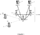
- Figure 1 illustrates in a system level diagram a communication system including a wireless communication system that provides an environment for the application of the principles of the present invention.
- Alternative or additional features not shown in Figure 1 for simplicity include the possibility of an air interface for the X2 link and device to device communications by UEs in different cells or between UEs.
- a UE may be configured to be a "master" device, allocating or adding channels, and collecting loss reports.
- the wireless communication system provides an E-UTRAN architecture including base stations 3 providing E-UTRAN user plane (packet data convergence protocol/radio link control/media access control/physical transport) and control plane (radio resource control) protocol terminations directed towards UEs 5.
- the base stations 3 are interconnected with an X2 interface or communication link.
- the base stations 3 are also connected by an S 1 interface or communication link to an evolved packet core ("EPC") including, for instance, a mobility management entity (“MME”) and a user plane entity (“UPE”) 1, which may form an access gateway (“aGW').
- EPC evolved packet core
- MME mobility management entity
- UPE user plane entity
- the S1 interface supports a multiple entity relationship between the mobility management entities/user plane entities and the base stations and supports a functional split between the mobility management entities and the user plane entities.
- the base stations 3 may host functions such as radio resource management, e.g., internet protocol ("IP"), header compression and encryption of user data streams, ciphering of user data streams, radio bearer control, radio admission control, connection mobility control, and dynamic allocation of resources to user equipment in both the uplink and the downlink, selection of a mobility management entity at the user equipment attachment, routing of user plane data towards the user plane entity, scheduling and transmission of paging messages (originated from the mobility management entity 1), scheduling and transmission of broadcast information (originated from the mobility management entity or operations and maintenance), and measurement and reporting configuration for mobility and scheduling.
- radio resource management e.g., internet protocol (“IP")
- IP internet protocol
- header compression and encryption of user data streams e.g., header compression and encryption of user data streams
- ciphering of user data streams e.g., radio bearer control
- radio admission control e.g., connection mobility control
- the mobility management entity/user plane entity 1 may host functions such as distribution of paging messages to the base stations, security control, terminating user plane ("U-plane") packets for paging reasons, switching of U-plane for support of the user equipment mobility, idle state mobility control, and system architecture evolution bearer control.
- the user equipment receives an allocation of a group of information blocks from the base stations.
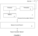
- FIG. 2 illustrates a simplified system level diagram of an example communication element of a communication system that provides an environment and structure for application of the principles of the present invention.
- the communication element 7 may represent, without limitation, an apparatus including a base station or NB, UE such as a terminal or mobile station.
- the communication element includes, at least, a processor 2, memory 6 that stores programs and data of a temporary or more permanent nature, an antenna, and a radio frequency transceiver 4 coupled to the antenna and the processor for bidirectional wireless communication. Other functions may also be provided.
- the communication element may provide point-to-point and/or point-to-multipoint communication services.
- the communication element 7, such as a base station in a cellular network, may be coupled to a network element 9, such as a network control element of a telecommunication network.
- the network control element 9 may, in turn, be formed with a processor, memory, and other electronic elements (not shown).
- the network control element 9 generally provides access to a telecommunication network such as a public switched telecommunication network ("PSTN"). Access may be provided using fiber optic, coaxial, twisted pair, microwave communication, or similar communication links coupled to an appropriate link-terminating element.
- PSTN public switched telecommunication network
- a communication element 7 formed as a mobile station is generally a self-contained device intended to be carried by an end user; however in areas where wired services are not available the mobile station may be permanently installed at a fixed location as well.
- the processor 2 in the communication element 7, which may be implemented with one or a plurality of processing devices, performs functions associated with its operation including, without limitation, encoding and decoding of individual bits forming a communication message, formatting of information, and overall control of the communication element, including processes related to management of resources.
- Exemplary functions related to management of resources include, without limitation, hardware installation, traffic management, performance data analysis, tracking of end users and mobile stations, configuration management, end user administration, management of the mobile station, management of tariffs, subscriptions, and billing, and the like.
- the execution of all or portions of particular functions or processes related to management of resources may be performed in equipment separate from and/or coupled to the communication element, with the results of such functions or processes communicated for execution to the communication element.
- the processor 2 of the communication element may be of any type suitable to the local application environment, and may include one or more of general-purpose computers, special-purpose computers, microprocessors, digital signal processors ("DSPs”), and processors based on a multi-core processor architecture, as non-limiting examples.
- general-purpose computers special-purpose computers
- microprocessors microprocessors
- DSPs digital signal processors
- processors based on a multi-core processor architecture, as non-limiting examples.
- the transceiver 4 of the communication element 7 modulates information onto a carrier waveform for transmission by the communication element via the antenna to another communication element.
- the transceiver 4 demodulates information received via the antenna for further processing by other communication elements.
- the memory 6 of the communication element 7, as introduced above, may be of any type suitable to the local application environment, and may be implemented using any suitable volatile or non-volatile data storage technology, such as a semiconductor-based memory device, a magnetic memory device and system, an optical memory device and system, fixed memory, and removable memory.
- the programs stored in the memory 6 may include program instructions that, when executed by an associated processor 2, enable the communication element 7 to perform tasks as described herein.
- Exemplary embodiments of the system, subsystems, and modules as described herein may be implemented, at least in part, by computer software executable by processors of, for instance, the mobile station and the base station, or by hardware, or by combinations thereof. Other programming may be used such as firmware and/or state machines.
- systems, subsystems and modules may be embodied in the communication element 7 as illustrated and described above.
- FIG. 3 depicts a block diagram of an embodiment of user equipment 5 and a base station 3 constructed according to the principles of the present invention.
- the user equipment UE 5 and the base station eNB 3 each include a variety of layers and subsystems: the physical layer (“PHY”) subsystem, a medium access control layer (“MAC”) subsystem, a radio link control layer (“RLC”) subsystem, a packet data convergence protocol layer (“PDCP”) subsystem, and a radio resource control layer (“RRC”) subsystem.
- PHY physical layer
- MAC medium access control layer
- RLC radio link control layer
- PDCP packet data convergence protocol layer
- RRC radio resource control layer
- the user equipment 5 and the mobile management entity (“MME”) 1 include a non-access stratum (“NAS”) subsystem.
- NAS non-access stratum
- the physical layer subsystem supports the physical transport of packets over the LTE air interface and provides, as non-limiting examples, CRC insertion, e.g., a 24 bit CRC is a baseline for physical downlink shared channel (“PDSCH”), channel coding, hybrid asynchronous retransmit request (“HARQ”) processing, and channel interleaving.
- CRC insertion e.g., a 24 bit CRC is a baseline for physical downlink shared channel (“PDSCH”), channel coding, hybrid asynchronous retransmit request (“HARQ”) processing, and channel interleaving.
- the physical layer subsystem also performs scrambling such as transport-channel specific scrambling on a downlink-shared channel (“DL-SCH”), broadcast channel (“BCH”) and paging channel (“PCH”), as well as closed multicast channel (“MCH”) scrambling for all cells involved in a specific multimedia broadcast multicast service single frequency network (“MBSFN”) transmission.
- DL-SCH downlink-shared channel
- BCH broadcast channel
- the physical layer subsystem also performs signal modulation such as QPSK, 16 QAM and 64 QAM, layer mapping and pre-coding, and mapping to assigned resources and antenna ports.
- the media access layer or MAC performs the HARQ functionality and other important functions between the logical transport layer, or Level 2, and the physical transport layer, or Level 1.
- a layer such as the PHY in the UE 5 may be implemented using hardware, software, programmable hardware, firmware, or a combination of these as is known in the art.
- Programmable devices such as DSPs, reduced instruction set (“RISC”), complete instruction set (“CISC”), microprocessors, microcontrollers, and the like may be used to perform the functions of a layer.
- Reusable design cores or macros as are provided by vendors as ASIC library functions, for example, may be created to provide some or all of the functions and these may be qualified with various semiconductor foundry providers to make design of new UEs, or eNode B implementations, faster and easier to perform in the design and commercial production of new devices.
- Figure 4 depicts an example illustrative environment for application of the embodiments.
- neighboring HeNBs 40, 41, 42 and 43 correspond to an HeNB #0, #1, #2 and #3 that may interfere with one another (users connected over an air interface to one of these stations may experience interference due to the use of the air interface by user equipment communicating with another one of these stations).
- the base stations are shown as HeNBs, the embodiments are not so limited and have application in any communications system where base stations serving a local area may interfere with neighboring base stations when channels are added, the embodiments have particular application to systems using femtocells, HeNBs, microcells and the like.
- a UE may be configured to act as a base station or HeNB itself, allowing local devices to access the network using the UE as the eNB, and in this case the UE is a master device with all of the features of the HeNB described above.
- UEs 51 are communicating with and serviced by HeNB #0, number 40 in the figure.
- UE 53 is one of the UEs communicating with HeNB#1, number 41 in the figure.
- UE 55 is communicating with HeNB#3, number 43 in the figure, and
- UE 57 is communicating with HeNB#2, numbered 42 in the figure.
- HeNB#0 wants to add a channel "c" to add capacity for service in its local cell. Adding this channel will cause interference in the remaining cells served by HeNB#1, HeNB#2, and HeNB#3 if the same channel is in use in those cells.
- the figure illustrates messages between the UEs and the associated HeNB in each of the cell areas, and communication between the HeNBs, as will be further described below.
- Embodiments of the present invention provide alternative algorithms, methods and implementations for providing carrier aggregation for HeNBs or similar local area base station equipment in a radio frequency signaling system.
- These base stations are typically used to add cellular services to a building, home, office, campus or other small local area where users with similar needs for services may congregate.
- these base stations sometimes called “femto-cells” are designed to serve user equipments in a limited physical area; for example, a service local area with a radius of 30 or 50 meters.
- the user equipments will often have a common resource allocation, that is, a "whitelist” or "closed subscriber group” may be used to decide which UEs can connect to the base station.
- members of a household may permanently register their UEs with the HeNB for their home, so that the base station knows these devices and allows access, while UEs that happen to be in physical proximity that are not part of the group are not allowed to connect to the HeNB.
- the base station knows these devices and allows access, while UEs that happen to be in physical proximity that are not part of the group are not allowed to connect to the HeNB.
- interference between channels used by one such device and the neighboring cells will occur.
- Embodiments of the present invention provide methods and apparatuses for facilitating a distributed channel assignment scheme for local area base station environments.
- an HeNB for example
- it causes interference to neighboring cells where the channel is already in use.
- the HeNB trying to add the new channel will measure the average capacity gain estimated for its own cell UEs, and then compare the gain with the capacity loss reported from the neighboring HeNBs when the new channel is added.
- a loss report is generated, which contains the capacity loss by the UE experiencing the worst channel conditions in each of the neighboring cell(s).
- the channel is added.
- Other predetermined thresholds or decision points could be used as alternatives to the simple "greater than” threshold for the decision.
- the number of neighbor cells to be considered can be limited to a certain number.
- the gain and loss measurements can be averaged, scaled by a certain factor, or otherwise evaluated.
- the "sums" for gains and losses as used in this description need not be limited to a simple arithmetic sum, as alternatives contemplated as additional embodiments, weighting or scaling factors may be used, or some other arithmetic or statistical factors may be applied, so that additional considerations may be taken into account.
- HeNB#0 desires to add a new channel 'c' to its cell.
- the UEs 51 attached to and serviced by this HeNB then report the increased capacity gain to HeNB#0.
- the increase in capacity can be estimated, for example, by channel quality indicators reported by the UE for the new channel 'c'.
- the HeNBs#l, #2 and #3 in each case generate a loss report that is communicated back to HeNB#0.
- HeNBs#1, #2 and #3 can estimate the loss in capacity.
- HeNB#0 may compare the gain in capacity by its UEs due to the new channel to the loss in capacity in the neighboring cells, and determine whether the gain is greater than the loss.
- the increase or decrease in SINR can be compared in the cell serviced by HeNB#0 due to the added channel to the SINR in the neighboring cells, or a look up table containing channel quality indicator information, SINR information, or loss reports previously stored may be used.
- the average capacity increase of cell users served by the HeNB that intends to add the channel is compared with the loss of capacity experienced by the "J" worst users in the interfered neighboring cells.
- the number of neighboring cells to be considered can be limited to make the necessary calculations reasonable, so that the time required is kept short and system resources are not overburdened.
- Using the worst users in the neighboring cells for the capacity loss estimate emphasizes the performance of heavy interfered users and should ensure that they are do not experience a service outage.
- the sum or other selected measure of the losses experienced by the user experiencing the worst channel conditions in the newly added channel in the neighboring cells is used in certain embodiments. In certain embodiments the 'J' users experiencing the highest capacity loss are considered.
- This sum or other loss measure is compared with the capacity gain experienced by users of the HeNB adding the channel, and a comparison is used in the decision making process that decides whether to add the channel.
- communication between HeNBs is performed. This can be done through the network, by a network manager, or in some instances, over the air interface directly or relayed by user equipments.
- the channel quality indicator estimates used are measured by UEs before, and again after, the new channel is added.
- the channel quality indicator (“CQI") can be an SINR estimate, a RSRQ or similar.
- the CQI estimates are sent back to the HeNBs.
- the HeNBs estimate the capacity loss based on the CQI reported on each of the channels for all the UEs.
- the average gain value is also estimated based on similar measurements reported by UEs for the particular HeNB trying to add the channel. Based on a comparison of the capacity gained by the particular HeNB to the capacity lost by the neighboring cells, a decision is made on whether to keep the added channel.
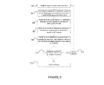
- a method embodiment is illustrated as a flow chart.
- step 61 a determination is made that an additional channel is desired by an HeNB.
- HeNB#0 desires to add a channel
- channel 'c' is used as an non-limiting example.
- step 63 UEs linked to the neighboring HeNBs are asked to report interference experienced on the channel being added.
- step 65 the HeNB adds the new channel 'c'. Further, the UEs and HeNB#0 estimate the average capacity gained by adding the new channel.
- step 67 the UEs connected to each of the neighboring HeNBs, #1-#3, detect the increase in interference experienced on channel 'c'.
- step 69 the neighboring HeNBs, #1-#3 in Figure 4 for example, estimate the loss in capacity for the worst user based on the new and old CQI values, and this loss report is sent to HeNB#0.
- step 71 a decision is made by HeNB#0 based on the comparison of the gain in capacity for users in its own cell area, to the loss of capacity for the neighboring cells. In this example, if the gain is greater than the loss, the method transitions to step 73 and the channel is added by HeNB#0.
- step 71 If the loss by the neighboring cells is greater than the gain, then the channel is dropped in step 75.
- some margin or threshold other than a simple comparison could be used in the decision block.
- the decision could be made not by the HeNB#0, but by a network manager such as an MME, based on receiving the reports from the HeNBs.
- step 69 in Figure 5 different users are considered other than the worst user in the neighboring cells.
- the worst user loss in the neighboring cell is used if and only if the newly added channel was the best channel for that worst user before the assignment was done. If the newly added channel was not the best channel for the worst user in the neighboring cell, then the worst user loss is ignored, and instead the second worst user loss is reported by the neighboring cells. Since the channel being added in the neighboring cell was not the best channel for that worst user, the scheduler will not in fact schedule that channel for that user. Thus, ignoring the impact on that user of adding the new channel will not cause any impact on the capacity for that user. Instead, the second worst user is evaluated.
- the algorithm might consider a set of worst users with highest capacity loss on the channel or worst overall CQI estimate.
- the second worst user may be a set of second worst users. The loss and gain of users may be averaged, normalized or scaled.
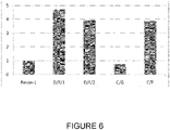
- this embodiment gives 4 times the 5th percentile throughput ( Figure 6 ) with a 4% gain in the mean throughput value, as shown in Figure 7 .
- the performance of the embodiments is at par with the prior ACCS approach, with lower system complexity, lesser amount of statistical data collection required for decision-making and without the assumption of any a priori knowledge of target SINR values. This makes the system utilizing the embodiments much simpler to implement, lower in cost, and keeps the decision making process fast.
- the study also compared the embodiments to a centralized greedy (C/G) scheme.
- This centralized approach assumes the presence of a centralized entity that makes channel assignment which maximizes the mean throughput in each building.
- a centralized fair (C/F) scheme is also studied in which the centralized entity goes for a channel allocation which maximizes the throughput of the worst user in each cell in a building.
- the curves labeled C/G and C/F in each of Figures 6 and 7 present the results. This comparison is helpful to compare the lower percentile and mean throughput values of the embodiments to a centralized entity approach.
- the embodiments may be implemented as hardware, software, firmware, or combinations of these.
- the embodiments may be provided as executable code stored in a machine readable form.
- the embodiments may be applied to any application where aggregating carriers in base stations serving local areas that may have interference with neighboring base stations is applicable.
- a method comprises: determining in a base station servicing user equipments in a local area in an over the air interface for communications at a radio frequency that an additional channel is needed, receiving reports from user equipment connected to the base station over the air interface indicating the gain in capacity that would occur due to the added channel, adding the new channel and communicating to one or more user equipments over the new channel; receiving loss reports from one or more neighboring base stations indicating the loss in capacity and the interference caused to user equipments serviced by the neighboring base stations due to the use of the new channel; comparing the gain in capacity by the user equipments connected to the base station to the loss of capacity by the user equipments connected to the neighboring base stations due to the added channel; and based on the comparison, determining whether to continue to add the channel to increase capacity.
- the above method steps are performed wherein the determining is based on whether the added capacity is greater than the sum of the lost capacity from each of the neighboring cells user equipments with the highest loss reports.
- an apparatus comprises at least one processor; and at least one memory including computer program code, the at least one memory and the computer program code configured to, with the at least one processor, cause the apparatus at least to perform determining that an additional channel is needed for a base station servicing user equipments over an air interface in a local area, receiving reports from user equipment connected to the base station over the air interface indicating the gain in capacity that would occur due to the added channel, adding the new channel and communicating to one or more of the user equipments over the new channel; receiving loss reports from one or more neighboring base stations each servicing a local area indicating the loss in capacity and the interference caused to user equipments serviced by the neighboring base stations due to the use of the new channel; comparing the gain in capacity by the user equipments connected to the base station to the loss of capacity by the worst user connected to the neighboring base stations due to the use of the newly added channel; and based on the comparison, determining whether to continue to add the channel to increase capacity.
- the at least one processor; and at least one memory including computer program code, the at least one memory and the computer program code configured to, with the at least one processor, cause the apparatus at least to perform the above steps wherein the determining is based on whether the added capacity is greater than the sum of the lost capacity from each of the neighboring cells worst user reports.
- a computer program product comprising a program code stored in a tangible form in a computer readable medium, configured to cause an apparatus comprising at least one processor and at least one memory to at least perform: determining that an additional channel is needed for a base station servicing user equipments over an air interface in a local area, receiving reports from user equipment connected to the base station over the air interface indicating the gain in capacity that would occur due to the added channel, adding the new channel and communicating to one or more of the user equipments over the new channel; receiving loss reports from one or more neighboring base stations each servicing a local area indicating the loss in capacity and the interference caused to user equipments serviced by the neighboring base stations due to the use of the new channel; comparing the gain in capacity by the user equipments connected to the base station to the loss of capacity by the worst user connected to the neighboring base stations due to the use of the newly added channel; and based on the comparison, determining whether to continue to add the channel to increase capacity.
- the computer program code computer program code is further configured to, with the at least one processor, cause the apparatus at least to perform the above steps wherein the determining is based on whether the added capacity is greater than the sum of the lost capacity from each of the neighboring cells worst user reports.
- a method comprises: determining in a base station servicing a local area in an over the air interface for communications at a radio frequency that an additional channel is needed, receiving reports from user equipment connected to the base station over the air interface indicating the gain in capacity that would occur due to the added channel, adding the new channel and communicating to one or more user equipments over the new channel; receiving loss reports from one or more neighboring base stations indicating the loss in capacity and the interference caused to user equipments serviced by the neighboring base stations due to the use of the new channel; comparing the gain in capacity by the user equipments connected to the base station to the loss of capacity by the worst user connected to the neighboring base stations due to the added channel if the worst user is likely to use the added channel, otherwise the loss of capacity in each of the neighboring base stations is determined using the second worst user connected to the neighboring base station; and, based on the comparison, determining whether to continue to add the channel to increase capacity.
- the above method steps are performed wherein the determining is based on whether the added
- an apparatus comprises at least one processor; and at least one memory including computer program code, the at least one memory and the computer program code configured to, with the at least one processor, cause the apparatus at least to perform determining in a base station servicing user equipments in a local area in an over the air interface for communications at a radio frequency that an additional channel is needed, receiving reports from user equipment connected to the base station over the air interface indicating the gain in capacity that would occur due to the added channel, adding the new channel and communicating to one or more user equipments over the new channel; receiving loss reports from one or more neighboring base stations indicating the loss in capacity and the interference caused to user equipments serviced by the neighboring base stations due to the use of the new channel; comparing the gain in capacity by the user equipments connected to the base station to the loss of capacity by the set of users with the highest loss in capacity connected to the neighboring base stations due to the added channel if the added channel was part of the best set of channels for one or more of this set of users, otherwise the loss of capacity in each of the neighboring base stations is
- a method comprises: determining in a base station servicing a plurality of user equipments in a local area in an over the air interface for communications at a radio frequency that an additional channel is needed, receiving reports from user equipment connected to the base station over the air interface indicating the gain in capacity that would occur due to the added channel, adding the new channel and communicating to one or more user equipments over the new channel; receiving loss reports from one or more neighboring base stations indicating the loss in capacity and the interference caused to user equipments serviced by the neighboring base stations due to the use of the new channel; comparing the gain in capacity by the user equipments connected to the base station to the loss of capacity by the worst user equipments obtained by averaging the loss suffered by a selected set of user equipments, considering changes in CQI, alternatively considering changes in SINR and or other interference or reception indicators.
- the averaged loss may be compared to a threshold, to the gain in the cell serviced by the UE adding the channel, or to other criteria.
- the method continues by determining whether to continue to add the channel to increase capacity based on the comparison, if the gain exceeds a criteria over the averaged loss experienced due to the added interference, the added channel is retained; otherwise, it is not.
- a method comprises: determining in a base station servicing a local area in an over the air interface for communications at a radio frequency that an additional channel is needed, receiving reports from user equipment connected to the base station over the air interface indicating the gain in capacity that would occur due to the added channel, adding the new channel and communicating to one or more user equipments over the new channel; receiving loss reports from one or more neighboring base stations indicating the loss in capacity and the interference caused to user equipments serviced by the neighboring base stations due to the use of the new channel; comparing the gain in capacity by the user equipments connected to the base station to the loss of capacity by the worst user equipments obtained by averaging the loss suffered by a selected set of user equipments, considering changes in CQI, alternatively considering changes in SINR and or other interference or reception indicators.
- the averaged loss may be compared to a threshold, to the gain in the cell serviced by the UE adding the channel, or to other criteria.
- each user, or some selected users in each cell are checked to ensure a minimum SINR is obtained after the newly added channel is used. This ensures that the added channel will not reduce SINR in a neighboring cell to a level below a minimum required SINR for acceptable communication.
- the then method continues by determining whether to continue to add the channel to increase capacity based on the comparison, if the gain exceeds a criteria over the averaged loss experienced due to the added interference, and the minimum SINRs are met in the neighboring cells, the added channel is retained; otherwise, it is not.
Abstract
Description
- The present invention is directed, in general, to communication systems and, more particularly, to apparatuses and methods for providing additional capacity for local area communications over an air interface such as may be used with radio frequency communication systems.
- As wireless communication systems such as cellular telephone, satellite, and microwave communication systems become more widely deployed and continue to attract a growing number of users, there is a pressing need to accommodate a large and variable number of communication subsystems transmitting a growing volume of data with a fixed resource such as a fixed channel bandwidth accommodating a fixed data packet size. Traditional communication system designs employing a fixed resource, e.g., a fixed data rate for each user have become challenged to provide high, but flexible, data transmission rates in view of the rapidly growing customer base.
- Current systems implement wireless communications using standard protocols including Universal Mobile Telecommunications System ("UMTS"), UMTS Terrestrial Radio Access Network ("UTRAN"), and third generation wireless ("3G") now extending to advanced standards including, for example, fourth generation wireless ("4G") and Wideband Code Division Multiple Access ("WCDMA") which support HSDPA communications between mobile equipment. The mobile equipment includes user equipment ("UE") such as cell phones, and fixed transceivers that support mobile telephone cells, such as base stations, referred to as "Node B" (or "NB") and when enhanced, or evolved to a new standard protocol, referred to as "e-Node B"(or "eNB").
- The Third Generation Partnership Project Long Term Evolution ("3GPP LTE") is the name generally used to describe an ongoing effort across the industry to improve UMTS. The improvements are being made to cope with continuing new requirements and the growing base of users. Goals of this broadly based project include improving communication efficiency, lowering costs, improving services, making use of new spectrum opportunities, and achieving better integration with other open standards and backwards compatibility with some existing infrastructure that is compliant with earlier standards. Recently, the deployment of systems is extending to "LTE-Advanced" as additional bandwidth and features are added.
- UTRAN includes multiple Radio Network Subsystems ("RNS"), each of which contains at least one Radio Network Controller ("RNC"). However, it should be noted that the RNC may not be present in the actual future implemented systems incorporating Long Term Evolution ("LTE") of UTRAN, evolved UTRAN ("E-UTRAN"). LTE may include a centralized or decentralized entity for control information. In UTRAN operation, each RNC may be connected to multiple Node Bs which are the UMTS counterparts to Global System for Mobile Communications ("GSM") base stations. In E-UTRAN systems, the e-Node B is, or may be, connected directly to the access gateway ("aGW," sometimes referred to as the services gateway "sGW"). Each Node B may be in radio contact with multiple UE devices (generally, user equipment including mobile transceivers or cellular phones, although other devices such as fixed cellular phones, mobile web browsers, tablets, ebook readers, navigation systems, laptops, PDAs, MP3 players, and gaming devices with transceivers may also be UE) via the radio air interface.
- The wireless communication systems as described herein are applicable to, for instance, 3G, and UTRAN systems. In the future, 3GPP LTE and LTE-A compatible wireless communication systems will be implemented. In general, E-UTRAN resources are assigned by the network to one or more UE devices by use of various resource allocation means, or more generally by use of a downlink resource assignment channel or physical downlink control channel ("PDCCH"). LTE is a packet-based system and, therefore, there may not be a dedicated connection reserved for communication between a UE and the network. Users are generally scheduled on a shared channel every transmission time interval ("TTI") by a Node B or an e-Node B. A Node B or an e-Node B controls the communications between user equipment terminals in a cell served by the Node B or e-Node B. In general, one Node B or e-Node B serves each cell. Resources needed for data transfer are assigned either as one time assignments or in a persistent/semi-static way. The LTE, also referred to as 4G, generally supports a large number of users per cell with quasi-instantaneous access to radio resources in the active state.
- The continuing need for additional spectrum/bandwidth is being addressed in various ways. In one approach to adding broadband spectrum, additional base stations for communications with user equipment are deployed. These may include so-called "femto-cells" or "Home enhanced Node B" stations, sometimes called "HeNBs". A HeNB may provide wireless interface to user equipment in a home, office, restaurant or other space where the users may share the resource. The user equipment devices may include cellular phones, PDAs, tablet computers, laptop computers, portable or fixed devices such as web browsers, audio players, video players and others. The area serviced by a femtocell or HeNB may be, for example, limited to 30 to 50 meters in radius. The advantages of deploying these base stations is that the users may experience excellent signal quality in the home or office, reducing or eliminating the need for wired telephones for example, and making it possible to rely on a cellular phone in buildings where previously, signal strength and reception were not sufficient. Additional bandwidth is also provided for the system, reducing the need for the eNB base station in the area to provide all of the wireless service. It is also envisioned that user equipment ("UE") can act as a HeNB.
- One aspect of HeNB deployment is that, in contrast to the deployment of system managed base stations, the placement of new HeNBs is uncoordinated and may be performed by users. The HeNBs may be placed in very close physical proximity, such as installed in homes adjacent one another, in offices, apartments, townhomes and the like. A particular user equipment may therefore often be physically closer to a neighboring HeNB than the HeNB the user device is in cellular communication with, and interference between the HeNB cells will occur.
- Multiple uncoordinated deployed HeNBs may operate on the same frequency band. Some of these networks may provide services not available from other HeNBs. The HeNBs and users may utilize closed subscriber groups ("CSGs"). A user interested in using these services may be physically closer to, or in better signaling receiving condition with, an interfering HeNB, instead of the HeNB of interest.
- Typically, a frequency band has multiple channels and the HeNB operates on one of these channels. Ideally, HeNBs causing strong interference to one another are placed on different channels. There are several known approaches to the interference problem. In one distributed approach, HeNBs try to maximize the path loss to other HeNBs sharing the same frequency channel. In an alternative approach, a centralized scheme is known where the HeNBs report measurements to a network node, and the network node then assigns the channels in a manner that will reduce interference between HeNBs.
- If an HeNB could utilize carrier aggregation, then additional capacity could be accessed by an HeNB. However, present releases of known standards do not contemplate carrier aggregation for HeNBs, for example Release 10 of the LTE standard does not allow carrier aggregation for HeNBs. Thus far, the interference coordination schemes in the known standard approaches have been limited to coordinate the interference with co-channel deployments of macro-cells.
- An approach to address the interference that has been previously described in "Interference Management in Local Area Environments for LTE-Advanced," L.G.U. Garcia, K.I. Pedersen, and P.E. Mogensen, IEEE Communications Magazine, Vol. 47 (9):110-116, September 2009, which is hereby incorporated herein by reference in its entirety; as an autonomous component carrier selection scheme ("ACCS"). In this scheme, dynamic frequency reuse mechanisms are used. Each HeNB selects a subset of available component carriers in a distributed manner. The HeNBs also learn the environment using signal to interference plus noise ("SINR") estimates provided by active user equipment. The UEs measure the downlink received signals (from HeNB to UE) as part of normal system operations and these estimates may be collected. Based on long term statistics collected, SINR values are determined for all neighboring cells which can be considered as potential interferers. The proposed ACCS scheme also has the HeNBs or the network storing the environment information, for example, in background information matrices ("BIM") which are used later in the channel selection decision process.
- In the ACCS scheme, it is proposed that each HeNB will maintain a list of potentially interfering cells. Also, the eNB measurements are aggregated into a table form; for example, an inter-cell radio resource allocation table ("RRAT"). This table contains information regarding which component carriers are allocated as primary and secondary carriers in the cells. Based on the information stored in the BIMs and the RRAT, the HeNBs do carrier selection in a distributed manner without violating the minimum SINR conditions for surrounding cells. One of the main assumptions in this prior scheme is the a priori knowledge of minimum target SINR values for primary and secondary carriers. These target SINR requirements can be set, for example, by a network planning tool or by the administering device such as an Operations and Maintenance tool which controls the HeNBs. The ACCS scheme is described also, for example, in a paper entitled "Autonomous Component Carrier Selection for Local Area Uncoordinated Deployment of LTE-Advanced," L.G.U. Garcia, K.I. Pedersen, and P.E. Mogensen, IEEE Vehicular Technology Conference (VTC), Anchorage Alaska, USA September 2009, which is hereby incorporated herein by reference in its entirety.
- In future standards, such as future LTE-Advanced standards, it is foreseen that the use of carrier aggregation will be supported for HeNBs. Further, it is also clear that if the HeNBs are deployed with similar density as for wireless hotspots ("Wi-Fi" access points) then some interference management between deployed HeNBs will be needed.
- A need thus exists for systems and methods to efficiently provide carrier aggregation and interference management for local area base stations such as HeNBs for cellular communications, without the disadvantages of the known prior approaches.
- These and other problems are generally solved or circumvented, and technical advantages are generally achieved, by advantageous embodiments of the present invention which include an apparatus and methods for providing the UE observed time difference measurements needed for location services.
- According to an illustrative embodiment, a method comprises: determining in a base station servicing a local area in an over the air interface for communications at a radio frequency that an additional channel is needed, receiving reports from user equipment connected to the base station over the air interface indicating the gain in capacity that would occur due to the added channel, adding the new channel and communicating to one or more user equipments over the new channel; receiving loss reports from one or more neighboring base stations indicating the loss in capacity and the interference caused to user equipments serviced by the neighboring base stations due to the use of the new channel; comparing the gain in capacity by the user equipments connected to the base station to the loss of capacity by the worst user connected to the neighboring base stations due to the added channel; and based on the comparison, determining whether to continue to add the channel to increase capacity.
- In another embodiment, an apparatus comprises: at least one processor; and at least one memory including computer program code, the at least one memory and the computer program code configured to, with the at least one processor, cause the apparatus at least to perform determining that an additional channel is needed for a base station servicing user equipments over an air interface in a local area, receiving reports from user equipment connected to the base station over the air interface indicating the gain in capacity that would occur due to the added channel, adding the new channel and communicating to one or more of the user equipments over the new channel; receiving loss reports from one or more neighboring base stations each servicing a local area indicating the loss in capacity and the interference caused to user equipments serviced by the neighboring base stations due to the use of the new channel; comparing the gain in capacity by the user equipments connected to the base station to the loss of capacity by the worst user connected to the neighboring base stations due to the use of the newly added channel; and based on the comparison, determining whether to continue to add the channel to increase capacity.
- The foregoing has outlined rather broadly the features and technical advantages of the present invention in order that the detailed description of the invention that follows may be better understood. Additional features and advantages of the invention will be described hereinafter which form the subject of the claims of the invention. It should be appreciated by those skilled in the art that the conception and specific embodiment disclosed may be readily utilized as a basis for modifying or designing other structures or processes for carrying out the same purposes of the present invention. It should also be realized by those skilled in the art that such equivalent constructions do not depart from the spirit and scope of the invention as set forth in the appended claims.
- For a more complete understanding of the invention, and the advantages thereof, reference is now made to the following descriptions taken in conjunction with the accompanying drawing, in which:
-
Figure 1 illustrates a communications system according to an advantageous embodiment of the present invention; -
Figure 2 illustrates user equipment communicating to an eNode B over an air interface, and an E-UTRAN communications system according to an advantageous embodiment of the present invention; -
Figure 3 illustrates a block diagram of a communication terminal according to an advantageous embodiment of the present invention; -
Figure 4 illustrates an example illustrative system for use with the embodiments; -
Figure 5 illustrates a method embodiment in a flow chart diagram; -
Figure 6 illustrates a graph comparing user throughput cumulative distribution function results obtained using embodiments with other carrier allocation schemes; and -
Figure 7 illustrates a graph comparing mean throughput results obtained using the embodiments to other carrier allocation schemes. -
Figure 1 illustrates in a system level diagram a communication system including a wireless communication system that provides an environment for the application of the principles of the present invention. Alternative or additional features not shown inFigure 1 for simplicity include the possibility of an air interface for the X2 link and device to device communications by UEs in different cells or between UEs. In one example, a UE may be configured to be a "master" device, allocating or adding channels, and collecting loss reports. The wireless communication system provides an E-UTRAN architecture includingbase stations 3 providing E-UTRAN user plane (packet data convergence protocol/radio link control/media access control/physical transport) and control plane (radio resource control) protocol terminations directed towardsUEs 5. Thebase stations 3 are interconnected with an X2 interface or communication link. Thebase stations 3 are also connected by anS 1 interface or communication link to an evolved packet core ("EPC") including, for instance, a mobility management entity ("MME") and a user plane entity ("UPE") 1, which may form an access gateway ("aGW'). The S1 interface supports a multiple entity relationship between the mobility management entities/user plane entities and the base stations and supports a functional split between the mobility management entities and the user plane entities. - The
base stations 3 may host functions such as radio resource management, e.g., internet protocol ("IP"), header compression and encryption of user data streams, ciphering of user data streams, radio bearer control, radio admission control, connection mobility control, and dynamic allocation of resources to user equipment in both the uplink and the downlink, selection of a mobility management entity at the user equipment attachment, routing of user plane data towards the user plane entity, scheduling and transmission of paging messages (originated from the mobility management entity 1), scheduling and transmission of broadcast information (originated from the mobility management entity or operations and maintenance), and measurement and reporting configuration for mobility and scheduling. The mobility management entity/user plane entity 1 may host functions such as distribution of paging messages to the base stations, security control, terminating user plane ("U-plane") packets for paging reasons, switching of U-plane for support of the user equipment mobility, idle state mobility control, and system architecture evolution bearer control. The user equipment receives an allocation of a group of information blocks from the base stations. -
Figure 2 illustrates a simplified system level diagram of an example communication element of a communication system that provides an environment and structure for application of the principles of the present invention. Thecommunication element 7 may represent, without limitation, an apparatus including a base station or NB, UE such as a terminal or mobile station. The communication element includes, at least, aprocessor 2,memory 6 that stores programs and data of a temporary or more permanent nature, an antenna, and aradio frequency transceiver 4 coupled to the antenna and the processor for bidirectional wireless communication. Other functions may also be provided. The communication element may provide point-to-point and/or point-to-multipoint communication services. - The
communication element 7, such as a base station in a cellular network, may be coupled to anetwork element 9, such as a network control element of a telecommunication network. Thenetwork control element 9 may, in turn, be formed with a processor, memory, and other electronic elements (not shown). Thenetwork control element 9 generally provides access to a telecommunication network such as a public switched telecommunication network ("PSTN"). Access may be provided using fiber optic, coaxial, twisted pair, microwave communication, or similar communication links coupled to an appropriate link-terminating element. Acommunication element 7 formed as a mobile station is generally a self-contained device intended to be carried by an end user; however in areas where wired services are not available the mobile station may be permanently installed at a fixed location as well. - The
processor 2 in thecommunication element 7, which may be implemented with one or a plurality of processing devices, performs functions associated with its operation including, without limitation, encoding and decoding of individual bits forming a communication message, formatting of information, and overall control of the communication element, including processes related to management of resources. Exemplary functions related to management of resources include, without limitation, hardware installation, traffic management, performance data analysis, tracking of end users and mobile stations, configuration management, end user administration, management of the mobile station, management of tariffs, subscriptions, and billing, and the like. The execution of all or portions of particular functions or processes related to management of resources may be performed in equipment separate from and/or coupled to the communication element, with the results of such functions or processes communicated for execution to the communication element. Theprocessor 2 of the communication element may be of any type suitable to the local application environment, and may include one or more of general-purpose computers, special-purpose computers, microprocessors, digital signal processors ("DSPs"), and processors based on a multi-core processor architecture, as non-limiting examples. - The
transceiver 4 of thecommunication element 7 modulates information onto a carrier waveform for transmission by the communication element via the antenna to another communication element. Thetransceiver 4 demodulates information received via the antenna for further processing by other communication elements. - The
memory 6 of thecommunication element 7, as introduced above, may be of any type suitable to the local application environment, and may be implemented using any suitable volatile or non-volatile data storage technology, such as a semiconductor-based memory device, a magnetic memory device and system, an optical memory device and system, fixed memory, and removable memory. The programs stored in thememory 6 may include program instructions that, when executed by an associatedprocessor 2, enable thecommunication element 7 to perform tasks as described herein. Exemplary embodiments of the system, subsystems, and modules as described herein may be implemented, at least in part, by computer software executable by processors of, for instance, the mobile station and the base station, or by hardware, or by combinations thereof. Other programming may be used such as firmware and/or state machines. As will become more apparent, systems, subsystems and modules may be embodied in thecommunication element 7 as illustrated and described above. -
Figure 3 depicts a block diagram of an embodiment ofuser equipment 5 and abase station 3 constructed according to the principles of the present invention. Theuser equipment UE 5 and thebase station eNB 3 each include a variety of layers and subsystems: the physical layer ("PHY") subsystem, a medium access control layer ("MAC") subsystem, a radio link control layer ("RLC") subsystem, a packet data convergence protocol layer ("PDCP") subsystem, and a radio resource control layer ("RRC") subsystem. Additionally, theuser equipment 5 and the mobile management entity ("MME") 1 include a non-access stratum ("NAS") subsystem. - The physical layer subsystem supports the physical transport of packets over the LTE air interface and provides, as non-limiting examples, CRC insertion, e.g., a 24 bit CRC is a baseline for physical downlink shared channel ("PDSCH"), channel coding, hybrid asynchronous retransmit request ("HARQ") processing, and channel interleaving. The physical layer subsystem also performs scrambling such as transport-channel specific scrambling on a downlink-shared channel ("DL-SCH"), broadcast channel ("BCH") and paging channel ("PCH"), as well as closed multicast channel ("MCH") scrambling for all cells involved in a specific multimedia broadcast multicast service single frequency network ("MBSFN") transmission. The physical layer subsystem also performs signal modulation such as QPSK, 16 QAM and 64 QAM, layer mapping and pre-coding, and mapping to assigned resources and antenna ports. The media access layer or MAC performs the HARQ functionality and other important functions between the logical transport layer, or
Level 2, and the physical transport layer, orLevel 1. - Each layer is implemented in the system and may be implemented in a variety of ways. A layer such as the PHY in the
UE 5 may be implemented using hardware, software, programmable hardware, firmware, or a combination of these as is known in the art. Programmable devices such as DSPs, reduced instruction set ("RISC"), complete instruction set ("CISC"), microprocessors, microcontrollers, and the like may be used to perform the functions of a layer. Reusable design cores or macros as are provided by vendors as ASIC library functions, for example, may be created to provide some or all of the functions and these may be qualified with various semiconductor foundry providers to make design of new UEs, or eNode B implementations, faster and easier to perform in the design and commercial production of new devices.Figure 4 depicts an example illustrative environment for application of the embodiments. InFigure 4 , neighboringHeNBs HeNB # 0, #1, #2 and #3 that may interfere with one another (users connected over an air interface to one of these stations may experience interference due to the use of the air interface by user equipment communicating with another one of these stations). While in the exemplary embodiments presented herein for illustrative purposes, the base stations are shown as HeNBs, the embodiments are not so limited and have application in any communications system where base stations serving a local area may interfere with neighboring base stations when channels are added, the embodiments have particular application to systems using femtocells, HeNBs, microcells and the like. In future developments a UE may be configured to act as a base station or HeNB itself, allowing local devices to access the network using the UE as the eNB, and in this case the UE is a master device with all of the features of the HeNB described above. - In
Figure 4 , user equipments ("UEs") 51 are communicating with and serviced byHeNB # 0,number 40 in the figure.UE 53 is one of the UEs communicating withHeNB# 1,number 41 in the figure. Similarly,UE 55 is communicating withHeNB# 3,number 43 in the figure, andUE 57 is communicating withHeNB# 2, numbered 42 in the figure. - In this non-limiting example application illustrating the embodiments,
HeNB# 0 wants to add a channel "c" to add capacity for service in its local cell. Adding this channel will cause interference in the remaining cells served byHeNB# 1,HeNB# 2, andHeNB# 3 if the same channel is in use in those cells. The figure illustrates messages between the UEs and the associated HeNB in each of the cell areas, and communication between the HeNBs, as will be further described below. - Embodiments of the present invention provide alternative algorithms, methods and implementations for providing carrier aggregation for HeNBs or similar local area base station equipment in a radio frequency signaling system. These base stations are typically used to add cellular services to a building, home, office, campus or other small local area where users with similar needs for services may congregate. Typically, these base stations, sometimes called "femto-cells", are designed to serve user equipments in a limited physical area; for example, a service local area with a radius of 30 or 50 meters. In the local area the user equipments will often have a common resource allocation, that is, a "whitelist" or "closed subscriber group" may be used to decide which UEs can connect to the base station. As one non-limiting example, members of a household may permanently register their UEs with the HeNB for their home, so that the base station knows these devices and allows access, while UEs that happen to be in physical proximity that are not part of the group are not allowed to connect to the HeNB. However, due to the proximity of multiple ones of such devices with respect to each other, interference between channels used by one such device and the neighboring cells will occur.
- Embodiments of the present invention provide methods and apparatuses for facilitating a distributed channel assignment scheme for local area base station environments. In the embodiments, when an HeNB (for example) attempts to add a new channel to its services, it causes interference to neighboring cells where the channel is already in use. In the embodiments, the HeNB trying to add the new channel will measure the average capacity gain estimated for its own cell UEs, and then compare the gain with the capacity loss reported from the neighboring HeNBs when the new channel is added. A loss report is generated, which contains the capacity loss by the UE experiencing the worst channel conditions in each of the neighboring cell(s). In an embodiment, if the capacity gain experienced by the HeNBs own UEs is greater than the summed capacity loss experienced by UEs in neighboring cells, the channel is added. Other predetermined thresholds or decision points could be used as alternatives to the simple "greater than" threshold for the decision. In an example embodiment, the number of neighbor cells to be considered can be limited to a certain number. The gain and loss measurements can be averaged, scaled by a certain factor, or otherwise evaluated. The "sums" for gains and losses as used in this description need not be limited to a simple arithmetic sum, as alternatives contemplated as additional embodiments, weighting or scaling factors may be used, or some other arithmetic or statistical factors may be applied, so that additional considerations may be taken into account. These alternatives may allow for faster calculation or for additional information to be included without treating each UE in each neighbor cell individually. In any event, if the gain accomplished gives better performance than the losses due to the added channel, the new channel is added or retained. But, in contrast, if the gain is less than the capacity loss experienced in neighboring cells, the new channel is not added, or is dropped. Thus, the channel is only added by the HeNB in the example application if the overall system capacity is increased; if not, then the new channel is dropped.
- Returning to
Figure 4 , which depicts an exemplary system for use with the embodiments, the example situation is depicted. InFigure 4 ,HeNB# 0, numbered 40, desires to add a new channel 'c' to its cell. TheUEs 51 attached to and serviced by this HeNB then report the increased capacity gain toHeNB# 0. The increase in capacity can be estimated, for example, by channel quality indicators reported by the UE for the new channel 'c'. After the new channel is added, each of the neighboring basestations HeNB# 1,HeNB# 2 andHeNB# 3, numbered 41, 42 and 43 respectively, also receive/ask for reports from their connected UEs of the interference experienced due to the new use of channel 'c' byHeNB# 0, or receive a channel quality indicator feedback. The HeNBs#l, #2 and #3 in each case generate a loss report that is communicated back toHeNB# 0. By comparing the feedback with the reported channel quality indicators that were received beforeHeNB# 0 added the channel,HeNBs# 1, #2 and #3 can estimate the loss in capacity. ThenHeNB# 0 may compare the gain in capacity by its UEs due to the new channel to the loss in capacity in the neighboring cells, and determine whether the gain is greater than the loss. In alternative embodiments, instead of comparing gain and loss in capacity, the increase or decrease in SINR can be compared in the cell serviced byHeNB# 0 due to the added channel to the SINR in the neighboring cells, or a look up table containing channel quality indicator information, SINR information, or loss reports previously stored may be used. - In embodiments implementing the methods of the invention, the average capacity increase of cell users served by the HeNB that intends to add the channel is compared with the loss of capacity experienced by the "J" worst users in the interfered neighboring cells. The number of neighboring cells to be considered can be limited to make the necessary calculations reasonable, so that the time required is kept short and system resources are not overburdened. Using the worst users in the neighboring cells for the capacity loss estimate emphasizes the performance of heavy interfered users and should ensure that they are do not experience a service outage. The sum or other selected measure of the losses experienced by the user experiencing the worst channel conditions in the newly added channel in the neighboring cells is used in certain embodiments. In certain embodiments the 'J' users experiencing the highest capacity loss are considered. This sum or other loss measure is compared with the capacity gain experienced by users of the HeNB adding the channel, and a comparison is used in the decision making process that decides whether to add the channel. In order to make the comparison, communication between HeNBs is performed. This can be done through the network, by a network manager, or in some instances, over the air interface directly or relayed by user equipments.
- In an exemplary method embodiment, the channel quality indicator estimates used are measured by UEs before, and again after, the new channel is added. The channel quality indicator ("CQI") can be an SINR estimate, a RSRQ or similar. The CQI estimates are sent back to the HeNBs. The HeNBs estimate the capacity loss based on the CQI reported on each of the channels for all the UEs. The average gain value is also estimated based on similar measurements reported by UEs for the particular HeNB trying to add the channel. Based on a comparison of the capacity gained by the particular HeNB to the capacity lost by the neighboring cells, a decision is made on whether to keep the added channel.
- In
Figure 5 , a method embodiment is illustrated as a flow chart. Instep 61, a determination is made that an additional channel is desired by an HeNB. In this example,HeNB# 0 desires to add a channel, channel 'c' is used as an non-limiting example. Instep 63, UEs linked to the neighboring HeNBs are asked to report interference experienced on the channel being added. Instep 65, the HeNB adds the new channel 'c'. Further, the UEs andHeNB# 0 estimate the average capacity gained by adding the new channel. - The method then transitions to step 67. In
step 67, the UEs connected to each of the neighboring HeNBs, #1-#3, detect the increase in interference experienced on channel 'c'. Instep 69, the neighboring HeNBs, #1-#3 inFigure 4 for example, estimate the loss in capacity for the worst user based on the new and old CQI values, and this loss report is sent toHeNB# 0. Instep 71, a decision is made byHeNB# 0 based on the comparison of the gain in capacity for users in its own cell area, to the loss of capacity for the neighboring cells. In this example, if the gain is greater than the loss, the method transitions to step 73 and the channel is added byHeNB# 0. If the loss by the neighboring cells is greater than the gain, then the channel is dropped instep 75. As alternatives instep 71, some margin or threshold other than a simple comparison could be used in the decision block. Also, the decision could be made not by theHeNB# 0, but by a network manager such as an MME, based on receiving the reports from the HeNBs. - As an alternative approach, in
step 69 inFigure 5 , different users are considered other than the worst user in the neighboring cells. In this alternative embodiment, the worst user loss in the neighboring cell is used if and only if the newly added channel was the best channel for that worst user before the assignment was done. If the newly added channel was not the best channel for the worst user in the neighboring cell, then the worst user loss is ignored, and instead the second worst user loss is reported by the neighboring cells. Since the channel being added in the neighboring cell was not the best channel for that worst user, the scheduler will not in fact schedule that channel for that user. Thus, ignoring the impact on that user of adding the new channel will not cause any impact on the capacity for that user. Instead, the second worst user is evaluated. Please note that instead of a single worst user, the algorithm might consider a set of worst users with highest capacity loss on the channel or worst overall CQI estimate. Further, the second worst user may be a set of second worst users. The loss and gain of users may be averaged, normalized or scaled. - A study was made for the embodiments described above and the approaches were compared with the known prior ACCS proposal described above. The results were that the embodiments had results a bit better than that of the ACCS approach without the need for a priori knowledge of the target SINR values. This aspect of the embodiments provides a simpler implementation and faster performance than would be obtained using the ACCS scheme.
- The scenario used for study of the embodiments is close to the 'extended' scenario defined in the papers incorporated above, but with lower values of spectral efficiency and antenna gains. In
Figure 6 , the user throughput cumulative distribution function ("CDF") curves are compared to a Reuse-1 normalized scheme. InFigure 7 , the mean throughput for each scheme is again compared to a Reuse-1 which is normalized. - As described in the papers, ACCS gives 4 times the 5th percentile throughput compared to Reuse-1 with almost no loss in mean throughput value. For the embodiment where the "worst user" is used for the loss reports to compare the gain to, labeled curve D/F/1, as shown in
Figure 6 , gives 4.5 times the 5th percentile throughput of Reuse-1 with a loss of only 5% in the mean throughput value (also labeled D/F/1, shown inFigure 7 ). For the alternative embodiment where the "second worst" user may be used if the "worst user" would not be assigned the newly added channel, labeled curve D/F/2, this embodiment gives 4 times the 5th percentile throughput (Figure 6 ) with a 4% gain in the mean throughput value, as shown inFigure 7 . - The performance of the embodiments is at par with the prior ACCS approach, with lower system complexity, lesser amount of statistical data collection required for decision-making and without the assumption of any a priori knowledge of target SINR values. This makes the system utilizing the embodiments much simpler to implement, lower in cost, and keeps the decision making process fast.
- The study also compared the embodiments to a centralized greedy (C/G) scheme. This centralized approach assumes the presence of a centralized entity that makes channel assignment which maximizes the mean throughput in each building. A centralized fair (C/F) scheme is also studied in which the centralized entity goes for a channel allocation which maximizes the throughput of the worst user in each cell in a building. The curves labeled C/G and C/F in each of
Figures 6 and7 present the results. This comparison is helpful to compare the lower percentile and mean throughput values of the embodiments to a centralized entity approach. InFigure 6 , it can be seen that the 5th percentile throughput value of the embodiments, curves labeled D/F/1 and D/F/2, is at par with the centralized C/F scheme. FromFigure 7 it can be seen that the embodiment curve D/F/1 has a slight loss of around 6% as compared to the centralized greedy scheme labeled C/G, whereas the alternative embodiment labeled D/F/2 gives mean throughput value slightly better than C/G. From the study results the distributed schemes of the embodiments have a performance very close to the centralized ones, but at a lower cost of implementation. - The embodiments may be implemented as hardware, software, firmware, or combinations of these. For programmable receivers having a processor, microprocessor or the like that is capable of implementing steps of a method stored as computer instructions, the embodiments may be provided as executable code stored in a machine readable form.
- Although the description thus far describes, for illustrative purposes, the use of the embodiments in HeNBs, the embodiments may be applied to any application where aggregating carriers in base stations serving local areas that may have interference with neighboring base stations is applicable.
- In an embodiment, a method comprises: determining in a base station servicing user equipments in a local area in an over the air interface for communications at a radio frequency that an additional channel is needed, receiving reports from user equipment connected to the base station over the air interface indicating the gain in capacity that would occur due to the added channel, adding the new channel and communicating to one or more user equipments over the new channel; receiving loss reports from one or more neighboring base stations indicating the loss in capacity and the interference caused to user equipments serviced by the neighboring base stations due to the use of the new channel; comparing the gain in capacity by the user equipments connected to the base station to the loss of capacity by the user equipments connected to the neighboring base stations due to the added channel; and based on the comparison, determining whether to continue to add the channel to increase capacity. In a further embodiment, the above method steps are performed wherein the determining is based on whether the added capacity is greater than the sum of the lost capacity from each of the neighboring cells user equipments with the highest loss reports.
- In another embodiment, an apparatus comprises at least one processor; and at least one memory including computer program code, the at least one memory and the computer program code configured to, with the at least one processor, cause the apparatus at least to perform determining that an additional channel is needed for a base station servicing user equipments over an air interface in a local area, receiving reports from user equipment connected to the base station over the air interface indicating the gain in capacity that would occur due to the added channel, adding the new channel and communicating to one or more of the user equipments over the new channel; receiving loss reports from one or more neighboring base stations each servicing a local area indicating the loss in capacity and the interference caused to user equipments serviced by the neighboring base stations due to the use of the new channel; comparing the gain in capacity by the user equipments connected to the base station to the loss of capacity by the worst user connected to the neighboring base stations due to the use of the newly added channel; and based on the comparison, determining whether to continue to add the channel to increase capacity. In a further embodiment, the at least one processor; and at least one memory including computer program code, the at least one memory and the computer program code configured to, with the at least one processor, cause the apparatus at least to perform the above steps wherein the determining is based on whether the added capacity is greater than the sum of the lost capacity from each of the neighboring cells worst user reports.
- In yet another embodiment, a computer program product is provided comprising a program code stored in a tangible form in a computer readable medium, configured to cause an apparatus comprising at least one processor and at least one memory to at least perform: determining that an additional channel is needed for a base station servicing user equipments over an air interface in a local area, receiving reports from user equipment connected to the base station over the air interface indicating the gain in capacity that would occur due to the added channel, adding the new channel and communicating to one or more of the user equipments over the new channel; receiving loss reports from one or more neighboring base stations each servicing a local area indicating the loss in capacity and the interference caused to user equipments serviced by the neighboring base stations due to the use of the new channel; comparing the gain in capacity by the user equipments connected to the base station to the loss of capacity by the worst user connected to the neighboring base stations due to the use of the newly added channel; and based on the comparison, determining whether to continue to add the channel to increase capacity. In a further embodiment, the computer program code, computer program code is further configured to, with the at least one processor, cause the apparatus at least to perform the above steps wherein the determining is based on whether the added capacity is greater than the sum of the lost capacity from each of the neighboring cells worst user reports.
- In a further embodiment, a method comprises: determining in a base station servicing a local area in an over the air interface for communications at a radio frequency that an additional channel is needed, receiving reports from user equipment connected to the base station over the air interface indicating the gain in capacity that would occur due to the added channel, adding the new channel and communicating to one or more user equipments over the new channel; receiving loss reports from one or more neighboring base stations indicating the loss in capacity and the interference caused to user equipments serviced by the neighboring base stations due to the use of the new channel; comparing the gain in capacity by the user equipments connected to the base station to the loss of capacity by the worst user connected to the neighboring base stations due to the added channel if the worst user is likely to use the added channel, otherwise the loss of capacity in each of the neighboring base stations is determined using the second worst user connected to the neighboring base station; and, based on the comparison, determining whether to continue to add the channel to increase capacity. In a further embodiment, the above method steps are performed wherein the determining is based on whether the added capacity is greater than the sum of the lost capacity from each of the neighboring cells worst user reports.
- In another embodiment, an apparatus comprises at least one processor; and at least one memory including computer program code, the at least one memory and the computer program code configured to, with the at least one processor, cause the apparatus at least to perform determining in a base station servicing user equipments in a local area in an over the air interface for communications at a radio frequency that an additional channel is needed, receiving reports from user equipment connected to the base station over the air interface indicating the gain in capacity that would occur due to the added channel, adding the new channel and communicating to one or more user equipments over the new channel; receiving loss reports from one or more neighboring base stations indicating the loss in capacity and the interference caused to user equipments serviced by the neighboring base stations due to the use of the new channel; comparing the gain in capacity by the user equipments connected to the base station to the loss of capacity by the set of users with the highest loss in capacity connected to the neighboring base stations due to the added channel if the added channel was part of the best set of channels for one or more of this set of users, otherwise the loss of capacity in each of the neighboring base stations is determined using the set of second worst users connected to the neighboring base station; and, based on the comparison, determining whether to continue to add the channel to increase capacity.
- In another embodiment, a method comprises: determining in a base station servicing a plurality of user equipments in a local area in an over the air interface for communications at a radio frequency that an additional channel is needed, receiving reports from user equipment connected to the base station over the air interface indicating the gain in capacity that would occur due to the added channel, adding the new channel and communicating to one or more user equipments over the new channel; receiving loss reports from one or more neighboring base stations indicating the loss in capacity and the interference caused to user equipments serviced by the neighboring base stations due to the use of the new channel; comparing the gain in capacity by the user equipments connected to the base station to the loss of capacity by the worst user equipments obtained by averaging the loss suffered by a selected set of user equipments, considering changes in CQI, alternatively considering changes in SINR and or other interference or reception indicators. The averaged loss may be compared to a threshold, to the gain in the cell serviced by the UE adding the channel, or to other criteria. The method continues by determining whether to continue to add the channel to increase capacity based on the comparison, if the gain exceeds a criteria over the averaged loss experienced due to the added interference, the added channel is retained; otherwise, it is not.
- In another embodiment, a method comprises: determining in a base station servicing a local area in an over the air interface for communications at a radio frequency that an additional channel is needed, receiving reports from user equipment connected to the base station over the air interface indicating the gain in capacity that would occur due to the added channel, adding the new channel and communicating to one or more user equipments over the new channel; receiving loss reports from one or more neighboring base stations indicating the loss in capacity and the interference caused to user equipments serviced by the neighboring base stations due to the use of the new channel; comparing the gain in capacity by the user equipments connected to the base station to the loss of capacity by the worst user equipments obtained by averaging the loss suffered by a selected set of user equipments, considering changes in CQI, alternatively considering changes in SINR and or other interference or reception indicators. The averaged loss may be compared to a threshold, to the gain in the cell serviced by the UE adding the channel, or to other criteria. In addition the worst user, each user, or some selected users in each cell are checked to ensure a minimum SINR is obtained after the newly added channel is used. This ensures that the added channel will not reduce SINR in a neighboring cell to a level below a minimum required SINR for acceptable communication. The then method continues by determining whether to continue to add the channel to increase capacity based on the comparison, if the gain exceeds a criteria over the averaged loss experienced due to the added interference, and the minimum SINRs are met in the neighboring cells, the added channel is retained; otherwise, it is not.
- Although various embodiments of the present invention and its advantages have been described in detail, it should be understood that various changes, substitutions and alterations can be made herein without departing from the spirit and scope of the invention as defined by the appended claims.
- Moreover, the scope of the present application is not intended to be limited to the particular embodiments of the process, machine, manufacture, and composition of matter, or means, methods and steps described in the specification. As one of ordinary skill in the art will readily appreciate from the disclosure of the present invention, processes, machines, manufacture, compositions of matter, means, methods, or steps, presently existing or later to be developed, that perform substantially the same function or achieve substantially the same result as the corresponding embodiments described herein may be utilized according to the present invention. Accordingly, the appended claims are intended to include within their scope such processes, machines, manufacture, compositions of matter, means, methods, or steps.
Claims (15)
- A method, comprising:determining in a base station servicing a local area that an additional channel is needed;receiving a report from a user equipment connected to the base station over an air interface indicating a gain in capacity that would occur due to the additional channel;adding a new channel;receiving a loss report from one or more neighboring base stations indicating a loss in capacity of, or interference caused to at least one user equipment serviced by, the neighboring base stations;comparing the gain in capacity to the loss in capacity of, or interference caused to, the at least one user equipment; anddetermining whether, based on the comparison, to continue to add the new channel to increase capacity.
- The method according to claim 1, wherein the determining is performed in at least one of a base station, home enhanced base station, or a user equipment acting as a base station.
- The method according to any one of claims 1-2, wherein the receiving the report comprises receiving at least one of a recent measurement report from the user equipment, report regarding at least one channel other than the added channel, or report regarding the added channel.
- The method according to any one of claims 1-3, further comprising:communicating to one or more user equipment over the new channel.
- The method according to any one of claims 1-4, wherein the comparing the gain comprises comparing the gain to the loss of capacity due to the added channel by at least one of a worst user equipment connected to the neighboring base stations.
- The method according to any one of claims 1-5, wherein the comparing the gain further comprises comparing the gain to a threshold.
- The method according to any one of claims 1-6, further comprising:continuing to add the new channel when the gain is greater than the loss.
- An apparatus, comprising:at least one processor; andat least one memory including computer program code,wherein the at least one memory and the computer program code are configured to, with the at least one processor, cause the apparatus at least todetermine in a base station servicing a local area that an additional channel is needed,process a report received from a user equipment connected to the base station over an air interface indicating a gain in capacity that would occur due to the additional channel,add a new channel,process a loss report received from one or more neighboring base stations indicating a loss in capacity of, or interference caused to at least one user equipment serviced by, the neighboring base stations,compare the gain in capacity to the loss in capacity of, or interference caused to, the at least one user equipment, anddetermine whether, based on the comparison, to continue to add the new channel to increase capacity.
- The apparatus according to claims 8, wherein the at least one memory and the computer program code are configured to, with the at least one processor, cause the apparatus to process the report by processing at least one of a recent measurement report from the user equipment, a report regarding at least one channel other than the added channel, or processing a report regarding the added channel.
- The apparatus according to any one of claims 8-9, wherein the at least one memory and the computer program code are configured to, with the at least one processor, cause the apparatus at least to communicate to one or more user equipment over the new channel.
- The apparatus according to any one of claims 8-10, wherein the at least one memory and the computer program code are configured to, with the at least one processor, cause the apparatus at least to process the loss reports by processing loss reports indicating the loss in capacity of, or interference caused to at least one user equipment serviced by, the neighboring base stations due to the use of the new channel.
- The apparatus according to any one of claims 8-11, wherein the at least one memory and the computer program code are configured to, with the at least one processor, cause the apparatus at least to compare the gain by comparing the gain to the loss of capacity due to the added channel by a worst user equipment connected to the neighboring base stations.
- The apparatus according to any one of claims 8-12, wherein the at least one memory and the computer program code are configured to, with the at least one processor, cause the apparatus at least to compare the gain by comparing the gain to a threshold.
- The apparatus according to any one of claims 8-13, wherein the at least one memory and the computer program code are configured to, with the at least one processor, cause the apparatus at least to continue to add the new channel when the gain is greater than the loss.
- The apparatus according to any one of claims 8-14, wherein the base station comprises at least one of a base station, home enhanced base station, or a user equipment acting as a base station.
Applications Claiming Priority (1)
| Application Number | Priority Date | Filing Date | Title |
|---|---|---|---|
| US201161453859P | 2011-03-17 | 2011-03-17 |
Publications (3)
| Publication Number | Publication Date |
|---|---|
| EP2501175A2 true EP2501175A2 (en) | 2012-09-19 |
| EP2501175A3 EP2501175A3 (en) | 2014-11-05 |
| EP2501175B1 EP2501175B1 (en) | 2015-11-25 |
Family
ID=45757299
Family Applications (1)
| Application Number | Title | Priority Date | Filing Date |
|---|---|---|---|
| EP12157025.3A Not-in-force EP2501175B1 (en) | 2011-03-17 | 2012-02-27 | Distributed capacity based channel assignment for communication systems |
Country Status (2)
| Country | Link |
|---|---|
| US (1) | US8897317B2 (en) |
| EP (1) | EP2501175B1 (en) |
Cited By (2)
| Publication number | Priority date | Publication date | Assignee | Title |
|---|---|---|---|---|
| CN107113857A (en) * | 2014-09-19 | 2017-08-29 | 意大利电信股份公司 | The dispatching method and system of forth generation radio mobile network |
| WO2018014611A1 (en) * | 2016-07-22 | 2018-01-25 | 广东欧珀移动通信有限公司 | Information transmission method and device |
Families Citing this family (9)
| Publication number | Priority date | Publication date | Assignee | Title |
|---|---|---|---|---|
| US9380620B2 (en) * | 2012-01-13 | 2016-06-28 | Qualcomm Incorporated | Methods and apparatus relating to connection and/or session establishment decisions |
| US8874124B2 (en) | 2012-06-14 | 2014-10-28 | Netgear, Inc. | Dual band LTE small cell |
| EP3081036A1 (en) * | 2013-12-12 | 2016-10-19 | Telefonaktiebolaget LM Ericsson (publ) | Method and mobile station for base station measurements |
| WO2016065516A1 (en) * | 2014-10-27 | 2016-05-06 | 华为技术有限公司 | Method and device for adaptive modulation and coding |
| TWI580227B (en) * | 2015-06-17 | 2017-04-21 | 財團法人工業技術研究院 | Routing gateway selecting method, controller and vehicles network system |
| CN107306175A (en) * | 2016-04-21 | 2017-10-31 | 中兴通讯股份有限公司 | Information processing method, apparatus and system |
| JP6852597B2 (en) * | 2017-06-30 | 2021-03-31 | 株式会社Jvcケンウッド | Control device, control method, program |
| JP2019220739A (en) * | 2018-06-15 | 2019-12-26 | 日本電気株式会社 | Communication system, base station, server, control method, and program |
| WO2020222107A1 (en) * | 2019-05-02 | 2020-11-05 | Telefonaktiebolaget Lm Ericsson (Publ) | Determining available capacity per cell partition |
Family Cites Families (5)
| Publication number | Priority date | Publication date | Assignee | Title |
|---|---|---|---|---|
| US8897234B2 (en) * | 2005-09-07 | 2014-11-25 | Huawei Technologies Co., Ltd. | Method and apparatus for controlling carrier frequency in multi-carrier/cell system |
| US20090227263A1 (en) * | 2007-09-10 | 2009-09-10 | Qualcomm Incorporated | Method and apparatus for using load indication for intereference mitigation in a wireless communication system |
| WO2010099071A2 (en) * | 2009-02-24 | 2010-09-02 | David Ryan | Usage-based radio resource management of self-optimizing network cells |
| US20100302951A1 (en) * | 2009-05-26 | 2010-12-02 | Ou Meng-Hui | Method and Apparatus for Handling Radio Link Failure |
| KR101670513B1 (en) * | 2009-06-01 | 2016-10-31 | 엘지전자 주식회사 | Apparatus and method of reproting measurement result in wireless communication system |
-
2012
- 2012-02-27 EP EP12157025.3A patent/EP2501175B1/en not_active Not-in-force
- 2012-03-16 US US13/422,377 patent/US8897317B2/en not_active Expired - Fee Related
Non-Patent Citations (2)
| Title |
|---|
| L.G.U. GARCIA; K.I. PEDERSEN; P.E. MOGENSEN: "Autonomous Component Carrier Selection for Local Area Uncoordinated Deployment of LTE-Advanced", IEEE VEHICULAR TECHNOLOGY CONFERENCE (VTC), ANCHORAGE ALASKA, USA, September 2009 (2009-09-01) |
| L.G.U. GARCIA; K.I. PEDERSEN; P.E. MOGENSEN: "Interference Management in Local Area Environments for LTE-Advanced", IEEE COMMUNICATIONS MAGAZINE, vol. 47, no. 9, September 2009 (2009-09-01), pages 110 - 116 |
Cited By (3)
| Publication number | Priority date | Publication date | Assignee | Title |
|---|---|---|---|---|
| CN107113857A (en) * | 2014-09-19 | 2017-08-29 | 意大利电信股份公司 | The dispatching method and system of forth generation radio mobile network |
| CN107113857B (en) * | 2014-09-19 | 2020-05-08 | 意大利电信股份公司 | Scheduling method and system for fourth generation radio mobile network |
| WO2018014611A1 (en) * | 2016-07-22 | 2018-01-25 | 广东欧珀移动通信有限公司 | Information transmission method and device |
Also Published As
| Publication number | Publication date |
|---|---|
| EP2501175B1 (en) | 2015-11-25 |
| EP2501175A3 (en) | 2014-11-05 |
| US8897317B2 (en) | 2014-11-25 |
| US20120236806A1 (en) | 2012-09-20 |
Similar Documents
| Publication | Publication Date | Title |
|---|---|---|
| EP2501175B1 (en) | Distributed capacity based channel assignment for communication systems | |
| TWI759468B (en) | Relaying in a device-to-device communication system | |
| TWI772651B (en) | Method of wireless communication and apparatus for wireless communication | |
| TWI768121B (en) | Methods and apparatus related to enhanced machine type communication | |
| JP5213279B2 (en) | Computing device and apparatus | |
| TWI762430B (en) | Rate matching of data transmission in control resource region | |
| JP5992630B2 (en) | Switching users between coexisting wireless systems | |
| KR101398060B1 (en) | Interference management to support peer-to-peer communication in a wide area network | |
| Zhang et al. | Cognitive interference management for LTE-A femtocells with distributed carrier selection | |
| US8498227B2 (en) | Method and apparatus for flexible spectrum usage in communications systems | |
| JP6997180B2 (en) | RTS slotted transmission and directional reception | |
| JP2022104976A (en) | Location and listen-before-schedule based resource allocation for vehicle-to-vehicle communication | |
| EP3061295B1 (en) | Network nodes, a user equipment and methods therein for handling cellular and d2d communications in a wireless communications network | |
| TWI673977B (en) | Narrow band ack / nack transmissions | |
| TW201844058A (en) | Relaying in a device-to-device communication system | |
| KR101479481B1 (en) | Methods for mitigating the control channel interference between a macro cell and a small cell | |
| EP2684411B1 (en) | A method and a system for avoiding interferences in frequency division duplex operating areas | |
| TW201808051A (en) | Priority based resource selection in a device-to-device communication system | |
| TW201909611A (en) | Physical channel configuration according to frame structure | |
| KR20190101387A (en) | Systems and methods for selecting or transmitting frequency domain patterns for phase tracking reference signals | |
| US20160127069A1 (en) | Method and apparatus for reducing inter-cell interference | |
| EP3145226A1 (en) | Device to device connection set up | |
| KR20160074545A (en) | Method and apparatus for configuration of csi-rs for 3-d mimo | |
| CN103348720A (en) | Radio communication system, base station apparatus, radio resource control method, and non-transitory computer readable medium | |
| TWI774725B (en) | Resource allocation for narrowband communications using an expanded bandwidth |
Legal Events
| Date | Code | Title | Description |
|---|---|---|---|
| PUAI | Public reference made under article 153(3) epc to a published international application that has entered the european phase |
Free format text: ORIGINAL CODE: 0009012 |
|
| AK | Designated contracting states |
Kind code of ref document: A2 Designated state(s): AL AT BE BG CH CY CZ DE DK EE ES FI FR GB GR HR HU IE IS IT LI LT LU LV MC MK MT NL NO PL PT RO RS SE SI SK SM TR |
|
| AX | Request for extension of the european patent |
Extension state: BA ME |
|
| RAP1 | Party data changed (applicant data changed or rights of an application transferred) |
Owner name: NOKIA CORPORATION |
|
| PUAL | Search report despatched |
Free format text: ORIGINAL CODE: 0009013 |
|
| AK | Designated contracting states |
Kind code of ref document: A3 Designated state(s): AL AT BE BG CH CY CZ DE DK EE ES FI FR GB GR HR HU IE IS IT LI LT LU LV MC MK MT NL NO PL PT RO RS SE SI SK SM TR |
|
| AX | Request for extension of the european patent |
Extension state: BA ME |
|
| RIC1 | Information provided on ipc code assigned before grant |
Ipc: H04W 28/16 20090101AFI20141001BHEP |
|
| 17P | Request for examination filed |
Effective date: 20141121 |
|
| RBV | Designated contracting states (corrected) |
Designated state(s): AL AT BE BG CH CY CZ DE DK EE ES FI FR GB GR HR HU IE IS IT LI LT LU LV MC MK MT NL NO PL PT RO RS SE SI SK SM TR |
|
| REG | Reference to a national code |
Ref country code: DE Ref legal event code: R079 Ref document number: 602012012553 Country of ref document: DE Free format text: PREVIOUS MAIN CLASS: H04W0028160000 Ipc: H04L0001200000 |
|
| GRAP | Despatch of communication of intention to grant a patent |
Free format text: ORIGINAL CODE: EPIDOSNIGR1 |
|
| RAP1 | Party data changed (applicant data changed or rights of an application transferred) |
Owner name: NOKIA TECHNOLOGIES OY |
|
| RIC1 | Information provided on ipc code assigned before grant |
Ipc: H04W 72/08 20090101ALN20150706BHEP Ipc: H04W 16/10 20090101ALI20150706BHEP Ipc: H04W 72/04 20090101ALI20150706BHEP Ipc: H04L 1/20 20060101AFI20150706BHEP |
|
| INTG | Intention to grant announced |
Effective date: 20150724 |
|
| GRAS | Grant fee paid |
Free format text: ORIGINAL CODE: EPIDOSNIGR3 |
|
| GRAA | (expected) grant |
Free format text: ORIGINAL CODE: 0009210 |
|
| AK | Designated contracting states |
Kind code of ref document: B1 Designated state(s): AL AT BE BG CH CY CZ DE DK EE ES FI FR GB GR HR HU IE IS IT LI LT LU LV MC MK MT NL NO PL PT RO RS SE SI SK SM TR |
|
| REG | Reference to a national code |
Ref country code: GB Ref legal event code: FG4D |
|
| REG | Reference to a national code |
Ref country code: CH Ref legal event code: EP |
|
| REG | Reference to a national code |
Ref country code: AT Ref legal event code: REF Ref document number: 763062 Country of ref document: AT Kind code of ref document: T Effective date: 20151215 |
|
| REG | Reference to a national code |
Ref country code: IE Ref legal event code: FG4D |
|
| REG | Reference to a national code |
Ref country code: DE Ref legal event code: R096 Ref document number: 602012012553 Country of ref document: DE |
|
| REG | Reference to a national code |
Ref country code: LT Ref legal event code: MG4D |
|
| REG | Reference to a national code |
Ref country code: NL Ref legal event code: MP Effective date: 20160225 |
|
| REG | Reference to a national code |
Ref country code: AT Ref legal event code: MK05 Ref document number: 763062 Country of ref document: AT Kind code of ref document: T Effective date: 20151125 |
|
| PG25 | Lapsed in a contracting state [announced via postgrant information from national office to epo] |
Ref country code: HR Free format text: LAPSE BECAUSE OF FAILURE TO SUBMIT A TRANSLATION OF THE DESCRIPTION OR TO PAY THE FEE WITHIN THE PRESCRIBED TIME-LIMIT Effective date: 20151125 Ref country code: IS Free format text: LAPSE BECAUSE OF FAILURE TO SUBMIT A TRANSLATION OF THE DESCRIPTION OR TO PAY THE FEE WITHIN THE PRESCRIBED TIME-LIMIT Effective date: 20160325 Ref country code: NO Free format text: LAPSE BECAUSE OF FAILURE TO SUBMIT A TRANSLATION OF THE DESCRIPTION OR TO PAY THE FEE WITHIN THE PRESCRIBED TIME-LIMIT Effective date: 20160225 Ref country code: LT Free format text: LAPSE BECAUSE OF FAILURE TO SUBMIT A TRANSLATION OF THE DESCRIPTION OR TO PAY THE FEE WITHIN THE PRESCRIBED TIME-LIMIT Effective date: 20151125 Ref country code: ES Free format text: LAPSE BECAUSE OF FAILURE TO SUBMIT A TRANSLATION OF THE DESCRIPTION OR TO PAY THE FEE WITHIN THE PRESCRIBED TIME-LIMIT Effective date: 20151125 Ref country code: NL Free format text: LAPSE BECAUSE OF FAILURE TO SUBMIT A TRANSLATION OF THE DESCRIPTION OR TO PAY THE FEE WITHIN THE PRESCRIBED TIME-LIMIT Effective date: 20151125 |
|
| PGFP | Annual fee paid to national office [announced via postgrant information from national office to epo] |
Ref country code: DE Payment date: 20160223 Year of fee payment: 5 |
|
| PG25 | Lapsed in a contracting state [announced via postgrant information from national office to epo] |
Ref country code: RS Free format text: LAPSE BECAUSE OF FAILURE TO SUBMIT A TRANSLATION OF THE DESCRIPTION OR TO PAY THE FEE WITHIN THE PRESCRIBED TIME-LIMIT Effective date: 20151125 Ref country code: FI Free format text: LAPSE BECAUSE OF FAILURE TO SUBMIT A TRANSLATION OF THE DESCRIPTION OR TO PAY THE FEE WITHIN THE PRESCRIBED TIME-LIMIT Effective date: 20151125 Ref country code: LV Free format text: LAPSE BECAUSE OF FAILURE TO SUBMIT A TRANSLATION OF THE DESCRIPTION OR TO PAY THE FEE WITHIN THE PRESCRIBED TIME-LIMIT Effective date: 20151125 Ref country code: SE Free format text: LAPSE BECAUSE OF FAILURE TO SUBMIT A TRANSLATION OF THE DESCRIPTION OR TO PAY THE FEE WITHIN THE PRESCRIBED TIME-LIMIT Effective date: 20151125 Ref country code: BE Free format text: LAPSE BECAUSE OF NON-PAYMENT OF DUE FEES Effective date: 20160229 Ref country code: GR Free format text: LAPSE BECAUSE OF FAILURE TO SUBMIT A TRANSLATION OF THE DESCRIPTION OR TO PAY THE FEE WITHIN THE PRESCRIBED TIME-LIMIT Effective date: 20160226 Ref country code: PT Free format text: LAPSE BECAUSE OF FAILURE TO SUBMIT A TRANSLATION OF THE DESCRIPTION OR TO PAY THE FEE WITHIN THE PRESCRIBED TIME-LIMIT Effective date: 20160325 Ref country code: AT Free format text: LAPSE BECAUSE OF FAILURE TO SUBMIT A TRANSLATION OF THE DESCRIPTION OR TO PAY THE FEE WITHIN THE PRESCRIBED TIME-LIMIT Effective date: 20151125 Ref country code: PL Free format text: LAPSE BECAUSE OF FAILURE TO SUBMIT A TRANSLATION OF THE DESCRIPTION OR TO PAY THE FEE WITHIN THE PRESCRIBED TIME-LIMIT Effective date: 20151125 |
|
| PG25 | Lapsed in a contracting state [announced via postgrant information from national office to epo] |
Ref country code: CZ Free format text: LAPSE BECAUSE OF FAILURE TO SUBMIT A TRANSLATION OF THE DESCRIPTION OR TO PAY THE FEE WITHIN THE PRESCRIBED TIME-LIMIT Effective date: 20151125 Ref country code: IT Free format text: LAPSE BECAUSE OF FAILURE TO SUBMIT A TRANSLATION OF THE DESCRIPTION OR TO PAY THE FEE WITHIN THE PRESCRIBED TIME-LIMIT Effective date: 20151125 |
|
| REG | Reference to a national code |
Ref country code: DE Ref legal event code: R097 Ref document number: 602012012553 Country of ref document: DE |
|
| PG25 | Lapsed in a contracting state [announced via postgrant information from national office to epo] |
Ref country code: EE Free format text: LAPSE BECAUSE OF FAILURE TO SUBMIT A TRANSLATION OF THE DESCRIPTION OR TO PAY THE FEE WITHIN THE PRESCRIBED TIME-LIMIT Effective date: 20151125 Ref country code: SK Free format text: LAPSE BECAUSE OF FAILURE TO SUBMIT A TRANSLATION OF THE DESCRIPTION OR TO PAY THE FEE WITHIN THE PRESCRIBED TIME-LIMIT Effective date: 20151125 Ref country code: DK Free format text: LAPSE BECAUSE OF FAILURE TO SUBMIT A TRANSLATION OF THE DESCRIPTION OR TO PAY THE FEE WITHIN THE PRESCRIBED TIME-LIMIT Effective date: 20151125 Ref country code: SM Free format text: LAPSE BECAUSE OF FAILURE TO SUBMIT A TRANSLATION OF THE DESCRIPTION OR TO PAY THE FEE WITHIN THE PRESCRIBED TIME-LIMIT Effective date: 20151125 Ref country code: RO Free format text: LAPSE BECAUSE OF FAILURE TO SUBMIT A TRANSLATION OF THE DESCRIPTION OR TO PAY THE FEE WITHIN THE PRESCRIBED TIME-LIMIT Effective date: 20151125 |
|
| PG25 | Lapsed in a contracting state [announced via postgrant information from national office to epo] |
Ref country code: LU Free format text: LAPSE BECAUSE OF FAILURE TO SUBMIT A TRANSLATION OF THE DESCRIPTION OR TO PAY THE FEE WITHIN THE PRESCRIBED TIME-LIMIT Effective date: 20160227 Ref country code: MC Free format text: LAPSE BECAUSE OF FAILURE TO SUBMIT A TRANSLATION OF THE DESCRIPTION OR TO PAY THE FEE WITHIN THE PRESCRIBED TIME-LIMIT Effective date: 20151125 |
|
| PLBE | No opposition filed within time limit |
Free format text: ORIGINAL CODE: 0009261 |
|
| REG | Reference to a national code |
Ref country code: CH Ref legal event code: PL |
|
| STAA | Information on the status of an ep patent application or granted ep patent |
Free format text: STATUS: NO OPPOSITION FILED WITHIN TIME LIMIT |
|
| GBPC | Gb: european patent ceased through non-payment of renewal fee |
Effective date: 20160227 |
|
| PG25 | Lapsed in a contracting state [announced via postgrant information from national office to epo] |
Ref country code: CH Free format text: LAPSE BECAUSE OF NON-PAYMENT OF DUE FEES Effective date: 20160229 Ref country code: LI Free format text: LAPSE BECAUSE OF NON-PAYMENT OF DUE FEES Effective date: 20160229 |
|
| 26N | No opposition filed |
Effective date: 20160826 |
|
| REG | Reference to a national code |
Ref country code: FR Ref legal event code: ST Effective date: 20161028 |
|
| PG25 | Lapsed in a contracting state [announced via postgrant information from national office to epo] |
Ref country code: SI Free format text: LAPSE BECAUSE OF FAILURE TO SUBMIT A TRANSLATION OF THE DESCRIPTION OR TO PAY THE FEE WITHIN THE PRESCRIBED TIME-LIMIT Effective date: 20151125 |
|
| REG | Reference to a national code |
Ref country code: IE Ref legal event code: MM4A |
|
| PG25 | Lapsed in a contracting state [announced via postgrant information from national office to epo] |
Ref country code: BE Free format text: LAPSE BECAUSE OF FAILURE TO SUBMIT A TRANSLATION OF THE DESCRIPTION OR TO PAY THE FEE WITHIN THE PRESCRIBED TIME-LIMIT Effective date: 20151125 |
|
| PG25 | Lapsed in a contracting state [announced via postgrant information from national office to epo] |
Ref country code: GB Free format text: LAPSE BECAUSE OF NON-PAYMENT OF DUE FEES Effective date: 20160227 Ref country code: FR Free format text: LAPSE BECAUSE OF NON-PAYMENT OF DUE FEES Effective date: 20160229 Ref country code: IE Free format text: LAPSE BECAUSE OF NON-PAYMENT OF DUE FEES Effective date: 20160227 |
|
| PG25 | Lapsed in a contracting state [announced via postgrant information from national office to epo] |
Ref country code: MT Free format text: LAPSE BECAUSE OF FAILURE TO SUBMIT A TRANSLATION OF THE DESCRIPTION OR TO PAY THE FEE WITHIN THE PRESCRIBED TIME-LIMIT Effective date: 20151125 |
|
| REG | Reference to a national code |
Ref country code: DE Ref legal event code: R119 Ref document number: 602012012553 Country of ref document: DE |
|
| PG25 | Lapsed in a contracting state [announced via postgrant information from national office to epo] |
Ref country code: DE Free format text: LAPSE BECAUSE OF NON-PAYMENT OF DUE FEES Effective date: 20170901 |
|
| PG25 | Lapsed in a contracting state [announced via postgrant information from national office to epo] |
Ref country code: HU Free format text: LAPSE BECAUSE OF FAILURE TO SUBMIT A TRANSLATION OF THE DESCRIPTION OR TO PAY THE FEE WITHIN THE PRESCRIBED TIME-LIMIT; INVALID AB INITIO Effective date: 20120227 Ref country code: CY Free format text: LAPSE BECAUSE OF FAILURE TO SUBMIT A TRANSLATION OF THE DESCRIPTION OR TO PAY THE FEE WITHIN THE PRESCRIBED TIME-LIMIT Effective date: 20151125 |
|
| PG25 | Lapsed in a contracting state [announced via postgrant information from national office to epo] |
Ref country code: TR Free format text: LAPSE BECAUSE OF FAILURE TO SUBMIT A TRANSLATION OF THE DESCRIPTION OR TO PAY THE FEE WITHIN THE PRESCRIBED TIME-LIMIT Effective date: 20151125 Ref country code: MK Free format text: LAPSE BECAUSE OF FAILURE TO SUBMIT A TRANSLATION OF THE DESCRIPTION OR TO PAY THE FEE WITHIN THE PRESCRIBED TIME-LIMIT Effective date: 20151125 Ref country code: MT Free format text: LAPSE BECAUSE OF FAILURE TO SUBMIT A TRANSLATION OF THE DESCRIPTION OR TO PAY THE FEE WITHIN THE PRESCRIBED TIME-LIMIT Effective date: 20160229 |
|
| PG25 | Lapsed in a contracting state [announced via postgrant information from national office to epo] |
Ref country code: BG Free format text: LAPSE BECAUSE OF FAILURE TO SUBMIT A TRANSLATION OF THE DESCRIPTION OR TO PAY THE FEE WITHIN THE PRESCRIBED TIME-LIMIT Effective date: 20151125 |
|
| PG25 | Lapsed in a contracting state [announced via postgrant information from national office to epo] |
Ref country code: AL Free format text: LAPSE BECAUSE OF FAILURE TO SUBMIT A TRANSLATION OF THE DESCRIPTION OR TO PAY THE FEE WITHIN THE PRESCRIBED TIME-LIMIT Effective date: 20151125 |
|
| REG | Reference to a national code |
Ref country code: DE Ref legal event code: R081 Ref document number: 602012012553 Country of ref document: DE Owner name: WSOU INVESTMENTS, LLC, LOS ANGELES, US Free format text: FORMER OWNER: NOKIA TECHNOLOGIES OY, ESPOO, FI |