EP2501150A1 - Remote operation system, remote operation device, and remote operation method - Google Patents
Remote operation system, remote operation device, and remote operation method Download PDFInfo
- Publication number
- EP2501150A1 EP2501150A1 EP10829817A EP10829817A EP2501150A1 EP 2501150 A1 EP2501150 A1 EP 2501150A1 EP 10829817 A EP10829817 A EP 10829817A EP 10829817 A EP10829817 A EP 10829817A EP 2501150 A1 EP2501150 A1 EP 2501150A1
- Authority
- EP
- European Patent Office
- Prior art keywords
- control
- information
- apparatuses
- scenario
- network
- Prior art date
- Legal status (The legal status is an assumption and is not a legal conclusion. Google has not performed a legal analysis and makes no representation as to the accuracy of the status listed.)
- Granted
Links
Images









Classifications
-
- G—PHYSICS
- G08—SIGNALLING
- G08C—TRANSMISSION SYSTEMS FOR MEASURED VALUES, CONTROL OR SIMILAR SIGNALS
- G08C17/00—Arrangements for transmitting signals characterised by the use of a wireless electrical link
- G08C17/02—Arrangements for transmitting signals characterised by the use of a wireless electrical link using a radio link
-
- G—PHYSICS
- G08—SIGNALLING
- G08C—TRANSMISSION SYSTEMS FOR MEASURED VALUES, CONTROL OR SIMILAR SIGNALS
- G08C2201/00—Transmission systems of control signals via wireless link
- G08C2201/30—User interface
-
- G—PHYSICS
- G08—SIGNALLING
- G08C—TRANSMISSION SYSTEMS FOR MEASURED VALUES, CONTROL OR SIMILAR SIGNALS
- G08C2201/00—Transmission systems of control signals via wireless link
- G08C2201/90—Additional features
- G08C2201/92—Universal remote control
Definitions
- the present invention relates to a remote control system, a remote control apparatus and a remote control method, and in particular to a remote control system, a remote control apparatus and a remote control method for apparatuses connected to a network.
- An infrared remote controller is widely used now as a remote control apparatus to control, a machine or an electronic apparatus from a distance. It performs desired control remotely on a machine or an electronic apparatus, by transmitting infrared beams modulated by control data toward an infrared receiving unit of the machine or electronic apparatus.
- controllable range is limited to a range within less than about ⁇ 5 degrees in upper, lower, left and right directions from the direct front, which is determined by the spreading extent of infrared beams, and within a distance of about 5 to 10 meters, which is determined by the reaching distance of infrared beams.
- Such an infrared remote controller is attached to every kind of apparatus because of its operation convenience. For example, it is provided to customers by being attached to a television, DVD (Digital Versatile Disk) recorder/player, audio system, air conditioner, lighting apparatus, camera, game machine, personal computer and the like. Further, as an apparatus provided for the purpose of integrating infrared remote controllers attached to so many apparatuses into a single controller, there are apparatuses called a learning remote controller and a multi remote controller.
- Patent document 1 discloses a technology of a remote control apparatus which remotely controls an apparatus via a network by capturing images of apparatuses connected to the network, and, when controlling an apparatus, displaying the captured image on a display unit and selecting the desired apparatus. Further, the remote control apparatus can remotely control a plurality of different kinds of apparatuses by itself alone.
- the remote control apparatus When capturing an image of an apparatus to be an object of remote control, the remote control apparatus disclosed in patent document 1 acquires apparatus-specific information in the form of infrared signals from the apparatus itself, and stores it in a memory relating it to the captured image.
- a user interface when a user selects a desired apparatus from images displayed on the display unit, a user interface, an operation control program and apparatus-specific information corresponding to the selected image are retrieved. Then, a user interface for controlling the apparatus to be an object of the remote control is displayed on the display unit, and the remote control apparatus makes a connection to the apparatus connected to the network, using a wireless communication means and on the basis of the apparatus-specific information. Subsequently, the user can remotely control the apparatus connected to the network by performing operations based on the user interface displayed on the display unit of the remote control apparatus.
- Patent document 2 discloses a technology of a control system for remote control which a user wears on his/her head and which is equipped with an image-capturing device for capturing an image of an area within his/her sight. This control system also can remotely control a plurality of different kinds of apparatuses by itself alone.
- the control system disclosed in patent document 2 recognizes a control-object apparatus on the basis of image information obtained by the image-capturing device, triggered by the control-object apparatus's entering the user's sight, and of identification information stored in a storage device, and sends an operation command inputted by the user to the control-object apparatus. Accordingly, this control system can automatically identify a control-object apparatus entering the usher's sight and then remotely control the control-object apparatus. Further, the user inputs an operating command by pointing on a virtual controller displayed on a semi-transparent type optical element which is provided in the control system he/she wears.
- Patent document 3 discloses a technology of a remote control apparatus which makes possible remote control of a plurality of objective apparatuses without adding any function to the control-object apparatuses.
- the remote control apparatus disclosed in patent document 3 captures an image of a control-object apparatus, extracts a letter string from the captured image, and thereby identifies the control-object apparatus from among a plurality of objective apparatuses. Then, the remote control apparatus sets each button of an operation unit according to the specified control-object apparatus, and displays an operation method of the operation unit on a liquid crystal display unit.
- the remote control apparatus uses conventional infrared beams in the remote control of the identified apparatus. Accordingly, in the technology disclosed in patent document 3, an artifice such as of providing a remote control apparatus for relaying is made in order to expand the controllable range.
- Remote control operation by an infrared remote controller is very intuitive operation of pressing an operation button with the remote controller pointed at an apparatus to control.
- controllable range is limited to a range within less than about ⁇ 5 degrees in upper, lower, left and right directions from the direct front, which is determined by the spreading extent of infrared beams, and within a distance range of about 5 to 10 meters, which is determined by the reaching distance of infrared beams.
- apparatuses capable of integrating a plurality of infrared remote controls into a single one such as a learning remote controller and a multi remote controller, it is difficult for them to perform control of a plurality of apparatuses in a linked manner. For example, they cannot perform linked control between apparatuses such as of, for the purpose of watching a movie recorded in a DVD, turning on a television and a DVD player and causing the DVD player to play the DVD.
- the remote control apparatus disclosed in patent document 1 can perform remote control without depending on the distance from a control-object apparatus.
- the remote control apparatus requires operations of extracting images stored in a memory and selecting a specific image while watching the images displayed on a liquid crystal screen of the remote control apparatus. Therefore, with this remote control apparatus, it is impossible to perform an intuitive operation of operating the remote control apparatus while pointing it at an apparatus to control, which have been familiar to users for many years.
- the control system disclosed in patent document 2 has a characteristic in that it identifies a control-object apparatus by a captured image.
- the user is required to perform a peculiar operation such as of inputting an operation command by pointing on a virtual controller displayed on a semi-transparent optical element. Further, accordingly, the system configuration is complicated.
- the remote control apparatus disclosed in patent document 3 has a characteristic in that it extracts a letter string from a captured image when identifying a control-object apparatus, it performs conventional remote control using infrared beams. Accordingly, even though a disclosure of a remote control apparatus for relaying is also given there, the configuration becomes complicated and the controllable range is limited.
- the technologies disclosed in patent documents 1 to 3 each can provide a remote control apparatus capable of remotely controlling a plurality of different kinds of apparatuses by itself alone. However, it is difficult for the technologies disclosed in patent documents 1 to 3 to provide a remote control apparatus capable of performing remote control of a plurality of different kinds of apparatuses in a linked manner.
- the objective of the present invention is to provide a remote control system, a remote control apparatus and a remote control method which solve the above-described problem.
- a remote control system in the present invention comprises: a remote control apparatus which captures respective images of a plurality of apparatuses connected to a network, thereby identifies control-object apparatuses, and transmits control scenario information concerning cooperative operation among a plurality of control-object apparatuses, which is determined by a combination of types of the identified control-object apparatuses; and a network control unit which constitutes the network containing the aforementioned plurality of apparatuses, and, when receiving the control scenario information from the remote control apparatus, outputs, to apparatuses prescribed by the received control scenario information, control orders to cause the apparatuses to perform operations prescribed by the received control scenario information.
- a remote control apparatus of the present invention is a remote control apparatus remotely controlling a plurality of apparatuses contained in a network control unit, and is characterized by that it comprises: a control-object apparatus identification means for capturing respective images of a plurality of aforementioned apparatuses and thereby identifying apparatuses to control; and a control scenario output means for outputting control scenario information which prescribes operations of each of the control-object apparatuses in cooperative operation among a plurality of control-object apparatuses, which is determined by a combination of types of the identified control-object apparatuses, and also in that the network control unit receives the control scenario information and causes the control-object apparatuses to execute operations prescribed by the control scenario information.
- a remote control method of the present invention is characterized by that it comprises: a control-object apparatus identification step wherein a remote control apparatus captures respective image of a plurality of apparatuses connected to a network control unit, and thereby identifies control-object apparatuses; a control scenario transmission step wherein the remote control apparatus transmits control scenario information concerning cooperative operation between a plurality of control-object apparatuses, which is determined by a combination of types of the identified control-object apparatuses; and a control order output step wherein the network control unit outputs, to apparatuses prescribed by the received control scenario information, control orders to cause the apparatuses to perform operations prescribed by the received control scenario information.
- Fig. 1 is a block configuration diagram showing a system configuration according to a basic exemplary embodiment of the present invention.
- a remote control apparatus 10 is a device for remotely controlling apparatuses connected to a network.
- apparatuses to be controlled by the remote control apparatus 10 are shown, for example, as a control-object apparatus A, 30, and a control-object apparatus B, 40. While an apparatus C, 50, is also an apparatus connected to the network, it is supposed not to be a control-object apparatus at present.
- a network control unit 20 constitutes the network by containing the control-object apparatus A, 30, control-object apparatus B, 40, and apparatus C, 50.
- the remote control apparatus 10 captures respective images of a plurality of optional apparatuses connected to the network, and thereby identifies apparatuses to be controlled.
- the remote control apparatus 10 transmits control scenario information concerning cooperative operation between a plurality of control-object apparatuses which is determined by a combination of types of the identified control-object apparatuses.
- the network control unit 20 When receiving the control scenario information from the remote control apparatus 10, the network control unit 20 outputs, to apparatuses prescribed by the received control scenario information, control orders to cause the apparatuses to perform operations prescribed by the received control scenario information.
- Fig. 1 schematically illustrates the situation described above, such as where the control apparatus 10 captures respective images of the apparatuses and where it transmits control scenario information. Further, Fig. 1 illustrates also a situation where the network control unit 20 makes orders to apparatuses prescribed by the received control scenario information (control-object apparatus A, 30, and control-object apparatus B, 40) to execute operations prescribed by the control scenario information.
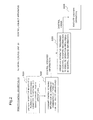
- Fig. 2 is a sequence diagram showing operation according to the basic exemplary embodiment of the present invention.
- the remote control apparatus 10 captures respective images of a plurality of optional apparatuses connected to the network, and thereby identifies control-object apparatuses (S201).
- the remote control apparatus 10 transmits control scenario information determined by a combination of types of the control-object apparatuses (S202).
- the control scenario information is sent to the network control unit 20.
- the network control unit 20 outputs control orders to execute operations prescribed by the control scenario information to apparatuses prescribed by the control scenario information (S203).
- the control orders are each sent to respective control-object apparatuses.
- Each of control-object apparatuses having received the control orders executes operations specified by the respective control orders (S204).
- Fig. 3 is a block configuration diagram showing a configuration of the remote control apparatus according to the basic exemplary embodiment of the present invention.
- the remote control apparatus 10 is a remote control apparatus to remotely control a plurality of apparatuses contained by the network control unit.
- the remote control apparatus 10 comprises a control-object apparatus identification means 11 which captures respective images of a plurality of apparatuses and thereby identifies apparatuses to control.
- the remote control apparatus 10 further comprises a control scenario output means 12 which outputs control scenario information prescribing operations of each apparatus in cooperative operation between a plurality of control-object apparatuses, which is determined by a combination of types of the identified control-object apparatuses. Then, the aforementioned network control unit receives the control scenario information, and causes the control-object apparatuses to execute operations prescribed by the control scenario information.
- the user points the remote control apparatus 10 at apparatuses desired to be control objects of cooperative operation, and captures images of the apparatuses.
- This operation manner is an intuitive behavior style of remote controller operation which has been familiar to users.
- a combination of types of control-object apparatuses identified by the operation determines control scenario information concerning cooperative operation among a plurality of control-object apparatuses. As the control scenario information prescribes apparatuses to be controlled and their operations, each control-object apparatus can execute cooperative control operations on the basis of the control scenario information.
- Fig. 4 is a block configuration diagram showing a configuration of the remote control apparatus according to the exemplary embodiment 1 of the present invention.
- the user captures images of apparatuses desired to be control objects of cooperative operation by pointing a remote control apparatus 10 at the apparatuses.
- the user captures respective images of a television and a DVD player.
- the images of the apparatuses obtained by this operation are transmitted to a control-object apparatus identification means 11.
- the control-object apparatus identification means 11 identifies control-object apparatuses by comparing the inputted images of the apparatuses with images for comparison 112 stored in advance, using an image comparison means 111.
- the information on the identified control-object apparatuses is transmitted to a control scenario output means 12.
- the control scenario output means 12 searches, on the basis of a combination of types of the identified control apparatuses and using a control scenario search means 121, to find which control scenario of control scenario registration information stored in advance in a control scenario registration information storage means 122 corresponds to the combination.
- control scenario While a control scenario will be described later, it is assumed here that performing the following control operations is prescribed as a control scenario for the case where respective images of a television and a DVD player are captured, for example.
- this is an example of a control scenario which orders to connect a DVD player to a television, turn on the television and the DVD player and prepare for watching video images played by the DVD player on the television.
- the information retrieved from the control scenario registration information storage means 122 includes a control scenario such as that described above corresponding to the combination of a television and a DVD player, or control scenario identification information enabling to identify a scenario having the above-described contents.
- the control scenario output means 12 outputs the control scenario information obtained by the search via a communication means 123.
- control scenario information outputted from the remote control apparatus 10 includes either a control scenario itself prescribing specific operations of each apparatus or control scenario identification information enabling to identify a control scenario having such contents.
- an indicator flag for indicating which type of control scenario information is outputted may be attached.
- Fig. 5 is a block configuration diagram showing a configuration of the network control unit according to the exemplary embodiment 1 of the present invention.
- the control scenario information outputted by the remote control apparatus 10 is received by a communication means 21 of the network control unit 20, and is transmitted to a control scenario analysis means 22.
- control scenario analysis means 22 searches a control scenario registration information storage means 25 by the control scenario identification information. By the search, the control scenario analysis means 22 acquires information on specific operation contents with respect to each apparatus which are prescribed by a corresponding control scenario.
- control scenario information outputted by the remote control apparatus 10 is a control scenario itself prescribing specific operations of each apparatus, the above-described searching operation is not necessary.
- control scenario analysis means 22 can identify, by the indicator flag, the one to perform between the two kinds of operations described above. Further, even when an indicator flag is not attached, the control scenario analysis means 22 can identify which of the two kinds of control scenario information is received, by observing the data amount of the received control scenario information.
- control scenario analysis means 22 On acquiring control-object apparatuses and contents of specific operations prescribed by the control scenario, the control scenario analysis means 22 analyzes them. By the analysis, the control scenario analysis means 22 identifies each control-object apparatus and prepares for generating control order data for each control-object apparatus. Specifically, it outputs control order data including control-object apparatus information specifying each control-object apparatus and the type of a control order generated for each control-object apparatus. Additionally, information on connections between the control-object apparatuses may be included.
- the control scenario analysis means 22 transmits the analysis result data to a control order data generation means 23 and directs it to generate control order data.
- control order data generation means 23 On receiving the direction to generate control order data for each control-object apparatus from the control scenario analysis means 22, the control order data generation means 23 generates control order data corresponding to each control-object apparatus on the basis of the transmitted analysis result data. Then, the control order data generation means 23 transmits the generated control order data to an apparatus connection means 24.
- the apparatus connection means 24 is equipped with ports to connect respective apparatuses, and can identify which of the ports each control-object apparatus is connected to.
- connection control is ordered to the connection means 24.
- connection means 24 For example, when control of "connect video and audio outputs of a DVD player to a line input of a television" can be executed by the apparatus connection means 24, the connection control is ordered to the apparatus connection means 24.
- the apparatus connection means 24 sends control order data to a corresponding control-object apparatus. For example, it sends control order data of "power on” and “switch input source to line input” to a television, and that of "power on” to a DVD player.
- each of the control-object apparatuses can execute the cooperative operation. That is, by only the user's capturing images of a television and a DVD player, the image comparison means 111 compares inputted images of the apparatuses with images for comparison 112 stored in advance, and thereby identifies control-object apparatuses as the television and the DVD player.
- control-object apparatuses are the television and the DVD player
- the control scenario search means 121 searches the control scenario registration information storage means 122 to find which one of control scenarios stored in advance in the registration information storage means 122 corresponds to the combination of control-object apparatuses. Then, the retrieved control scenario is sent to the network control unit 20, where specific contents of the control scenario are analyzed by the control scenario analysis means 22. As a result of the analysis, pieces of control order data prescribing operations of respective apparatuses are generated by the control order data generation means 23, and the pieces of control order data are sent to respective apparatuses. Consequently, the DVD player is connected to the television, and the television and the DVD player are turned on, and thereby preparation for watching video images played by the DVD player on the television is accomplished.
- Fig. 6 is a block diagram showing a system configuration according to the exemplary embodiment 2 of the present invention.
- the exemplary embodiment 2 is an example of applying the present invention to an internal network established by wireless LAN (Local Area Network), power line communication network or the like.
- wireless LAN Local Area Network
- power line communication network or the like.
- a network control unit 20 is equipped with a control apparatus establishing such an internal network, and communicates with a remote control apparatus 10 by wireless.
- a wireless communication method in this case, wireless LAN, Bluetooth (registered trademark) or low power wireless communication may be applied. Accordingly, even when the distance between the remote control apparatus 10 and the network control unit 20 is from at least 10 to 100 meters, communication is possible between the two. Therefore, the use of the present exemplary embodiment is not limited to that in a home, but is possible also in a meeting room, a small hall, an event site or the like.
- the network control unit 20 can contain a plurality of apparatuses. In Fig. 6 , three contained apparatuses are illustrated as examples.
- the network control unit 20 is supposed to contain a control-object apparatus A, 30, and a control-object apparatus B, 40, which are intended to be objects of remote control by the user, and an apparatus C, 50, which is not intended to be an object of remote control at present.
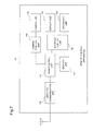
- Fig. 7 is a block configuration diagram showing a configuration of the remote control apparatus 10 according to the exemplary embodiment 2 of the present invention.
- the remote control apparatus 10 is equipped, at the outside surface of its body, with a camera unit 102 for capturing an image of an apparatus to be a control object, an operation unit 104 for performing input operations of remote control and a display unit 103 for presenting operation methods of the operation unit 104 and the like.
- main control unit 101 Within the body, included are a main control unit 101, a camera control unit 105, an interface control unit 106, a memory unit 107 and a wireless communication unit 108, as primary components.
- the main control unit 101 is in charge of control relevant to overall operation of the remote control apparatus 10 by the use of a main program stored in the memory unit 107. Besides the main program, various application programs are stored in the memory unit 107. The application programs stored in the memory unit 107 execute control operations of the remote control apparatus 10 in cooperation with the main control unit 101 and other control units such as the camera control unit 105 and the interface control unit 106.
- the image comparison means and the control scenario search means described with respect to the exemplary embodiment 1 are achieved by control operations executed by the main control unit 101.
- the memory unit 107 is provided with areas for storing image information for comparison and control scenario registration information described above with respect to the exemplary embodiment 1.
- a control interface program for each control-object apparatus which will be described later, is stored in the memory unit 107.
- the camera control unit 105 executes control relevant to an image-capturing operation using the camera unit 102.
- the interface control unit 106 performs control such as of displaying on the display unit 103 and of identifying information inputted by operations on the operation unit 104.
- the wireless communication unit 108 performs wireless communication between the remote control apparatus 10 and the network control unit 20.
- Fig. 8 is a block configuration diagram showing an example of a configuration of the network control unit 20 according to the exemplary embodiment 2 of the present invention.
- a control unit 201 is in charge of control relevant to overall operation of the network control unit 20 by the use of a program stored in a memory unit 204.
- the control scenario analysis means and the control order data generation means described with respect to the exemplary embodiment 1 are achieved by control operations executed by the control unit 201.
- the memory unit 204 is provided with areas for storing, besides the program, the control scenario registration information described above with respect to the exemplary embodiment 1 and various kinds of data relevant to the contained apparatuses.
- a connection unit 205 is equipped with apparatus connection ports 206 for connecting the contained apparatuses, and executes control for which setting of connections between the apparatuses is possible within the network control unit.
- a routing unit 202 performs routing of control order data, which is outputted from the control unit 201 and to be transmitted to control-object apparatuses, to objective ports of the connection unit 205.
- a wireless communication unit 203 performs wireless communication between the network control unit 20 and the remote control apparatus 10.
- Fig. 10 is a diagram showing an example of an initial menu screen displayed on the display unit 103 of the remote control apparatus 10 according to the exemplary embodiment 2 of the present invention.
- the remote control apparatus 10 has three operation modes.
- a registration mode is an operation mode for registering apparatuses intended to be objects of remote control in advance.
- a solitary control mode is an operation mode for remotely controlling apparatuses individually.
- a linked control mode is an operation mode for remotely controlling a plurality of apparatuses in a cooperative manner.
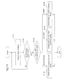
- Fig. 11 is a flow diagram showing initial menu operation of the remote control apparatus 10.
- the initial menu screen shown in Fig. 10 appears on the display unit 103 of the remote control apparatus 10, and the remote control apparatus 10 enters a state of waiting for an input of control by the user (S1101, NO at S1102)
- operation of the registration mode is executed (S1104).
- operation of the solitary control mode is executed (S1105).
- operation of the linked control mode is executed (S1106).
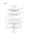
- Fig. 12 is a flow diagram showing operation of control-object apparatus registration in the remote control apparatus 10.
- the control unit 201 of the network control unit 20 recognizes the apparatuses by communication with a control unit of each apparatus, which is not illustrated in the drawings. Then, type information and connection position information on the connected apparatuses are identified. Further, an address for the use in the internal network is given to each apparatus by, for example, a DHCP (Dynamic Host Configuration Protocol) function. Then, in the memory unit 204 of the network control unit 20, those pieces of information on each apparatus connected to the network control unit 20 are stored as connected device information.
- DHCP Dynamic Host Configuration Protocol
- the remote control apparatus 10 When the remote control apparatus 10 starts operation of the registration mode in this state, the remote control apparatus 10 communicates with the network control unit 20 and thereby acquires the connected device information from the network control unit 20 (S1201).
- Fig. 13 shows a situation where apparatus types, port numbers and addresses of apparatuses connected to the network control unit 20 are displayed.
- the user selects an apparatus desired to be registered as a control-object apparatus and performs a determination operation (S1203).
- This user operation is transmitted from the operation unit 104 of the remote control apparatus 10 to the main control unit 101 via the interface control unit 106.
- the main control unit 101 orders the camera control unit 105 to start up the camera unit 102.
- the user Using the activated camera unit 102, the user captures an image of an exterior view of the control-object apparatus, and performs a registration operation (S1204).
- the user may capture images of a plurality of exterior views from different angles.
- a sign indicating completion of registration is given on the display unit 103, and its image is stored in the memory unit 107 of the remote control apparatus 10 as an image for comparison, being related to relevant apparatus information including an apparatus type, a port number, an address and the like.
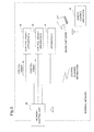
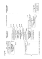
- Fig. 14 is a sequence diagram showing operation relevant to the solitary control mode.
- the user selects the solitary control mode on the initial menu screen on the display unit 103 of the remote control apparatus 10 and performs a determination operation (S1401).
- This user operation is transmitted from the operation unit 104 to the main control unit 101 via the interface control unit 106, of the remote control apparatus 10.
- the main control unit 101 orders the camera control unit 105 to start up the camera unit 102.
- the user performs an image capturing operation with the activated camera unit 102 pointed at a control-object apparatus (S1402) . That is, if the display unit 103 has been switched to show a monitor screen, the user may release the shutter after confirming the control-object apparatus is displayed on the monitor screen.
- a control-object apparatus S1402
- the image captured by the user is sent from the camera control unit 105 to the main control unit 101 (S1403), and is compared with images for comparison registered in the registration mode (S1404).
- retrieved is apparatus information stored in relation to an image for comparison which matches the presently captured image, and thereby the control-object apparatus is identified (S1405).
- the main control unit 101 retrieves an interface program corresponding to the apparatus from the memory unit 107, and transmits it to the interface control unit 106.
- the interface control unit 106 defines keys of the operation unit 104 as that in an operation-key arrangement according to the transferred interface program, and displays their descriptions on the display unit 103 (S1407).
- Fig. 15 is a diagram showing examples of operation-key description screens in the solitary control mode displayed on the display unit 103 of the remote control apparatus 10.
- Fig. 15(a) is presented when the control-object apparatus is identified as a television. Shown is an example where a four-way directional key is used for volume control and channel switching, numeric keys for direct input of channel numbers, and a determination key for power-on and off.
- Fig. 15(b) is presented when the control-object apparatus is identified as an audio apparatus. Shown is an example where the four-way directional key is used for volume control and changing a title to play, the numeric keys for directly specifying a title to play, and the determination key for power-on and off.
- Fig. 15(c) is presented when the control-object apparatus is identified as a lighting apparatus. Shown is an example where the four-way directional key is used for brightness control, and the determination key for power-on and off. It would not be necessary to mention that these figures are shown just as examples, and the settings are not limited to them.
- the user performs desired remote control by operating the keys of the operation unit 104 of the remote control apparatus 10 (S1408).
- This user operation is transmitted from the operation unit 104 of the remote control apparatus 10 to the main control unit 101 via the interface control unit 106.
- the main control unit 101 identifies control content of the user operation, and generates control order data according to the content, and transmits it to the network control unit 20 via the wireless communication unit 108 (S1409).
- the control order data transmitted to the network control unit 20 includes address information specifying the control-object apparatus. Further, in order to discriminate from the linked control mode, which will be described later, a control mode flag indicating the solitary control mode is attached.
- the control order data is received by the wireless communication unit 206 of the network control unit 20, and is transmitted to the control unit 201.
- control unit 201 of the network control unit 20 identifies that the solitary control mode is in operation. Further, the control unit 201 identifies the control-object apparatus from the address information included in the control order data (S1410).
- control unit 201 transmits the control order data to the control-object apparatus via the routing unit 202 and via the connection unit 205 (S1411).
- the control-object apparatus executes operations specified by the received control order data (S1412).
- an apparatus whose image is captured by the user pointing the camera unit 102 of the remote control apparatus 10 at the apparatus is identified as an object apparatus of the remote control, and control according to a type of the apparatus can be performed. Further, if the camera unit 102 is provided with a zoom function, because an object apparatus can be captured in an image from a distance, the uses in a large meeting room, a small hall, an event site and the like are possible.
- the following configuration may be employed in consideration of the use at a place such as where apparatuses to control are densely installed.
- a configuration of the remote control apparatus 10 may be such that, from among images displayed on the display unit 103 when the user points the camera unit 102 at a control-object apparatus, a square frame, for example, is superposed on an image which the camera unit 102 recognizes as a capturing target.
- the remote control apparatus 10 may be configured to send a control signal indicating an identified control-object apparatus to the network control unit 20 when the apparatus is identified by an acquired image in the step S1405 in Fug. 5.
- the network control unit 20 transmits control order data to order to light up a display means installed in the object apparatus.
- An LED Light Emitting Diode
- the linked control mode is an operation mode capable of causing a plurality of control-object apparatuses to perform operations in a linked manner.
- Operations of the linked control mode include operation for registering a control scenario and linked control mode execution operation for remotely controlling a plurality of apparatuses in a linked manner under a situation where a control scenario has been registered.
- Fig. 16 is a sequence diagram showing operation relevant to control scenario registration in the linked control mode of the exemplary embodiment 2 according to the present invention.
- a screen on the display unit 103 switches to a menu screen of the linked control mode shown in Fig. 17(a) .
- this menu screen of the linked control mode selection between a control scenario registration operation and a linked control mode execution operation is possible.
- the user selects "DVD player" from the screen of registered apparatuses list and performs its setting (S1602).
- an operation registration screen according to the selected apparatus type, for selecting among operation contents possible to be set.
- the user selects an operation of "video output” and performs its setting (S1603).
- the user sets and registers the operation desired to be performed next. In the present case, the user selects and sets "sound output", and then does "power on”.
- the registered control scenario is stored in the memory unit 107 of the remote control apparatus 10, and the same control scenario is transmitted to the network control unit 20 (S1606).
- Control scenarios are created by the above-described operations, and are held by both the remote control apparatus 10 and the network control unit 20.
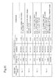
- Fig. 20 is a diagram showing examples of control scenarios of the linked control mode of the exemplary embodiment 2 according to the present invention. Given a scenario identification number, each control scenario is stored in each of the memory unit 107 of the remote control apparatus 10 and the memory unit 204 of the network control unit 20.
- control scenarios shown in Fig. 20 prescribe the following cooperative operations respectively.
- a scenario identification number No.1 prescribes "output sound of TV from audio apparatus”.
- a scenario identification number No.2 prescribes "output video and sound played by DVD player from TV”.
- a scenario identification number No.3 prescribes "output video and sound played by DVD player from TV and audio apparatus, respectively”.
- a scenario identification number No.4 prescribes "output video and sound played by DVD player from TV and audio apparatus, respectively, and set brightness of lighting apparatus at theater mode”.
- the registration method of a control scenario described above is just an example, and the method is not limited to it.
- the method may be configured such that scenarios of different control contents can be registered according to a selection order of control-object apparatuses.
- registered may be a control scenario where a selection of "TV” prescribes operation of "video recording” and a subsequent selection of ""DVD” prescribes operations for TV program recording.
- remote control operations to be performed by the user are selecting "DVD” and subsequently selecting "TV” .
- the user selects "TV” and subsequently selects "DVD”.
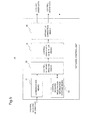
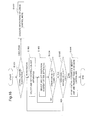
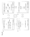
- Fig. 18 is a sequence diagram showing operation according to remote control of the linked control mode.
- this user operation is transmitted from the operation unit 104 of the remote control apparatus 10 to the main control unit 101 via the interface control unit 106. Receiving the transmission of the user operation, the main control unit 101 orders the camera control unit 105 to start up the camera unit 102.
- the user performs an operation of capturing an image of a control-object apparatus with the camera unit 102 pointed at the apparatus, on each of a plurality of control-object apparatuses (S1802). That is, to perform a linked control of "output video and sound played by DVD player from TV", the user needs only to capture an image of "DVD player" and subsequently of "TV".
- the images captured by the user are sent one by one from the camera control unit 105 to the main control unit 101 (S1803), and are compared with images for comparison registered in the registration mode (S1804).
- retrieved are pieces of apparatus information each stored in relation to respective images for comparison matching the captured images, and thereby the control-object apparatuses are identified (S1805). In this case, "DVD player" and "TV” are identified.
- the main control unit 101 searches for a control scenario determined by the combination of the identified control-object apparatuses from among registered control scenarios stored in the memory unit 107 (S1806). For example, from the control scenarios list shown in Fig. 20 , the scenario identification number No.2 is retrieved.
- the main control unit 101 transmits control scenario information to the network control unit 20 so as to cause it to execute operations based on the control scenario.
- the control scenario information transmitted from the remote control apparatus 10 to the network control unit 20 may be content itself of the control scenario and also may be identification information for enabling identification of the content of the control scenario. In the present case, it is assumed that a scenario identification number is transmitted, in order to reduce transmitted information amount.
- the main control unit 101 generates control order data including a control mode flag indicating the linked control mode and the scenario identification number (No.2), and transmits it to the network control unit 20 via the wireless communication unit 108 (S1807).
- the control order data received by the wireless communication unit 203 of the network control unit 20 is transmitted to the control unit 201.
- the control unit 201 searches the control scenarios stored in the memory unit 204 and retrieves a corresponding control scenario (S1808).
- DVD player and TV are identified as control-object apparatuses, along with their respective addresses and port numbers. Then, as operations to be executed, identified are "output video and sound of DVD player to TV”, “power on of DVD player”, “power on of TV” and "switch input source of TV”.
- the control unit 201 executes operations, from among the identified operations, which are possible in the network control unit 20 such as connection settings between the apparatuses. (S1809). For example, when the operation of "output video and sound of DVD player to TV" can be executed by controlling the connection unit 205, the control unit 201 orders the connection unit 205 to execute a corresponding connection.
- control unit 201 generates pieces of control order data to be transmitted to the respective control-object apparatuses and transmits them, via the routing unit 202 and the connection unit 205, from the ports to which the respective apparatuses are connected (S1810).
- Each of the pieces of control order data includes commands indicating operations to execute, and address and port information for routing. Through these pieces of control order data, information on the operations to execute is transmitted to the objective apparatuses.
- control order data including a command of "power on” is transmitted to "DVD player".
- Each apparatus executes operations according to the commands included in the received control order data (S1811).
- the remote control apparatus 10 sets the operation unit 104 into a state where the user can input the next control of the linked control.
- the main control unit 101 retrieves interface programs corresponding to the control-object apparatuses identified at S1805 from the memory unit 107 (S1812) and transmits them to the interface control unit 106.
- interface programs of "DVD player" and "TV” are retrieved.
- the interface control unit 106 defines the keys of the operation unit 104 as that in an operation key arrangement according to the transmitted interface programs, and presents their descriptions on the display unit 103 (S1813). While, in the linked control mode, interface programs relevant to a plurality of apparatuses are retrieved, only one of the interfaces is displayed on the display unit 103 , but a user operation can switch an interface to be displayed.
- Fig. 19 is a diagram showing examples of screens in the linked control mode displayed on the display unit 103 of the remote control apparatus 10.
- Fig. 19 shows a situation where four interface programs respectively of "DVD player”, “audio apparatus”, “TV” and “lighting apparatus” are retrieved and switched as necessary.
- the user performs desired remote control by operating the keys of the operation unit 104 of the remote control apparatus 10 (S1814). For example, in the situation where, by the linked control described above, the DVD player and the television are connected with each other and are in the power-on state, it is assumed that the operation unit 104 is set as an operation interface of "DVD player".
- the user may perform an operation corresponding to "play".
- This user operation is transmitted from the operation unit 104 of the remote control apparatus 10 to the main control unit 101 via the interface control unit 106.
- the main control unit 101 identifies the control content operated by the user.
- the main control unit 101 generates control order data of the identified control content, and transmits it to the network control unit 20 via the wireless communication unit 108 (S1815).
- the control order data transmitted to the network control unit 20 includes address information identifying a control-object apparatus. Additionally, a control mode flag indicating the linked control mode is attached.
- This control order data is received by the wireless communication unit 203 of the network control unit 20, and is transmitted to the control unit 201.
- control unit 201 of the network control unit 20 identifies that the present control is in the linked control mode. Further, the control unit 201 identifies a control-object apparatus by address information included in the control order data (S1816).
- control unit 201 transmits the control order data, via the routing unit 202 and the connection unit 205, to the apparatus to be controlled (S1817).
- the control-object apparatus executes an operation designated in the received control order data (S1818).
- scenarios of linked control among a plurality of apparatuses can be set. Then, identified are a plurality of apparatuses whose images are captured by the user pointing the camera unit 102 of the remote control apparatus 10 at the apparatuses, as object apparatuses of the remote control, and linked control according to the combination of the apparatuses can be performed. Further, if the camera unit 102 is provided with a zoom function, object apparatuses can be captured in images from a distance. Accordingly, such linked control between apparatuses can be used also in a large meeting room, a small hall, an event site or the like.
- a configuration of the remote control apparatus 10 may be such that, from among images displayed on the display unit 103 when the user points the camera unit 102 at a control-object apparatus, a square frame, for example, is superposed on an image which the camera unit 102 recognizes as a capturing target.
- the step S1805 in Fig. 18 may include a step of lighting up a display means, including an LED, of an apparatus, on identifying the apparatus as a control-object apparatus by its acquired image.
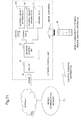
- Fig. 21 is a block diagram showing a system configuration according to the exemplary embodiment 3 of the present invention.
- a remote control apparatus 60 is in the form of being installed in a mobile communication terminal such as a mobile phone.
- a network control unit 70 of the exemplary embodiment 3 does not need to communicate directly with the remote control apparatus 60, and communication between them is performed at least via a mobile communication network.
- Fig. 22 is a block diagram showing an example of a configuration of the network control unit according to the exemplary embodiment 3 of the present invention.
- the network control unit 70 has a configuration which is obtained by removing the wireless communication unit 203 from the network control unit 20 of the exemplary embodiment 2 shown in Fig. 8 . Then, its communication with the remote control apparatus 60 is performed via a mobile communication network and the internet with an intervention of a router 80 constituting a local area network. Accordingly, as shown in Fig. 22 , the network control unit 70 is equipped with a communication unit 703 capable of communicating with the router 80.
- a configuration of the remote control apparatus 60 may be such that, from among images displayed on the display unit 103 when the user points the camera unit 102 at a control-object apparatus, a square frame, for example, is superposed on an image which the camera unit 102 recognizes as a capturing target. Further, it may be determined to light up a display means, including an LED, of an apparatus identified by a captured image.
- the present exemplary embodiment 3 enables to use mobile phone communication for transmitting control information, and enables also to identify an apparatus installed in the distance when using a zoom function of the camera unit, and therefore, it fits the use at a widely opened place such as a temporary outdoor event site and a theme park.
Landscapes
- Engineering & Computer Science (AREA)
- Computer Networks & Wireless Communication (AREA)
- Physics & Mathematics (AREA)
- General Physics & Mathematics (AREA)
- Selective Calling Equipment (AREA)
- Telephonic Communication Services (AREA)
- Telephone Function (AREA)
Abstract
Description
- The present invention relates to a remote control system, a remote control apparatus and a remote control method, and in particular to a remote control system, a remote control apparatus and a remote control method for apparatuses connected to a network.
- An infrared remote controller is widely used now as a remote control apparatus to control, a machine or an electronic apparatus from a distance. It performs desired control remotely on a machine or an electronic apparatus, by transmitting infrared beams modulated by control data toward an infrared receiving unit of the machine or electronic apparatus. When an infrared remote controller is used, controllable range is limited to a range within less than about ±5 degrees in upper, lower, left and right directions from the direct front, which is determined by the spreading extent of infrared beams, and within a distance of about 5 to 10 meters, which is determined by the reaching distance of infrared beams.
- Such an infrared remote controller is attached to every kind of apparatus because of its operation convenience. For example, it is provided to customers by being attached to a television, DVD (Digital Versatile Disk) recorder/player, audio system, air conditioner, lighting apparatus, camera, game machine, personal computer and the like. Further, as an apparatus provided for the purpose of integrating infrared remote controllers attached to so many apparatuses into a single controller, there are apparatuses called a learning remote controller and a multi remote controller.
- In recent years, not only communication-related apparatuses but also many other kinds of apparatuses such as AV (Audio Visual) and control apparatuses have come to be connected to a network. For example, with a home network being built in a home, and AV apparatuses such as a television, a DVD recorder/player, and an audio system, or control apparatuses such as an air conditioner, a lighting apparatus and a security system being connected to the home network, these apparatuses can be controlled from outside the home.
-
Patent document 1 discloses a technology of a remote control apparatus which remotely controls an apparatus via a network by capturing images of apparatuses connected to the network, and, when controlling an apparatus, displaying the captured image on a display unit and selecting the desired apparatus. Further, the remote control apparatus can remotely control a plurality of different kinds of apparatuses by itself alone. - When capturing an image of an apparatus to be an object of remote control, the remote control apparatus disclosed in
patent document 1 acquires apparatus-specific information in the form of infrared signals from the apparatus itself, and stores it in a memory relating it to the captured image. During remote control, when a user selects a desired apparatus from images displayed on the display unit, a user interface, an operation control program and apparatus-specific information corresponding to the selected image are retrieved. Then, a user interface for controlling the apparatus to be an object of the remote control is displayed on the display unit, and the remote control apparatus makes a connection to the apparatus connected to the network, using a wireless communication means and on the basis of the apparatus-specific information. Subsequently, the user can remotely control the apparatus connected to the network by performing operations based on the user interface displayed on the display unit of the remote control apparatus. -
Patent document 2 discloses a technology of a control system for remote control which a user wears on his/her head and which is equipped with an image-capturing device for capturing an image of an area within his/her sight. This control system also can remotely control a plurality of different kinds of apparatuses by itself alone. - The control system disclosed in
patent document 2 recognizes a control-object apparatus on the basis of image information obtained by the image-capturing device, triggered by the control-object apparatus's entering the user's sight, and of identification information stored in a storage device, and sends an operation command inputted by the user to the control-object apparatus. Accordingly, this control system can automatically identify a control-object apparatus entering the usher's sight and then remotely control the control-object apparatus. Further, the user inputs an operating command by pointing on a virtual controller displayed on a semi-transparent type optical element which is provided in the control system he/she wears. -
Patent document 3 discloses a technology of a remote control apparatus which makes possible remote control of a plurality of objective apparatuses without adding any function to the control-object apparatuses. - The remote control apparatus disclosed in
patent document 3 captures an image of a control-object apparatus, extracts a letter string from the captured image, and thereby identifies the control-object apparatus from among a plurality of objective apparatuses. Then, the remote control apparatus sets each button of an operation unit according to the specified control-object apparatus, and displays an operation method of the operation unit on a liquid crystal display unit. Here, the remote control apparatus uses conventional infrared beams in the remote control of the identified apparatus. Accordingly, in the technology disclosed inpatent document 3, an artifice such as of providing a remote control apparatus for relaying is made in order to expand the controllable range. -
- [Patent Document 1] Japanese Patent Application Laid-Open No.
2007-259328 - [Patent Document 2] Japanese Patent Application Laid-Open No.
2006-146803 - [Patent Document 3] Japanese Patent Application Laid-Open No.
2005-268941 - Remote control operation by an infrared remote controller is very intuitive operation of pressing an operation button with the remote controller pointed at an apparatus to control. However, as described above, when an infrared remote controller is used, controllable range is limited to a range within less than about ±5 degrees in upper, lower, left and right directions from the direct front, which is determined by the spreading extent of infrared beams, and within a distance range of about 5 to 10 meters, which is determined by the reaching distance of infrared beams. Further, although there are apparatuses capable of integrating a plurality of infrared remote controls into a single one, such as a learning remote controller and a multi remote controller, it is difficult for them to perform control of a plurality of apparatuses in a linked manner. For example, they cannot perform linked control between apparatuses such as of, for the purpose of watching a movie recorded in a DVD, turning on a television and a DVD player and causing the DVD player to play the DVD.
- The remote control apparatus disclosed in
patent document 1 can perform remote control without depending on the distance from a control-object apparatus. However, even when a control-object apparatus exists in a short distance, the remote control apparatus requires operations of extracting images stored in a memory and selecting a specific image while watching the images displayed on a liquid crystal screen of the remote control apparatus. Therefore, with this remote control apparatus, it is impossible to perform an intuitive operation of operating the remote control apparatus while pointing it at an apparatus to control, which have been familiar to users for many years. - Even when a non-directional remote controller comes to be used, it is considered to be desired not to break the familiar behavior style of remote control operation of operating a remote controller while pointing it at an apparatus to control.
- The control system disclosed in
patent document 2 has a characteristic in that it identifies a control-object apparatus by a captured image. However, the user is required to perform a peculiar operation such as of inputting an operation command by pointing on a virtual controller displayed on a semi-transparent optical element. Further, accordingly, the system configuration is complicated. - Although the remote control apparatus disclosed in
patent document 3 has a characteristic in that it extracts a letter string from a captured image when identifying a control-object apparatus, it performs conventional remote control using infrared beams. Accordingly, even though a disclosure of a remote control apparatus for relaying is also given there, the configuration becomes complicated and the controllable range is limited. - The technologies disclosed in
patent documents 1 to 3 each can provide a remote control apparatus capable of remotely controlling a plurality of different kinds of apparatuses by itself alone. However, it is difficult for the technologies disclosed inpatent documents 1 to 3 to provide a remote control apparatus capable of performing remote control of a plurality of different kinds of apparatuses in a linked manner. - The objective of the present invention is to provide a remote control system, a remote control apparatus and a remote control method which solve the above-described problem.
- In order to achieve the objective described above, a remote control system in the present invention comprises: a remote control apparatus which captures respective images of a plurality of apparatuses connected to a network, thereby identifies control-object apparatuses, and transmits control scenario information concerning cooperative operation among a plurality of control-object apparatuses, which is determined by a combination of types of the identified control-object apparatuses; and a network control unit which constitutes the network containing the aforementioned plurality of apparatuses, and, when receiving the control scenario information from the remote control apparatus, outputs, to apparatuses prescribed by the received control scenario information, control orders to cause the apparatuses to perform operations prescribed by the received control scenario information.
- Further, a remote control apparatus of the present invention is a remote control apparatus remotely controlling a plurality of apparatuses contained in a network control unit, and is characterized by that it comprises: a control-object apparatus identification means for capturing respective images of a plurality of aforementioned apparatuses and thereby identifying apparatuses to control; and a control scenario output means for outputting control scenario information which prescribes operations of each of the control-object apparatuses in cooperative operation among a plurality of control-object apparatuses, which is determined by a combination of types of the identified control-object apparatuses, and also in that the network control unit receives the control scenario information and causes the control-object apparatuses to execute operations prescribed by the control scenario information.
- Further, a remote control method of the present invention is characterized by that it comprises: a control-object apparatus identification step wherein a remote control apparatus captures respective image of a plurality of apparatuses connected to a network control unit, and thereby identifies control-object apparatuses; a control scenario transmission step wherein the remote control apparatus transmits control scenario information concerning cooperative operation between a plurality of control-object apparatuses, which is determined by a combination of types of the identified control-object apparatuses; and a control order output step wherein the network control unit outputs, to apparatuses prescribed by the received control scenario information, control orders to cause the apparatuses to perform operations prescribed by the received control scenario information.
- According to the present invention, it is possible to perform remote control of a plurality of different kinds of apparatuses in a linked manner, without breaking an intuitive behavior style of remote control operation which has been familiar to users.
-
- [
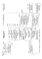
Fig.1] Fig.1 is a block configuration diagram showing a system configuration according to a basic exemplary embodiment of the present invention. - [
Fig.2] Fig.2 is a sequence diagram showing operation according to the basic exemplary embodiment of the present invention. - [
Fig.3] Fig.3 is a block configuration diagram showing a configuration of a remote control apparatus according to the basic exemplary embodiment of the present invention. - [
Fig.4] Fig.4 is a block configuration diagram showing a configuration of a remote control apparatus according to anexemplary embodiment 1 of the present invention. - [
Fig.5] Fig.5 is a block configuration diagram showing a configuration of a network control unit according to theexemplary embodiment 1 of the present invention. - [
Fig.6] Fig.6 is a block configuration diagram showing a system configuration according to anexemplary embodiment 2 of the present invention. - [
Fig.7 ] Fag.7 is a block configuration diagram showing a configuration of a remote control apparatus according to theexemplary embodiment 2 of the present invention. - [
Fig.8] Fig.8 is a block configuration diagram showing a configuration of a network control unit according to theexemplary embodiment 2 of the present invention. - [
Fig.9] Fig.9 is an exterior view showing an upper surface appearance of the remote control apparatus according to theexemplary embodiment 2 of the present invention. - [
Fig.10 ] Fin. 10 is a diagram showing an example of an initial menu screen displayed on a display unit of the remote control apparatus according to theexemplary embodiment 2 of the present invention. - [
Fig.11] Fig. 11 is a flow diagram showing operation of an initial menu of the remote control apparatus according to theexemplary embodiment 2 of the present invention. - [
Fig.12] Fig.12 is a flow diagram showing operation of control-object apparatus registration of the remote control apparatus according to theexemplary embodiment 2 of the present invention. - [
Fig.13] Fig.13 is a diagram showing an example of a screen at the time of the operation of control-object apparatus registration displayed on the display unit of the remote control apparatus according to theexemplary embodiment 2 of the present invention. - [
Fig.14] Fig.14 is a sequence diagram showing operation according to a solitary control mode of theexemplary embodiment 2 of the present invention. - [
Fig.15] Fig.15 is a diagram showing examples of screens in the solitary control mode displayed on the display unit of the remote control apparatus according to theexemplary embodiment 2 of the present invention. - [
Fig.16] Fig.16 is a sequence diagram showing operation according to control scenario registration in a linked control mode of theexemplary embodiment 2 of the present invention. - [
Fig.17] Fig.17 is a diagram showing examples of screens, displayed on the display unit, according to the control scenario registration in the linked control mode of theexemplary embodiment 2 of the present invention. - [
Fig.18] Fig.18 is a sequence diagram showing operation according to remote control in the linked control mode of theexemplary embodiment 2 of the present invention. - [
Fig.19] Fig.19 is a diagram showing examples of screens in the linked control mode displayed on the display unit of the remote control apparatus according to theexemplary embodiment 2 of the present invention. - [
Fig.20] Fig.20 is a diagram showing an example of control scenario information in the linked control mode of theexemplary embodiment 2 of the present invention. - [
Fig.21] Fig.21 is a block configuration diagram showing a system configuration according to anexemplary embodiment 3 of the present invention. - [
Fig.22] Fig.22 is a block configuration diagram showing a configuration of a network control unit according to theexemplary embodiment 3 of the present invention. - Exemplary embodiments of the present invention will be described with reference to drawings.
-
Fig. 1 is a block configuration diagram showing a system configuration according to a basic exemplary embodiment of the present invention. - A
remote control apparatus 10 is a device for remotely controlling apparatuses connected to a network. InFig. 1 , apparatuses to be controlled by theremote control apparatus 10 are shown, for example, as a control-object apparatus A, 30, and a control-object apparatus B, 40. While an apparatus C, 50, is also an apparatus connected to the network, it is supposed not to be a control-object apparatus at present. - A
network control unit 20 constitutes the network by containing the control-object apparatus A, 30, control-object apparatus B, 40, and apparatus C, 50. - The
remote control apparatus 10 captures respective images of a plurality of optional apparatuses connected to the network, and thereby identifies apparatuses to be controlled. Theremote control apparatus 10 transmits control scenario information concerning cooperative operation between a plurality of control-object apparatuses which is determined by a combination of types of the identified control-object apparatuses. - When receiving the control scenario information from the
remote control apparatus 10, thenetwork control unit 20 outputs, to apparatuses prescribed by the received control scenario information, control orders to cause the apparatuses to perform operations prescribed by the received control scenario information. -
Fig. 1 schematically illustrates the situation described above, such as where thecontrol apparatus 10 captures respective images of the apparatuses and where it transmits control scenario information. Further,Fig. 1 illustrates also a situation where thenetwork control unit 20 makes orders to apparatuses prescribed by the received control scenario information (control-object apparatus A, 30, and control-object apparatus B, 40) to execute operations prescribed by the control scenario information. -
Fig. 2 is a sequence diagram showing operation according to the basic exemplary embodiment of the present invention. - The
remote control apparatus 10 captures respective images of a plurality of optional apparatuses connected to the network, and thereby identifies control-object apparatuses (S201). Theremote control apparatus 10 transmits control scenario information determined by a combination of types of the control-object apparatuses (S202). The control scenario information is sent to thenetwork control unit 20. Thenetwork control unit 20 outputs control orders to execute operations prescribed by the control scenario information to apparatuses prescribed by the control scenario information (S203). The control orders are each sent to respective control-object apparatuses. Each of control-object apparatuses having received the control orders executes operations specified by the respective control orders (S204). -
Fig. 3 is a block configuration diagram showing a configuration of the remote control apparatus according to the basic exemplary embodiment of the present invention. - The
remote control apparatus 10 is a remote control apparatus to remotely control a plurality of apparatuses contained by the network control unit. Theremote control apparatus 10 comprises a control-object apparatus identification means 11 which captures respective images of a plurality of apparatuses and thereby identifies apparatuses to control. Theremote control apparatus 10 further comprises a control scenario output means 12 which outputs control scenario information prescribing operations of each apparatus in cooperative operation between a plurality of control-object apparatuses, which is determined by a combination of types of the identified control-object apparatuses. Then, the aforementioned network control unit receives the control scenario information, and causes the control-object apparatuses to execute operations prescribed by the control scenario information. - As has been described above, in the basic exemplary embodiment of the present invention, the user points the
remote control apparatus 10 at apparatuses desired to be control objects of cooperative operation, and captures images of the apparatuses. This operation manner is an intuitive behavior style of remote controller operation which has been familiar to users. A combination of types of control-object apparatuses identified by the operation determines control scenario information concerning cooperative operation among a plurality of control-object apparatuses. As the control scenario information prescribes apparatuses to be controlled and their operations, each control-object apparatus can execute cooperative control operations on the basis of the control scenario information. - Next, referring to
Figs. 4 and5 , description will be given of configurations and operation of a remote control apparatus and a network control unit according to anexemplary embodiment 1 of the present invention. -
Fig. 4 is a block configuration diagram showing a configuration of the remote control apparatus according to theexemplary embodiment 1 of the present invention. As described with respect to the basic exemplary embodiment, the user captures images of apparatuses desired to be control objects of cooperative operation by pointing aremote control apparatus 10 at the apparatuses. For example, it is supposed that the user captures respective images of a television and a DVD player. - The images of the apparatuses obtained by this operation are transmitted to a control-object apparatus identification means 11. The control-object apparatus identification means 11 identifies control-object apparatuses by comparing the inputted images of the apparatuses with images for
comparison 112 stored in advance, using an image comparison means 111. The information on the identified control-object apparatuses is transmitted to a control scenario output means 12. - The control scenario output means 12 searches, on the basis of a combination of types of the identified control apparatuses and using a control scenario search means 121, to find which control scenario of control scenario registration information stored in advance in a control scenario registration information storage means 122 corresponds to the combination.
- While a control scenario will be described later, it is assumed here that performing the following control operations is prescribed as a control scenario for the case where respective images of a television and a DVD player are captured, for example.
- * connect video and audio outputs of a DVD player to a line input of a television.
- * turn on the television and the DVD player.
- * switch an input source of the television to the line input.
- That is, this is an example of a control scenario which orders to connect a DVD player to a television, turn on the television and the DVD player and prepare for watching video images played by the DVD player on the television.
- At that time, the information retrieved from the control scenario registration information storage means 122 includes a control scenario such as that described above corresponding to the combination of a television and a DVD player, or control scenario identification information enabling to identify a scenario having the above-described contents.
- The control scenario output means 12 outputs the control scenario information obtained by the search via a communication means 123.
- As described above, the control scenario information outputted from the
remote control apparatus 10 includes either a control scenario itself prescribing specific operations of each apparatus or control scenario identification information enabling to identify a control scenario having such contents. In this case, an indicator flag for indicating which type of control scenario information is outputted may be attached. -
Fig. 5 is a block configuration diagram showing a configuration of the network control unit according to theexemplary embodiment 1 of the present invention. - The control scenario information outputted by the
remote control apparatus 10 is received by a communication means 21 of thenetwork control unit 20, and is transmitted to a control scenario analysis means 22. - When the control scenario information outputted by the
remote control apparatus 10 is control scenario identification information, the control scenario analysis means 22 searches a control scenario registration information storage means 25 by the control scenario identification information. By the search, the control scenario analysis means 22 acquires information on specific operation contents with respect to each apparatus which are prescribed by a corresponding control scenario. - On the other hand, when the control scenario information outputted by the
remote control apparatus 10 is a control scenario itself prescribing specific operations of each apparatus, the above-described searching operation is not necessary. - When the control scenario information is outputted with an indicator flag, the control scenario analysis means 22 can identify, by the indicator flag, the one to perform between the two kinds of operations described above. Further, even when an indicator flag is not attached, the control scenario analysis means 22 can identify which of the two kinds of control scenario information is received, by observing the data amount of the received control scenario information.
- On acquiring control-object apparatuses and contents of specific operations prescribed by the control scenario, the control scenario analysis means 22 analyzes them. By the analysis, the control scenario analysis means 22 identifies each control-object apparatus and prepares for generating control order data for each control-object apparatus. Specifically, it outputs control order data including control-object apparatus information specifying each control-object apparatus and the type of a control order generated for each control-object apparatus. Additionally, information on connections between the control-object apparatuses may be included.
- The control scenario analysis means 22 transmits the analysis result data to a control order data generation means 23 and directs it to generate control order data.
- On receiving the direction to generate control order data for each control-object apparatus from the control scenario analysis means 22, the control order data generation means 23 generates control order data corresponding to each control-object apparatus on the basis of the transmitted analysis result data. Then, the control order data generation means 23 transmits the generated control order data to an apparatus connection means 24.
- The apparatus connection means 24 is equipped with ports to connect respective apparatuses, and can identify which of the ports each control-object apparatus is connected to.
- With respect to a control operation for which setting of connections between apparatuses is possible within the network control unit, the connection control is ordered to the connection means 24. For example, when control of "connect video and audio outputs of a DVD player to a line input of a television" can be executed by the apparatus connection means 24, the connection control is ordered to the apparatus connection means 24.
- Further, with respect to an operation to be executed by individual control-object apparatus, the apparatus connection means 24 sends control order data to a corresponding control-object apparatus. For example, it sends control order data of "power on" and "switch input source to line input" to a television, and that of "power on" to a DVD player.
- In the present exemplary embodiment, resulting from the configurations and operations described above, by only the user's performing remote control operation with the
remote control apparatus 10 pointed at apparatuses desired to be control-object apparatuses of cooperative operation, each of the control-object apparatuses can execute the cooperative operation. That is, by only the user's capturing images of a television and a DVD player, the image comparison means 111 compares inputted images of the apparatuses with images forcomparison 112 stored in advance, and thereby identifies control-object apparatuses as the television and the DVD player. Informed that control-object apparatuses are the television and the DVD player, the control scenario search means 121 searches the control scenario registration information storage means 122 to find which one of control scenarios stored in advance in the registration information storage means 122 corresponds to the combination of control-object apparatuses. Then, the retrieved control scenario is sent to thenetwork control unit 20, where specific contents of the control scenario are analyzed by the control scenario analysis means 22. As a result of the analysis, pieces of control order data prescribing operations of respective apparatuses are generated by the control order data generation means 23, and the pieces of control order data are sent to respective apparatuses. Consequently, the DVD player is connected to the television, and the television and the DVD player are turned on, and thereby preparation for watching video images played by the DVD player on the television is accomplished. - A more detailed exemplary embodiment will be described based on an
exemplary embodiment 2. -
Fig. 6 is a block diagram showing a system configuration according to theexemplary embodiment 2 of the present invention. - The
exemplary embodiment 2 is an example of applying the present invention to an internal network established by wireless LAN (Local Area Network), power line communication network or the like. - A
network control unit 20 is equipped with a control apparatus establishing such an internal network, and communicates with aremote control apparatus 10 by wireless. As a wireless communication method in this case, wireless LAN, Bluetooth (registered trademark) or low power wireless communication may be applied. Accordingly, even when the distance between theremote control apparatus 10 and thenetwork control unit 20 is from at least 10 to 100 meters, communication is possible between the two. Therefore, the use of the present exemplary embodiment is not limited to that in a home, but is possible also in a meeting room, a small hall, an event site or the like. - Other portions of the system configuration are the same as that of the basic exemplary embodiment described above with reference to
Fig. 1 . Thenetwork control unit 20 can contain a plurality of apparatuses. InFig. 6 , three contained apparatuses are illustrated as examples. Thenetwork control unit 20 is supposed to contain a control-object apparatus A, 30, and a control-object apparatus B, 40, which are intended to be objects of remote control by the user, and an apparatus C, 50, which is not intended to be an object of remote control at present. -
Fig. 7 is a block configuration diagram showing a configuration of theremote control apparatus 10 according to theexemplary embodiment 2 of the present invention. - As its exterior is shown in
Fig. 9 , theremote control apparatus 10 is equipped, at the outside surface of its body, with acamera unit 102 for capturing an image of an apparatus to be a control object, anoperation unit 104 for performing input operations of remote control and adisplay unit 103 for presenting operation methods of theoperation unit 104 and the like. - Within the body, included are a
main control unit 101, acamera control unit 105, aninterface control unit 106, amemory unit 107 and awireless communication unit 108, as primary components. - The
main control unit 101 is in charge of control relevant to overall operation of theremote control apparatus 10 by the use of a main program stored in thememory unit 107. Besides the main program, various application programs are stored in thememory unit 107. The application programs stored in thememory unit 107 execute control operations of theremote control apparatus 10 in cooperation with themain control unit 101 and other control units such as thecamera control unit 105 and theinterface control unit 106. Here, the image comparison means and the control scenario search means described with respect to theexemplary embodiment 1 are achieved by control operations executed by themain control unit 101. - Besides those programs, the
memory unit 107 is provided with areas for storing image information for comparison and control scenario registration information described above with respect to theexemplary embodiment 1. In addition, a control interface program for each control-object apparatus, which will be described later, is stored in thememory unit 107. - The
camera control unit 105 executes control relevant to an image-capturing operation using thecamera unit 102. Theinterface control unit 106 performs control such as of displaying on thedisplay unit 103 and of identifying information inputted by operations on theoperation unit 104. - The
wireless communication unit 108 performs wireless communication between theremote control apparatus 10 and thenetwork control unit 20. -
Fig. 8 is a block configuration diagram showing an example of a configuration of thenetwork control unit 20 according to theexemplary embodiment 2 of the present invention. - In
Fig. 8 , acontrol unit 201 is in charge of control relevant to overall operation of thenetwork control unit 20 by the use of a program stored in amemory unit 204. Here, the control scenario analysis means and the control order data generation means described with respect to theexemplary embodiment 1 are achieved by control operations executed by thecontrol unit 201. - The
memory unit 204 is provided with areas for storing, besides the program, the control scenario registration information described above with respect to theexemplary embodiment 1 and various kinds of data relevant to the contained apparatuses. - A
connection unit 205 is equipped withapparatus connection ports 206 for connecting the contained apparatuses, and executes control for which setting of connections between the apparatuses is possible within the network control unit. - A
routing unit 202 performs routing of control order data, which is outputted from thecontrol unit 201 and to be transmitted to control-object apparatuses, to objective ports of theconnection unit 205. - A
wireless communication unit 203 performs wireless communication between thenetwork control unit 20 and theremote control apparatus 10. - Next, operation of the present exemplary embodiment will be described.
-
Fig. 10 is a diagram showing an example of an initial menu screen displayed on thedisplay unit 103 of theremote control apparatus 10 according to theexemplary embodiment 2 of the present invention. - As shown in the initial menu screen, the
remote control apparatus 10 has three operation modes. - A registration mode is an operation mode for registering apparatuses intended to be objects of remote control in advance. A solitary control mode is an operation mode for remotely controlling apparatuses individually. Further, a linked control mode is an operation mode for remotely controlling a plurality of apparatuses in a cooperative manner. By the user's selecting any one of the modes and performing a determination operation with a button for execution, operation of each of the modes is executed.
-
Fig. 11 is a flow diagram showing initial menu operation of theremote control apparatus 10. - In an initial state just after the power is switched on, the initial menu screen shown in
Fig. 10 appears on thedisplay unit 103 of theremote control apparatus 10, and theremote control apparatus 10 enters a state of waiting for an input of control by the user (S1101, NO at S1102) - When the user selects any one of the modes and performs a determination operation with a button for execution (YES at S1102), which one of the menus is selected is identified (S1103).
- When the registration mode is selected, operation of the registration mode is executed (S1104). When the solitary control mode is selected, operation of the solitary control mode is executed (S1105). Further, when the linked control mode is selected, operation of the linked control mode is executed (S1106).
- In the following, operation will be described for each of the modes one by one.
-
Fig. 12 is a flow diagram showing operation of control-object apparatus registration in theremote control apparatus 10. - First, description will be given of information on contained apparatuses, which is managed by the
network control unit 20. - When apparatuses are connected to respective
apparatus connection ports 206 of thenetwork control unit 20, thecontrol unit 201 of thenetwork control unit 20 recognizes the apparatuses by communication with a control unit of each apparatus, which is not illustrated in the drawings. Then, type information and connection position information on the connected apparatuses are identified. Further, an address for the use in the internal network is given to each apparatus by, for example, a DHCP (Dynamic Host Configuration Protocol) function. Then, in thememory unit 204 of thenetwork control unit 20, those pieces of information on each apparatus connected to thenetwork control unit 20 are stored as connected device information. - When the
remote control apparatus 10 starts operation of the registration mode in this state, theremote control apparatus 10 communicates with thenetwork control unit 20 and thereby acquires the connected device information from the network control unit 20 (S1201). - The connected device information acquired from the
network control unit 20 is displayed on thedisplay unit 103 of theremote control apparatus 10, as shown inFig. 13 (S1202).Fig. 13 shows a situation where apparatus types, port numbers and addresses of apparatuses connected to thenetwork control unit 20 are displayed. - The user selects an apparatus desired to be registered as a control-object apparatus and performs a determination operation (S1203). This user operation is transmitted from the
operation unit 104 of theremote control apparatus 10 to themain control unit 101 via theinterface control unit 106. Receiving the transmission of the user operation, themain control unit 101 orders thecamera control unit 105 to start up thecamera unit 102. - Using the activated
camera unit 102, the user captures an image of an exterior view of the control-object apparatus, and performs a registration operation (S1204). In this image capturing of an exterior of the apparatus, the user may capture images of a plurality of exterior views from different angles. By doing such a way, in the cases of the solitary control mode and the linked control mode described later, a comparison operation, which is an operation to identify apparatuses to be control objects, is performed more accurately. - With respect to an apparatus whose registration operation is completed, a sign indicating completion of registration is given on the
display unit 103, and its image is stored in thememory unit 107 of theremote control apparatus 10 as an image for comparison, being related to relevant apparatus information including an apparatus type, a port number, an address and the like. - When the user continues the registration operation (YES at S1205) , operations from the step S1203 described above are repeated again.
- When the user completed the registration operation (NO at S1205), the registration mode operation is ended.
- Next, description will be given of operation of when the user selects the solitary control mode on the initial menu screen, in a situation where the above-described registration mode operation has been completed.
-
Fig. 14 is a sequence diagram showing operation relevant to the solitary control mode. - As a first step, the user selects the solitary control mode on the initial menu screen on the
display unit 103 of theremote control apparatus 10 and performs a determination operation (S1401). This user operation is transmitted from theoperation unit 104 to themain control unit 101 via theinterface control unit 106, of theremote control apparatus 10. Receiving the transmission of the user operation, themain control unit 101 orders thecamera control unit 105 to start up thecamera unit 102. - The user performs an image capturing operation with the activated
camera unit 102 pointed at a control-object apparatus (S1402) . That is, if thedisplay unit 103 has been switched to show a monitor screen, the user may release the shutter after confirming the control-object apparatus is displayed on the monitor screen. - The image captured by the user is sent from the
camera control unit 105 to the main control unit 101 (S1403), and is compared with images for comparison registered in the registration mode (S1404). By this comparison operation, retrieved is apparatus information stored in relation to an image for comparison which matches the presently captured image, and thereby the control-object apparatus is identified (S1405). - When the control-object apparatus is identified, the
main control unit 101 retrieves an interface program corresponding to the apparatus from thememory unit 107, and transmits it to theinterface control unit 106. Theinterface control unit 106 defines keys of theoperation unit 104 as that in an operation-key arrangement according to the transferred interface program, and displays their descriptions on the display unit 103 (S1407). -
Fig. 15 is a diagram showing examples of operation-key description screens in the solitary control mode displayed on thedisplay unit 103 of theremote control apparatus 10. -
Fig. 15(a) is presented when the control-object apparatus is identified as a television. Shown is an example where a four-way directional key is used for volume control and channel switching, numeric keys for direct input of channel numbers, and a determination key for power-on and off.Fig. 15(b) is presented when the control-object apparatus is identified as an audio apparatus. Shown is an example where the four-way directional key is used for volume control and changing a title to play, the numeric keys for directly specifying a title to play, and the determination key for power-on and off. Further,Fig. 15(c) is presented when the control-object apparatus is identified as a lighting apparatus. Shown is an example where the four-way directional key is used for brightness control, and the determination key for power-on and off. It would not be necessary to mention that these figures are shown just as examples, and the settings are not limited to them. - The user performs desired remote control by operating the keys of the
operation unit 104 of the remote control apparatus 10 (S1408). - This user operation is transmitted from the
operation unit 104 of theremote control apparatus 10 to themain control unit 101 via theinterface control unit 106. Themain control unit 101 identifies control content of the user operation, and generates control order data according to the content, and transmits it to thenetwork control unit 20 via the wireless communication unit 108 (S1409). Here, the control order data transmitted to thenetwork control unit 20 includes address information specifying the control-object apparatus. Further, in order to discriminate from the linked control mode, which will be described later, a control mode flag indicating the solitary control mode is attached. - The control order data is received by the
wireless communication unit 206 of thenetwork control unit 20, and is transmitted to thecontrol unit 201. - From the control data flag attached to the control order data, the
control unit 201 of thenetwork control unit 20 identifies that the solitary control mode is in operation. Further, thecontrol unit 201 identifies the control-object apparatus from the address information included in the control order data (S1410). - Then, the
control unit 201 transmits the control order data to the control-object apparatus via therouting unit 202 and via the connection unit 205 (S1411). - The control-object apparatus executes operations specified by the received control order data (S1412).
- The operations of the above-described steps from S1408 to S1412 are repeated each time the user operates the keys of
operation unit 104 of theremote control apparatus 10. - As has been described above, in the solitary control mode of the present exemplary embodiment, an apparatus whose image is captured by the user pointing the
camera unit 102 of theremote control apparatus 10 at the apparatus is identified as an object apparatus of the remote control, and control according to a type of the apparatus can be performed. Further, if thecamera unit 102 is provided with a zoom function, because an object apparatus can be captured in an image from a distance, the uses in a large meeting room, a small hall, an event site and the like are possible. - Further, the following configuration may be employed in consideration of the use at a place such as where apparatuses to control are densely installed.
- As an example, a configuration of the
remote control apparatus 10 may be such that, from among images displayed on thedisplay unit 103 when the user points thecamera unit 102 at a control-object apparatus, a square frame, for example, is superposed on an image which thecamera unit 102 recognizes as a capturing target. As another example, theremote control apparatus 10 may be configured to send a control signal indicating an identified control-object apparatus to thenetwork control unit 20 when the apparatus is identified by an acquired image in the step S1405 in Fug. 5. In this case, on the basis of the control signal received from theremote control apparatus 10, thenetwork control unit 20 transmits control order data to order to light up a display means installed in the object apparatus. An LED (Light Emitting Diode) will be mentioned as an example of the display means. - Next, description will be given of operation of when the user selects the linked control mode on the initial menu screen, in a situation where the registration mode operation has been completed.
- As described with respect to the
exemplary embodiment 1, the linked control mode is an operation mode capable of causing a plurality of control-object apparatuses to perform operations in a linked manner. Operations of the linked control mode include operation for registering a control scenario and linked control mode execution operation for remotely controlling a plurality of apparatuses in a linked manner under a situation where a control scenario has been registered. -
Fig. 16 is a sequence diagram showing operation relevant to control scenario registration in the linked control mode of theexemplary embodiment 2 according to the present invention. - When the user selects the linked control mode on the initial menu screen of the
remote control apparatus 10 and performs a determination operation, a screen on thedisplay unit 103 switches to a menu screen of the linked control mode shown inFig. 17(a) . On this menu screen of the linked control mode, selection between a control scenario registration operation and a linked control mode execution operation is possible. - When the user selects the control scenario registration operation on the menu screen of the linked control mode (registration at S1601), a screen for selecting control-object apparatuses shown in
Fig. 17 (b) appears on thedisplay unit 103. At that time, on thedisplay unit 103, also presented is a list of apparatuses registered as control-object apparatuses by the registration operation described with reference toFig. 12 . - For example, it is supposed that the user registers a linked control scenario of "output video images and sound played by a DVD player from a television".
- The user selects "DVD player" from the screen of registered apparatuses list and performs its setting (S1602).
- Then, on the
display unit 103, as shown inFig. 17 (c) , presented is an operation registration screen, according to the selected apparatus type, for selecting among operation contents possible to be set. There, the user selects an operation of "video output" and performs its setting (S1603). When there is a further operation to be set (NO at S1604), returning to the operation registration screen, the user sets and registers the operation desired to be performed next. In the present case, the user selects and sets "sound output", and then does "power on". - When setting operation of "DVD player" is completed (YES at S1604), the user returns to the screen for selecting a control-object apparatus in order to select "TV" which is an apparatus to be controlled in a linked manner (YES at S1605). Selecting "TV" on the screen for selecting a control-object apparatus, the user moves to the operation registration screen and selects and sets desired operations there in the same way as described above. In the present case, the user selects and sets "video input", "sound input", "power on" and "switch input source to line input".
- When the user has completed the registration operation of a control scenario (NO at S1605), the registered control scenario is stored in the
memory unit 107 of theremote control apparatus 10, and the same control scenario is transmitted to the network control unit 20 (S1606). - Control scenarios are created by the above-described operations, and are held by both the
remote control apparatus 10 and thenetwork control unit 20. -
Fig. 20 is a diagram showing examples of control scenarios of the linked control mode of theexemplary embodiment 2 according to the present invention. Given a scenario identification number, each control scenario is stored in each of thememory unit 107 of theremote control apparatus 10 and thememory unit 204 of thenetwork control unit 20. - Here, control scenarios shown in
Fig. 20 prescribe the following cooperative operations respectively. A scenario identification number No.1 prescribes "output sound of TV from audio apparatus". A scenario identification number No.2 prescribes "output video and sound played by DVD player from TV". A scenario identification number No.3 prescribes "output video and sound played by DVD player from TV and audio apparatus, respectively". A scenario identification number No.4 prescribes "output video and sound played by DVD player from TV and audio apparatus, respectively, and set brightness of lighting apparatus at theater mode". - Here, the registration method of a control scenario described above is just an example, and the method is not limited to it. The method may be configured such that scenarios of different control contents can be registered according to a selection order of control-object apparatuses. For example, registered may be a control scenario where a selection of "TV" prescribes operation of "video recording" and a subsequent selection of ""DVD" prescribes operations for TV program recording. In this case, when the user intends to have a control scenario of "output video and sound played by DVD player from TV" executed, remote control operations to be performed by the user are selecting "DVD" and subsequently selecting "TV" . To have a control scenario of "record TV program on DVD recorder" executed, the user selects "TV" and subsequently selects "DVD".
- Next, description will be given of operation of when the user selects the linked control mode execution operation on the menu screen of the linked control mode, in a situation where control scenarios have been registered in the way described above. In this case, at a corresponding selection branch in
Fig. 16 (execution at S1601), operation is transferred to the linked control mode operation execution (S1607). -
Fig. 18 is a sequence diagram showing operation according to remote control of the linked control mode. - When the linked control mode execution is selected (S1801), this user operation is transmitted from the
operation unit 104 of theremote control apparatus 10 to themain control unit 101 via theinterface control unit 106. Receiving the transmission of the user operation, themain control unit 101 orders thecamera control unit 105 to start up thecamera unit 102. - The user performs an operation of capturing an image of a control-object apparatus with the
camera unit 102 pointed at the apparatus, on each of a plurality of control-object apparatuses (S1802). That is, to perform a linked control of "output video and sound played by DVD player from TV", the user needs only to capture an image of "DVD player" and subsequently of "TV". - The images captured by the user are sent one by one from the
camera control unit 105 to the main control unit 101 (S1803), and are compared with images for comparison registered in the registration mode (S1804). By this comparison operation, retrieved are pieces of apparatus information each stored in relation to respective images for comparison matching the captured images, and thereby the control-object apparatuses are identified (S1805). In this case, "DVD player" and "TV" are identified. - Further, at that time, because the linked control mode execution is selected, the
main control unit 101 searches for a control scenario determined by the combination of the identified control-object apparatuses from among registered control scenarios stored in the memory unit 107 (S1806). For example, from the control scenarios list shown inFig. 20 , the scenario identification number No.2 is retrieved. - Then, the
main control unit 101 transmits control scenario information to thenetwork control unit 20 so as to cause it to execute operations based on the control scenario. As already described with respect to theexemplary embodiment 1, the control scenario information transmitted from theremote control apparatus 10 to thenetwork control unit 20 may be content itself of the control scenario and also may be identification information for enabling identification of the content of the control scenario. In the present case, it is assumed that a scenario identification number is transmitted, in order to reduce transmitted information amount. - The
main control unit 101 generates control order data including a control mode flag indicating the linked control mode and the scenario identification number (No.2), and transmits it to thenetwork control unit 20 via the wireless communication unit 108 (S1807). - The control order data received by the
wireless communication unit 203 of thenetwork control unit 20 is transmitted to thecontrol unit 201. By the use of the control mode flag indicating the linked control mode and the scenario identification number (No.2) included in the control order data, thecontrol unit 201 searches the control scenarios stored in thememory unit 204 and retrieves a corresponding control scenario (S1808). - That is, "DVD player" and "TV" are identified as control-object apparatuses, along with their respective addresses and port numbers. Then, as operations to be executed, identified are "output video and sound of DVD player to TV", "power on of DVD player", "power on of TV" and "switch input source of TV".
- The
control unit 201 executes operations, from among the identified operations, which are possible in thenetwork control unit 20 such as connection settings between the apparatuses. (S1809). For example, when the operation of "output video and sound of DVD player to TV" can be executed by controlling theconnection unit 205, thecontrol unit 201 orders theconnection unit 205 to execute a corresponding connection. - Then, the
control unit 201 generates pieces of control order data to be transmitted to the respective control-object apparatuses and transmits them, via therouting unit 202 and theconnection unit 205, from the ports to which the respective apparatuses are connected (S1810). Each of the pieces of control order data includes commands indicating operations to execute, and address and port information for routing. Through these pieces of control order data, information on the operations to execute is transmitted to the objective apparatuses. - In the present case, control order data including a command of "power on" is transmitted to "DVD player". To "TV", transmitted are control order data including a command of "power on" and that including a command of "switch input source".
- Each apparatus executes operations according to the commands included in the received control order data (S1811).
- On the other hand, on completing transmission of the control scenario information, the
remote control apparatus 10 sets theoperation unit 104 into a state where the user can input the next control of the linked control. - The
main control unit 101 retrieves interface programs corresponding to the control-object apparatuses identified at S1805 from the memory unit 107 (S1812) and transmits them to theinterface control unit 106. In the present case, interface programs of "DVD player" and "TV" are retrieved. - The
interface control unit 106 defines the keys of theoperation unit 104 as that in an operation key arrangement according to the transmitted interface programs, and presents their descriptions on the display unit 103 (S1813). While, in the linked control mode, interface programs relevant to a plurality of apparatuses are retrieved, only one of the interfaces is displayed on thedisplay unit 103 , but a user operation can switch an interface to be displayed. -
Fig. 19 is a diagram showing examples of screens in the linked control mode displayed on thedisplay unit 103 of theremote control apparatus 10.Fig. 19 shows a situation where four interface programs respectively of "DVD player", "audio apparatus", "TV" and "lighting apparatus" are retrieved and switched as necessary. - The user performs desired remote control by operating the keys of the
operation unit 104 of the remote control apparatus 10 (S1814). For example, in the situation where, by the linked control described above, the DVD player and the television are connected with each other and are in the power-on state, it is assumed that theoperation unit 104 is set as an operation interface of "DVD player". - In this situation, the user may perform an operation corresponding to "play".
- This user operation is transmitted from the
operation unit 104 of theremote control apparatus 10 to themain control unit 101 via theinterface control unit 106. Themain control unit 101 identifies the control content operated by the user. Themain control unit 101 generates control order data of the identified control content, and transmits it to thenetwork control unit 20 via the wireless communication unit 108 (S1815). At that time, the control order data transmitted to thenetwork control unit 20 includes address information identifying a control-object apparatus. Additionally, a control mode flag indicating the linked control mode is attached. - This control order data is received by the
wireless communication unit 203 of thenetwork control unit 20, and is transmitted to thecontrol unit 201. - By the control mode flag attached to the control order data, the
control unit 201 of thenetwork control unit 20 identifies that the present control is in the linked control mode. Further, thecontrol unit 201 identifies a control-object apparatus by address information included in the control order data (S1816). - Then, the
control unit 201 transmits the control order data, via therouting unit 202 and theconnection unit 205, to the apparatus to be controlled (S1817). - The control-object apparatus executes an operation designated in the received control order data (S1818).
- The operations from S1814 to S1818 described above are repeated each time the user operates the keys of the
operation unit 104 of theremote control apparatus 10. - As has been described above, in the linked control mode of the present exemplary embodiment, scenarios of linked control among a plurality of apparatuses can be set. Then, identified are a plurality of apparatuses whose images are captured by the user pointing the
camera unit 102 of theremote control apparatus 10 at the apparatuses, as object apparatuses of the remote control, and linked control according to the combination of the apparatuses can be performed. Further, if thecamera unit 102 is provided with a zoom function, object apparatuses can be captured in images from a distance. Accordingly, such linked control between apparatuses can be used also in a large meeting room, a small hall, an event site or the like. - Also in the present exemplary embodiment, a configuration of the
remote control apparatus 10 may be such that, from among images displayed on thedisplay unit 103 when the user points thecamera unit 102 at a control-object apparatus, a square frame, for example, is superposed on an image which thecamera unit 102 recognizes as a capturing target. Further, the step S1805 inFig. 18 may include a step of lighting up a display means, including an LED, of an apparatus, on identifying the apparatus as a control-object apparatus by its acquired image. - Next, an
exemplary embodiment 3 of the present invention will be described. -
Fig. 21 is a block diagram showing a system configuration according to theexemplary embodiment 3 of the present invention. - In the
exemplary embodiment 3, although control-object apparatuses are connected, as in theexemplary embodiment 2, to an internal network such as a local area network, aremote control apparatus 60 is in the form of being installed in a mobile communication terminal such as a mobile phone. - Accordingly, a
network control unit 70 of theexemplary embodiment 3 does not need to communicate directly with theremote control apparatus 60, and communication between them is performed at least via a mobile communication network. -
Fig. 22 is a block diagram showing an example of a configuration of the network control unit according to theexemplary embodiment 3 of the present invention. Thenetwork control unit 70 has a configuration which is obtained by removing thewireless communication unit 203 from thenetwork control unit 20 of theexemplary embodiment 2 shown inFig. 8 . Then, its communication with theremote control apparatus 60 is performed via a mobile communication network and the internet with an intervention of arouter 80 constituting a local area network. Accordingly, as shown inFig. 22 , thenetwork control unit 70 is equipped with acommunication unit 703 capable of communicating with therouter 80. - The other configurations and operation are the same as that described with respect to the
exemplary embodiment 2, and a registration mode, a solitary control mode and a linked control mode are provided. - Also in the present exemplary embodiment, a configuration of the
remote control apparatus 60 may be such that, from among images displayed on thedisplay unit 103 when the user points thecamera unit 102 at a control-object apparatus, a square frame, for example, is superposed on an image which thecamera unit 102 recognizes as a capturing target. Further, it may be determined to light up a display means, including an LED, of an apparatus identified by a captured image. - The present
exemplary embodiment 3 enables to use mobile phone communication for transmitting control information, and enables also to identify an apparatus installed in the distance when using a zoom function of the camera unit, and therefore, it fits the use at a widely opened place such as a temporary outdoor event site and a theme park. - While the invention has been particularly shown and described with reference to exemplary embodiments thereof, the invention is not limited to these embodiments. It will be understood by those of ordinary skill in the art that various changes in form and details may be made therein without departing from the spirit and scope of the present invention as defined by the claims.
- This application is based upon and claims the benefit of priority from Japanese patent application No.
2009-256909, filed on November 10, 2009 -
- 10, 60 remote control apparatus
- 20, 70 network control unit
- 30, 40 control-object apparatus
- 50 apparatus
- 11 control-object apparatus identification means
- 12 control scenario output means
- 111 image comparison means
- 121 control scenario search means
- 13, 21 communication means
- 112 images for comparison
- 122, 25 control scenario registration information storage means
- 22 control scenario analysis means
- 23 control order data generation means
- 24 apparatus connection means
- 101 main control unit
- 102 camera unit
- 103 display unit
- 104 operation unit
- 105 camera control unit
- 106 interface control unit
- 107, 204 memory unit
- 108, 203 wireless communication unit
- 201, 701 control unit
- 202, 702 routing unit
- 205, 705 connection unit
- 206, 706 apparatus connection port
- 703 communication unit
- 80 router
- 90 modem
Claims (21)
- A remote control system comprising:a remote control apparatus for identifying control-object apparatuses by capturing respective images of a plurality of apparatuses connected to a network, and for transmitting control scenario information concerning cooperative operation among a plurality of control-object apparatuses which are determined by a combination of types of the identified said control-object apparatuses; anda network control unit for constituting said network, by containing said plurality of apparatuses, and for, on receiving said control scenario information from said remote control apparatus, outputting, to said apparatuses prescribed in the received control scenario information, control orders for causing said apparatuses to execute operations prescribed in the received control scenario information.
- The remote control system according to claim 1, wherein
said remote control apparatus comprises:an image comparison means for identifying said control-object apparatuses by comparing said apparatuses each captured in an image with image information for comparison stored in the image comparison means;a control scenario information search means for acquiring control scenario information determined by a combination of types of the identified said control-object apparatuses from control scenario registration information storing said control scenario information; anda communication means for transmitting the acquired said control scenario information to the outside. - The remote control system according to claim 2, wherein
said network control unit comprises:a communication means for receiving said control scenario information from the outside;a control scenario analysis means for analyzing said control-object apparatuses prescribed by said control scenario information and operation contents prescribed by said control scenario information for each control-object apparatus, and for outputting control-object apparatus information specifying each control-object apparatus and operation contents information for each control-object apparatus;a control order data generation means for generating and outputting control order data corresponding to each control-object apparatus, on the basis of said control-object apparatus information and said operation contents information transmitted from said control scenario analysis means; andan apparatus connecting means equipped with ports to connect respective ones of a plurality of said apparatuses, the apparatus connecting means for, on the basis of said control order data outputted by said control order data generation means, identifying said ports connecting respective ones of said control-object apparatuses and transmitting control order data corresponding to respective ones of said control-object apparatuses. - The remote control system according to claim 2 or claim 3, wherein:said network control unit is equipped with a memory unit for storing apparatus type information, connection position information, and address information prescribed by said network, of said apparatuses connected to the network control unit , as connected device information; andsaid remote control apparatus is equipped with an image registration control means for performing a process of registering captured images of said apparatuses as images for comparison, wherein the image registration control means acquires said connected device information from said network control unit and registers the captured images of said apparatuses, relating them to said connected device information, as said images for comparison.
- The remote control system according to claim 4, wherein
said remote control apparatus is equipped with a control scenario registration control means for performing a process of registering said control scenario information, wherein the control scenario registration control means registers, for each control scenario, apparatus type information concerning a plurality of said control-object apparatuses participating corresponding control and operation information prescribed for each control-object apparatuses, along with control scenario identification information for identifying a corresponding control scenario, as said control scenario registration information, and transmits the registered control scenario registration information to said network control unit. - The remote control system according to claim 5, wherein
said network control unit stores in said memory unit said control scenario registration information transmitted from said remote control apparatus, with said connection position information and said address information in said connected device information added to said apparatus type information concerning control-object apparatuses included in the control scenario registration information. - The remote control system according to claim 6, wherein:said control scenario information search means of said remote control apparatus outputs said control scenario identification information included in the acquired said control scenario information via said communication means; andon receiving said control scenario identification information via said communication means, said control scenario analysis means of said network control unit retrieves said control scenario information corresponding to the said control scenario identification information from said control scenario registration information stored in said memory unit, and analyzes said control-object apparatuses and operation contents for each of the control-object apparatuses prescribed by the retrieved control scenario information.
- The remote control system according to any one of claims 3 to 7, wherein
said communication means of said remote control apparatus communicates with said communication means of said network control unit directly or via a mobile communication network. - A remote control apparatus for remotely controlling a plurality of apparatuses contained in a network control unit, the remote control apparatus comprising:a control-object apparatus identification means for capturing respective images of a plurality of said apparatuses and thereby identifying apparatuses to control; anda control scenario output means for outputting control scenario information prescribing operations of each apparatus in cooperative operation among a plurality of control-object apparatuses which are determined by a combination of types of the identified said control-object apparatuses,wherein,receiving said control scenario information, said network control unit causes said control-object apparatuses to execute operations prescribed by the control scenario information.
- The remote control apparatus according to claim 9, wherein:said control-object apparatus identification means comprises an image comparison means for comparing said apparatuses captured in images with image information for comparison it stores, and thereby identifying said control-object apparatuses; andsaid control scenario output means comprises a control scenario information search means for acquiring control scenario information determined by a combination of types of the identified said control-object apparatuses from control scenario registration information storing said control scenario information, and a communication means for transmitting the acquired said control scenario information to the outside.
- The remote control apparatus according to claim 10, further comprising an image registration control means for performing a process of registering captured images of said apparatuses as images for comparison, wherein
said image registration control means acquires, from said network control unit, connected apparatus information stored in said network control unit, including apparatus type information, connection position information, and address information prescribed by said network, of said apparatuses connected to the network control unit, and registers the captured images of said apparatuses as said images for comparison, relating them to said connected apparatus information. - The remote control apparatus according to claim 11, further comprising a control scenario registration control means for performing a process of registering said control scenario information, wherein
the control scenario registration control means registers, for each control scenario, apparatus type information concerning a plurality of said control-object apparatuses participating corresponding control and operation information prescribed for each control-object apparatus, along with control scenario identification information for identifying a corresponding control scenario, as said control scenario registration information, and transmits the registered control scenario registration information to said network control unit. - The remote control apparatus according to claim 12, wherein,
on acquiring said control scenario information, said control scenario information search means outputs either said control scenario identification information or type information concerning said control-object apparatuses and operation information prescribed for each control-object apparatus, which are included in the control scenario information, via said communication means. - The remote control apparatus according to any one of claims 10 to 13, wherein
said communication means communicates with said network control unit directly or at least via a mobile communication network. - A remote control method comprising:a control-object apparatus identification step wherein a remote control apparatus captures respective images of a plurality of apparatuses connected to a network control unit, and thereby identifies control-object apparatuses;a control scenario transmission step wherein said remote control apparatus transmits control scenario information concerning cooperative operation among a plurality of control-object apparatuses determined by a combination of types of the identified said control-object apparatuses; anda control order output step wherein said network control unit outputs, to the apparatuses prescribed by the received said control scenario information, control orders causing the apparatuses to execute operations prescribed by the received said control scenario information.
- The remote control method according to claim 15, wherein
said control-object apparatus identification step includes an image comparison step of comparing said apparatuses captured in images with stored image information for comparison to identify said control-object apparatuses; and
said control scenario transmission step includes a control scenario information search step of acquiring, from control scenario registration information storing said control scenario information, control scenario information determined by a combination of types of the identified said control-object apparatuses, and a communication step of transmitting the acquired said control scenario information to the outside. - The remote control method according to claim 16, wherein
said control order output step comprises:a communication step of receiving said control scenario information from the outside;a control scenario analysis step of analyzing said control-object apparatuses prescribed by said control scenario information and operation contents prescribed by said control scenario information for each control-object apparatus, and outputting control-object apparatus information identifying each control-object apparatus and operation contents information for each control-object apparatus;a control order data generation step of generating and outputting control order data corresponding to each control-object apparatus, on the basis of said control-object apparatus information and said operation contents information outputted at said control scenario analysis step; anda control order transmission step of, on the basis of said control order data outputted at said control order data generation step, identifying ports connecting respective ones of said control-object apparatuses and transmitting control order data corresponding to respective ones of said control-object apparatuses. - The remote control method according to claim 16 or 17, further comprising:a connected device information storing step of storing type information, connection position information, and address information prescribed by said network, of said apparatuses connected to said network control unit, as connected device information; andan image registration control step of registering images of said apparatuses captured by said remote control apparatus as said images for comparison, whereinsaid image registration control step includes a step of acquiring said connected device information from said network control unit, and a step of registering the captured images of said apparatuses as said images for comparison, relating them to said connected device information.
- The remote control method according to claim 18, further comprising
a control scenario registration control step wherein said remote control apparatus registers said control scenario information, wherein
said control scenario registration control step includes:a step of registering, for each control scenario, apparatus type information concerning a plurality of said control-object apparatuses participating corresponding control and operation information prescribed for each control-object apparatus, along with control scenario identification information identifying a corresponding control scenario, as said control scenario registration information; anda step of transmitting the registered control scenario registration information also to said network control unit. - The remote control method according to claim 19, further comprising
a control scenario registration information storing step wherein said network control unit stores said control scenario registration information transmitted from said remote control apparatus, with said connection position information and said address information stored in said connected device information storing step added to apparatus type information concerning said control-object apparatuses included in the control scenario registration information. - The remote control method according to claim 20, wherein:said control scenario information search step includes a step of outputting said control scenario identification information included in the acquired said control scenario information; andsaid control scenario analysis step includes a step of retrieving said control scenario information corresponding to the received said control scenario identification information from said control scenario registration information, and a step of analyzing said control-object apparatuses and operation contents for each of the control-object apparatuses prescribed by the retrieved control scenario information.
Applications Claiming Priority (2)
| Application Number | Priority Date | Filing Date | Title |
|---|---|---|---|
| JP2009256909 | 2009-11-10 | ||
| PCT/JP2010/068531 WO2011058857A1 (en) | 2009-11-10 | 2010-10-14 | Remote operation system, remote operation device, and remote operation method |
Publications (3)
| Publication Number | Publication Date |
|---|---|
| EP2501150A1 true EP2501150A1 (en) | 2012-09-19 |
| EP2501150A4 EP2501150A4 (en) | 2013-05-29 |
| EP2501150B1 EP2501150B1 (en) | 2014-08-27 |
Family
ID=43991517
Family Applications (1)
| Application Number | Title | Priority Date | Filing Date |
|---|---|---|---|
| EP10829817.5A Not-in-force EP2501150B1 (en) | 2009-11-10 | 2010-10-14 | Remote control apparatus, remote control system and remote control method |
Country Status (5)
| Country | Link |
|---|---|
| US (1) | US8704644B2 (en) |
| EP (1) | EP2501150B1 (en) |
| JP (1) | JP5996869B2 (en) |
| CN (1) | CN102668593B (en) |
| WO (1) | WO2011058857A1 (en) |
Families Citing this family (16)
| Publication number | Priority date | Publication date | Assignee | Title |
|---|---|---|---|---|
| DE112013003389T5 (en) | 2012-03-09 | 2015-04-16 | Panasonic Corporation | Operation setting system for a household electric appliance |
| WO2014030377A1 (en) * | 2012-08-21 | 2014-02-27 | 日本電気通信システム株式会社 | Wireless device, apparatus to be controlled which is controlled thereby, control system comprising wireless device and apparatus to be controlled, and program for executing by computer control of apparatus to be controlled in wireless device |
| EP2950013B1 (en) * | 2013-01-25 | 2018-05-23 | Mitsubishi Electric Corporation | Air-conditioning system |
| US9843831B2 (en) * | 2013-05-01 | 2017-12-12 | Texas Instruments Incorporated | Universal remote control with object recognition |
| CN103533706A (en) * | 2013-09-25 | 2014-01-22 | 浙江生辉照明有限公司 | Wireless LED (Light Emitting Diode) lighting device, wireless lighting control system and control method |
| JP6145034B2 (en) * | 2013-12-03 | 2017-06-07 | アズビル株式会社 | Supervisory control system |
| JP2015228184A (en) * | 2014-06-02 | 2015-12-17 | 富士通株式会社 | Monitoring program, monitoring system, and monitoring method |
| JP2016086221A (en) * | 2014-10-23 | 2016-05-19 | アイシン精機株式会社 | Remote control device |
| TWI611379B (en) * | 2015-03-27 | 2018-01-11 | 寶貝安科技股份有限公司 | Remote lighting method |
| JP5975135B1 (en) * | 2015-03-31 | 2016-08-23 | ダイキン工業株式会社 | Control system |
| CN106101783A (en) * | 2016-05-24 | 2016-11-09 | 乐视控股(北京)有限公司 | The control method of equipment and device |
| KR102384518B1 (en) * | 2017-08-28 | 2022-04-08 | 삼성전자 주식회사 | Method for processing message and electronic device implementing the same |
| JP2019184779A (en) * | 2018-04-09 | 2019-10-24 | シャープ株式会社 | Terminal device, information processor, display system, information display method, information processing method, control program, and electrical apparatus |
| CN109213039A (en) * | 2018-09-04 | 2019-01-15 | 攀枝花学院 | A kind of remote control Tesla coil |
| JP7491180B2 (en) * | 2020-10-20 | 2024-05-28 | 株式会社オートネットワーク技術研究所 | On-board device, on-board communication system, and communication control method |
| JP2025056778A (en) * | 2023-09-26 | 2025-04-08 | ソフトバンクグループ株式会社 | system |
Family Cites Families (21)
| Publication number | Priority date | Publication date | Assignee | Title |
|---|---|---|---|---|
| JP2003022224A (en) * | 2001-07-09 | 2003-01-24 | Fujitsu Ltd | Controlling the cooperative operation of multiple devices interconnected via a network |
| US7224903B2 (en) * | 2001-12-28 | 2007-05-29 | Koninklijke Philips Electronics N. V. | Universal remote control unit with automatic appliance identification and programming |
| US7653212B2 (en) * | 2006-05-19 | 2010-01-26 | Universal Electronics Inc. | System and method for using image data in connection with configuring a universal controlling device |
| US20040203387A1 (en) | 2003-03-31 | 2004-10-14 | Sbc Knowledge Ventures, L.P. | System and method for controlling appliances with a wireless data enabled remote control |
| JP2005065118A (en) * | 2003-08-19 | 2005-03-10 | Hitachi Ltd | Mobile terminal with remote control function and remote control server |
| JP2005268941A (en) | 2004-03-16 | 2005-09-29 | Sony Corp | Remote control device, remote control method and program thereof |
| JP2005332070A (en) * | 2004-05-18 | 2005-12-02 | Nippon Telegr & Teleph Corp <Ntt> | Terminal operation method and apparatus, program and recording medium |
| JP2006041747A (en) * | 2004-07-23 | 2006-02-09 | Funai Electric Co Ltd | Remote monitoring system, and customer premise device used for remote monitoring system |
| JP2006146803A (en) | 2004-11-24 | 2006-06-08 | Olympus Corp | Operation device, and remote operation system |
| JP2006196956A (en) * | 2005-01-11 | 2006-07-27 | Matsushita Electric Ind Co Ltd | Terminal device |
| DE102006018238A1 (en) * | 2005-04-20 | 2007-03-29 | Logitech Europe S.A. | Remote control system for home theater system, analyzes log of events stored by remote controller to identify patterns of interest in logged use of remote controller |
| FR2897186B1 (en) * | 2006-02-06 | 2008-05-09 | Somfy Sas | METHOD FOR RELAY COMMUNICATION BETWEEN A NOMAD REMOTE CONTROL AND DOMOTIC EQUIPMENT. |
| JP2007259329A (en) * | 2006-03-24 | 2007-10-04 | Fujifilm Corp | Remote control device, system and method |
| JP4742394B2 (en) | 2006-03-24 | 2011-08-10 | 富士フイルム株式会社 | Remote control device, method, program and system |
| JP2007318380A (en) * | 2006-05-25 | 2007-12-06 | Pioneer Electronic Corp | Remote controller |
| US20080028430A1 (en) * | 2006-07-28 | 2008-01-31 | Barrett Kreiner | Control gateways that control consumer electronic devices responsive to RF command signals |
| KR101362221B1 (en) | 2007-10-18 | 2014-02-12 | 삼성전자주식회사 | Universal remote control apparatus, universal remote controller system, and method thereof based on batch instruction |
| JP2009200784A (en) * | 2008-02-21 | 2009-09-03 | Nikon Corp | Image processing apparatus and program |
| JP5373312B2 (en) | 2008-04-14 | 2013-12-18 | 株式会社小松製作所 | Piping mounting structure for work vehicles |
| JP2009260523A (en) * | 2008-04-15 | 2009-11-05 | Nippon Telegr & Teleph Corp <Ntt> | Control system, controller, management device, control method, management method, control program, management program, and recording medium with the program recorded thereon |
| JP4286896B1 (en) * | 2008-05-20 | 2009-07-01 | 株式会社東芝 | Wireless device, wireless control system, and wireless control method |
-
2010
- 2010-10-14 WO PCT/JP2010/068531 patent/WO2011058857A1/en not_active Ceased
- 2010-10-14 CN CN201080051091.1A patent/CN102668593B/en not_active Expired - Fee Related
- 2010-10-14 JP JP2011540455A patent/JP5996869B2/en not_active Expired - Fee Related
- 2010-10-14 US US13/502,915 patent/US8704644B2/en active Active
- 2010-10-14 EP EP10829817.5A patent/EP2501150B1/en not_active Not-in-force
Also Published As
| Publication number | Publication date |
|---|---|
| CN102668593B (en) | 2015-09-02 |
| WO2011058857A1 (en) | 2011-05-19 |
| EP2501150B1 (en) | 2014-08-27 |
| EP2501150A4 (en) | 2013-05-29 |
| JPWO2011058857A1 (en) | 2013-03-28 |
| CN102668593A (en) | 2012-09-12 |
| JP5996869B2 (en) | 2016-09-21 |
| US20120206245A1 (en) | 2012-08-16 |
| US8704644B2 (en) | 2014-04-22 |
Similar Documents
| Publication | Publication Date | Title |
|---|---|---|
| EP2501150B1 (en) | Remote control apparatus, remote control system and remote control method | |
| US6469633B1 (en) | Remote control of electronic devices | |
| JP4812841B2 (en) | Video playback device for AV equipment | |
| JP2010004542A (en) | Virtual remote controller | |
| US9363855B2 (en) | Control system for controlling one or more controllable devices sources and method for enabling such control | |
| US9720580B2 (en) | Graphical user interface and data transfer methods in a controlling device | |
| US8707372B2 (en) | Remote control system for electronic devices | |
| CN104247388B (en) | Self-propelled electronic equipment, terminal installation and the operating system with remote control electronic equipment | |
| US20120239396A1 (en) | Multimodal remote control | |
| US20160065828A1 (en) | Method for controlling electronic device using ip camera having function of wireless remote controller | |
| US9813753B2 (en) | Core device, audio/video control system, portable terminal device, audio/video control program, and audio/video control method | |
| US10616636B2 (en) | Setting integrated remote controller of display device | |
| CN111405321B (en) | Video acquisition method, display device and server | |
| JP2014064115A (en) | Terminal device, remote operation system, and remote operation method | |
| CN109937576A (en) | Display device | |
| JP2006109404A (en) | Adapter device and network camera system | |
| JP2007142806A (en) | Remote control system and remote control device | |
| KR101849229B1 (en) | CCTV video monitoring system using voice recognition | |
| KR102174858B1 (en) | Method for rendering data in a network and associated mobile device | |
| US8589990B2 (en) | Demonstration system for electronic devices | |
| CN120935386A (en) | Screen projection method and display device | |
| KR20110004203A (en) | How to provide a user interface for the remote control device and the remote control device | |
| EP3726355A1 (en) | Information processing device, information processing method, and recording medium | |
| JPH0696378A (en) | Monitoring device | |
| CN203968293U (en) | A kind of pushing equipment of TV programme related information |
Legal Events
| Date | Code | Title | Description |
|---|---|---|---|
| PUAI | Public reference made under article 153(3) epc to a published international application that has entered the european phase |
Free format text: ORIGINAL CODE: 0009012 |
|
| 17P | Request for examination filed |
Effective date: 20120516 |
|
| AK | Designated contracting states |
Kind code of ref document: A1 Designated state(s): AL AT BE BG CH CY CZ DE DK EE ES FI FR GB GR HR HU IE IS IT LI LT LU LV MC MK MT NL NO PL PT RO RS SE SI SK SM TR |
|
| DAX | Request for extension of the european patent (deleted) | ||
| A4 | Supplementary search report drawn up and despatched |
Effective date: 20130425 |
|
| RIC1 | Information provided on ipc code assigned before grant |
Ipc: H04Q 9/00 20060101AFI20130419BHEP Ipc: H04M 1/00 20060101ALI20130419BHEP |
|
| 17Q | First examination report despatched |
Effective date: 20140211 |
|
| GRAP | Despatch of communication of intention to grant a patent |
Free format text: ORIGINAL CODE: EPIDOSNIGR1 |
|
| INTG | Intention to grant announced |
Effective date: 20140414 |
|
| GRAS | Grant fee paid |
Free format text: ORIGINAL CODE: EPIDOSNIGR3 |
|
| GRAA | (expected) grant |
Free format text: ORIGINAL CODE: 0009210 |
|
| AK | Designated contracting states |
Kind code of ref document: B1 Designated state(s): AL AT BE BG CH CY CZ DE DK EE ES FI FR GB GR HR HU IE IS IT LI LT LU LV MC MK MT NL NO PL PT RO RS SE SI SK SM TR |
|
| REG | Reference to a national code |
Ref country code: GB Ref legal event code: FG4D |
|
| REG | Reference to a national code |
Ref country code: CH Ref legal event code: EP |
|
| REG | Reference to a national code |
Ref country code: AT Ref legal event code: REF Ref document number: 685011 Country of ref document: AT Kind code of ref document: T Effective date: 20140915 |
|
| REG | Reference to a national code |
Ref country code: IE Ref legal event code: FG4D |
|
| REG | Reference to a national code |
Ref country code: DE Ref legal event code: R096 Ref document number: 602010018635 Country of ref document: DE Effective date: 20141009 |
|
| REG | Reference to a national code |
Ref country code: AT Ref legal event code: MK05 Ref document number: 685011 Country of ref document: AT Kind code of ref document: T Effective date: 20140827 |
|
| REG | Reference to a national code |
Ref country code: LT Ref legal event code: MG4D |
|
| REG | Reference to a national code |
Ref country code: NL Ref legal event code: VDEP Effective date: 20140827 |
|
| PG25 | Lapsed in a contracting state [announced via postgrant information from national office to epo] |
Ref country code: FI Free format text: LAPSE BECAUSE OF FAILURE TO SUBMIT A TRANSLATION OF THE DESCRIPTION OR TO PAY THE FEE WITHIN THE PRESCRIBED TIME-LIMIT Effective date: 20140827 Ref country code: NO Free format text: LAPSE BECAUSE OF FAILURE TO SUBMIT A TRANSLATION OF THE DESCRIPTION OR TO PAY THE FEE WITHIN THE PRESCRIBED TIME-LIMIT Effective date: 20141127 Ref country code: ES Free format text: LAPSE BECAUSE OF FAILURE TO SUBMIT A TRANSLATION OF THE DESCRIPTION OR TO PAY THE FEE WITHIN THE PRESCRIBED TIME-LIMIT Effective date: 20140827 Ref country code: BG Free format text: LAPSE BECAUSE OF FAILURE TO SUBMIT A TRANSLATION OF THE DESCRIPTION OR TO PAY THE FEE WITHIN THE PRESCRIBED TIME-LIMIT Effective date: 20141127 Ref country code: SE Free format text: LAPSE BECAUSE OF FAILURE TO SUBMIT A TRANSLATION OF THE DESCRIPTION OR TO PAY THE FEE WITHIN THE PRESCRIBED TIME-LIMIT Effective date: 20140827 Ref country code: PT Free format text: LAPSE BECAUSE OF FAILURE TO SUBMIT A TRANSLATION OF THE DESCRIPTION OR TO PAY THE FEE WITHIN THE PRESCRIBED TIME-LIMIT Effective date: 20141229 Ref country code: GR Free format text: LAPSE BECAUSE OF FAILURE TO SUBMIT A TRANSLATION OF THE DESCRIPTION OR TO PAY THE FEE WITHIN THE PRESCRIBED TIME-LIMIT Effective date: 20141128 Ref country code: LT Free format text: LAPSE BECAUSE OF FAILURE TO SUBMIT A TRANSLATION OF THE DESCRIPTION OR TO PAY THE FEE WITHIN THE PRESCRIBED TIME-LIMIT Effective date: 20140827 |
|
| PG25 | Lapsed in a contracting state [announced via postgrant information from national office to epo] |
Ref country code: RS Free format text: LAPSE BECAUSE OF FAILURE TO SUBMIT A TRANSLATION OF THE DESCRIPTION OR TO PAY THE FEE WITHIN THE PRESCRIBED TIME-LIMIT Effective date: 20140827 Ref country code: IS Free format text: LAPSE BECAUSE OF FAILURE TO SUBMIT A TRANSLATION OF THE DESCRIPTION OR TO PAY THE FEE WITHIN THE PRESCRIBED TIME-LIMIT Effective date: 20141227 Ref country code: AT Free format text: LAPSE BECAUSE OF FAILURE TO SUBMIT A TRANSLATION OF THE DESCRIPTION OR TO PAY THE FEE WITHIN THE PRESCRIBED TIME-LIMIT Effective date: 20140827 Ref country code: LV Free format text: LAPSE BECAUSE OF FAILURE TO SUBMIT A TRANSLATION OF THE DESCRIPTION OR TO PAY THE FEE WITHIN THE PRESCRIBED TIME-LIMIT Effective date: 20140827 Ref country code: HR Free format text: LAPSE BECAUSE OF FAILURE TO SUBMIT A TRANSLATION OF THE DESCRIPTION OR TO PAY THE FEE WITHIN THE PRESCRIBED TIME-LIMIT Effective date: 20140827 Ref country code: CY Free format text: LAPSE BECAUSE OF FAILURE TO SUBMIT A TRANSLATION OF THE DESCRIPTION OR TO PAY THE FEE WITHIN THE PRESCRIBED TIME-LIMIT Effective date: 20140827 |
|
| PG25 | Lapsed in a contracting state [announced via postgrant information from national office to epo] |
Ref country code: NL Free format text: LAPSE BECAUSE OF FAILURE TO SUBMIT A TRANSLATION OF THE DESCRIPTION OR TO PAY THE FEE WITHIN THE PRESCRIBED TIME-LIMIT Effective date: 20140827 |
|
| PG25 | Lapsed in a contracting state [announced via postgrant information from national office to epo] |
Ref country code: DK Free format text: LAPSE BECAUSE OF FAILURE TO SUBMIT A TRANSLATION OF THE DESCRIPTION OR TO PAY THE FEE WITHIN THE PRESCRIBED TIME-LIMIT Effective date: 20140827 Ref country code: SK Free format text: LAPSE BECAUSE OF FAILURE TO SUBMIT A TRANSLATION OF THE DESCRIPTION OR TO PAY THE FEE WITHIN THE PRESCRIBED TIME-LIMIT Effective date: 20140827 Ref country code: RO Free format text: LAPSE BECAUSE OF FAILURE TO SUBMIT A TRANSLATION OF THE DESCRIPTION OR TO PAY THE FEE WITHIN THE PRESCRIBED TIME-LIMIT Effective date: 20140827 Ref country code: EE Free format text: LAPSE BECAUSE OF FAILURE TO SUBMIT A TRANSLATION OF THE DESCRIPTION OR TO PAY THE FEE WITHIN THE PRESCRIBED TIME-LIMIT Effective date: 20140827 Ref country code: CZ Free format text: LAPSE BECAUSE OF FAILURE TO SUBMIT A TRANSLATION OF THE DESCRIPTION OR TO PAY THE FEE WITHIN THE PRESCRIBED TIME-LIMIT Effective date: 20140827 Ref country code: IT Free format text: LAPSE BECAUSE OF FAILURE TO SUBMIT A TRANSLATION OF THE DESCRIPTION OR TO PAY THE FEE WITHIN THE PRESCRIBED TIME-LIMIT Effective date: 20140827 |
|
| REG | Reference to a national code |
Ref country code: DE Ref legal event code: R097 Ref document number: 602010018635 Country of ref document: DE |
|
| PG25 | Lapsed in a contracting state [announced via postgrant information from national office to epo] |
Ref country code: LU Free format text: LAPSE BECAUSE OF FAILURE TO SUBMIT A TRANSLATION OF THE DESCRIPTION OR TO PAY THE FEE WITHIN THE PRESCRIBED TIME-LIMIT Effective date: 20141014 Ref country code: PL Free format text: LAPSE BECAUSE OF FAILURE TO SUBMIT A TRANSLATION OF THE DESCRIPTION OR TO PAY THE FEE WITHIN THE PRESCRIBED TIME-LIMIT Effective date: 20140827 Ref country code: MC Free format text: LAPSE BECAUSE OF FAILURE TO SUBMIT A TRANSLATION OF THE DESCRIPTION OR TO PAY THE FEE WITHIN THE PRESCRIBED TIME-LIMIT Effective date: 20140827 |
|
| REG | Reference to a national code |
Ref country code: CH Ref legal event code: PL |
|
| PG25 | Lapsed in a contracting state [announced via postgrant information from national office to epo] |
Ref country code: BE Free format text: LAPSE BECAUSE OF NON-PAYMENT OF DUE FEES Effective date: 20141031 |
|
| PLBE | No opposition filed within time limit |
Free format text: ORIGINAL CODE: 0009261 |
|
| STAA | Information on the status of an ep patent application or granted ep patent |
Free format text: STATUS: NO OPPOSITION FILED WITHIN TIME LIMIT |
|
| REG | Reference to a national code |
Ref country code: IE Ref legal event code: MM4A |
|
| PG25 | Lapsed in a contracting state [announced via postgrant information from national office to epo] |
Ref country code: CH Free format text: LAPSE BECAUSE OF NON-PAYMENT OF DUE FEES Effective date: 20141031 Ref country code: LI Free format text: LAPSE BECAUSE OF NON-PAYMENT OF DUE FEES Effective date: 20141031 |
|
| 26N | No opposition filed |
Effective date: 20150528 |
|
| REG | Reference to a national code |
Ref country code: FR Ref legal event code: PLFP Year of fee payment: 6 |
|
| PG25 | Lapsed in a contracting state [announced via postgrant information from national office to epo] |
Ref country code: IE Free format text: LAPSE BECAUSE OF NON-PAYMENT OF DUE FEES Effective date: 20141014 |
|
| PG25 | Lapsed in a contracting state [announced via postgrant information from national office to epo] |
Ref country code: SI Free format text: LAPSE BECAUSE OF FAILURE TO SUBMIT A TRANSLATION OF THE DESCRIPTION OR TO PAY THE FEE WITHIN THE PRESCRIBED TIME-LIMIT Effective date: 20140827 |
|
| PGFP | Annual fee paid to national office [announced via postgrant information from national office to epo] |
Ref country code: FR Payment date: 20150923 Year of fee payment: 6 |
|
| PG25 | Lapsed in a contracting state [announced via postgrant information from national office to epo] |
Ref country code: SM Free format text: LAPSE BECAUSE OF FAILURE TO SUBMIT A TRANSLATION OF THE DESCRIPTION OR TO PAY THE FEE WITHIN THE PRESCRIBED TIME-LIMIT Effective date: 20140827 |
|
| PG25 | Lapsed in a contracting state [announced via postgrant information from national office to epo] |
Ref country code: BE Free format text: LAPSE BECAUSE OF FAILURE TO SUBMIT A TRANSLATION OF THE DESCRIPTION OR TO PAY THE FEE WITHIN THE PRESCRIBED TIME-LIMIT Effective date: 20140827 Ref country code: HU Free format text: LAPSE BECAUSE OF FAILURE TO SUBMIT A TRANSLATION OF THE DESCRIPTION OR TO PAY THE FEE WITHIN THE PRESCRIBED TIME-LIMIT; INVALID AB INITIO Effective date: 20101014 Ref country code: TR Free format text: LAPSE BECAUSE OF FAILURE TO SUBMIT A TRANSLATION OF THE DESCRIPTION OR TO PAY THE FEE WITHIN THE PRESCRIBED TIME-LIMIT Effective date: 20140827 Ref country code: MT Free format text: LAPSE BECAUSE OF FAILURE TO SUBMIT A TRANSLATION OF THE DESCRIPTION OR TO PAY THE FEE WITHIN THE PRESCRIBED TIME-LIMIT Effective date: 20140827 |
|
| REG | Reference to a national code |
Ref country code: FR Ref legal event code: ST Effective date: 20170630 |
|
| PG25 | Lapsed in a contracting state [announced via postgrant information from national office to epo] |
Ref country code: FR Free format text: LAPSE BECAUSE OF NON-PAYMENT OF DUE FEES Effective date: 20161102 |
|
| PG25 | Lapsed in a contracting state [announced via postgrant information from national office to epo] |
Ref country code: MK Free format text: LAPSE BECAUSE OF FAILURE TO SUBMIT A TRANSLATION OF THE DESCRIPTION OR TO PAY THE FEE WITHIN THE PRESCRIBED TIME-LIMIT Effective date: 20140827 |
|
| PG25 | Lapsed in a contracting state [announced via postgrant information from national office to epo] |
Ref country code: AL Free format text: LAPSE BECAUSE OF FAILURE TO SUBMIT A TRANSLATION OF THE DESCRIPTION OR TO PAY THE FEE WITHIN THE PRESCRIBED TIME-LIMIT Effective date: 20140827 |
|
| PGFP | Annual fee paid to national office [announced via postgrant information from national office to epo] |
Ref country code: GB Payment date: 20181031 Year of fee payment: 9 |
|
| PGFP | Annual fee paid to national office [announced via postgrant information from national office to epo] |
Ref country code: DE Payment date: 20181228 Year of fee payment: 9 |
|
| REG | Reference to a national code |
Ref country code: DE Ref legal event code: R119 Ref document number: 602010018635 Country of ref document: DE |
|
| PG25 | Lapsed in a contracting state [announced via postgrant information from national office to epo] |
Ref country code: DE Free format text: LAPSE BECAUSE OF NON-PAYMENT OF DUE FEES Effective date: 20200501 |
|
| GBPC | Gb: european patent ceased through non-payment of renewal fee |
Effective date: 20191014 |
|
| PG25 | Lapsed in a contracting state [announced via postgrant information from national office to epo] |
Ref country code: GB Free format text: LAPSE BECAUSE OF NON-PAYMENT OF DUE FEES Effective date: 20191014 |