EP2501032B1 - Power generator for booster amplifier systems - Google Patents
Power generator for booster amplifier systems Download PDFInfo
- Publication number
- EP2501032B1 EP2501032B1 EP12158781.0A EP12158781A EP2501032B1 EP 2501032 B1 EP2501032 B1 EP 2501032B1 EP 12158781 A EP12158781 A EP 12158781A EP 2501032 B1 EP2501032 B1 EP 2501032B1
- Authority
- EP
- European Patent Office
- Prior art keywords
- inner sleeve
- fluid flow
- magnetostrictive material
- helical formation
- drill string
- Prior art date
- Legal status (The legal status is an assumption and is not a legal conclusion. Google has not performed a legal analysis and makes no representation as to the accuracy of the status listed.)
- Active
Links
- 239000000463 material Substances 0.000 claims description 39
- 239000012530 fluid Substances 0.000 claims description 28
- 230000015572 biosynthetic process Effects 0.000 claims description 21
- 238000000034 method Methods 0.000 claims description 19
- 238000003306 harvesting Methods 0.000 claims description 9
- 239000004020 conductor Substances 0.000 claims description 8
- 230000004044 response Effects 0.000 claims description 6
- 230000001419 dependent effect Effects 0.000 claims 1
- 238000005755 formation reaction Methods 0.000 description 12
- 230000005540 biological transmission Effects 0.000 description 10
- 238000005553 drilling Methods 0.000 description 9
- 238000010586 diagram Methods 0.000 description 7
- 230000008901 benefit Effects 0.000 description 5
- 238000005516 engineering process Methods 0.000 description 4
- 238000004422 calculation algorithm Methods 0.000 description 3
- 230000008859 change Effects 0.000 description 3
- XEEYBQQBJWHFJM-UHFFFAOYSA-N Iron Chemical compound [Fe] XEEYBQQBJWHFJM-UHFFFAOYSA-N 0.000 description 2
- 229910001329 Terfenol-D Inorganic materials 0.000 description 2
- 238000004364 calculation method Methods 0.000 description 2
- 238000011161 development Methods 0.000 description 2
- 230000006698 induction Effects 0.000 description 2
- 230000005381 magnetic domain Effects 0.000 description 2
- 238000005259 measurement Methods 0.000 description 2
- 230000008569 process Effects 0.000 description 2
- 230000035945 sensitivity Effects 0.000 description 2
- 230000008054 signal transmission Effects 0.000 description 2
- 238000012546 transfer Methods 0.000 description 2
- 241001517546 Etrema Species 0.000 description 1
- 229910000640 Fe alloy Inorganic materials 0.000 description 1
- 230000004075 alteration Effects 0.000 description 1
- 238000004458 analytical method Methods 0.000 description 1
- 230000002457 bidirectional effect Effects 0.000 description 1
- 238000004891 communication Methods 0.000 description 1
- 238000010276 construction Methods 0.000 description 1
- 230000008878 coupling Effects 0.000 description 1
- 238000010168 coupling process Methods 0.000 description 1
- 238000005859 coupling reaction Methods 0.000 description 1
- 239000013078 crystal Substances 0.000 description 1
- 238000013461 design Methods 0.000 description 1
- 238000009826 distribution Methods 0.000 description 1
- -1 e.g. Substances 0.000 description 1
- 230000004907 flux Effects 0.000 description 1
- 230000005251 gamma ray Effects 0.000 description 1
- 229910052742 iron Inorganic materials 0.000 description 1
- 238000013017 mechanical damping Methods 0.000 description 1
- 230000004048 modification Effects 0.000 description 1
- 238000012986 modification Methods 0.000 description 1
- 238000005457 optimization Methods 0.000 description 1
- 238000012545 processing Methods 0.000 description 1
- 230000001105 regulatory effect Effects 0.000 description 1
- 238000007619 statistical method Methods 0.000 description 1
- 238000003860 storage Methods 0.000 description 1
- 238000005728 strengthening Methods 0.000 description 1
- 230000007704 transition Effects 0.000 description 1
Images


Classifications
-
- H—ELECTRICITY
- H02—GENERATION; CONVERSION OR DISTRIBUTION OF ELECTRIC POWER
- H02N—ELECTRIC MACHINES NOT OTHERWISE PROVIDED FOR
- H02N2/00—Electric machines in general using piezoelectric effect, electrostriction or magnetostriction
- H02N2/18—Electric machines in general using piezoelectric effect, electrostriction or magnetostriction producing electrical output from mechanical input, e.g. generators
- H02N2/185—Electric machines in general using piezoelectric effect, electrostriction or magnetostriction producing electrical output from mechanical input, e.g. generators using fluid streams
-
- E—FIXED CONSTRUCTIONS
- E21—EARTH DRILLING; MINING
- E21B—EARTH DRILLING, e.g. DEEP DRILLING; OBTAINING OIL, GAS, WATER, SOLUBLE OR MELTABLE MATERIALS OR A SLURRY OF MINERALS FROM WELLS
- E21B41/00—Equipment or details not covered by groups E21B15/00 - E21B40/00
- E21B41/0085—Adaptations of electric power generating means for use in boreholes
-
- H—ELECTRICITY
- H10—SEMICONDUCTOR DEVICES; ELECTRIC SOLID-STATE DEVICES NOT OTHERWISE PROVIDED FOR
- H10N—ELECTRIC SOLID-STATE DEVICES NOT OTHERWISE PROVIDED FOR
- H10N35/00—Magnetostrictive devices
- H10N35/101—Magnetostrictive devices with mechanical input and electrical output, e.g. generators, sensors
Definitions
- the present disclosure relates to power generators for booster amplifier systems and, more particularly, to providing electrical power to boost amplifier systems for downhole tools utilizing magnetostrictive materials.
- Data transmission from downhole tools to the surface may be extremely important to drilling engineers for real-time decision making and well economics.
- downhole technologies particularly in the areas of drilling optimization and MWD/LWD (measurement while drilling/logging while drilling) technologies
- the current data transmission rates may be insufficient for the complete use of all downhole data that can be acquired.
- Digitization of transmission systems can increase the overall efficiency and accuracy of data acquisition systems.
- the benefits include increased reliability and large volumes of data on which to base current and future decisions. With its innovative technology, a high-speed wired telemetry drill pipe system can achieve this.
- a network consisting of embedded wires along the drill string, can achieve higher transmission rates from downhole tools to the surface in real time; it can enable the complete use of technological advances in approximately the same amount of rig time as is required with mud pulse or electromagnetic telemetry systems. However, signal loss may occur in certain applications.
- European patent application publication no. EP 0080224 A2 describes means for generating electric energy in a borehole during drilling thereof.
- International patent application publication no. WO 00/46479 A1 describes a multilateral well and electrical transmission system. Neither of these publications discloses a sleeve comprising a variable helical formation.
- the invention provides, in one aspect, a system to harvest energy from fluid flow, the system comprising an outer body comprising a flowway; an inner sleeve rotatably coupled to the outer body; and a magnetostrictive material disposed proximate to the inner sleeve, arranged to be strained due to a rotation of the inner sleeve in response to a fluid flow in the flowway, wherein the inner sleeve comprises a variable helical formation extending from a surface of the inner sleeve so that at least a portion of the fluid flow impinges upon the helical formation and the pressures on the magnetostrictive material can be modulated.
- the invention also provides, in another aspect, a method of harvesting energy from fluid flow, the method comprising providing an outer body comprising a flowway; providing an inner sleeve rotatably coupled to the outer body; providing a magnetostrictive material disposed proximate to the inner sleeve to be strained due to a rotation of the inner sleeve in response to a fluid flow in the flowway the inner sleeve comprising a helical formation extending from a surface of the inner sleeve; providing a conductor disposed proximate to the magnetostrictive material; rotating the inner sleeve, wherein the rotation strains the magnetostrictive material, generating an electrical current in the conductor; providing the fluid flow in the flowway so that at least a portion of the fluid flow impinges upon the helical formation; and varying a helical path of the helical formation so that pressures on the magnetostrictive material can be modulated.
- the present disclosure relates to power generators for booster amplifier systems and, more particularly, to providing electrical power to boost amplifier systems for downhole tools utilizing magnetostrictive materials.
- magnetostrictive technology is capable of generating electrical power during the process of drilling a borehole by using the mechanical energy generated in a downhole drilling assembly.
- Magnetostrictive materials have the ability to convert kinetic/elastic energy into magnetic energy that may be used to generate electrical power.
- Magnetostrictive materials have the property that, when strain is induced in the material, the change in linear dimensions produces a corresponding change in magnetic field about the material. In other words, mechanical loads can deform the material and thereby rotate magnetic domains. The change of the magnetic flux can be used to generate electrical power.
- a suitable material for the magnetostrictive material may be Terfenol-D, available from Etrema Products, Inc.
- Various materials e.g., iron and iron alloys such as Terfenol, may provide suitable magnetostrictive and giant magnetostrictive responses. These materials normally respond to a force applied to their mechanical connection by creating a magnetic field which can be detected, for example, by a surrounding coil.
- a high-speed wired telemetry system may be installed within a drill string. In certain embodiments, this system may use no moving parts.
- the drill string may operate at a high bit rate, e.g., approximately 57,000 bits per second. Such a high bit rate may be advantageous as it may enable more information to be gathered in the same amount of rig time than is possible with the mud, electromagnetic, or acoustic telemetry methods.
- the quality of the information obtained may be very high.
- the logging information obtained may enable an analysis of the formation, and the high resolution images (e.g., 8 to 16 gamma ray pictures) may be useful to geologists and geophysicists. In certain embodiments, these methods may also enable better statistical analyses to be performed.
- many multisensors may be placed to retrieve the information downhole. These sensors can play an effective role in data transmission and provide a foundation of independent data transmission architecture.
- FIG. 1 illustrates a coil system 100 of a high-speed wired telemetry system that may be installed within a drill string.
- a coil 105 may be installed with one drill string section; coil pairs 110, 115 each may be installed with adjoining drill string sections; and the coil 120 may be installed with a lower drill string section.
- the coils of a coil pair may be directly wired to relay signals across one or more drill string sections.
- adjacent coils may transfer signals across drill string section junctions.
- a coil on a sending side may energize the coil on a receiving side, which enables the communication between two drill string components.
- Such wired telemetry drill pipes may have data transmission rates of approximately 57,000 bits/second or even up to approximately 2 megabits/second. This method may work well for underbalanced drilling where mud pulse telemetry may become unusable.
- the signal may undergo attenuation and experience material losses along the way.
- the signal losses may be calculated along each drill string segment, and the algorithm may maintain a continuous measurement of the effective signal strength at the end of each segment.
- a power source or amplifier may be placed at depths where there will be an effective loss of signal.
- amplifier/booster subs may be placed along the string so that data signal transmission from downhole to the surface systems is enabled.
- An accurately placed amplifier/booster system may be an essential part for the success of the wired telemetry system. It can address signal losses and can ensure that the integrity of essential signal parameters (such as bandwidth, bit accuracy, signal strength) remains consistent throughout the transmission path.
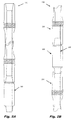
- FIG. 2A shows one exemplary drill string 200 with an amplifier booster sub 205, in accordance with certain embodiments of the present disclosure.
- the drill string 200 depicted may be part of a larger drill string assembly that, for example, may be suspended in a wellbore by a derrick (not shown).
- the drill string 200 may include a series of coupled sections.
- the amplifier booster sub 205 may be an intermediate section coupled to an upper section 210 and a lower section 215.
- an armored coaxial cable 220 may run through at least a portion of the drill string 200.
- the amplifier booster sub 205 may have any suitable position with a drill string.
- Figure 2B shows another exemplary drill string 250 with an amplifier booster sub 205, in accordance with certain embodiments of the present disclosure. As depicted, the amplifier booster sub 205 may be at a lower position in the drill string 250, rather than being in an intermediate position as shown in Figure 2A .
- an algorithm may define the boundary condition(s) where an amplifier booster may best be placed.
- the algorithm may indicate an optimal placement where the signal strength reaches the pre-defined boundary condition(s).
- the booster joint/amplifier system may include transceivers capable of receiving an incoming data signal and re-strengthening the received signal to its pre-defined strength; it is then transmitted to the next segment.
- the booster joint/amplifier system may be a complex structure that incorporates bit-encoding/decoding techniques to ensure the accuracy of the signal and the continuity of the transmission. Losses during the bidirectional signal transmission may be calculated. These losses may include Ohmic, attenuation, hysteresis, eddy, and induction losses.
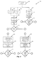
- Figure 3 depicts a flow diagram for an example method 300, in accordance with certain embodiments of the present disclosure. Teachings of the present disclosure may be utilized in a variety of implementations. As such, the order of the steps comprising the method 300 may depend on the implementation chosen.
- the method 300 may begin at step 302 with the selection of a particular segment of the drill string.
- Ohmic and coupling losses may be calculated across the segment, and the induction (hysteresis and eddy) losses maybe calculated at each tool joint junction.
- the power losses and the power at the end of the segment may be determined. The total power at the junction may be deduced, and, at step 312, it may be determined whether or not the signal remained at an acceptable level.
- attenuation losses may be calculated across the segment, and the signal strength at the end of the segment may be determined.
- the current power and signal specification may be maintained and losses may be calculated till the end of the next drill component, as indicated by step 320.
- the signal and power strength calculations and checks may continue, looping back to step 320 while threshold conditions are met.
- step 326 if the power and/or actual signal strength fail to meet a threshold, the signal and/or the power of the system may be strengthened back to initial conditions and the losses at the end of the next segment may be calculated. As indicated by steps 328 and 330, the calculations and checks of the signal and power strength at the end of the next segment may continue, looping back to step 326 until threshold conditions are met.
- booster/amplifiers may be positioned to re-strengthen the signal and retransmit it further toward the surface.
- the process may be continued throughout the drill string length until the transmitted signal from the MWD tool suite reaches the surface receivers with suitable power and signal strength.
- the surface receivers then may transmit the signal using wireless radio frequency system to data processing units, which may then harvest the incoming signal and convert it into logs or other pertinent information.
- FIG 4A is a partial cross-sectional illustration of an example power generator 400, in accordance with certain embodiments of the present disclosure.
- the power generator 400 includes an outer body 405 with a bore 410 running therethrough.
- the outer body 405 may be a sub or any suitable section of a drill string, and is more generally tubular about a flowway.
- the power generator 400 further includes one or more magnetostrictive elements 415.
- the magnetostrictive element 415 includes magnetostrictive material and is disposed in the power generator 400 in any suitable manner.
- the magnetostrictive element 415 may be embedded, attached to, affixed to, or otherwise coupled to the outer body 405.
- the magnetostrictive element 415 may be embedded along the side of the body of the booster sub.
- the magnetostrictive element 415 may take any suitable form.
- the forms of the magnetostrictive element 415 about the bore 405 may include a cylinder, a non-continuous cylindrical form, a series of adjacent members, etc .
- An inner sleeve 420 may be disposed along the bore 410 of the outer body 405.
- the magnetostrictive element 415 may encircle at least a portion of the sleeve 120, partially surround the sleeve 120, or otherwise be disposed about the sleeve 120.
- the sleeve 420 may be rotatably mounted to the outer body 405 by way of the bearing mounts 425.
- the mounts 425 may be ball bearing mounts, roller bearing mounts, or any suitable mount facilitating or allowing rotation of the sleeve 420.
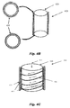
- Figure 4B is a simplified partial illustration of the power generator 400 showing top and bottom bearing mounts 425 for the sleeve 425, in accordance with certain embodiments of the present disclosure.
- FIG. 4C is another simplified partial illustration of the power generator 400, in accordance with certain embodiments of the present disclosure.
- the sleeve 420 includes one or more helical formations 421, which may for example be one or more of ribs, ridges or vanes, formed to engage and deflect at least a portion of the axial flow 411 of fluid through the bore 410 so that the sleeve 420 rotates.
- helical formations 421, and rotation 422 depicted are merely exemplary; any suitable sleeve, helical formation, pitch, and direction of rotation may be implemented, provided that the helical path is variable so that the pressures on the magnetostrictive element 415 can be modulated.
- the sleeve 420 may have a tight fit with the magnetostrictive element 415.
- the magnetostrictive element 415 may be in contact with the fluid.
- the helical formation 421 may be formed on the exterior of the sleeve 415, allowing fluid flow between the ridges.
- the frictional force and the hydraulic force based on the motion may be used to strain the magnetostrictive element 415.
- the sleeve 420 may be a rotating impeller type shaft that may rotate as the mud passes through the pipe. This may cause stress to be applied to the side of the magnetostrictive materials embedded on the side of the housing.
- the pressure applied to the polarized crystals may produce a mechanical deformation which in turn results in an electrical charge.
- the magnetostrictive material in the magnetostrictive element 415 uses the strain energy to generate an electrical charge distribution producing a magnetic field to be converted to electrical energy. Accordingly, the rotation of the sleeve 410 is converted into mechanical stress and further is converted into electrical charge through the use of magnetostrictive material 415 embedded inside the housing.
- One or more conductors may be disposed proximate to the material 415 and coupled to the material 415 to allow current to be induced, which includes being coupled in direct contact or coupled magnetically or inductively, for example.
- a conductor loop may be disposed in any suitable position in the magnetic circuit. For example, one or more wire coils may wound around, positioned above, positioned below, or positioned on the side of the magnetostrictive material 415.
- FIG. 5 depicts a flow diagram for an example method 500 of generating power, in accordance with certain embodiments of the present disclosure.
- the method 500 may begin at step 502 with fluid flow through the power generator.
- the fluid may be drilling mud.
- a pressure differential is created due at least in part to the helical formations and consequent rotation of the power generator.
- the pressure results in strains of the magnetostrictive material, and the strain shifts the magnetic domain of the material, creating electrical charge to provide an electrical power output.
- the magnetostrictive is a transition element between the mechanical and electrical domains.
- the electrical charge may be rectified and regulated to provide a reliable power supply.
- the power may be stored, e.g ., in a battery.
- Figure 6 shows an example of an equivalent circuit 600 between the mechanical and the electrical domains, in accordance with certain embodiments of the present disclosure.
- the input force F and voltage V across the magnetostrictive material may be the generalized effort variables, whereas the speed N and current I may be the generalized flow variables.
- the transfer of energy from the magnetostrictive material to a storage element (not shown) such as a battery may be facilitated in any suitable manner.
- the fluid energy may be used to convert magnetic and/or electric energy which is further used to power the booster/amplifier/repeater sub.
- Energy may be reclaimed from the strain energy induced by the rotation of a shaft placed inside the sub. The energy may be converted to useful electrical energy based on magnetostrictive principles.
- Figure 7 depicts an example magnetostrictive voltage output diagram 700, in accordance with certain embodiments of the present disclosure.
Description
- The present disclosure relates to power generators for booster amplifier systems and, more particularly, to providing electrical power to boost amplifier systems for downhole tools utilizing magnetostrictive materials.
- Data transmission from downhole tools to the surface may be extremely important to drilling engineers for real-time decision making and well economics. With new advances and innovations in downhole technologies, particularly in the areas of drilling optimization and MWD/LWD (measurement while drilling/logging while drilling) technologies, the current data transmission rates may be insufficient for the complete use of all downhole data that can be acquired. Digitization of transmission systems can increase the overall efficiency and accuracy of data acquisition systems. The benefits include increased reliability and large volumes of data on which to base current and future decisions. With its innovative technology, a high-speed wired telemetry drill pipe system can achieve this. A network, consisting of embedded wires along the drill string, can achieve higher transmission rates from downhole tools to the surface in real time; it can enable the complete use of technological advances in approximately the same amount of rig time as is required with mud pulse or electromagnetic telemetry systems. However, signal loss may occur in certain applications.
- European patent application publication no.
EP 0080224 A2 describes means for generating electric energy in a borehole during drilling thereof. International patent application publication no.WO 00/46479 A1 - The invention provides, in one aspect, a system to harvest energy from fluid flow, the system comprising an outer body comprising a flowway; an inner sleeve rotatably coupled to the outer body; and a magnetostrictive material disposed proximate to the inner sleeve, arranged to be strained due to a rotation of the inner sleeve in response to a fluid flow in the flowway, wherein the inner sleeve comprises a variable helical formation extending from a surface of the inner sleeve so that at least a portion of the fluid flow impinges upon the helical formation and the pressures on the magnetostrictive material can be modulated.
- The invention also provides, in another aspect, a method of harvesting energy from fluid flow, the method comprising providing an outer body comprising a flowway; providing an inner sleeve rotatably coupled to the outer body; providing a magnetostrictive material disposed proximate to the inner sleeve to be strained due to a rotation of the inner sleeve in response to a fluid flow in the flowway the inner sleeve comprising a helical formation extending from a surface of the inner sleeve; providing a conductor disposed proximate to the magnetostrictive material; rotating the inner sleeve, wherein the rotation strains the magnetostrictive material, generating an electrical current in the conductor; providing the fluid flow in the flowway so that at least a portion of the fluid flow impinges upon the helical formation; and varying a helical path of the helical formation so that pressures on the magnetostrictive material can be modulated.
- In order that the invention will be more readily understood, embodiments thereof will now be described, by way of example only, with reference to the drawings, and in which:-
-
Figure 1 illustrates a coil system of a high-speed wired telemetry system that may be installed within a drill string, in accordance with certain embodiments of the present disclosure; -
Figures 2A and 2B show exemplary drill strings with amplifier booster subs, in accordance with certain embodiments of the present disclosure; -
Figure 3 depicts a flow diagram for an example method, in accordance with certain embodiments of the present disclosure; -
Figure 4A is a partial cross-sectional illustration of an example power generator, in accordance with certain embodiments of the present disclosure; -
Figures 4B and 4C are simplified partial illustrations of the example power generator ofFigure 4A , in accordance with certain embodiments of the present disclosure; -
Figure 5 depicts a flow diagram for an example method of generating power, in accordance with certain embodiments of the present disclosure; -
Figure 6 is a diagram of an example of an equivalent circuit between the mechanical and the electrical domains, in accordance with certain embodiments of the present disclosure; and -
Figure 7 depicts an example magnetostrictive voltage output diagram, in accordance with certain embodiments of the present disclosure. - While embodiments of this disclosure have been depicted and described and are defined by reference to exemplary embodiments of the disclosure, such references do not imply a limitation on the disclosure, and no such limitation is to be inferred. The subject matter disclosed is capable of considerable modification, alteration, and equivalents in form and function, as will occur to those skilled in the pertinent art and having the benefit of this disclosure. The depicted and described embodiments of this disclosure are examples only and the invention is defined by the claims.
- The present disclosure relates to power generators for booster amplifier systems and, more particularly, to providing electrical power to boost amplifier systems for downhole tools utilizing magnetostrictive materials.
- Illustrative embodiments of the present invention are described in detail herein. In the interest of clarity, not all features of an actual implementation may be described in this specification. It will of course be appreciated that in the development of any such actual embodiment, numerous implementation-specific decisions must be made to achieve the specific implementation goals, which will vary from one implementation to another. Moreover, it will be appreciated that such a development effort might be complex and time-consuming, but would nevertheless be a routine undertaking for those of ordinary skill in the art having the benefit of the present disclosure.
- In certain embodiments according to the present disclosure, magnetostrictive technology is capable of generating electrical power during the process of drilling a borehole by using the mechanical energy generated in a downhole drilling assembly. Magnetostrictive materials have the ability to convert kinetic/elastic energy into magnetic energy that may be used to generate electrical power. Magnetostrictive materials have the property that, when strain is induced in the material, the change in linear dimensions produces a corresponding change in magnetic field about the material. In other words, mechanical loads can deform the material and thereby rotate magnetic domains. The change of the magnetic flux can be used to generate electrical power. A suitable material for the magnetostrictive material may be Terfenol-D, available from Etrema Products, Inc. Various materials, e.g., iron and iron alloys such as Terfenol, may provide suitable magnetostrictive and giant magnetostrictive responses. These materials normally respond to a force applied to their mechanical connection by creating a magnetic field which can be detected, for example, by a surrounding coil.
- In certain embodiments of the present disclosure, a high-speed wired telemetry system may be installed within a drill string. In certain embodiments, this system may use no moving parts. In certain embodiments, the drill string may operate at a high bit rate, e.g., approximately 57,000 bits per second. Such a high bit rate may be advantageous as it may enable more information to be gathered in the same amount of rig time than is possible with the mud, electromagnetic, or acoustic telemetry methods. The quality of the information obtained may be very high. The logging information obtained may enable an analysis of the formation, and the high resolution images (e.g., 8 to 16 gamma ray pictures) may be useful to geologists and geophysicists. In certain embodiments, these methods may also enable better statistical analyses to be performed. In certain embodiments, many multisensors may be placed to retrieve the information downhole. These sensors can play an effective role in data transmission and provide a foundation of independent data transmission architecture.
-
Figure 1 illustrates acoil system 100 of a high-speed wired telemetry system that may be installed within a drill string. In the example depicted, acoil 105 may be installed with one drill string section;coil pairs coil 120 may be installed with a lower drill string section. As such, the coils of a coil pair may be directly wired to relay signals across one or more drill string sections. And adjacent coils may transfer signals across drill string section junctions. A coil on a sending side may energize the coil on a receiving side, which enables the communication between two drill string components. Such wired telemetry drill pipes may have data transmission rates of approximately 57,000 bits/second or even up to approximately 2 megabits/second. This method may work well for underbalanced drilling where mud pulse telemetry may become unusable. - In some applications, the signal may undergo attenuation and experience material losses along the way. The signal losses may be calculated along each drill string segment, and the algorithm may maintain a continuous measurement of the effective signal strength at the end of each segment. A power source or amplifier may be placed at depths where there will be an effective loss of signal. And, to prevent the loss of signals, amplifier/booster subs may be placed along the string so that data signal transmission from downhole to the surface systems is enabled. An accurately placed amplifier/booster system may be an essential part for the success of the wired telemetry system. It can address signal losses and can ensure that the integrity of essential signal parameters (such as bandwidth, bit accuracy, signal strength) remains consistent throughout the transmission path.
-
Figure 2A shows oneexemplary drill string 200 with anamplifier booster sub 205, in accordance with certain embodiments of the present disclosure. Thedrill string 200 depicted may be part of a larger drill string assembly that, for example, may be suspended in a wellbore by a derrick (not shown). Thedrill string 200 may include a series of coupled sections. As depicted, theamplifier booster sub 205 may be an intermediate section coupled to anupper section 210 and alower section 215. In certain embodiments, an armoredcoaxial cable 220 may run through at least a portion of thedrill string 200. - The
amplifier booster sub 205 may have any suitable position with a drill string.Figure 2B shows anotherexemplary drill string 250 with anamplifier booster sub 205, in accordance with certain embodiments of the present disclosure. As depicted, theamplifier booster sub 205 may be at a lower position in thedrill string 250, rather than being in an intermediate position as shown inFigure 2A . - In certain embodiments, an algorithm may define the boundary condition(s) where an amplifier booster may best be placed. The algorithm may indicate an optimal placement where the signal strength reaches the pre-defined boundary condition(s). In certain embodiments, the booster joint/amplifier system may include transceivers capable of receiving an incoming data signal and re-strengthening the received signal to its pre-defined strength; it is then transmitted to the next segment. In certain embodiments, the booster joint/amplifier system may be a complex structure that incorporates bit-encoding/decoding techniques to ensure the accuracy of the signal and the continuity of the transmission. Losses during the bidirectional signal transmission may be calculated. These losses may include Ohmic, attenuation, hysteresis, eddy, and induction losses.
- One focus of a method of the present disclosure is on ensuring that the transmitting signal would have an acceptable power range at all times, which may be approximately 90% of the maximum power possible, for example.
Figure 3 depicts a flow diagram for anexample method 300, in accordance with certain embodiments of the present disclosure. Teachings of the present disclosure may be utilized in a variety of implementations. As such, the order of the steps comprising themethod 300 may depend on the implementation chosen. - According certain embodiments, the
method 300 may begin atstep 302 with the selection of a particular segment of the drill string. Atsteps steps step 312, it may be determined whether or not the signal remained at an acceptable level. Likewise, atsteps step 318, it may be determined whether the actual signal strength is greater than a minimum signal strength. If the power and/or the actual signal strength are above the minimum thresholds, then the current power and signal specification may be maintained and losses may be calculated till the end of the next drill component, as indicated bystep 320. As indicated bysteps - As indicated at
step 326, if the power and/or actual signal strength fail to meet a threshold, the signal and/or the power of the system may be strengthened back to initial conditions and the losses at the end of the next segment may be calculated. As indicated bysteps - Thus, with boundary conditions defined at corresponding tool joints, booster/amplifiers may be positioned to re-strengthen the signal and retransmit it further toward the surface. The process may be continued throughout the drill string length until the transmitted signal from the MWD tool suite reaches the surface receivers with suitable power and signal strength. The surface receivers then may transmit the signal using wireless radio frequency system to data processing units, which may then harvest the incoming signal and convert it into logs or other pertinent information.
-
Figure 4A is a partial cross-sectional illustration of anexample power generator 400, in accordance with certain embodiments of the present disclosure. Thepower generator 400 includes anouter body 405 with abore 410 running therethrough. Theouter body 405 may be a sub or any suitable section of a drill string, and is more generally tubular about a flowway. Thepower generator 400 further includes one or moremagnetostrictive elements 415. Themagnetostrictive element 415 includes magnetostrictive material and is disposed in thepower generator 400 in any suitable manner. By way of non-limiting example, themagnetostrictive element 415 may be embedded, attached to, affixed to, or otherwise coupled to theouter body 405. In certain embodiments of a booster/amplifier sub, themagnetostrictive element 415 may be embedded along the side of the body of the booster sub. Themagnetostrictive element 415 may take any suitable form. By way of non-limiting example, the forms of themagnetostrictive element 415 about thebore 405 may include a cylinder, a non-continuous cylindrical form, a series of adjacent members, etc. Aninner sleeve 420 may be disposed along thebore 410 of theouter body 405. In various embodiments, themagnetostrictive element 415 may encircle at least a portion of thesleeve 120, partially surround thesleeve 120, or otherwise be disposed about thesleeve 120. - The
sleeve 420 may be rotatably mounted to theouter body 405 by way of the bearing mounts 425. In certain embodiments, themounts 425 may be ball bearing mounts, roller bearing mounts, or any suitable mount facilitating or allowing rotation of thesleeve 420.Figure 4B is a simplified partial illustration of thepower generator 400 showing top and bottom bearing mounts 425 for thesleeve 425, in accordance with certain embodiments of the present disclosure. -
Figure 4C is another simplified partial illustration of thepower generator 400, in accordance with certain embodiments of the present disclosure. Thesleeve 420 includes one or morehelical formations 421, which may for example be one or more of ribs, ridges or vanes, formed to engage and deflect at least a portion of theaxial flow 411 of fluid through thebore 410 so that thesleeve 420 rotates. It should be understood that thesleeve 420,helical formations 421, androtation 422 depicted are merely exemplary; any suitable sleeve, helical formation, pitch, and direction of rotation may be implemented, provided that the helical path is variable so that the pressures on themagnetostrictive element 415 can be modulated. - The
sleeve 420 may have a tight fit with themagnetostrictive element 415. In certain embodiments, themagnetostrictive element 415 may be in contact with the fluid. For example, thehelical formation 421 may be formed on the exterior of thesleeve 415, allowing fluid flow between the ridges. Withsuitable fluid flow 411 androtation 422 of thesleeve 420 in the stationaryouter body 405, the frictional force and the hydraulic force based on the motion may be used to strain themagnetostrictive element 415. In certain embodiments, thesleeve 420 may be a rotating impeller type shaft that may rotate as the mud passes through the pipe. This may cause stress to be applied to the side of the magnetostrictive materials embedded on the side of the housing. - The pressure applied to the polarized crystals may produce a mechanical deformation which in turn results in an electrical charge. In other words, the magnetostrictive material in the
magnetostrictive element 415 uses the strain energy to generate an electrical charge distribution producing a magnetic field to be converted to electrical energy. Accordingly, the rotation of thesleeve 410 is converted into mechanical stress and further is converted into electrical charge through the use ofmagnetostrictive material 415 embedded inside the housing. One or more conductors may be disposed proximate to thematerial 415 and coupled to thematerial 415 to allow current to be induced, which includes being coupled in direct contact or coupled magnetically or inductively, for example. A conductor loop may be disposed in any suitable position in the magnetic circuit. For example, one or more wire coils may wound around, positioned above, positioned below, or positioned on the side of themagnetostrictive material 415. -
Figure 5 depicts a flow diagram for anexample method 500 of generating power, in accordance with certain embodiments of the present disclosure. Themethod 500 may begin atstep 502 with fluid flow through the power generator. In certain embodiments, the fluid may be drilling mud. Atstep 504, a pressure differential is created due at least in part to the helical formations and consequent rotation of the power generator. Atstep 506, the pressure results in strains of the magnetostrictive material, and the strain shifts the magnetic domain of the material, creating electrical charge to provide an electrical power output. As such, the magnetostrictive is a transition element between the mechanical and electrical domains. Thus, in response the pressure, strain energy is converted to electrical energy. In certain embodiments, atstep 508, the electrical charge may be rectified and regulated to provide a reliable power supply. And in certain embodiments, atstep 510, the power may be stored, e.g., in a battery. -
Figure 6 shows an example of anequivalent circuit 600 between the mechanical and the electrical domains, in accordance with certain embodiments of the present disclosure. In the illustrated embodiment, the input force F and voltage V across the magnetostrictive material may be the generalized effort variables, whereas the speed N and current I may be the generalized flow variables. In the mechanical domain, Rm may be the mechanical damping; Cm may be the compliance of the housing. In the electrical domain, Cp may be the capacitance; Rc may be dielectric loss. The transfer of energy from the magnetostrictive material to a storage element (not shown) such as a battery may be facilitated in any suitable manner. - Accordingly, in certain embodiments implemented in a booster/amplifier/repeater sub, as fluid flows through the sub, the fluid energy may be used to convert magnetic and/or electric energy which is further used to power the booster/amplifier/repeater sub. Energy may be reclaimed from the strain energy induced by the rotation of a shaft placed inside the sub. The energy may be converted to useful electrical energy based on magnetostrictive principles.
-
Figure 7 depicts an example magnetostrictive voltage output diagram 700, in accordance with certain embodiments of the present disclosure. In certain embodiments, an applied force will produce a voltage that may be expressed by:

- The voltage sensitivity may be defined as the field produced per unit stress applied and may be given by the following equation:


- t = thickness of the transducer;
- l = length;
- w = width;
- ε = dielectric constant;
- C = capacitance formed in the transducer; and
- Q = charge developed.
- Therefore, the present invention is well adapted to attain the ends and advantages mentioned as well as those that are inherent therein. The particular embodiments disclosed above are illustrative only, as the present invention may be modified and practiced in different but equivalent manners apparent to those skilled in the art having the benefit of the teachings herein. Furthermore, no limitations are intended to the details of construction or design herein shown, other than as described in the claims below. It is therefore evident that the particular illustrative embodiments disclosed above may be altered or modified and all such variations are considered within the scope of the present invention. Also, the terms in the claims have their plain, ordinary meaning unless otherwise explicitly and clearly defined by the patentee. The indefinite articles "a" or "an," as used in the claims, are defined herein to mean one or more than one of the element that it introduces.
Claims (10)
- A system (400) to harvest energy from fluid flow, the system comprising:an outer body (405) comprising a flowway;an inner sleeve (420) rotatably coupled to the outer body; anda magnetostrictive material (415) disposed proximate to the inner sleeve, arranged to be strained due to a rotation of the inner sleeve in response to a fluid flow in the flowway, characterized in that the inner sleeve comprises a variable helical formation (421) extending from a surface of the inner sleeve so that at least a portion of the fluid flow impinges upon the helical formation and the pressures on the magnetostrictive material can be modulated.
- The system to harvest energy from fluid flow of claim 1, further comprising a conductor disposed proximate to the magnetostrictive material, wherein an electrical current is produced in the conductor due to a strain in the magnetostrictive material.
- The system to harvest energy from fluid flow of claim 1 or claim 2, wherein the magnetostrictive material encircles the inner sleeve.
- The system to harvest energy from fluid flow of claim 1 or claim 2, wherein the magnetostrictive material partially surrounds the inner sleeve.
- A drill string apparatus (200), comprising a system according to any preceding claim, wherein the inner sleeve is a shaft at least partially housed in the outer body.
- The drill string apparatus of claim 5, wherein the helical formation extends from an inner surface of the shaft so that at least a portion of the fluid flow impinges upon the helical formation.
- The drill string apparatus of claim 5, wherein the helical formation extends from an outer surface of the shaft so that at least a portion of the fluid flow impinges upon the helical formation.
- The drill string apparatus of any one of claims 5 to 7, when dependent on claim 2, further comprising an amplifier booster sub (205), which apparatus is arranged such that the electrical current supplies power to the amplifier booster sub.
- A method of harvesting energy from fluid flow, the method comprising:providing an outer body (405) comprising a flowway;providing an inner sleeve (420) rotatably coupled to the outer body;providing a magnetostrictive material (415) disposed proximate to the inner sleeve to be strained due to a rotation of the inner sleeve in response to a fluid flow in the flowway, the inner sleeve comprising a helical formation extending from a surface of the inner sleeve;providing a conductor disposed proximate to the magnetostrictive material;rotating the inner sleeve, wherein the rotation strains the magnetostrictive material, generating an electrical current in the conductor;providing the fluid flow in the flowway so that at least a portion of the fluid flow impinges upon the helical formation; andvarying a helical path of the helical formation so that pressures on the magnetostrictive material can be modulated.
- The method of harvesting energy from fluid flow of claim 9, further comprising powering an amplifier booster sub (205) with the electrical current.
Applications Claiming Priority (2)
| Application Number | Priority Date | Filing Date | Title |
|---|---|---|---|
| US201161451505P | 2011-03-10 | 2011-03-10 | |
| US13/290,484 US8686587B2 (en) | 2011-03-10 | 2011-11-07 | Power generator for booster amplifier systems |
Publications (3)
| Publication Number | Publication Date |
|---|---|
| EP2501032A2 EP2501032A2 (en) | 2012-09-19 |
| EP2501032A3 EP2501032A3 (en) | 2014-06-25 |
| EP2501032B1 true EP2501032B1 (en) | 2016-06-01 |
Family
ID=45894122
Family Applications (1)
| Application Number | Title | Priority Date | Filing Date |
|---|---|---|---|
| EP12158781.0A Active EP2501032B1 (en) | 2011-03-10 | 2012-03-09 | Power generator for booster amplifier systems |
Country Status (2)
| Country | Link |
|---|---|
| US (1) | US8686587B2 (en) |
| EP (1) | EP2501032B1 (en) |
Families Citing this family (6)
| Publication number | Priority date | Publication date | Assignee | Title |
|---|---|---|---|---|
| EP2972516B1 (en) * | 2013-03-14 | 2022-04-27 | Prime Downhole Manufacturing LLC | Composite isolation joint for gap sub or internal gap |
| CN104612896A (en) * | 2014-12-12 | 2015-05-13 | 西北工业大学 | Offshore wind power generation typhoon-resistance control system |
| GB2554880A (en) * | 2016-10-11 | 2018-04-18 | Swellfix Uk Ltd | Downhole devices, associated apparatus and methods |
| US11686196B2 (en) | 2019-12-19 | 2023-06-27 | Saudi Arabian Oil Company | Downhole actuation system and methods with dissolvable ball bearing |
| US11078780B2 (en) | 2019-12-19 | 2021-08-03 | Saudi Arabian Oil Company | Systems and methods for actuating downhole devices and enabling drilling workflows from the surface |
| US11230918B2 (en) | 2019-12-19 | 2022-01-25 | Saudi Arabian Oil Company | Systems and methods for controlled release of sensor swarms downhole |
Citations (1)
| Publication number | Priority date | Publication date | Assignee | Title |
|---|---|---|---|---|
| WO2000046479A1 (en) * | 1999-02-01 | 2000-08-10 | Shell Internationale Research Maatschappij B.V. | Multilateral well and electrical transmission system |
Family Cites Families (11)
| Publication number | Priority date | Publication date | Assignee | Title |
|---|---|---|---|---|
| DE3277825D1 (en) * | 1981-11-24 | 1988-01-21 | Shell Int Research | Means for generating electric energy in a borehole during drilling thereof |
| EP0526604B1 (en) * | 1991-02-14 | 1996-04-24 | VOWLES, Alan Keith | Wave energy generator |
| US6279651B1 (en) * | 1999-07-20 | 2001-08-28 | Halliburton Energy Services, Inc. | Tool for managing fluid flow in a well |
| EP1402145B2 (en) * | 2002-05-15 | 2010-03-17 | Baker Hughes Incorporated | Closed loop drilling assembly with electronics outside a non-rotating sleeve |
| US7808236B1 (en) * | 2002-12-09 | 2010-10-05 | Ferro Solutions, Inc. | Energy harvester utilizing external magnetic field |
| US7816797B2 (en) | 2009-01-07 | 2010-10-19 | Oscilla Power Inc. | Method and device for harvesting energy from ocean waves |
| US7816799B2 (en) * | 2009-07-22 | 2010-10-19 | Oscilla Power Inc. | Method and device for energy generation |
| US7816833B2 (en) | 2009-11-20 | 2010-10-19 | Oscilla Power Inc. | Method and device for energy generation |
| US8097990B2 (en) | 2010-02-18 | 2012-01-17 | Oscilla Power Inc. | Electrical generator that utilizes rotational to linear motion conversion |
| US8633610B2 (en) * | 2011-03-10 | 2014-01-21 | Halliburton Energy Services, Inc. | Systems and methods of harvesting energy in a wellbore |
| US8604632B2 (en) * | 2011-03-10 | 2013-12-10 | Halliburton Energy Services, Inc. | Systems and methods of harvesting energy in a wellbore |
-
2011
- 2011-11-07 US US13/290,484 patent/US8686587B2/en active Active
-
2012
- 2012-03-09 EP EP12158781.0A patent/EP2501032B1/en active Active
Patent Citations (1)
| Publication number | Priority date | Publication date | Assignee | Title |
|---|---|---|---|---|
| WO2000046479A1 (en) * | 1999-02-01 | 2000-08-10 | Shell Internationale Research Maatschappij B.V. | Multilateral well and electrical transmission system |
Also Published As
| Publication number | Publication date |
|---|---|
| US20120228876A1 (en) | 2012-09-13 |
| US8686587B2 (en) | 2014-04-01 |
| EP2501032A3 (en) | 2014-06-25 |
| EP2501032A2 (en) | 2012-09-19 |
Similar Documents
| Publication | Publication Date | Title |
|---|---|---|
| US11828172B2 (en) | Communication networks, relay nodes for communication networks, and methods of transmitting data among a plurality of relay nodes | |
| EP2501032B1 (en) | Power generator for booster amplifier systems | |
| US8657035B2 (en) | Systems and methods for providing wireless power transmissions and tuning a transmission frequency | |
| US8519865B2 (en) | Downhole coils | |
| JP5384109B2 (en) | Surface communication device and method used for excavation string telemetry | |
| US8134476B2 (en) | Apparatus and methods for self-powered communication and sensor network | |
| US8284075B2 (en) | Apparatus and methods for self-powered communication and sensor network | |
| US8890341B2 (en) | Harvesting energy from a drillstring | |
| RU2413841C2 (en) | System for double-sided telemetry of drill string for measurement and control of drilling | |
| US20080012569A1 (en) | Downhole Coils | |
| US8544534B2 (en) | Power systems for wireline well service using wired pipe string | |
| EP0636763A2 (en) | Method and apparatus for electric/acoustic telemetry in a well | |
| US8633610B2 (en) | Systems and methods of harvesting energy in a wellbore | |
| JP2009503308A (en) | Interactive drilling string telemetry system for measurement and drilling control | |
| CN1975106A (en) | Wireless electromagnetic telemetry system and method for bottomhole assembly | |
| US20150090444A1 (en) | Power systems for wireline well service using wired pipe string | |
| CN101253304A (en) | Bi-directional drill string telemetry for measurement and drilling control | |
| WO2004113677A1 (en) | Apparatus and method for self-powered communication and sensor network | |
| US20100133833A1 (en) | Electrical power generation for downhole exploration or production devices | |
| US10358913B2 (en) | Motor MWD device and methods | |
| EP2196620B1 (en) | A micro-logging system and method | |
| RU2279542C2 (en) | Downhole information transmission device | |
| AU2017320734B2 (en) | Communication networks, relay nodes for communication networks, and methods of transmitting data among a plurality of relay nodes | |
| EP2196621B1 (en) | A micro-logging system and method | |
| US11428841B2 (en) | Retaining a plurality of ferrite objects in an antenna of a downhole tool |
Legal Events
| Date | Code | Title | Description |
|---|---|---|---|
| PUAI | Public reference made under article 153(3) epc to a published international application that has entered the european phase |
Free format text: ORIGINAL CODE: 0009012 |
|
| AK | Designated contracting states |
Kind code of ref document: A2 Designated state(s): AL AT BE BG CH CY CZ DE DK EE ES FI FR GB GR HR HU IE IS IT LI LT LU LV MC MK MT NL NO PL PT RO RS SE SI SK SM TR |
|
| AX | Request for extension of the european patent |
Extension state: BA ME |
|
| REG | Reference to a national code |
Ref country code: DE Ref legal event code: R079 Ref document number: 602012019103 Country of ref document: DE Free format text: PREVIOUS MAIN CLASS: H02N0002000000 Ipc: H02N0002180000 |
|
| PUAL | Search report despatched |
Free format text: ORIGINAL CODE: 0009013 |
|
| AK | Designated contracting states |
Kind code of ref document: A3 Designated state(s): AL AT BE BG CH CY CZ DE DK EE ES FI FR GB GR HR HU IE IS IT LI LT LU LV MC MK MT NL NO PL PT RO RS SE SI SK SM TR |
|
| AX | Request for extension of the european patent |
Extension state: BA ME |
|
| RIC1 | Information provided on ipc code assigned before grant |
Ipc: E21B 41/00 20060101ALI20140520BHEP Ipc: H02N 2/18 20060101AFI20140520BHEP Ipc: H01L 41/12 20060101ALI20140520BHEP Ipc: E21B 17/02 20060101ALI20140520BHEP |
|
| 17P | Request for examination filed |
Effective date: 20141029 |
|
| RBV | Designated contracting states (corrected) |
Designated state(s): AL AT BE BG CH CY CZ DE DK EE ES FI FR GB GR HR HU IE IS IT LI LT LU LV MC MK MT NL NO PL PT RO RS SE SI SK SM TR |
|
| 17Q | First examination report despatched |
Effective date: 20150527 |
|
| GRAP | Despatch of communication of intention to grant a patent |
Free format text: ORIGINAL CODE: EPIDOSNIGR1 |
|
| INTG | Intention to grant announced |
Effective date: 20151117 |
|
| GRAS | Grant fee paid |
Free format text: ORIGINAL CODE: EPIDOSNIGR3 |
|
| GRAA | (expected) grant |
Free format text: ORIGINAL CODE: 0009210 |
|
| AK | Designated contracting states |
Kind code of ref document: B1 Designated state(s): AL AT BE BG CH CY CZ DE DK EE ES FI FR GB GR HR HU IE IS IT LI LT LU LV MC MK MT NL NO PL PT RO RS SE SI SK SM TR |
|
| REG | Reference to a national code |
Ref country code: GB Ref legal event code: FG4D |
|
| REG | Reference to a national code |
Ref country code: CH Ref legal event code: EP Ref country code: AT Ref legal event code: REF Ref document number: 804416 Country of ref document: AT Kind code of ref document: T Effective date: 20160615 |
|
| REG | Reference to a national code |
Ref country code: IE Ref legal event code: FG4D |
|
| REG | Reference to a national code |
Ref country code: DE Ref legal event code: R096 Ref document number: 602012019103 Country of ref document: DE |
|
| REG | Reference to a national code |
Ref country code: NO Ref legal event code: T2 Effective date: 20160601 |
|
| REG | Reference to a national code |
Ref country code: LT Ref legal event code: MG4D |
|
| REG | Reference to a national code |
Ref country code: NL Ref legal event code: MP Effective date: 20160601 |
|
| PG25 | Lapsed in a contracting state [announced via postgrant information from national office to epo] |
Ref country code: LT Free format text: LAPSE BECAUSE OF FAILURE TO SUBMIT A TRANSLATION OF THE DESCRIPTION OR TO PAY THE FEE WITHIN THE PRESCRIBED TIME-LIMIT Effective date: 20160601 Ref country code: FI Free format text: LAPSE BECAUSE OF FAILURE TO SUBMIT A TRANSLATION OF THE DESCRIPTION OR TO PAY THE FEE WITHIN THE PRESCRIBED TIME-LIMIT Effective date: 20160601 |
|
| REG | Reference to a national code |
Ref country code: AT Ref legal event code: MK05 Ref document number: 804416 Country of ref document: AT Kind code of ref document: T Effective date: 20160601 |
|
| PG25 | Lapsed in a contracting state [announced via postgrant information from national office to epo] |
Ref country code: NL Free format text: LAPSE BECAUSE OF FAILURE TO SUBMIT A TRANSLATION OF THE DESCRIPTION OR TO PAY THE FEE WITHIN THE PRESCRIBED TIME-LIMIT Effective date: 20160601 Ref country code: ES Free format text: LAPSE BECAUSE OF FAILURE TO SUBMIT A TRANSLATION OF THE DESCRIPTION OR TO PAY THE FEE WITHIN THE PRESCRIBED TIME-LIMIT Effective date: 20160601 Ref country code: LV Free format text: LAPSE BECAUSE OF FAILURE TO SUBMIT A TRANSLATION OF THE DESCRIPTION OR TO PAY THE FEE WITHIN THE PRESCRIBED TIME-LIMIT Effective date: 20160601 Ref country code: RS Free format text: LAPSE BECAUSE OF FAILURE TO SUBMIT A TRANSLATION OF THE DESCRIPTION OR TO PAY THE FEE WITHIN THE PRESCRIBED TIME-LIMIT Effective date: 20160601 Ref country code: GR Free format text: LAPSE BECAUSE OF FAILURE TO SUBMIT A TRANSLATION OF THE DESCRIPTION OR TO PAY THE FEE WITHIN THE PRESCRIBED TIME-LIMIT Effective date: 20160902 Ref country code: HR Free format text: LAPSE BECAUSE OF FAILURE TO SUBMIT A TRANSLATION OF THE DESCRIPTION OR TO PAY THE FEE WITHIN THE PRESCRIBED TIME-LIMIT Effective date: 20160601 Ref country code: SE Free format text: LAPSE BECAUSE OF FAILURE TO SUBMIT A TRANSLATION OF THE DESCRIPTION OR TO PAY THE FEE WITHIN THE PRESCRIBED TIME-LIMIT Effective date: 20160601 |
|
| PG25 | Lapsed in a contracting state [announced via postgrant information from national office to epo] |
Ref country code: RO Free format text: LAPSE BECAUSE OF FAILURE TO SUBMIT A TRANSLATION OF THE DESCRIPTION OR TO PAY THE FEE WITHIN THE PRESCRIBED TIME-LIMIT Effective date: 20160601 Ref country code: CZ Free format text: LAPSE BECAUSE OF FAILURE TO SUBMIT A TRANSLATION OF THE DESCRIPTION OR TO PAY THE FEE WITHIN THE PRESCRIBED TIME-LIMIT Effective date: 20160601 Ref country code: EE Free format text: LAPSE BECAUSE OF FAILURE TO SUBMIT A TRANSLATION OF THE DESCRIPTION OR TO PAY THE FEE WITHIN THE PRESCRIBED TIME-LIMIT Effective date: 20160601 Ref country code: IS Free format text: LAPSE BECAUSE OF FAILURE TO SUBMIT A TRANSLATION OF THE DESCRIPTION OR TO PAY THE FEE WITHIN THE PRESCRIBED TIME-LIMIT Effective date: 20161001 Ref country code: IT Free format text: LAPSE BECAUSE OF FAILURE TO SUBMIT A TRANSLATION OF THE DESCRIPTION OR TO PAY THE FEE WITHIN THE PRESCRIBED TIME-LIMIT Effective date: 20160601 Ref country code: SK Free format text: LAPSE BECAUSE OF FAILURE TO SUBMIT A TRANSLATION OF THE DESCRIPTION OR TO PAY THE FEE WITHIN THE PRESCRIBED TIME-LIMIT Effective date: 20160601 |
|
| PG25 | Lapsed in a contracting state [announced via postgrant information from national office to epo] |
Ref country code: PT Free format text: LAPSE BECAUSE OF FAILURE TO SUBMIT A TRANSLATION OF THE DESCRIPTION OR TO PAY THE FEE WITHIN THE PRESCRIBED TIME-LIMIT Effective date: 20161003 Ref country code: BE Free format text: LAPSE BECAUSE OF FAILURE TO SUBMIT A TRANSLATION OF THE DESCRIPTION OR TO PAY THE FEE WITHIN THE PRESCRIBED TIME-LIMIT Effective date: 20160601 Ref country code: SM Free format text: LAPSE BECAUSE OF FAILURE TO SUBMIT A TRANSLATION OF THE DESCRIPTION OR TO PAY THE FEE WITHIN THE PRESCRIBED TIME-LIMIT Effective date: 20160601 Ref country code: PL Free format text: LAPSE BECAUSE OF FAILURE TO SUBMIT A TRANSLATION OF THE DESCRIPTION OR TO PAY THE FEE WITHIN THE PRESCRIBED TIME-LIMIT Effective date: 20160601 Ref country code: AT Free format text: LAPSE BECAUSE OF FAILURE TO SUBMIT A TRANSLATION OF THE DESCRIPTION OR TO PAY THE FEE WITHIN THE PRESCRIBED TIME-LIMIT Effective date: 20160601 |
|
| REG | Reference to a national code |
Ref country code: DE Ref legal event code: R097 Ref document number: 602012019103 Country of ref document: DE |
|
| PLBE | No opposition filed within time limit |
Free format text: ORIGINAL CODE: 0009261 |
|
| STAA | Information on the status of an ep patent application or granted ep patent |
Free format text: STATUS: NO OPPOSITION FILED WITHIN TIME LIMIT |
|
| 26N | No opposition filed |
Effective date: 20170302 |
|
| PG25 | Lapsed in a contracting state [announced via postgrant information from national office to epo] |
Ref country code: DK Free format text: LAPSE BECAUSE OF FAILURE TO SUBMIT A TRANSLATION OF THE DESCRIPTION OR TO PAY THE FEE WITHIN THE PRESCRIBED TIME-LIMIT Effective date: 20160601 Ref country code: SI Free format text: LAPSE BECAUSE OF FAILURE TO SUBMIT A TRANSLATION OF THE DESCRIPTION OR TO PAY THE FEE WITHIN THE PRESCRIBED TIME-LIMIT Effective date: 20160601 |
|
| REG | Reference to a national code |
Ref country code: CH Ref legal event code: PL |
|
| PG25 | Lapsed in a contracting state [announced via postgrant information from national office to epo] |
Ref country code: MC Free format text: LAPSE BECAUSE OF FAILURE TO SUBMIT A TRANSLATION OF THE DESCRIPTION OR TO PAY THE FEE WITHIN THE PRESCRIBED TIME-LIMIT Effective date: 20160601 |
|
| REG | Reference to a national code |
Ref country code: IE Ref legal event code: MM4A |
|
| REG | Reference to a national code |
Ref country code: FR Ref legal event code: ST Effective date: 20171130 |
|
| PG25 | Lapsed in a contracting state [announced via postgrant information from national office to epo] |
Ref country code: LU Free format text: LAPSE BECAUSE OF NON-PAYMENT OF DUE FEES Effective date: 20170309 Ref country code: FR Free format text: LAPSE BECAUSE OF NON-PAYMENT OF DUE FEES Effective date: 20170331 |
|
| PG25 | Lapsed in a contracting state [announced via postgrant information from national office to epo] |
Ref country code: CH Free format text: LAPSE BECAUSE OF NON-PAYMENT OF DUE FEES Effective date: 20170331 Ref country code: IE Free format text: LAPSE BECAUSE OF NON-PAYMENT OF DUE FEES Effective date: 20170309 Ref country code: LI Free format text: LAPSE BECAUSE OF NON-PAYMENT OF DUE FEES Effective date: 20170331 |
|
| PG25 | Lapsed in a contracting state [announced via postgrant information from national office to epo] |
Ref country code: MT Free format text: LAPSE BECAUSE OF NON-PAYMENT OF DUE FEES Effective date: 20170309 |
|
| PG25 | Lapsed in a contracting state [announced via postgrant information from national office to epo] |
Ref country code: AL Free format text: LAPSE BECAUSE OF FAILURE TO SUBMIT A TRANSLATION OF THE DESCRIPTION OR TO PAY THE FEE WITHIN THE PRESCRIBED TIME-LIMIT Effective date: 20160601 |
|
| PGFP | Annual fee paid to national office [announced via postgrant information from national office to epo] |
Ref country code: IT Payment date: 20190326 Year of fee payment: 9 |
|
| PG25 | Lapsed in a contracting state [announced via postgrant information from national office to epo] |
Ref country code: HU Free format text: LAPSE BECAUSE OF FAILURE TO SUBMIT A TRANSLATION OF THE DESCRIPTION OR TO PAY THE FEE WITHIN THE PRESCRIBED TIME-LIMIT; INVALID AB INITIO Effective date: 20120309 |
|
| PG25 | Lapsed in a contracting state [announced via postgrant information from national office to epo] |
Ref country code: BG Free format text: LAPSE BECAUSE OF FAILURE TO SUBMIT A TRANSLATION OF THE DESCRIPTION OR TO PAY THE FEE WITHIN THE PRESCRIBED TIME-LIMIT Effective date: 20160601 |
|
| PG25 | Lapsed in a contracting state [announced via postgrant information from national office to epo] |
Ref country code: CY Free format text: LAPSE BECAUSE OF NON-PAYMENT OF DUE FEES Effective date: 20160601 |
|
| PG25 | Lapsed in a contracting state [announced via postgrant information from national office to epo] |
Ref country code: MK Free format text: LAPSE BECAUSE OF FAILURE TO SUBMIT A TRANSLATION OF THE DESCRIPTION OR TO PAY THE FEE WITHIN THE PRESCRIBED TIME-LIMIT Effective date: 20160601 |
|
| PG25 | Lapsed in a contracting state [announced via postgrant information from national office to epo] |
Ref country code: TR Free format text: LAPSE BECAUSE OF FAILURE TO SUBMIT A TRANSLATION OF THE DESCRIPTION OR TO PAY THE FEE WITHIN THE PRESCRIBED TIME-LIMIT Effective date: 20160601 |
|
| REG | Reference to a national code |
Ref country code: DE Ref legal event code: R119 Ref document number: 602012019103 Country of ref document: DE |
|
| PG25 | Lapsed in a contracting state [announced via postgrant information from national office to epo] |
Ref country code: DE Free format text: LAPSE BECAUSE OF NON-PAYMENT OF DUE FEES Effective date: 20201001 |
|
| PGFP | Annual fee paid to national office [announced via postgrant information from national office to epo] |
Ref country code: NO Payment date: 20230223 Year of fee payment: 12 |
|
| PGFP | Annual fee paid to national office [announced via postgrant information from national office to epo] |
Ref country code: GB Payment date: 20230104 Year of fee payment: 12 |