EP2500914A1 - High voltage bushing with support for the conductor - Google Patents
High voltage bushing with support for the conductor Download PDFInfo
- Publication number
- EP2500914A1 EP2500914A1 EP11158377A EP11158377A EP2500914A1 EP 2500914 A1 EP2500914 A1 EP 2500914A1 EP 11158377 A EP11158377 A EP 11158377A EP 11158377 A EP11158377 A EP 11158377A EP 2500914 A1 EP2500914 A1 EP 2500914A1
- Authority
- EP
- European Patent Office
- Prior art keywords
- support
- high voltage
- conductor
- point
- bushing
- Prior art date
- Legal status (The legal status is an assumption and is not a legal conclusion. Google has not performed a legal analysis and makes no representation as to the accuracy of the status listed.)
- Granted
Links
Images

Classifications
-
- H—ELECTRICITY
- H01—ELECTRIC ELEMENTS
- H01B—CABLES; CONDUCTORS; INSULATORS; SELECTION OF MATERIALS FOR THEIR CONDUCTIVE, INSULATING OR DIELECTRIC PROPERTIES
- H01B17/00—Insulators or insulating bodies characterised by their form
- H01B17/26—Lead-in insulators; Lead-through insulators
-
- H—ELECTRICITY
- H01—ELECTRIC ELEMENTS
- H01B—CABLES; CONDUCTORS; INSULATORS; SELECTION OF MATERIALS FOR THEIR CONDUCTIVE, INSULATING OR DIELECTRIC PROPERTIES
- H01B17/00—Insulators or insulating bodies characterised by their form
- H01B17/36—Insulators having evacuated or gas-filled spaces
-
- H—ELECTRICITY
- H01—ELECTRIC ELEMENTS
- H01B—CABLES; CONDUCTORS; INSULATORS; SELECTION OF MATERIALS FOR THEIR CONDUCTIVE, INSULATING OR DIELECTRIC PROPERTIES
- H01B17/00—Insulators or insulating bodies characterised by their form
- H01B17/42—Means for obtaining improved distribution of voltage; Protection against arc discharges
-
- H—ELECTRICITY
- H01—ELECTRIC ELEMENTS
- H01B—CABLES; CONDUCTORS; INSULATORS; SELECTION OF MATERIALS FOR THEIR CONDUCTIVE, INSULATING OR DIELECTRIC PROPERTIES
- H01B17/00—Insulators or insulating bodies characterised by their form
- H01B17/32—Single insulators consisting of two or more dissimilar insulating bodies
- H01B17/325—Single insulators consisting of two or more dissimilar insulating bodies comprising a fibre-reinforced insulating core member
Definitions
- the present invention relates to the field of high voltage technology, and in particular to gas insulated high voltage bushings.
- Gas insulated High Voltage bushings are used for carrying current at high potential through a plane, often referred to as a grounded plane, where the plane is at a different potential than the current path.
- Bushings are designed to electrically insulate a high voltage conductor, located inside the bushing, from the grounded plane.
- the grounded plane can for example be a transformer tank or a wall, such as for example a High Voltage Direct Current (HVDC) valve hall wall.
- HVDC High Voltage Direct Current
- An example of a gas isolated bushing is the GGFL, air to air bushing, by ABB.
- the maximum deflection of the conductor in the longitudinal center of the bushing influences the inner diameter of the bushing which affects the outer diameter of the bushing.
- different field control shields are arranged to handle the electrical fields. The field control shields will not work as designed if the conductor is not in the radial center or close to the radial center of the bushing. There is thus a need to minimize the deflection of the conductor in very long bushings.
- the static deflection of the conductor is generated by gravity and mass of the conductor itself.
- the conductor in the bushing is in the form of a tube fixed in both ends.
- the deflection of a horizontally or near horizontally placed tube is dependent on material constants of the conductor tube (Young's modulus and density), length, wall thickness and diameter of the tube.
- the conductor is dimensioned to conduct a current i.e. for a given current and resistivity, the cross sectional area of the conductor is given.
- the wall thickness will be determined by the cross sectional area of the tube.
- the length is set by the length of the bushing which is determined by external electric requirements e.g. voltages and flashover distances.
- the material parameter which will then set the maximum stiffness of the material. Almost all material parameters and construction parameters are set by the electric requirements of the bushing.
- the present invention provides a bushing that reduces the static deflection of the conductor at the longitudinal center of the bushing.
- a high voltage bushing comprising; a tubular shell with an end flange at each end of the shell creating a enclosed volume, a conductor suspended in the enclosed volume, having two ends, one end fixed to one end flange at a first fixation point and the other end fixed to the other end flange at a second fixation point.
- At least one of the end flanges is provided with a support body extending into the enclosed volume in the longitudinal direction of the bushing, and the body is arranged to support the conductor on at least one support point at a distance from the fixation point on the flange.
- the advantage of this embodiment is that the unsupported length of the conductor is reduced and thereby the static deflection at the longitudinal center of the bushing is reduced.
- the fixation point on the end flange does not have to take up any moment and the fixation arrangement for the conductor can be made simpler and lighter offsetting the additional weight of the supporting body.
- the support by the body of the conductor may be on one single point or several points or a support surface.
- the several support points might be distributed along the conductor between the support point and the fixation point.
- the several points may be both on the lower and upper side of the conductor in the mounted bushing.
- the support body is arranged around the conductor and one end of the body is fixated to the end flange and the other end of the body is provided with an opening for the conductor, where the opening forms the support point.
- the body might be rotationally symmetric around the conductor and/or the longitudinal center line of the bushing.
- the advantage of this embodiment is that the body is equally supporting independent of if the bushing is rotated and fixing the base of the body on the end flange makes the body stable.
- the support body is made from electrically insulating material such as fiber reinforced polymer or carbon or glass fiber reinforced epoxy.
- the advantage of this embodiment is that the body does not affect the electrical fields.
- the support body is made from metal.
- the advantage of this embodiment is the mechanical stiffness of metal, such as steel, in some cases makes a better, stiffer support body.
- the support body is conically shaped and arranged around the conductor, the round base of the conically shaped body is fixed onto the end flange and the top of the conically shaped body is provided with an opening for the conductor, where the opening forms the support point.
- the base of the body has a large fixation and support area and the conical form is mechanically good at taking up forces from the support point.
- the support body comprises several conically shaped bodies stacked on top of each other, all fixed onto the end flange, creating several support points along the conductor between the support point and the fixation point.
- the tubular shell has a longitudinal center line and the body is arranged with the support point at a distance from the center line and so that the support point is positioned above the centerline when the bushing is mounted.
- the advantage of this embodiment is that by arranging the support point above the center line, the static deflection at the longitudinal center of the bushing is minimized.
- the tubular shell has a longitudinal center line and the fixation point is at a distance from the center line and so that the fixation point is positioned below the centerline when the bushing is mounted.
- the advantage of this embodiment is that by arranging the fixation point below the center line, the conductor experiences a moment at the support point that minimizes static deflection at the longitudinal center of the bushing.
- the fixation point and the support point are positioned on opposite sides of the centerline.
- the distance between the support point and the fixation point at the end flange is in the interval 0.3m - 4m.
- the body comprises openings that allow the gas inside the bushing to circulate inside the support body.
- the advantage of this embodiment is that allows cooling of the part of the conductor that is surrounds by the support body.
- the bushing is filled with SF6 , sulfur hexafluoride, at an over pressure.
- the support body is fixated on the end flange and comprises one or more support members, supporting the support body on the inner wall of the tubular shell.
- the other of the end flanges is provided with a support body extending into the enclosed volume in the longitudinal direction of the bushing, and the body is arranged to support the conductor at a second support point at a distance from the fixation point on the flange.
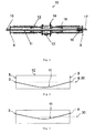
- Fig 1 shows a gas insulated bushing 18 according to the prior art where the present invention could be used.
- the bushing comprises a tubular shell 12 assembled with an intermediate flange 14, also known as wall flange which could be made from welded aluminium, fitted with two insulators, one for each side of the wall flange. Grading of the electrical field is accomplished by internal shields 15 which could be conical aluminium shields and this whole arrangement can be seen as a hollow insulator or tubular shell.
- the insulators can be made of a glass fiber reinforced epoxy in the form of a tube that can be covered by weather sheds made of silicone rubber or other suitable material.
- the tubes are manufactured in one piece and equipped with end flanges 8, 9 at both ends, the end flanges 8, 9 can be glued on and made from cast aluminium.
- the design gives a rigid bushing with excellent mechanical properties.
- the hollow conductor 11, extends through the hollow shell 12 and is fixed at both ends on the end flanges 8, 9 at a fixation point and the conductor is unsupported between the fixation points.
- the bushing can be filled with isolating gas e.g. SF6 (sulfur hexafluoride).
- the isolating gas can be at atmospheric pressure or at an over pressure.
- the bushing is practically rotationally symmetric.
- Fig 2 shows the problem, not in scale, that the present invention tries to solve.
- the fixation of the conductor 11 onto the end flanges 8, 9 is normally rigid so that the fixation point can support bending moment.
- the dashed line 30 is the longitudinal center line of the bushing and the placement for the conductor without static deflection caused by gravity and the mass of the conductor.
- the static deflection at the longitudinal center of the bushing will be different.
- the deflection at the longitudinal center of the bushing will increase dramatically. For bushings longer than 10-20 m the deflection might be so large that the voltage grading shields 15 might not work properly
- Fig 3 shows a prior art solution to overcome the problems described in fig 2 whereby the fixation point of the end flange is shifted up in the vertical direction.
- the shift in fixation point can be on only one end flange or on both end flanges. This shift reduces the static deflection at the longitudinal center of the bushing. If the fixation point is shifted on one side the reduction of static deflection will be half amount that the fixation point was shifted and if both the fixation points are shifted, the reduction of static deflection at longitudinal center will be approximately the same amount that the fixation points were shifted. There is a limit on how much one can shift the fixation point so this solution is limited to medium length bushings.
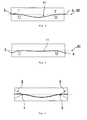
- Fig 4 shows an embodiment of the present invention where the conductor 11 is supported at two points 1, 2 inside the hollow isolator 12 by a supporting body.
- the fixation point and the support points are placed on the longitudinal center line.
- the static deflection at the longitudinal center of the bushing is lowered by the additional support points.
- the fixation point on the end flange have to be strong enough to take up moment that appear in the joint by static deflection of the conductor.
- the fixation point only has to take vertical forces and tension in the longitudinal direction. This allows one to make the joint in the fixation point simpler and weaker which would allow one to save weight on the end flange that may compensate for the weight added by the supporting body.
- Fig 5 shows another embodiment of the present invention similar to the one in fig 4 where the conductor 11 is supported at two points 1, 2 inside the hollow isolator 12 by a supporting body.
- the the fixation point or the support points are not placed on the longitudinal center line.
- the static deflection at the longitudinal center of the bushing is further lowered by the movement of the fixation points over the solution in fig 4 and this creates a moment at the support point.
- Another embodiment, not shown, is that none of the support points and fixation points are placed on the longitudinal center line. The fixation points are placed below the center line and the support points are placed above the centerline in a way to minimize the static deflection of the conductor at the longitudinal center of the bushing.
- Fig 6 shows another embodiment of the present invention where the support body is in a form of a conical body 5, 6 arranged around the conductor.
- the circular end of the support body is fixated on the end flange and the tip of the conical body is the support point.
- the conical body can be a solid body or it can be a hollow body.
- the hollow body can be arranged with openings to allow the gas in the gas inside the bushing to circulate to insulate and cool the conductor.
- Fig 7a shows another embodiment of the present invention where the support body is in a form of a conical body 5, 6 arranged around the conductor where support members are arranged to support the support body against the inner wall of the hollow conductor.
- fig 7b shows an embodiment where the support body is not a conical body but can be any shape and here the support members are arranged to support the support body against the inner wall of the hollow conductor.
- the supporting bodies have advantages for reducing the static deflection from gravity and they also have advantages for reducing dynamic deflection e.g. from earthquakes.
Landscapes
- Engineering & Computer Science (AREA)
- Power Engineering (AREA)
- Insulators (AREA)
- Gas-Insulated Switchgears (AREA)
Abstract
Description
- The present invention relates to the field of high voltage technology, and in particular to gas insulated high voltage bushings.
- Gas insulated High Voltage bushings are used for carrying current at high potential through a plane, often referred to as a grounded plane, where the plane is at a different potential than the current path. Bushings are designed to electrically insulate a high voltage conductor, located inside the bushing, from the grounded plane. The grounded plane can for example be a transformer tank or a wall, such as for example a High Voltage Direct Current (HVDC) valve hall wall. An example of a gas isolated bushing is the GGFL, air to air bushing, by ABB.
- In a gas filled bushing with a free hanging conductor, for example, a wall bushing, the maximum deflection of the conductor in the longitudinal center of the bushing influences the inner diameter of the bushing which affects the outer diameter of the bushing. In order to prevent flashovers, the higher the maximum deflection is the larger the inside diameter of the bushing has to be. Inside of the bushing, different field control shields are arranged to handle the electrical fields. The field control shields will not work as designed if the conductor is not in the radial center or close to the radial center of the bushing. There is thus a need to minimize the deflection of the conductor in very long bushings.
- The static deflection of the conductor is generated by gravity and mass of the conductor itself. The conductor in the bushing is in the form of a tube fixed in both ends. The deflection of a horizontally or near horizontally placed tube is dependent on material constants of the conductor tube (Young's modulus and density), length, wall thickness and diameter of the tube.
- The conductor is dimensioned to conduct a current i.e. for a given current and resistivity, the cross sectional area of the conductor is given. For a conductor of a given outer diameter, the wall thickness will be determined by the cross sectional area of the tube. The length is set by the length of the bushing which is determined by external electric requirements e.g. voltages and flashover distances. For large currents it is in principle only possible to use copper or aluminium or alloys thereof in the conductor. This will determine the material parameter which will then set the maximum stiffness of the material. Almost all material parameters and construction parameters are set by the electric requirements of the bushing.
- To minimize the static deflection of the conductor at the longitudinal center, a number of solutions have been proposed. The tension of the conductor can be increased but this has only a limited effect on the static deflection. Horizontally moving the fixation point, where the conductor is fixed onto the end flange of the bushing, up from the radial center of the bushing will reduce the deflection at the longitudinal center point. The increasing voltages and very high power distributions that today's equipment has to handle make today's bushing very long, 10-20m or even longer. For very long bushings, with large static deflection, the required shift of fixation point to solve the static deflection problem becomes too large to be practical.
- Various aspects of the invention are set out in the accompanying claims.
- The present invention provides a bushing that reduces the static deflection of the conductor at the longitudinal center of the bushing.
- According to the present invention there is provided a high voltage bushing comprising; a tubular shell with an end flange at each end of the shell creating a enclosed volume, a conductor suspended in the enclosed volume, having two ends, one end fixed to one end flange at a first fixation point and the other end fixed to the other end flange at a second fixation point. At least one of the end flanges is provided with a support body extending into the enclosed volume in the longitudinal direction of the bushing, and the body is arranged to support the conductor on at least one support point at a distance from the fixation point on the flange.
- The advantage of this embodiment is that the unsupported length of the conductor is reduced and thereby the static deflection at the longitudinal center of the bushing is reduced. In the present invention the fixation point on the end flange does not have to take up any moment and the fixation arrangement for the conductor can be made simpler and lighter offsetting the additional weight of the supporting body. The support by the body of the conductor may be on one single point or several points or a support surface. The several support points might be distributed along the conductor between the support point and the fixation point. The several points may be both on the lower and upper side of the conductor in the mounted bushing.
- According to an embodiment of the invention, the support body is arranged around the conductor and one end of the body is fixated to the end flange and the other end of the body is provided with an opening for the conductor, where the opening forms the support point. The body might be rotationally symmetric around the conductor and/or the longitudinal center line of the bushing.
- The advantage of this embodiment is that the body is equally supporting independent of if the bushing is rotated and fixing the base of the body on the end flange makes the body stable.
- According to an embodiment of the invention, the support body is made from electrically insulating material such as fiber reinforced polymer or carbon or glass fiber reinforced epoxy.
- The advantage of this embodiment is that the body does not affect the electrical fields.
- According to an embodiment of the invention, the support body is made from metal. The advantage of this embodiment is the mechanical stiffness of metal, such as steel, in some cases makes a better, stiffer support body.
- According to an embodiment of the invention, the support body is conically shaped and arranged around the conductor, the round base of the conically shaped body is fixed onto the end flange and the top of the conically shaped body is provided with an opening for the conductor, where the opening forms the support point.
- The advantage of this embodiment is that the base of the body has a large fixation and support area and the conical form is mechanically good at taking up forces from the support point. In one embodiment the support body comprises several conically shaped bodies stacked on top of each other, all fixed onto the end flange, creating several support points along the conductor between the support point and the fixation point.
- According to an embodiment of the invention, the tubular shell has a longitudinal center line and the body is arranged with the support point at a distance from the center line and so that the support point is positioned above the centerline when the bushing is mounted.
- The advantage of this embodiment is that by arranging the support point above the center line, the static deflection at the longitudinal center of the bushing is minimized.
- According to an embodiment of the invention, the tubular shell has a longitudinal center line and the fixation point is at a distance from the center line and so that the fixation point is positioned below the centerline when the bushing is mounted.
- The advantage of this embodiment is that by arranging the fixation point below the center line, the conductor experiences a moment at the support point that minimizes static deflection at the longitudinal center of the bushing.
- According to an embodiment of the invention, the fixation point and the support point are positioned on opposite sides of the centerline.
- According to an embodiment of the invention, the distance between the support point and the fixation point at the end flange is in the interval 0.3m - 4m.
- According to an embodiment of the invention, the body comprises openings that allow the gas inside the bushing to circulate inside the support body. The advantage of this embodiment is that allows cooling of the part of the conductor that is surrounds by the support body.
- According to an embodiment of the invention, the bushing is filled with SF6 , sulfur hexafluoride, at an over pressure.
- According to an embodiment of the invention, the support body is fixated on the end flange and comprises one or more support members, supporting the support body on the inner wall of the tubular shell.
- According to an embodiment of the invention, the other of the end flanges is provided with a support body extending into the enclosed volume in the longitudinal direction of the bushing, and the body is arranged to support the conductor at a second support point at a distance from the fixation point on the flange.
- Although various aspects of the invention are set out in the accompanying independent claims, other aspects of the invention include the combination of any features presented in the described embodiments and/or in the accompanying claims, and not solely the combinations explicitly set out in the accompanying claims.
- The drawings constitute a part of this specification and include exemplary embodiments to the invention, which may be embodied in various forms.
-
Fig 1 shows a gas insulated bushing where the present invention could be used. -
Fig 2 shows the problem that the present invention tries to solve. -
Fig 3 shows a prior art solution. -
Fig 4 shows an embodiment of the present invention. -
Fig 5 shows another embodiment of the present invention. -
Fig 6 shows another embodiment of the present invention. -
Fig 7a-b shows another embodiment of the support body. -
Fig 1 shows a gas insulatedbushing 18 according to the prior art where the present invention could be used. The bushing comprises atubular shell 12 assembled with anintermediate flange 14, also known as wall flange which could be made from welded aluminium, fitted with two insulators, one for each side of the wall flange. Grading of the electrical field is accomplished byinternal shields 15 which could be conical aluminium shields and this whole arrangement can be seen as a hollow insulator or tubular shell. The insulators can be made of a glass fiber reinforced epoxy in the form of a tube that can be covered by weather sheds made of silicone rubber or other suitable material. The tubes are manufactured in one piece and equipped withend flanges end flanges hollow conductor 11, extends through thehollow shell 12 and is fixed at both ends on theend flanges -
Fig 2 shows the problem, not in scale, that the present invention tries to solve. The fixation of theconductor 11 onto theend flanges - The dashed
line 30 is the longitudinal center line of the bushing and the placement for the conductor without static deflection caused by gravity and the mass of the conductor. Dependent on the length of the bushing and thereby the unsupported length of the conductor, the static deflection at the longitudinal center of the bushing will be different. As the length of the bushing increases, the deflection at the longitudinal center of the bushing will increase dramatically. For bushings longer than 10-20 m the deflection might be so large that the voltage grading shields 15 might not work properly -
Fig 3 shows a prior art solution to overcome the problems described infig 2 whereby the fixation point of the end flange is shifted up in the vertical direction. The shift in fixation point can be on only one end flange or on both end flanges. This shift reduces the static deflection at the longitudinal center of the bushing. If the fixation point is shifted on one side the reduction of static deflection will be half amount that the fixation point was shifted and if both the fixation points are shifted, the reduction of static deflection at longitudinal center will be approximately the same amount that the fixation points were shifted. There is a limit on how much one can shift the fixation point so this solution is limited to medium length bushings. - Other solutions known in the prior art is to increase the tension in the conductor or change the construction of the conductor e.g. make the diameter of the conductor larger. All these solutions might not be sufficient for the longest bushings for the highest voltages.
-
Fig 4 shows an embodiment of the present invention where theconductor 11 is supported at twopoints hollow isolator 12 by a supporting body. The fixation point and the support points are placed on the longitudinal center line. The static deflection at the longitudinal center of the bushing is lowered by the additional support points. In the prior art solutions, the fixation point on the end flange have to be strong enough to take up moment that appear in the joint by static deflection of the conductor. In the present invention the fixation point only has to take vertical forces and tension in the longitudinal direction. This allows one to make the joint in the fixation point simpler and weaker which would allow one to save weight on the end flange that may compensate for the weight added by the supporting body. -
Fig 5 shows another embodiment of the present invention similar to the one infig 4 where theconductor 11 is supported at twopoints hollow isolator 12 by a supporting body. The the fixation point or the support points are not placed on the longitudinal center line. Infig 5 , the static deflection at the longitudinal center of the bushing is further lowered by the movement of the fixation points over the solution infig 4 and this creates a moment at the support point. Another embodiment, not shown, is that none of the support points and fixation points are placed on the longitudinal center line. The fixation points are placed below the center line and the support points are placed above the centerline in a way to minimize the static deflection of the conductor at the longitudinal center of the bushing. -
Fig 6 shows another embodiment of the present invention where the support body is in a form of aconical body 5, 6 arranged around the conductor. The circular end of the support body is fixated on the end flange and the tip of the conical body is the support point. The conical body can be a solid body or it can be a hollow body. The hollow body can be arranged with openings to allow the gas in the gas inside the bushing to circulate to insulate and cool the conductor. -
Fig 7a shows another embodiment of the present invention where the support body is in a form of aconical body 5, 6 arranged around the conductor where support members are arranged to support the support body against the inner wall of the hollow conductor. Infig 7b shows an embodiment where the support body is not a conical body but can be any shape and here the support members are arranged to support the support body against the inner wall of the hollow conductor. - The supporting bodies have advantages for reducing the static deflection from gravity and they also have advantages for reducing dynamic deflection e.g. from earthquakes.
Claims (15)
- A high voltage gas isolated bushing (18) comprising;- a tubular shell (12) with an end flange (8, 9) at each end of the shell creating a enclosed volume,- a conductor (11) suspended in the enclosed volume, having two ends, one end fixed to one end flange at a first fixation point and the other end fixed to the other end flange at a second fixation point and,characterized in that
at least one of the end flanges (8, 9) is provided with a support body (5, 6) extending into the enclosed volume in the longitudinal direction of the bushing, and the body is arranged to support the conductor on at least one support point (1, 2) at a distance from the fixation point on the flange. - A high voltage bushing according to claim 1, wherein the support body (5, 6) is arranged arround the conductor and one end of the body is fixated to the end flange (8, 9) and the other end is provided with an opening for the conductor, where the opening forms the at least one support point (1, 2).
- A high voltage bushing according to claims 1-2, wherein the support body (5, 6) is made from electrically insulating material.
- A high voltage bushing according to claim 1-3, wherein the support body (5, 6) is made from fiber reinforced polymer
- A high voltage bushing according to claim 1-4, wherein the support body (5, 6) is made from carbon or glass fiber reinforced epoxy.
- A high voltage bushing according to claims 1-2, wherein the support body is made from metal.
- A high voltage bushing according to claim 1-6, wherein the support body (5, 6) is conically shaped and arranged around the conductor, the round base of the conically shaped body is fixed onto the end flange (8, 9) and the conically shaped body is provided with an opening for the conductor, where the opening forms the at least one support point.
- A high voltage bushing according to claim 1-7, wherein the tubular shell has a longitudinal center line (30) and the body is arranged with the support point at a distance from the center line and so that the support point (1, 2) is positioned above the centerline when the bushing is mounted.
- A high voltage bushing according to claim 1-7, wherein the tubular shell has a longitudinal center line (30) and the fixation point (3, 4) is at a distance from the center line and so that the fixation point is positioned below the centerline when the bushing is mounted.
- A high voltage bushing according to claim 8 and 9, wherein the fixation point (3, 4) and the support point (1, 2) are positioned on opposite sides of the centerline.
- A high voltage bushing according to claim 1-10, wherein the distance between the support point (1, 2) and the end flange (8, 9) is in the interval 0.3 - 4m.
- A high voltage bushing according to claim 1-11, wherein the support body (5, 6) comprises openings that allows the gas inside the bushing to circulate inside the support body.
- A high voltage bushing according to claim 1-12, wherein the bushing is filled with SF6 at an over pressure.
- A high voltage bushing according to claim 1-13, wherein the support body (5, 6) is fixated on the end flange (8, 9) and comprises one or more support members (7), supporting the support body on the inner wall of the tubular shell.
- A high voltage bushing according to claim 1-14, wherein both end flanges (8, 9) are provided with a support bodies (5, 6) extending into the enclosed volume in the longitudinal direction of the bushing, and the support body is arranged to support the conductor at support points (1, 2) at a distance from the fixation points on the flanges.
Priority Applications (7)
| Application Number | Priority Date | Filing Date | Title |
|---|---|---|---|
| EP11158377.9A EP2500914B1 (en) | 2011-03-16 | 2011-03-16 | High voltage bushing with support for the conductor |
| KR1020137027224A KR101980923B1 (en) | 2011-03-16 | 2012-01-31 | High voltage bushing with support for the conductor |
| CN201280013369.5A CN103443875B (en) | 2011-03-16 | 2012-01-31 | There is the high voltage bushing of the support for conductor |
| PCT/EP2012/051511 WO2012123163A1 (en) | 2011-03-16 | 2012-01-31 | High voltage bushing with support for the conductor |
| US14/004,830 US8847077B2 (en) | 2011-03-16 | 2012-01-31 | High voltage bushing with support for the conductor |
| BR112013023350-8A BR112013023350B1 (en) | 2011-03-16 | 2012-01-31 | Gas insulated high voltage bushing |
| ZA2013/06584A ZA201306584B (en) | 2011-03-16 | 2013-09-02 | High voltage bushing with support for the conductor |
Applications Claiming Priority (1)
| Application Number | Priority Date | Filing Date | Title |
|---|---|---|---|
| EP11158377.9A EP2500914B1 (en) | 2011-03-16 | 2011-03-16 | High voltage bushing with support for the conductor |
Publications (2)
| Publication Number | Publication Date |
|---|---|
| EP2500914A1 true EP2500914A1 (en) | 2012-09-19 |
| EP2500914B1 EP2500914B1 (en) | 2014-03-05 |
Family
ID=44314921
Family Applications (1)
| Application Number | Title | Priority Date | Filing Date |
|---|---|---|---|
| EP11158377.9A Active EP2500914B1 (en) | 2011-03-16 | 2011-03-16 | High voltage bushing with support for the conductor |
Country Status (7)
| Country | Link |
|---|---|
| US (1) | US8847077B2 (en) |
| EP (1) | EP2500914B1 (en) |
| KR (1) | KR101980923B1 (en) |
| CN (1) | CN103443875B (en) |
| BR (1) | BR112013023350B1 (en) |
| WO (1) | WO2012123163A1 (en) |
| ZA (1) | ZA201306584B (en) |
Families Citing this family (2)
| Publication number | Priority date | Publication date | Assignee | Title |
|---|---|---|---|---|
| WO2013104412A1 (en) * | 2012-01-09 | 2013-07-18 | Alstom Technology Ltd | Plug and socket pure gas insulated wall bushing for hvdc and uhv |
| CN108257741B (en) * | 2018-03-27 | 2021-04-23 | 江苏神马电力股份有限公司 | Post insulator and insulating post |
Citations (5)
| Publication number | Priority date | Publication date | Assignee | Title |
|---|---|---|---|---|
| US4523052A (en) * | 1982-05-19 | 1985-06-11 | Tokyo Shibaura Denki Kabushiki Kaisha | Gas-insulated bushing |
| JP2000331545A (en) * | 1999-05-24 | 2000-11-30 | Sumitomo Electric Ind Ltd | Compressed gas insulated transmission line in pipe line |
| US20100018752A1 (en) * | 2006-08-31 | 2010-01-28 | Abb Research Ltd. | High voltage bushing |
| WO2010097887A1 (en) * | 2009-02-24 | 2010-09-02 | 三菱電機株式会社 | Gas bushing |
| EP2264719A1 (en) * | 2009-06-18 | 2010-12-22 | ABB Technology Ltd | High voltage device |
Family Cites Families (12)
| Publication number | Priority date | Publication date | Assignee | Title |
|---|---|---|---|---|
| DE3920355A1 (en) * | 1989-06-19 | 1990-12-20 | Siemens Ag | INSULATING HOUSING PART WITH A LEAD |
| US5466891A (en) * | 1994-04-08 | 1995-11-14 | Abb Power T&D Company Inc. | Conical composite SF6 high voltage bushing with floating shield |
| US6218627B1 (en) * | 1998-02-04 | 2001-04-17 | Hitachi, Ltd. | Bushing |
| JP2002157932A (en) * | 2000-11-21 | 2002-05-31 | Furukawa Electric Co Ltd:The | Organic composite insulator tube and method of manufacturing the same |
| CN1929041A (en) * | 2006-08-17 | 2007-03-14 | 江苏东源电器集团股份有限公司 | 35KV O-shaped bus wall bushing |
| CN101136269B (en) * | 2006-08-31 | 2013-03-27 | Abb研究有限公司 | High voltage bushing |
| FR2919955B1 (en) * | 2007-08-07 | 2009-10-30 | Areva T & D Sa | DEVICE FOR CONTROLLING A HIGH ELECTRIC FIELD IN AN INSULATING SYNTHETIC MATERIAL, IN PARTICULAR FOR A CURRENT THROUGH A WALL THROUGH A WALL |
| EP2039496A1 (en) * | 2007-09-20 | 2009-03-25 | ABB Research Ltd. | A method of producing a rubber product |
| EP2048673B1 (en) * | 2007-10-12 | 2014-05-14 | ABB Research Ltd. | A device for electric connection, a method for producing such a device, and an electric power installation provided therewith |
| EP2063512A1 (en) * | 2007-11-21 | 2009-05-27 | Abb Research Ltd. | A method of producing an electric power device, and an electric power device |
| CN101740177A (en) * | 2008-11-12 | 2010-06-16 | 戴海永 | Composite insulated sleeve |
| CN101807459B (en) * | 2010-03-10 | 2012-05-23 | 中国电力科学研究院 | An ultra-high voltage gas-insulated porcelain bushing |
-
2011
- 2011-03-16 EP EP11158377.9A patent/EP2500914B1/en active Active
-
2012
- 2012-01-31 CN CN201280013369.5A patent/CN103443875B/en active Active
- 2012-01-31 BR BR112013023350-8A patent/BR112013023350B1/en active IP Right Grant
- 2012-01-31 KR KR1020137027224A patent/KR101980923B1/en active Active
- 2012-01-31 US US14/004,830 patent/US8847077B2/en active Active
- 2012-01-31 WO PCT/EP2012/051511 patent/WO2012123163A1/en not_active Ceased
-
2013
- 2013-09-02 ZA ZA2013/06584A patent/ZA201306584B/en unknown
Patent Citations (5)
| Publication number | Priority date | Publication date | Assignee | Title |
|---|---|---|---|---|
| US4523052A (en) * | 1982-05-19 | 1985-06-11 | Tokyo Shibaura Denki Kabushiki Kaisha | Gas-insulated bushing |
| JP2000331545A (en) * | 1999-05-24 | 2000-11-30 | Sumitomo Electric Ind Ltd | Compressed gas insulated transmission line in pipe line |
| US20100018752A1 (en) * | 2006-08-31 | 2010-01-28 | Abb Research Ltd. | High voltage bushing |
| WO2010097887A1 (en) * | 2009-02-24 | 2010-09-02 | 三菱電機株式会社 | Gas bushing |
| EP2264719A1 (en) * | 2009-06-18 | 2010-12-22 | ABB Technology Ltd | High voltage device |
Non-Patent Citations (1)
| Title |
|---|
| ABB COMPONENTS: "Gas insulated wall bushing, type GGFL, Installation and maintenance guide", vol. 2770 501-8 en, Rev. 3, 7 December 2010 (2010-12-07), XP002655965, Retrieved from the Internet <URL:http://www05.abb.com/global/scot/scot252.nsf/veritydisplay/65148ddb16a0528cc12577f20038764d/$file/2770%20501-8%20en%20rev%203.pdf> [retrieved on 20110803] * |
Also Published As
| Publication number | Publication date |
|---|---|
| BR112013023350A2 (en) | 2016-12-06 |
| KR20140031216A (en) | 2014-03-12 |
| BR112013023350B1 (en) | 2022-02-22 |
| WO2012123163A1 (en) | 2012-09-20 |
| EP2500914B1 (en) | 2014-03-05 |
| US20140000936A1 (en) | 2014-01-02 |
| CN103443875B (en) | 2016-02-17 |
| KR101980923B1 (en) | 2019-05-21 |
| US8847077B2 (en) | 2014-09-30 |
| ZA201306584B (en) | 2014-05-28 |
| CN103443875A (en) | 2013-12-11 |
Similar Documents
| Publication | Publication Date | Title |
|---|---|---|
| CN103026564B (en) | Gas Insulated Electrical Equipment | |
| US8389876B2 (en) | High voltage bushing | |
| US9218900B2 (en) | High voltage bushing with reinforced conductor | |
| US8748757B2 (en) | Temperature compensated bushing design | |
| JP2023543238A (en) | High voltage equipment and methods for increasing dielectric strength in high voltage equipment | |
| EP2500914B1 (en) | High voltage bushing with support for the conductor | |
| US20140034464A1 (en) | Tap Changer | |
| US8088996B2 (en) | High voltage DC bushing and device comprising such high voltage bushing | |
| KR101034878B1 (en) | High voltage bushings with improved field relaxation and insulation | |
| EP1103988A2 (en) | SEmi-capacitance graded bushing insulator of the type with insulating gas filling, such as SF6 | |
| EP2458701A1 (en) | High voltage bushing | |
| EP3905464A1 (en) | Dry-type high voltage cable termination | |
| WO2017108141A1 (en) | Support structure and layout for a hvdc disconnector | |
| JP2012075266A (en) | Polymer bushing insulator | |
| CN116438612A (en) | Coated conductors in high voltage equipment and method for increasing dielectric strength | |
| RU61463U1 (en) | PASS-INSULATOR WITH SILICONE INSULATING LAYER | |
| JPH0898341A (en) | Switch gear | |
| KR102569088B1 (en) | Gas insulation switchgear | |
| JPH06231636A (en) | Gas insulating bushing | |
| GB2115988A (en) | Insulating bushing | |
| JP6139841B2 (en) | Tank type vacuum circuit breaker | |
| JPH07255117A (en) | Spacer for transmission/distribution line | |
| JP2021100059A (en) | Stationary induction device | |
| EP1074999A1 (en) | Hollow core composite insulator | |
| JPH0935559A (en) | Gas insulated bushing |
Legal Events
| Date | Code | Title | Description |
|---|---|---|---|
| PUAI | Public reference made under article 153(3) epc to a published international application that has entered the european phase |
Free format text: ORIGINAL CODE: 0009012 |
|
| AK | Designated contracting states |
Kind code of ref document: A1 Designated state(s): AL AT BE BG CH CY CZ DE DK EE ES FI FR GB GR HR HU IE IS IT LI LT LU LV MC MK MT NL NO PL PT RO RS SE SI SK SM TR |
|
| AX | Request for extension of the european patent |
Extension state: BA ME |
|
| 17P | Request for examination filed |
Effective date: 20130319 |
|
| RIC1 | Information provided on ipc code assigned before grant |
Ipc: H01B 17/42 20060101ALN20130927BHEP Ipc: H01B 17/36 20060101ALN20130927BHEP Ipc: H01B 17/26 20060101AFI20130927BHEP |
|
| GRAP | Despatch of communication of intention to grant a patent |
Free format text: ORIGINAL CODE: EPIDOSNIGR1 |
|
| INTG | Intention to grant announced |
Effective date: 20131108 |
|
| GRAS | Grant fee paid |
Free format text: ORIGINAL CODE: EPIDOSNIGR3 |
|
| GRAA | (expected) grant |
Free format text: ORIGINAL CODE: 0009210 |
|
| AK | Designated contracting states |
Kind code of ref document: B1 Designated state(s): AL AT BE BG CH CY CZ DE DK EE ES FI FR GB GR HR HU IE IS IT LI LT LU LV MC MK MT NL NO PL PT RO RS SE SI SK SM TR |
|
| REG | Reference to a national code |
Ref country code: GB Ref legal event code: FG4D |
|
| REG | Reference to a national code |
Ref country code: CH Ref legal event code: EP |
|
| REG | Reference to a national code |
Ref country code: AT Ref legal event code: REF Ref document number: 655363 Country of ref document: AT Kind code of ref document: T Effective date: 20140315 |
|
| REG | Reference to a national code |
Ref country code: IE Ref legal event code: FG4D |
|
| REG | Reference to a national code |
Ref country code: DE Ref legal event code: R096 Ref document number: 602011005147 Country of ref document: DE Effective date: 20140417 |
|
| REG | Reference to a national code |
Ref country code: AT Ref legal event code: MK05 Ref document number: 655363 Country of ref document: AT Kind code of ref document: T Effective date: 20140305 |
|
| REG | Reference to a national code |
Ref country code: NL Ref legal event code: VDEP Effective date: 20140305 |
|
| PG25 | Lapsed in a contracting state [announced via postgrant information from national office to epo] |
Ref country code: NO Free format text: LAPSE BECAUSE OF FAILURE TO SUBMIT A TRANSLATION OF THE DESCRIPTION OR TO PAY THE FEE WITHIN THE PRESCRIBED TIME-LIMIT Effective date: 20140605 Ref country code: LT Free format text: LAPSE BECAUSE OF FAILURE TO SUBMIT A TRANSLATION OF THE DESCRIPTION OR TO PAY THE FEE WITHIN THE PRESCRIBED TIME-LIMIT Effective date: 20140305 |
|
| REG | Reference to a national code |
Ref country code: LT Ref legal event code: MG4D |
|
| PG25 | Lapsed in a contracting state [announced via postgrant information from national office to epo] |
Ref country code: CY Free format text: LAPSE BECAUSE OF FAILURE TO SUBMIT A TRANSLATION OF THE DESCRIPTION OR TO PAY THE FEE WITHIN THE PRESCRIBED TIME-LIMIT Effective date: 20140305 Ref country code: SE Free format text: LAPSE BECAUSE OF FAILURE TO SUBMIT A TRANSLATION OF THE DESCRIPTION OR TO PAY THE FEE WITHIN THE PRESCRIBED TIME-LIMIT Effective date: 20140305 Ref country code: AT Free format text: LAPSE BECAUSE OF FAILURE TO SUBMIT A TRANSLATION OF THE DESCRIPTION OR TO PAY THE FEE WITHIN THE PRESCRIBED TIME-LIMIT Effective date: 20140305 Ref country code: FI Free format text: LAPSE BECAUSE OF FAILURE TO SUBMIT A TRANSLATION OF THE DESCRIPTION OR TO PAY THE FEE WITHIN THE PRESCRIBED TIME-LIMIT Effective date: 20140305 |
|
| PG25 | Lapsed in a contracting state [announced via postgrant information from national office to epo] |
Ref country code: HR Free format text: LAPSE BECAUSE OF FAILURE TO SUBMIT A TRANSLATION OF THE DESCRIPTION OR TO PAY THE FEE WITHIN THE PRESCRIBED TIME-LIMIT Effective date: 20140305 Ref country code: RS Free format text: LAPSE BECAUSE OF FAILURE TO SUBMIT A TRANSLATION OF THE DESCRIPTION OR TO PAY THE FEE WITHIN THE PRESCRIBED TIME-LIMIT Effective date: 20140305 Ref country code: LV Free format text: LAPSE BECAUSE OF FAILURE TO SUBMIT A TRANSLATION OF THE DESCRIPTION OR TO PAY THE FEE WITHIN THE PRESCRIBED TIME-LIMIT Effective date: 20140305 |
|
| PG25 | Lapsed in a contracting state [announced via postgrant information from national office to epo] |
Ref country code: BE Free format text: LAPSE BECAUSE OF FAILURE TO SUBMIT A TRANSLATION OF THE DESCRIPTION OR TO PAY THE FEE WITHIN THE PRESCRIBED TIME-LIMIT Effective date: 20140305 Ref country code: CZ Free format text: LAPSE BECAUSE OF FAILURE TO SUBMIT A TRANSLATION OF THE DESCRIPTION OR TO PAY THE FEE WITHIN THE PRESCRIBED TIME-LIMIT Effective date: 20140305 Ref country code: EE Free format text: LAPSE BECAUSE OF FAILURE TO SUBMIT A TRANSLATION OF THE DESCRIPTION OR TO PAY THE FEE WITHIN THE PRESCRIBED TIME-LIMIT Effective date: 20140305 Ref country code: IS Free format text: LAPSE BECAUSE OF FAILURE TO SUBMIT A TRANSLATION OF THE DESCRIPTION OR TO PAY THE FEE WITHIN THE PRESCRIBED TIME-LIMIT Effective date: 20140705 Ref country code: BG Free format text: LAPSE BECAUSE OF FAILURE TO SUBMIT A TRANSLATION OF THE DESCRIPTION OR TO PAY THE FEE WITHIN THE PRESCRIBED TIME-LIMIT Effective date: 20140605 Ref country code: RO Free format text: LAPSE BECAUSE OF FAILURE TO SUBMIT A TRANSLATION OF THE DESCRIPTION OR TO PAY THE FEE WITHIN THE PRESCRIBED TIME-LIMIT Effective date: 20140305 Ref country code: NL Free format text: LAPSE BECAUSE OF FAILURE TO SUBMIT A TRANSLATION OF THE DESCRIPTION OR TO PAY THE FEE WITHIN THE PRESCRIBED TIME-LIMIT Effective date: 20140305 |
|
| REG | Reference to a national code |
Ref country code: CH Ref legal event code: PL |
|
| PG25 | Lapsed in a contracting state [announced via postgrant information from national office to epo] |
Ref country code: ES Free format text: LAPSE BECAUSE OF FAILURE TO SUBMIT A TRANSLATION OF THE DESCRIPTION OR TO PAY THE FEE WITHIN THE PRESCRIBED TIME-LIMIT Effective date: 20140305 Ref country code: PL Free format text: LAPSE BECAUSE OF FAILURE TO SUBMIT A TRANSLATION OF THE DESCRIPTION OR TO PAY THE FEE WITHIN THE PRESCRIBED TIME-LIMIT Effective date: 20140305 Ref country code: SK Free format text: LAPSE BECAUSE OF FAILURE TO SUBMIT A TRANSLATION OF THE DESCRIPTION OR TO PAY THE FEE WITHIN THE PRESCRIBED TIME-LIMIT Effective date: 20140305 |
|
| REG | Reference to a national code |
Ref country code: DE Ref legal event code: R097 Ref document number: 602011005147 Country of ref document: DE |
|
| PG25 | Lapsed in a contracting state [announced via postgrant information from national office to epo] |
Ref country code: PT Free format text: LAPSE BECAUSE OF FAILURE TO SUBMIT A TRANSLATION OF THE DESCRIPTION OR TO PAY THE FEE WITHIN THE PRESCRIBED TIME-LIMIT Effective date: 20140707 |
|
| REG | Reference to a national code |
Ref country code: IE Ref legal event code: MM4A |
|
| PLBE | No opposition filed within time limit |
Free format text: ORIGINAL CODE: 0009261 |
|
| STAA | Information on the status of an ep patent application or granted ep patent |
Free format text: STATUS: NO OPPOSITION FILED WITHIN TIME LIMIT |
|
| PG25 | Lapsed in a contracting state [announced via postgrant information from national office to epo] |
Ref country code: MC Free format text: LAPSE BECAUSE OF FAILURE TO SUBMIT A TRANSLATION OF THE DESCRIPTION OR TO PAY THE FEE WITHIN THE PRESCRIBED TIME-LIMIT Effective date: 20140305 Ref country code: DK Free format text: LAPSE BECAUSE OF FAILURE TO SUBMIT A TRANSLATION OF THE DESCRIPTION OR TO PAY THE FEE WITHIN THE PRESCRIBED TIME-LIMIT Effective date: 20140305 Ref country code: IE Free format text: LAPSE BECAUSE OF NON-PAYMENT OF DUE FEES Effective date: 20140316 Ref country code: CH Free format text: LAPSE BECAUSE OF NON-PAYMENT OF DUE FEES Effective date: 20140331 Ref country code: LI Free format text: LAPSE BECAUSE OF NON-PAYMENT OF DUE FEES Effective date: 20140331 |
|
| 26N | No opposition filed |
Effective date: 20141208 |
|
| REG | Reference to a national code |
Ref country code: DE Ref legal event code: R097 Ref document number: 602011005147 Country of ref document: DE Effective date: 20141208 |
|
| PG25 | Lapsed in a contracting state [announced via postgrant information from national office to epo] |
Ref country code: SI Free format text: LAPSE BECAUSE OF FAILURE TO SUBMIT A TRANSLATION OF THE DESCRIPTION OR TO PAY THE FEE WITHIN THE PRESCRIBED TIME-LIMIT Effective date: 20140305 |
|
| GBPC | Gb: european patent ceased through non-payment of renewal fee |
Effective date: 20150316 |
|
| PG25 | Lapsed in a contracting state [announced via postgrant information from national office to epo] |
Ref country code: GB Free format text: LAPSE BECAUSE OF NON-PAYMENT OF DUE FEES Effective date: 20150316 |
|
| PG25 | Lapsed in a contracting state [announced via postgrant information from national office to epo] |
Ref country code: MT Free format text: LAPSE BECAUSE OF FAILURE TO SUBMIT A TRANSLATION OF THE DESCRIPTION OR TO PAY THE FEE WITHIN THE PRESCRIBED TIME-LIMIT Effective date: 20140305 |
|
| REG | Reference to a national code |
Ref country code: FR Ref legal event code: PLFP Year of fee payment: 6 |
|
| PG25 | Lapsed in a contracting state [announced via postgrant information from national office to epo] |
Ref country code: SM Free format text: LAPSE BECAUSE OF FAILURE TO SUBMIT A TRANSLATION OF THE DESCRIPTION OR TO PAY THE FEE WITHIN THE PRESCRIBED TIME-LIMIT Effective date: 20140305 |
|
| PG25 | Lapsed in a contracting state [announced via postgrant information from national office to epo] |
Ref country code: GR Free format text: LAPSE BECAUSE OF FAILURE TO SUBMIT A TRANSLATION OF THE DESCRIPTION OR TO PAY THE FEE WITHIN THE PRESCRIBED TIME-LIMIT Effective date: 20140606 |
|
| PG25 | Lapsed in a contracting state [announced via postgrant information from national office to epo] |
Ref country code: LU Free format text: LAPSE BECAUSE OF NON-PAYMENT OF DUE FEES Effective date: 20140316 Ref country code: HU Free format text: LAPSE BECAUSE OF FAILURE TO SUBMIT A TRANSLATION OF THE DESCRIPTION OR TO PAY THE FEE WITHIN THE PRESCRIBED TIME-LIMIT; INVALID AB INITIO Effective date: 20110316 Ref country code: TR Free format text: LAPSE BECAUSE OF FAILURE TO SUBMIT A TRANSLATION OF THE DESCRIPTION OR TO PAY THE FEE WITHIN THE PRESCRIBED TIME-LIMIT Effective date: 20140305 |
|
| REG | Reference to a national code |
Ref country code: FR Ref legal event code: PLFP Year of fee payment: 7 |
|
| REG | Reference to a national code |
Ref country code: DE Ref legal event code: R081 Ref document number: 602011005147 Country of ref document: DE Owner name: HITACHI ENERGY SWITZERLAND AG, CH Free format text: FORMER OWNER: ABB TECHNOLOGY LTD., ZUERICH, CH Ref country code: DE Ref legal event code: R081 Ref document number: 602011005147 Country of ref document: DE Owner name: ABB SCHWEIZ AG, CH Free format text: FORMER OWNER: ABB TECHNOLOGY LTD., ZUERICH, CH Ref country code: DE Ref legal event code: R081 Ref document number: 602011005147 Country of ref document: DE Owner name: ABB POWER GRIDS SWITZERLAND AG, CH Free format text: FORMER OWNER: ABB TECHNOLOGY LTD., ZUERICH, CH |
|
| REG | Reference to a national code |
Ref country code: FR Ref legal event code: PLFP Year of fee payment: 8 |
|
| PG25 | Lapsed in a contracting state [announced via postgrant information from national office to epo] |
Ref country code: MK Free format text: LAPSE BECAUSE OF FAILURE TO SUBMIT A TRANSLATION OF THE DESCRIPTION OR TO PAY THE FEE WITHIN THE PRESCRIBED TIME-LIMIT Effective date: 20140305 |
|
| REG | Reference to a national code |
Ref country code: FR Ref legal event code: TP Owner name: ABB SCHWEIZ AG, CH Effective date: 20180912 |
|
| PG25 | Lapsed in a contracting state [announced via postgrant information from national office to epo] |
Ref country code: AL Free format text: LAPSE BECAUSE OF FAILURE TO SUBMIT A TRANSLATION OF THE DESCRIPTION OR TO PAY THE FEE WITHIN THE PRESCRIBED TIME-LIMIT Effective date: 20140305 |
|
| REG | Reference to a national code |
Ref country code: DE Ref legal event code: R081 Ref document number: 602011005147 Country of ref document: DE Owner name: HITACHI ENERGY SWITZERLAND AG, CH Free format text: FORMER OWNER: ABB SCHWEIZ AG, BADEN, CH Ref country code: DE Ref legal event code: R081 Ref document number: 602011005147 Country of ref document: DE Owner name: HITACHI ENERGY LTD, CH Free format text: FORMER OWNER: ABB SCHWEIZ AG, BADEN, CH Ref country code: DE Ref legal event code: R081 Ref document number: 602011005147 Country of ref document: DE Owner name: ABB POWER GRIDS SWITZERLAND AG, CH Free format text: FORMER OWNER: ABB SCHWEIZ AG, BADEN, CH |
|
| REG | Reference to a national code |
Ref country code: DE Ref legal event code: R081 Ref document number: 602011005147 Country of ref document: DE Owner name: HITACHI ENERGY SWITZERLAND AG, CH Free format text: FORMER OWNER: ABB POWER GRIDS SWITZERLAND AG, BADEN, CH Ref country code: DE Ref legal event code: R081 Ref document number: 602011005147 Country of ref document: DE Owner name: HITACHI ENERGY LTD, CH Free format text: FORMER OWNER: ABB POWER GRIDS SWITZERLAND AG, BADEN, CH |
|
| P01 | Opt-out of the competence of the unified patent court (upc) registered |
Effective date: 20230527 |
|
| REG | Reference to a national code |
Ref country code: DE Ref legal event code: R082 Ref document number: 602011005147 Country of ref document: DE Representative=s name: DENNEMEYER & ASSOCIATES RECHTSANWALTSGESELLSCH, DE Ref country code: DE Ref legal event code: R082 Ref document number: 602011005147 Country of ref document: DE Representative=s name: DENNEMEYER & ASSOCIATES S.A., DE Ref country code: DE Ref legal event code: R081 Ref document number: 602011005147 Country of ref document: DE Owner name: HITACHI ENERGY LTD, CH Free format text: FORMER OWNER: HITACHI ENERGY SWITZERLAND AG, BADEN, CH |
|
| REG | Reference to a national code |
Ref country code: DE Ref legal event code: R082 Ref document number: 602011005147 Country of ref document: DE Representative=s name: DENNEMEYER & ASSOCIATES RECHTSANWALTSGESELLSCH, DE |
|
| PGFP | Annual fee paid to national office [announced via postgrant information from national office to epo] |
Ref country code: DE Payment date: 20260319 Year of fee payment: 16 |
|
| PGFP | Annual fee paid to national office [announced via postgrant information from national office to epo] |
Ref country code: IT Payment date: 20260324 Year of fee payment: 16 |
|
| PGFP | Annual fee paid to national office [announced via postgrant information from national office to epo] |
Ref country code: FR Payment date: 20260320 Year of fee payment: 16 |