EP2500900B1 - Vorrichtung, Verfahren und Computerprogramm zur Ableitung eines Mehrkanal-Audiosignals aus einem Audiosignal - Google Patents
Vorrichtung, Verfahren und Computerprogramm zur Ableitung eines Mehrkanal-Audiosignals aus einem Audiosignal Download PDFInfo
- Publication number
- EP2500900B1 EP2500900B1 EP12168768.5A EP12168768A EP2500900B1 EP 2500900 B1 EP2500900 B1 EP 2500900B1 EP 12168768 A EP12168768 A EP 12168768A EP 2500900 B1 EP2500900 B1 EP 2500900B1
- Authority
- EP
- European Patent Office
- Prior art keywords
- signal
- representation
- audio signal
- ambient
- loudspeaker
- Prior art date
- Legal status (The legal status is an assumption and is not a legal conclusion. Google has not performed a legal analysis and makes no representation as to the accuracy of the status listed.)
- Active
Links
Images


Classifications
-
- H—ELECTRICITY
- H04—ELECTRIC COMMUNICATION TECHNIQUE
- H04S—STEREOPHONIC SYSTEMS
- H04S5/00—Pseudo-stereo systems, e.g. in which additional channel signals are derived from monophonic signals by means of phase shifting, time delay or reverberation
- H04S5/005—Pseudo-stereo systems, e.g. in which additional channel signals are derived from monophonic signals by means of phase shifting, time delay or reverberation of the pseudo five- or more-channel type, e.g. virtual surround
-
- G—PHYSICS
- G10—MUSICAL INSTRUMENTS; ACOUSTICS
- G10L—SPEECH ANALYSIS TECHNIQUES OR SPEECH SYNTHESIS; SPEECH RECOGNITION; SPEECH OR VOICE PROCESSING TECHNIQUES; SPEECH OR AUDIO CODING OR DECODING
- G10L19/00—Speech or audio signals analysis-synthesis techniques for redundancy reduction, e.g. in vocoders; Coding or decoding of speech or audio signals, using source filter models or psychoacoustic analysis
- G10L19/008—Multichannel audio signal coding or decoding using interchannel correlation to reduce redundancy, e.g. joint-stereo, intensity-coding or matrixing
-
- G—PHYSICS
- G10—MUSICAL INSTRUMENTS; ACOUSTICS
- G10L—SPEECH ANALYSIS TECHNIQUES OR SPEECH SYNTHESIS; SPEECH RECOGNITION; SPEECH OR VOICE PROCESSING TECHNIQUES; SPEECH OR AUDIO CODING OR DECODING
- G10L19/00—Speech or audio signals analysis-synthesis techniques for redundancy reduction, e.g. in vocoders; Coding or decoding of speech or audio signals, using source filter models or psychoacoustic analysis
- G10L19/02—Speech or audio signals analysis-synthesis techniques for redundancy reduction, e.g. in vocoders; Coding or decoding of speech or audio signals, using source filter models or psychoacoustic analysis using spectral analysis, e.g. transform vocoders or subband vocoders
-
- G—PHYSICS
- G11—INFORMATION STORAGE
- G11B—INFORMATION STORAGE BASED ON RELATIVE MOVEMENT BETWEEN RECORD CARRIER AND TRANSDUCER
- G11B20/00—Signal processing not specific to the method of recording or reproducing; Circuits therefor
- G11B20/10—Digital recording or reproducing
-
- H—ELECTRICITY
- H03—ELECTRONIC CIRCUITRY
- H03M—CODING; DECODING; CODE CONVERSION IN GENERAL
- H03M7/00—Conversion of a code where information is represented by a given sequence or number of digits to a code where the same, similar or subset of information is represented by a different sequence or number of digits
- H03M7/30—Compression; Expansion; Suppression of unnecessary data, e.g. redundancy reduction
-
- H—ELECTRICITY
- H04—ELECTRIC COMMUNICATION TECHNIQUE
- H04S—STEREOPHONIC SYSTEMS
- H04S2420/00—Techniques used stereophonic systems covered by H04S but not provided for in its groups
- H04S2420/03—Application of parametric coding in stereophonic audio systems
Definitions
- the present invention generally relates to an apparatus and a method for generating an ambient signal from an audio signal, to an apparatus and a method for deriving a multi-channel audio signal from an audio signal, and to a computer program. Specifically, the present invention relates to a method and concept for calculating an ambient signal from an audio signal for upmixing mono audio signals for playback on multi-channel systems.
- a corresponding setup may, for example, consist of three loudspeakers (exemplarily designated with L, C and R) arranged in the front, two loudspeakers (designated with L s and R s ) arranged behind or to a listener's back and one low-frequency effects channel (also referred to as LFE).
- the three loudspeakers arranged in the front (L, C, R) are in the following also referred to as front loudspeakers.
- the loudspeakers arranged behind and in the back of the listener (L s , R s ) are in the following also referred to as back loudspeakers.
- Multi-channel systems (such as a 5.1 multi-channel audio system) provide several well-known advantages over two-channel stereo reproduction. This is exemplified by the following advantages:
- legacy audio contents consisting of only two (“stereo") audio channels such as on compact discs.
- stereo stereo audio channels
- Even very old recordings and old films and TV series are sold on CDs and/or DVDs that are available in mono quality and/or by means of a one-channel "mono" audio signal only.
- option 3 provides advantages over option 1 and option 2. Particularly with respect to the signal generated for feeding the rear loudspeakers, however, the signal processing required is not obvious.
- direct sound sources are reproduced or played back through the three front channels such that they are perceived at the same position as in the original two-channel version.
- the term "direct sound source” is used here so as to describe sound coming solely and directly from one discrete sound source (e.g. an instrument) and exhibiting little or no additional sound, for example due to reflections from the walls.
- the sound or the noise fed to the rear loudspeakers should only consist of ambience-like sound or ambience-like noise (that may or may not be present in the original recording).
- Ambience-like sound or ambience-like noise is not associated with one single sound source or noise source but contributes to the reproduction or playback of the acoustical environment (room acoustics) of a recording or to the so-called "envelopment feeling" of the listener.
- Ambience-like sound or ambience-like noise is further sound or noise from the audience at live performances (such as applause) or environmental sound or environmental noise added by artistic intent (such as recording noise, birdsong, cricket chirping sounds).
- Fig. 7 represents the original two-channel version (of an audio recording).
- Fig. 8 shows an upmixed rendition using the Direct/Ambient Concept.
- each sound or noise may be completely and/or arbitrarily positioned around the listener.
- the position of the noise or sound is independent of its properties (direct sound or direct noise or ambient sound or ambient noise) and depends on the specific design of the algorithm and its parameter settings only.
- Fig. 9 represents the surrounding concept.
- Figs. 7, 8 and 9 show several playback concepts.
- Figs. 7, 8 and 9 describe where the listener perceives the origin of the sound (as a dark plotted area).
- Fig. 7 describes the acoustical perception during stereo playback.
- Fig. 8 describes the acoustical perception and/or sound localization using the Direct/Ambient Concept.
- Fig. 9 describes the sound perception and/or sound localization using the surrounding concept.
- Matrix decoders (such as the Dolby Pro Logic II decoder, described in [2], the DTS NEO:6 decoder, described, for example, in [3] or the Harman Kardon/Lexicon Logic 7 decoder, described, for example, in [4]) are contained in almost every audio/video receiver currently sold. As a byproduct of their actual or intended function, these matrix decoders are capable of performing blind upmixing.
- the decoders mentioned use inter-channel differences and signaladaptive steering mechanisms so as to create multi-channel output signals.
- Avendano and Jot propose a frequency-domain technique so as to identify and extract the ambience information in stereo audio signals (see [5]).
- the method is based on calculating an inter-channel-coherence index and a non-linear mapping function that is to enable the determination of time-frequency regions mainly consisting of ambience components or ambience portions in the two-channel signal. Then, ambience signals are synthesized and used to feed the surround channels of a multi-channel playback system.
- Irwan and Aarts show a method for converting a signal from a stereo representation to a multi-channel representation (see [6]).
- the signal for the surround channels is calculated using a cross-correlation technique.
- a principal component analysis (PCA) is used for calculating a vector indicating the direction of the dominant signal. This vector is then mapped from a two-channel representation to a three-channel representation so as to generate the three front channels.
- PCA principal component analysis
- Soulodre shows a system that generates a multi-channel signal from a stereo signal (see [7]).
- the signal is decomposed into so-called “individual source streams” and “ambience streams”. Based on these streams, a so-called “aesthetic engine” synthesizes the multi-channel output.
- a so-called “aesthetic engine” synthesizes the multi-channel output.
- a quasi-signaladaptive pseudo-stereophonic process is described by Faller in [1]. This method uses a mono signal and given stereo recordings of the same signal. Additional spatial information or spatial cues are extracted from the stereo signal and used to convert the mono signal to a stereo signal.
- an ambient signal may be generated from an audio signal in a particularly efficient manner by determining a difference between a compressed representation of the audio signal, which was generated by lossy compression of an original representation of the audio signal, and the original representation of the audio signal. That is, it has been shown that in using lossy compression, the difference between the original audio signal and the audio signal in lossy compression obtained from the original audio signal by the lossy compression substantially describes ambient signals, i.e., for example, noise-like or ambience-like or non-localizable signals.
- the compressed representation of the audio signal substantially comprises the localizable sound events or direct sound events. This is based on the fact that the localizable sound events in particular often feature specifically high energy and also specifically characteristic waveforms. Therefore, the localizable signals are preferred to be processed by the lossy compression so that the compressed representation substantially comprises the localizable signals of high energy or a characteristic waveform.
- non-localizable ambient signals typically not exhibiting any specifically characteristic waveform are represented to a lesser extent by the compressed representation than the localizable signals.
- the difference between the representation of the audio signal in the manner of lossy compression and the original representation of the audio signal substantially describes the non-localizable portion of the audio signal.
- using the difference between the representation in the manner of lossy compression of the audio signal and the original representation of the audio signal as an ambient signal results in a particularly good auditory impression.
- the inventive concept as defined by claim 1 is suitable for blind extraction of the ambient-signal portion from an audio signal.
- the inventive concept is particularly advantageous in that an ambient signal may even be extracted from a one-channel signal without the existence of any additional auxiliary information. Furthermore, the inventive concept consists of algorithmically simple steps, i.e. performing lossy compression as well as calculating a difference between the representation of the audio signal in the manner of lossy compression and the original representation of the audio signal. Furthermore, the inventive method is advantageous in that no synthetic audio effects are introduced to the ambient signal. Therefore, the ambient signal may be free from reverberation as it may occur in the context of conventional methods for generating an ambient signal.
- the ambient signal generated in the inventive manner typically no longer has any high-energy portions that may interfere with the auditory impression as in the context of lossy compression, such high-energy portions are contained in the representation of the audio signal in the manner of lossy compression and, therefore, do not or only very slightly occur in the difference between the representation in the manner of lossy compression and the original representation of the audio signal.
- the ambient signal contains exactly those portions that are considered dispensable for the representation of the information content in the context of lossy compression. It is exactly this information, however, that represents the background noise.
- the inventive concept enables consistent separation of localizable information and background noise using lossy compression, wherein the background noise, being that which is suppressed and/or removed by lossy compression, serves as the ambient signal.
- the present invention provides methods corresponding to the inventive apparatuses as far as their functionality is concerned.
- the present invention further provides a computer program realizing the inventive methods.
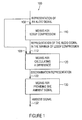
- Fig. 1 shows a block diagram of an apparatus for generating an ambient signal from an audio signal.
- the apparatus according to Fig. 1 is in its entirety designated with 100.
- the apparatus 100 is configured to receive an audio signal in a representation that can basically be arbitrarily selected. In other words, the apparatus 100 receives a representation of an audio signal.
- the apparatus 100 comprises means 110 for lossy compression of the audio signal or the representation of the audio signal.
- the means 110 is configured to receive the representation 108 of the audio signal.
- the means 110 generates from the (original) representation 108 of the audio signal a representation in a manner of lossy compression 112 of the audio signal.
- the apparatus 100 further comprises means 120 for calculating a difference between the representation 112 of the audio signal in the manner of lossy compression of the audio signal and the (original) representation 108.
- the means 120 is therefore configured to receive the representation in the manner of lossy compression 112 of the audio signal as well as, in addition, the (original) representation 108 of the audio signal. Based on the (original) representation 108 of the audio signal and the representation in the manner of lossy compression 112 of the audio signal, the means 120 calculates a discrimination representation 122 describing a difference between the (original) representation 108 of the audio signal and the representation in the manner of lossy compression 112 of the audio signal.
- the apparatus 100 further comprises means 130 for providing the ambient signal 132 using and/or based on and/or as a function of the discrimination representation 122.
- the apparatus 100 receives a representation 108 of an audio signal.
- the means 110 generates a representation in the manner of lossy compression 112 of the audio signal.
- the means 120 calculates a discrimination representation 122 describing a difference between the representation 108 of the audio signal and the representation in the manner of lossy compression 112 of the audio signal and/or being a function of the difference mentioned.
- the discrimination representation 122 describes those signal portions of the (original) audio signal described by the representation 108, which are removed and/or not played back in the representation in the manner of lossy compression 112 of the audio signal by means 110 for lossy compression.
- the discrimination representation 122 describes exactly those signal portions having an irregular curve or an irregular energy distribution, i.e., for example, noise-like signal portions.
- the direct portions and/or "localizable signal portions" which are of particular importance to the listener, are to be played back by the front loudspeakers (and not by the "back" loudspeakers), the discrimination representation 122 is, concerning this matter, adapted to the requirements of the audio playback.
- the direct portions and/or localizable portions of the original audio signal are contained in the representation in the manner of lossy compression 112 of the audio signal in a manner substantially uncorrupted, and are therefore substantially suppressed in the discrimination representation 122 as is desired.
- the information portions having irregularly distributed energy and/or little localizability are reduced.
- the discrimination representation 112 will still comprise a comparably large portion of the low-energy signal portions and/or signal portions having irregularly distributed energy. Exactly these signal portions not very rich in energy and/or signal portions with irregularly distributed energy, as they are described by the discrimination representation 122, represent information resulting in a particularly good and pleasant auditory impression in playback (by means of the back loudspeakers).
- the discrimination representation 122 signal portions having regularly distributed energy (i.e., for example, localizable signals) are suppressed or attenuated. In contrast to that, in the discrimination representation 122, signal portions having irregularly distributed energy (such as non-localizable signals) are not suppressed and not attenuated. Therefore, in the discrimination representation, signal portions having irregularly distributed energy are emphasized or accentuated as compared to signal portions having regularly distributed energy. Therefore, the discrimination representation is particularly suitable as the ambient signal.
- Regular energy distribution here is meant to be, for example, energy distribution yielding a recurring pattern in a time-frequency representation or yielding a local concentration of energy in the time-frequency representation.
- Irregular energy distribution is, for example, energy distribution not yielding any recurring pattern nor a local concentration of energy in a time-frequency representation.
- the ambient signal substantially comprises signal portions having an unstructured energy distribution (for example unstructured in the time-frequency distribution)
- the representation in the manner of lossy compression of the audio signal substantially comprises signal portions having structured energy distribution (for example structured in the time-frequency representation as described above).
- the means 130 for providing the ambient signal on the basis of the discrimination representation 122 provides an ambient signal that is particularly well adapted to the expectations of a human listener.
- the means 110 for lossy compression may, for example, also be an MP3 audio compressor, an MP4 audio compressor, an ELP audio compressor or an SPR audio compressor.
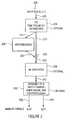
- Fig. 2 shows a block diagram of an apparatus for generating an ambient signal from an audio signal.
- Fig. 3 shows a detailed block diagram of an apparatus for generating an ambient signal from an audio signal.
- the apparatus according to Fig. 2 is designated with 200, and, in its entirety, the apparatus according to Fig. 3 is designated with 300.
- the apparatus 200 is configured to receive an input signal 208 present, for example, in the form of a time representation x[n].
- the input signal 208 typically describes an audio signal.
- the means 200 comprises a time-frequency-distribution provider 210.
- the time-frequency-distribution provider 210 is configured to generate a time-frequency distribution (TFD) from the input signal 208 present in a time representation x[n].
- TFD time-frequency distribution
- the time-frequency-distribution provider 210 is optional. That is, a representation 212 of a time-frequency representation may also serve as the input signal of the apparatus 200 so that in this case the conversion of the input signal 208 (x[n]), which is present as a time signal, to the representation 212 of the time-frequency distribution may be omitted.
- the representation 212 of the time-frequency distribution may, for example, be present in the form of a time-frequency distribution matrix. It is further to be noted that, for example, the matrix X ( ⁇ ,k), which will be explained in greater detail in the following, or else the matrix
- the means 200 further comprises approximation means 220, configured to receive the representation 212 of the time-frequency distribution and to generate an approximated representation 222 of the time-frequency representation 212 that is typically lossily compressed compared to the representation 212.
- approximation or approximated representation 222 of the time-frequency distribution 212 is formed by the means for approximation 220, for example using a numerical optimization method as will be described in further detail in the following. It is assumed, however, that the approximation causes a deviation between the (original) representation 212 of the time-frequency distribution (being an original representation of the audio signal) and the approximated representation 222 of the time-frequency distribution.
- the difference between the original representation 212 and the approximated representation 222 of the time-frequency distribution is based on the fact that the means 220 for approximation is configured to perform a lossy approximation, in which signal portions exhibiting regular distribution of energy and/or carrying a large signal energy are preferred to be carried over to the approximated representation, whereas signal portions exhibiting comparably irregularly distributed energy and/or comparably less signal energy are attenuated or dampened in the approximated representation 222 as compared to the signal portions having regularly distributed energy and/or a large signal energy.
- the apparatus 200 further comprises a difference determinator 230 configured to receive the original representation 212 of the time-frequency distribution as well as the approximated representation 222 of the time-frequency representation so as to generate, based on a difference between the original representation 212 and the approximated representation 222, a discrimination representation 232 essentially describing the difference between the original representation 212 and the approximated representation 222 and/or being a function of the difference between the original representation 212 and the approximated representation 222. Details regarding the calculation of the discrimination representation 232 will be explained in the following.
- the apparatus 200 further comprises re-synthesis means 240.
- the re-synthesis means 240 is configured to receive the discrimination representation 232 so as to generate a re-synthesized signal 242 based thereon.
- the re-synthesis means 240 may for example be configured to convert the discrimination representation 232, which is present in the form of a time-frequency distribution, to a time signal 242.
- the re-synthesis means 240 is optional and may be omitted if direct reprocessing of the discrimination representation 232, which may, for example, be present in the form of a time-frequency distribution, if desired.
- the means 200 further comprises optional means 250 for assembling a multi-channel audio signal and/or for postprocessing.
- the means 250 is, for example, configured to receive the re-synthesized signal 242 from the means 240 for re-synthesis and to generate a plurality of ambient signals 252, 254 (also denoted with a 1 [n], ..., a k [n]) from the re-synthesized signal 242.
- FIG. 2 The block diagram of Fig. 2 has served to provide a brief overview of the concept which the present invention is based on. This concept may be summarized in short as follows:
- a time-frequency distribution 212 (TFD) of the input signal 208 (x[n]) is (optionally) computed in (optional) means 210 for determining the time-frequency distribution.
- the computation will be explained in greater detail in the following.
- An approximation 220 of the time-frequency distribution 212 (TFD) of the input signal 208 (x[n]) is, for example, computed using a method for numerical approximation that will be described in greater detail in the following. This computation may, for example, be performed in the means 220 for approximation.
- an estimation 232 of a time-frequency distribution (TFD) of the ambient signal is obtained.
- a re-synthesis of a time signal 242 of the ambient signal is performed (for example in the optional re-synthesis means 240). The re-synthesis will be explained in greater detail in the following.
- postprocessing realized for example in the optional means 250 for assembling a multi-channel audio signal and/or for postprocessing
- the optional postprocessing will also be explained in greater detail in the following.
- FIG. 3 shows a more detailed block diagram of an apparatus for generating an ambient signal from an audio signal.
- the apparatus 300 is configured to receive an input signal 308 present, for example, in the form of a time-continuous input signal x(t) or in the form of a time-discrete input signal x[n]. Otherwise, the input signal 308 corresponds to the input signal 208 of the apparatus 200.
- the apparatus 300 further comprises a time-signal-to-time-frequency-distribution converter 310.
- the time-signal-to-time-frequency-distribution converter 310 is configured to receive the input signal 308 and to provide a representation of a time-frequency distribution (TFD) 312.
- TFD time-frequency distribution
- the representation 312 of the time-frequency distribution otherwise substantially corresponds to the representation 212 of the time-frequency distribution in the apparatus 200. It is to be further noted that in the following, the time-frequency distribution is also denoted with X ( ⁇ ,k).
- the time-frequency distribution X ( ⁇ ,k) may also be the input signal of the apparatus 300, i.e., that the apparatus 310 may be omitted.
- the apparatus 300 further (optionally) comprises a magnitude-phase splitter 314.
- the magnitude-phase splitter 314 is preferably used when the time-frequency distribution 312 may adopt complex (not purely real) values.
- the magnitude-phase splitter 314 is preferably configured to provide a magnitude representation 316 of the time-frequency distribution 312 as well as a phase representation 318 of the time-frequency distribution 312, based on the time-frequency distribution 312.
- the magnitude representation of the time-frequency distribution 312 is otherwise also designated with
- phase representation 318 of the time-frequency distribution 312 is optional. It is also to be noted that the phase representation 318 of the time-frequency distribution 312 is in some cases also designated with ⁇ ( ⁇ ,k).
- the magnitude representation 316 of the time-frequency distribution 312 is present in the form of a matrix.
- the apparatus 300 further comprises a matrix approximator 320 configured to approximate the magnitude representation 316 of the time-frequency distribution 312 by a product of two matrices W , H , as it will be described in the following.
- the matrix approximator 320 substantially corresponds to the means 220 for approximation as it is used in the apparatus 200.
- the matrix approximator 320 therefore receives the magnitude representation 316 of the time-frequency distribution 312 and provides an approximation 322 of the magnitude representation 316.
- the approximation 322 is in come cases also designated with X ⁇ ( ⁇ ,k). Otherwise, the approximation 322 corresponds to the approximated representation 222 in Fig. 2 .
- the apparatus 300 further comprises a difference former 330 that receives both the magnitude representation 316 and the approximation 322. Furthermore, the difference former 330 provides a discrimination representation 332 that substantially corresponds to the representation
- the apparatus 300 further comprises a phase adder 334.
- the phase adder 334 receives the discrimination representation 332 as well as the phase representation 318 and therefore adds a phase to the elements of the discrimination representation 332 as described by the phase representation 318. Therefore, the phase adder 334 provides a discrimination representation 336 provided with a phase, which is also designated with A ( ⁇ ,k).
- the phase adder 334 may be regarded as optional, so that, if the phase adder 334 is omitted, the discrimination representation 332 may, for example, be substituted for the discrimination representation 336 provided with a phase.
- both the discrimination representation 332 and the discrimination representation 336 provided with a phase may correspond to the discrimination representation 232.
- the apparatus 300 further comprises an (optional) time-frequency-distribution-to-time-signal converter 340.
- the (optional) time-frequency-distribution-to-time-signal converter 340 is configured to receive the discrimination representation 336 provided with a phase (alternatively: the discrimination representation 332) and provide a time signal 342 (also designated with a(t) or a[n]) forming a time-domain representation (or time-signal representation) of the ambient signal.
- time-frequency-distribution-to-time-signal converter 340 substantially corresponds to the re-synthesis means 240 according to Fig. 2 .
- signal 342 provided by the time-frequency-distribution-to-time-signal converter 340 substantially corresponds to the signal 242, as it is shown in the apparatus 200.
- Time-frequency distributions are representations and/or illustrations of a time signal (i.e., for example, of the input signal 208 or the input signal 308) both versus time and also versus frequency.
- a time-frequency distribution e.g. using a filter bank or a discrete cosine transform (DCT)
- DCT discrete cosine transform
- STFT short-time Fourier transform
- w[n] denotes the window function.
- the relation of the index m to the frame index (or time index) k is a function of the window length and the quantity of an overlap of adjacent windows.
- the further computation may be effected using absolute values of the coefficients of the time-frequency distribution (TFD).
- the absolute values and/or magnitudes of the coefficients of the time-frequency distribution (TFD) are also designated with
- a phase information ⁇ ( ⁇ ,k) ⁇ X ( ⁇ ,k) is stored in the re-synthesis stage for later use.
- is designated with 316.
- the phase information ⁇ ( ⁇ ,k) is designated with 318.
- X( ⁇ ,k) denotes individual Fourier coefficients (generally: individual coefficients of a time-frequency distribution) as they may be obtained, for example, by the STFT.
- X ( ⁇ ,k) denotes a matrix containing a plurality of coefficients ( ⁇ ,k).
- n is a first dimension of the matrix X (m,k 1 ), for example a number of rows
- m is a second dimension of the matrix X ( ⁇ ,k 1 ).
- the matrix X ( ⁇ ,k) comprises a plurality of time-frequency-distribution values X( ⁇ ,k).
- An approximation of the time-frequency distribution of the input signal is computed using a numerical optimization method.
- the approximation of the time-frequency distribution as well as the numerical optimization method are described in the following.
- minimization means a minimization with a relative error of not more than 50%, preferably not more than 20%. Otherwise, a minimization may be a determination of an absolute or local minimum.
- the approximation error is measured with the help of a distance function or a divergence function.
- the divergence may be unsymmetrical.
- the approximation of the time-frequency distribution or the time-frequency-distribution matrix X ( ⁇ ,k) described in the following may, for example, be effected by means of the approximation means 220 or the matrix approximator 320.
- NMF non-negative matrix factorization
- NMF Non-negative matrix factorization
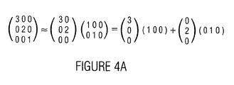
- a non-negative matrix factorization is an approximation of a matrix V ⁇ R nxm with non-negative elements, as a product of two matrices W ⁇ R nxr and H ⁇ R rxm .
- W i,k of the matrix W and H i,k of the matrix H the following is true: W i , k ⁇ 0 ; and H i , k ⁇ 0.
- the matrices W and H are determined such that the following is true: V ⁇ WH
- Equation (2) the matrix V ⁇ R nxm is approximated as the sum of r external products of a column vector w i and a row vector h i , wherein the following is true: i ⁇ [1, r], w i ⁇ R nx1 and h i ⁇ R 1xm .
- the subject-matter described is represented by a simple example in Fig. 4a .
- NMF non-negative matrix factorization
- the cost function c measures the error of the approximation, i.e. the distance (and/or the divergence) between the matrices V and WH .
- GKLD generalized Kullback-Leibler divergence
- Equation 4 The generalized Kullback-Leibler divergence (GKLD) is more related to a Poisson distribution (see [9]) or an exponential distribution and therefore even more suitable for an approximation of quantity or magnitude spectra of musical audio signals.
- a ij and B ij are the entries or matrix elements of the matrices A and B , respectively.
- the additive update rule or iteration rule is given by the following equations: H ik ⁇ H ik + ⁇ ⁇ W T ⁇ V ik - W T ⁇ WH ik W ik ⁇ W ik + ⁇ ⁇ VH T ik - WHH T ik
- V X ⁇ ⁇ k .
- V X ⁇ ⁇ k .
- the speed and robustness of the gradient-descent method strongly depends on the correct choice of the step size or step width ⁇ .
- One principal advantage of the multiplicative update rule over the gradient-descent method is the independence of the choice of the step size or the step width.
- the procedure and method is easy to implement, computationally efficient and guarantees finding a local minimum of the cost function.
- NMF Non-negative matrix factorization
- a non-negative matrix factorization is used to compute an approximation of the quantity or magnitude spectrogram
- is derived from the matrix X ( ⁇ ,k) by performing an element-wise magnitude formation.
- designated with
- X( ⁇ ,k) ij here designates an element of the matrix X ( ⁇ ,k) with the indices i and j.
- NMF non-negative matrix factorization
- of the ambient signal is basically derived by computing the difference between the quantity or magnitude representation
- of the time-frequency distribution X and its approximation WH , as is represented in equation (10): A X - WH
- equation 10 is preferably not considered directly as will be explained in the following. That is, for approximations minimizing the cost functions described above, the application of the equation (10) results in a quantity or magnitude spectrogram
- ik is a matrix element of the quantity or magnitude spectrogram
- the optimization method for determining the entries of the matrices W and H is adapted such that the difference mentioned preferably comprises positive values and/or comparably less negative values (or vice versa).
- ⁇ is a constant determining the influence of the boundary constraint or boundary condition on the total cost (or on the total value of the cost function c).
- the update rule and/or iteration rule for the gradient descent is derived by inserting the derivation operator ⁇ c/ ⁇ H (according to equation 14) and the derivation operator ⁇ c/ ⁇ W into equation (5).
- described above may be executed, for example by the difference determination means 230 or the difference former 330.
- X of the input signal 308 (also designated with x(t), x[n]) is calculated according to equation (16):
- a ⁇ ⁇ k A ⁇ ⁇ k ⁇ cos ⁇ ⁇ ⁇ k + j ⁇ sin ⁇ ⁇ ⁇ k
- ⁇ is, for example, a matrix of angle values.
- the phase information or angle information of the time-frequency distribution (TFD) X is added element-wisely to the quantity or magnitude representation
- the phase information of an entry or matrix element X i,j with a row index i and a column index j is added, for example by multiplication with a respective complex number of the magnitude 1.
- the overall result is a representation A ( ⁇ ,k) of the ambient signal provided with a phase information (designated with 336).
- the ambient signal a[n] (or a time-discrete representation of the ambient signal or else a time-continuous representation of the ambient signal) is then (optionally) derived from the representation A ( ⁇ ,k) provided with a phase information, by subjecting A ( ⁇ ,k) to an inverse process of computing the time-frequency distribution (TFD). That is, a representation A ( ⁇ ,k) provided with a phase information is, for example, processed by an inverse short-time Fourier transform with an overlap-and-add scheme resulting in the time signal x[n] when applied to X ( ⁇ ,k).
- the procedure described is otherwise applied to overlapping segments of a few seconds length each.
- the segments are windowed using a Hann window to ensure smooth transition between adjacent segments.
- the procedures for deriving the time representation a[n] of the ambient signal described last may, for example, be effected in the means 240 for re-synthesis or in the time-frequency-distribution-to-time-signal converter 340.
- a 5.0 signal or a 5.0 audio signal (i.e., for example, an audio signal comprising a rear left channel, a front center channel, as well as a front right channel, a rear left channel and a rear right channel) is obtained by feeding the rear channels (i.e., for example, at least the rear left channel or the rear right channel, or both the rear left channel and the rear right channel) with the ambient signal.
- the front channels i.e., for example, the front left channel, the center channel and/or the front right channel
- gain parameters and/or loudness parameters ensure that a total energy is obtained (or remains substantially unchanged) when the additional center channel is used.
- the described concept for generating an ambient signal may be employed in any multi-channel system and multi-channel audio playback systems, for example, in a 7.0 system (for example in a system having three front loudspeakers, two side loudspeakers and two back loudspeakers).
- the ambient signal may, for example, be supplied to one or both side loudspeakers and/or one or both back loudspeakers.
- additional processing may optionally be carried out in order to obtain a multi-channel audio signal of high perceptual quality.
- a multi-channel audio signal from one single channel, it is desired that the front image is preserved while the impression of spaciousness is added. This is, for example, achieved by introducing or adding delay of a few milliseconds to the ambient signal and/or by suppressing transient portions in the ambient signal.
- decorrelation of the signals feeding the rear loudspeakers or back loudspeakers among one another and/or in relation to the signals feeding the front loudspeakers is advantageous.
- Algorithms for the detection of transients (and/or peaks or settling operations) and for manipulating transients are used in various audio signal processing applications, such as for digital audio effects (see [11, 12]) and for upmixing (see [13]).
- the suppression of transients in the context of upmixing aims to maintain the front image.
- sources generating these transients are not localized in the front. This is an undesired effect: the "direct sound source” either appears wider (or more extended) than in the original or, even worse, is perceived as an independent "direct sound source” in the back of the listener.
- the term “decorrelation” describes a process that manipulates an input signal such that (2 or more) output signals exhibit different waveforms but sound the same as the input signal (see [14]). If, for example, two similar, coherent wide-band noise signals are simultaneously played back or presented by a pair of loudspeakers, a compact auditory event will be perceived (see [15]). Decreasing the correlation of the two channel signals increases the perceived width or extension of the sound source or noise source up until two separate sources are perceived.
- 2 ⁇ ⁇ k - l l y k 2
- y* (k) denotes the number conjugated complex to y(k).
- ⁇ the inter-channel correlation or inter-channel coherence ⁇
- decorrelating processes are natural reverberation and several signal processors (flanger, chorus, phaser, synthetic reverberation).
- a pair of output signals with a given or specified correlation measure are generated by convoluting the input signal with a pair of pulse responses that are correlated to each other according to the given value (see [14]).
- a dynamic (i.e. time-variable) decorrelation is obtained by using time-variable allpass filters, i.e., allpass filters in which new random phase responses are calculated for adjacent timeframes (see [18], [11]).
- a decorrelation is applied to the ambient signal.
- a 5.1 setup i.e. in a setup with, for example, six loudspeakers
- the ambient signals that are finally fed to the two rear or back channels are decorrelated relative to each other at least to a certain extent.
- the desired properties of the present method are sound-field diffusion (or noise-field diffusion or sound-field broadening or noise-field broadening) and envelopment.
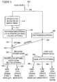
- the apparatus for deriving the multi-channel audio signal according to Fig. 5 is in its entirety designated with 500.
- the apparatus 500 receives the audio signal 508 or a representation 508 of the audio signal.
- Apparatus 500 comprises an apparatus 510 for generating an ambient signal, wherein the apparatus 510 receives the audio signal 508 or the representation 508 of the audio signal.
- the apparatus 510 provides an ambient signal 512. It is to be noted that, preferably, the apparatus 510 is the apparatus 100 according to Fig. 1 , the apparatus 200 according to Fig. 2 or the apparatus 300 according to Fig. 3 .
- the ambient signal 512 which may be present in the form of a time-domain representation (or time-signal representation) and/or in a time-frequency representation is further fed to postprocessing means 520.
- the postprocessing means 520 is optional and may, for example, comprise a pulse reducer configured to reduce or remove transients present in the ambient signal 512.
- the transients are high-energy signal portions that may exhibit an edge steepness greater than a given maximum permissible edge steepness.
- transient events may otherwise also be signal peaks in the ambient signal 512, the amplitudes of which exceed a certain given maximum amplitude.
- the postprocessing means 520 may (optionally) comprise a delayer or delaying means delaying the ambient signal 512.
- the postprocessing means 520 therefore provides a postprocessed ambient signal 522 in which, for example, transients are reduced or removed compared to the (original) ambient signal 512 and/or which is for example delayed compared to the (original) ambient signal 512.
- the signal 522 may be identical to the signal 512.
- the apparatus 500 further (optionally) comprises a combiner 530. If the combiner is included, the combiner 520 for example provides a back-loudspeaker signal 532, which is formed by a combination of the postprocessed ambient signal 522 and an (optionally postprocessed) version of the original audio signal 508.
- the apparatus 500 further (optionally) comprises a decorrelator 540, which receives the back-loudspeaker signal 532 and based thereon supplies at least two decorrelated back-loudspeaker signals 542, 544.
- the first back-loudspeaker signal 542 may, for example, represent a back-loudspeaker signal for a rear left back loudspeaker.
- the second back-loudspeaker signal 544 may, for example, represent a back-loudspeaker signal for a rear right back loudspeaker.
- the ambient signal 512 generated by the apparatus 510 is used as the first back-loudspeaker signal 542 and/or as the second back-loudspeaker signal 544.
- the ambient signal 512 generated by the apparatus 510 is considered for generating the first back-loudspeaker signal 542 and/or for generating the second back-loudspeaker signal 544.
- the present invention therefore explicitly comprises using the ambient signal 512 generated by the apparatus 510 as a first back-loudspeaker signal 542 and/or as a second back-loudspeaker signal 544.
- the present invention explicitly also comprises generating the first back-loudspeaker signal 542 and/or the second back-loudspeaker signal 544 using the ambient signal 512 generated by the apparatus 510.
- the apparatus may further, optionally, additionally be configured to generate a first front-loudspeaker signal, a second front-loudspeaker signal and/or a third front-loudspeaker signal.
- the (original) audio signal 508 is fed to postprocessing means 550.
- the postprocessing means 550 is configured to receive and process the audio signal 508 and generate a postprocessed audio signal 552, which is, for example, (optionally) fed to the combiner 530. If the postprocessing means is omitted, the signal 542 may be identical to the signal 508.
- the signal 552 otherwise forms a front-loudspeaker signal.
- the apparatus 500 comprises a signal splitter 560 configured to receive the front-loudspeaker signal 552 and generate, based thereon, a first front-loudspeaker signal 562, a second front-loudspeaker signal 564 and/or a third front-loudspeaker signal 566.
- the first front-loudspeaker signal 562 may, for example, be a loudspeaker signal for a loudspeaker located front left.
- the second front-loudspeaker signal 564 may, for example, be a loudspeaker signal for a loudspeaker located front right.
- the third front-loudspeaker signal 566 may, for example, be a loudspeaker signal for a loudspeaker located front center.
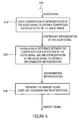
- Fig. 6 otherwise shows a flowchart of a method for creating an ambient signal from an audio signal.
- the method according to Fig. 6 is in its entirety designated with 600.
- the method 600 comprises a first step 610.
- the first step 610 comprises lossy compression of the audio signal (or of a representation of the audio signal) so as to obtain a representation of the audio signal in the manner of lossy compression.
- a second step 620 of the method 600 comprises calculating a difference between the compressed representation of the audio signal and the representation of the audio signal so as to obtain a discrimination representation.
- a third step 630 comprises providing an ambient signal using the discrimination representation. Therefore, as a whole, the method 600 enables the generation of an ambient signal from an audio signal.
- the method 600 according to Fig. 6 may be supplemented by those steps that are executed by the above apparatuses.
- the method may, for example, be modified and/or supplemented so as to fulfill the function of the apparatus 100 according to Fig. 2 , the function of the apparatus 200 according to Fig. 2 , the function of the apparatus 300 according to Fig. 3 and/or the function of the apparatus 500 according to Fig. 5 .
- the apparatus and the method may be implemented in hardware or in software.
- the implementation may be effected on a digital storage medium such as a floppy disc, a CD, a DVD or a FLASH memory with electronically readable control signals cooperating such with a programmable computer system that the respective method is executed.
- a computer program as set forth in independent claim 5.
- an ambient signal is generated from the input signal and fed to the rear channels.
- a concept may be used as it is described under the caption "Direct/Ambient Concept”.
- the quintessence of the invention relates to the calculation of the ambient signal, wherein Fig. 2 shows a block diagram of a processing as it may be used for obtaining the ambient signal.
- a time-frequency distribution (TFD) of the input signal is calculated as discussed under the caption "Time-frequency distribution of the input signal”.
- An approximation of the time-frequency distribution (TFD) of the input signal is calculated using the method of numerical optimization as described in the section “Approximation of the time-frequency distribution”.
- an estimate of the time-frequency distribution (TFD) of the ambient signal is obtained.
- the estimate is also designated with
- a re-synthesis of the time signal of the ambient signal is otherwise explained in the section under the caption "Reconstruction of the time signal”.
- postprocessing may (optionally) be used for enhancing the auditory impression of the derived multi-channel signal, as it is described under the caption "Assembly of a multi-channel audio signal”.
- the above describes a method and concept for separating an ambient signal from one-channel audio signals (or from one one-channel audio signal).
- the derived ambient signal exhibits high audio quality. It comprises sound elements or noise elements originating from ambience, i.e. reverberance, audience noise as well as ambience noise or environmental noise.
- the amount or volume of direct sound or direct noise in the ambient signal is very low or even evanescent.
- the time-frequency distributions (TFD) of direct sound or direct noise are generally sparser or less dense than the time-frequency distributions (TFD) of ambient noise or ambient sound. That is, the energy of direct noise or direct sound is more concentrated in less bins or matrix entries than the energy of ambient noise or ambient sound. Therefore, the approximation detects direct noise or direct sound, but not (or only to a very little extent) ambient noise or ambient sound. Alternatively, it can be said that the approximation detects direct noise or direct sound to a greater extent than ambient noise or ambient sound.
- the distinction or difference between the time-frequency distribution (TFD) of the input signal and its approximation is therefore a good representation of the time-frequency distribution (TFD) of all ambient noise and/or ambient sound present in the input signal.
- the above comprises a method of calculating multi-channel signals (or one multi-channel signal) from a one-channel signal or a two-channel signal (or from one-channel signals or two-channel signals).
- the use of the described method and concept therefore enables the rendition of conventional recordings on a multi-channel system (or multi-channel systems) in a manner in which the advantages of the multi-signal rendering are maintained.
- the described method and concept overcome substantial drawbacks of known methods or concepts.
- the signaladaptive methods described in the introduction calculate the back-channel signal (i.e., the signal for the rear loudspeakers) by calculating inter-channel differences of the two-channel input signal. These methods are therefore not capable of generating a multi-channel signal from an input signal according to option 3 when both channels of the input signal are identical (i.e., when the input signal is a dual-mono signal) or when the signals of the two channels are almost identical.
- the method and concept described herein are capable of generating an ambient signal from a one-channel signal without any previous information on the signal. Furthermore, no synthetic audio objects or audio effects (such as reverberance) are used.
- the parameter FFT size (nfft) describes how many frequency bands are processed.
- the parameter FFT size indicates, how many discriminable frequencies ⁇ 1 to ⁇ n exist. Therefore, the parameter FFT size is also a measure of how large a first dimension (for example a number of matrix rows) of the matrix X ( ⁇ ,k) is.
- the parameter FFT size preferably describes the number of rows (or columns) of the matrix X ( ⁇ ,k). Therefore, the parameter FFT size for example corresponds to the value n.
- the value FFT size also describes how many samples are used for the calculation of one single entry X i,j of the matrix X .
- nfft samples of a time representation of the input signal are used in order to calculate based thereon nfft spectral coefficients for nfft different frequencies ⁇ 1 to ⁇ nfft . Therefore, based on nfft samples, a column of the matrix X ( ⁇ ,k) is calculated.
- the window defining the contemplated samples of the input signal is then shifted by a number of samples defined by the parameter hop.
- the nfft samples of the input signal defined by the shifted window are then mapped to nfft spectral coefficients by a Fourier transform, the spectral coefficient defining a next column of the matrix X .
- the first column of the matrix X may be formed by a Fourier transform of the samples of the input signal with the indices 1 to nfft.
- the second column of the matrix X may be formed by a Fourier transform of samples of the input signal with the indices 1 + hop to nfft + hop.
- the parameter segment length indicates how long one segment of a signal frame is, the spectrogram of which is factorized.
- the parameter segment length describes how long a time duration of the input audio signal is that is considered for calculating the entries of the matrix X . Therefore, it can be said that the matrix X describes the input time signal over a time period equal to the parameter segment length (segLen).
- the parameter factorization rank describes the factorization rank of the non-negative matrix factorization, i.e., the parameter r.
- the parameter factorization rank indicates how large a dimension of the first approximation matrix W and a dimension of the second approximation matrix H are.
- FFT size Size of a signal frame for FFT Samples 1024 4096 2048 or 4096 Hop size (hop) Hop size for FFT Samples 1 nfft 0.125*nfft or 0.20.25* nfft Segment length (segLen) Size of a signal frame the spectrogram of which is being factorized Seconds 1 Length of the input signal 2-4 Factorization rank Factorization rank of NMF 10 Number of columns of the spectrogram 40...100
- error measure c is used for the calculation of the NMF.
- the use of the Kullback-Leibler divergence is preferred when quantity or magnitude spectrograms are processed.
- Other distance measures may be used when spectrogram values with the logarithm taken (SPL) or energy spectrogram values are processed.
- the FFT size may be in a range from 128 to 65,536.
- the hop size may be between 1/64 of the FFT size and a unity of the FFT size.
- the segment length typically amounts to at least 0.1 seconds,
- the present invention comprises a new concept or method for calculating an ambient signal from an audio signal.
- the derived ambient signal is of particular benefit for upmixing music audio signals for playback on multi-channel systems.
- One advantage of the described inventive concept or method compared to other methods, is its ability to process one-channel signals without using synthetic audio effects.
- the present invention may also be used in a simple system.
- a system may be contemplated, in which only one front loudspeaker and one back loudspeaker are present and/or active.
- the original audio signal may be played back on the front loudspeaker.
- the ambient signal derived from the original audio signal may be played back on the back loudspeaker.
- the original mono audio signal may be played back as a mono signal over one front loudspeaker only, whereas the ambient signal derived from the original audio signal is played back as one single back channel.
- a first channel of the original audio signal is considered for generating a first ambient signal
- a second channel of the original audio signal is used for generating a second ambient signal.
- the first channel of the original audio signal is then played back, for example, on a first front loudspeaker (e.g. front left)
- the second channel of the original audio signal is, for example, played back on a second front loudspeaker (e.g. front right).
- the first ambient signal is played back on a first back loudspeaker (e.g. rear left)
- the second ambient signal is, for example, played back on a second back loudspeaker (e.g. rear right).
- the original audio signal comprises three channels, for example a front left channel, a front center channel and a front right channel. Therefore, a first ambient signal is obtained from the first channel (e.g. front left channel) of the original audio signal. From the second channel (e.g. front center channel) of the original audio signal, a second ambient signal is obtained. From the third channel (e.g. front right channel) of the original audio signal, a third ambient signal is (optionally) obtained.
- Two of the ambient signals are then combined (e.g. mixed or combined by weighted or unweighted summation) so as to obtain a first ambience loudspeaker signal, which is fed to a first ambience loudspeaker (e.g. a rear left loudspeaker).
- a first ambience loudspeaker e.g. a rear left loudspeaker
- two further ambient signals are combined to obtain a second ambience-loudspeaker signal fed to a second ambience loudspeaker (e.g. a rear right loudspeaker).
- a second ambience loudspeaker e.g. a rear right loudspeaker
- a first ambience-loudspeaker signal is formed by a first combination of ambient signals, each formed from a channel of the original multi-channel audio signal, whereas a second ambience-loudspeaker signal is formed by a second combination of the ambient signals.
- the first combination preferably comprises at least two ambient signals
- the second combination preferably comprises at least two ambient signals.
- the first combination be different from the second combination, wherein, however, it is preferred that the first combination and the second combination use a common ambient signal.
- an ambient signal generated in the inventive manner may, for example, also be fed to a side loudspeaker if, for example, a loudspeaker arrangement is used that comprises side loudspeakers. Therefore, an ambient signal may be fed to a left side loudspeaker in a use of a 7.1 loudspeaker arrangement. Furthermore, an ambient signal may also be fed to the right side loudspeaker, wherein the ambient signal fed to the left side loudspeaker preferably differs from the ambient signal fed to the right side loudspeaker.
- the present invention brings about particularly good extraction of an ambient signal from a one-channel signal.
Landscapes
- Engineering & Computer Science (AREA)
- Physics & Mathematics (AREA)
- Signal Processing (AREA)
- Acoustics & Sound (AREA)
- Audiology, Speech & Language Pathology (AREA)
- Health & Medical Sciences (AREA)
- Computational Linguistics (AREA)
- Human Computer Interaction (AREA)
- Multimedia (AREA)
- Mathematical Physics (AREA)
- Spectroscopy & Molecular Physics (AREA)
- Theoretical Computer Science (AREA)
- Stereophonic System (AREA)
Claims (5)
- Vorrichtung (500) zum Ableiten eines Mehrkanal-Audiosignals, das ein Front-Lautsprecher-Signal (562, 564, 566) und ein Rücken-Lautsprecher-Signal (542, 544) umfasst, aus einem Audiosignal (108; 208; 308; 508), mit folgenden Merkmalen:einer Vorrichtung (100; 200; 300; 510) zum Erzeugen eines Umgebungssignals (132; 232, 242, 252, 254; 332, 336, 342; 512) aus dem Audiosignal (108; 208; 308; 508),wobei die Vorrichtung (100; 200; 300; 510) zum Erzeugen des Umgebungssignals (132; 232, 242, 252, 254; 332, 336, 342; 512) aus dem Audiosignal (108; 208; 308; 508) folgende Merkmale aufweist:eine Einrichtung (110; 220; 320) zum verlustbehafteten Komprimieren einer ersten Darstellung (108; 212; 316; X(ω,k)) des Audiosignals, um eine komprimierte Darstellung (112; 222; 322; X̂ (ω,k)) des Audiosignals zu erhalten; undeine Einrichtung (120; 230; 330) zum Berechnen eines Unterschieds zwischen der komprimierten Darstellung (112; 222; 322; X̂ (ω,k)) des Audiosignals und der ersten Darstellung (108; 212; 316; X(ω,k)) des Audiosignals, um eine Unterscheidungsdarstellung (122; 232; 332, 336; |A(ω, k)|) zu erhalten,wobei die Unterscheidungsdarstellung den Unterschied zwischen der ersten Darstellung des Audiosignals und der komprimierten Darstellung des Audiosignals beschreibt, unddie Unterscheidungsdarstellung diejenigen Anteile des Audiosignals beschreibt, die nicht in die verlustbehaftet komprimierte Darstellung integriert sind oder in der verlustbehaftet komprimierten Darstellung beseitigt sind, undwobei die Einrichtung zum verlustbehafteten Komprimieren so ausgelegt ist, dass Signalanteile, die eine regelmäßige Verteilung der Energie aufweisen oder eine große Signalenergie tragen, bevorzugt in die komprimierte Darstellung aufgenommen werden, während Signalanteile, die eine unregelmäßig verteilte Energie oder eine geringere Energie aufweisen, in abgeschwächter Form oder lediglich in einem geringen Umfang in die komprimierte Darstellung übernommen werden;wobei die Unterscheidungsdarstellung das Umgebungssignal bildet;einer Vorrichtung (550, 560) zum Bereitstellen des Audiosignals (108; 208; 308; 508) oder eines davon abgeleiteten Signals als das Front-Lautsprecher-Signal (562, 564, 566); undeiner Rücken-Lautsprecher-Signal-Bereitstellungsvorrichtung (520, 530, 540) zum Bereitstellen des durch die Vorrichtung (510) zum Erzeugen des Umgebungssignals (132; 232, 242, 252, 254; 332, 336, 342; 512) bereitgestellten Umgebungssignals (132; 232, 242, 252, 254; 332, 336, 342; 512) oder eines davon abgeleiteten Signals als das Rücken-Lautsprecher-Signal (542, 544).
- Vorrichtung (500) zum Ableiten eines Mehrkanal-Audiosignals, das ein Front-Lautsprecher-Signal (562, 564, 566) und ein Rücken-Lautsprecher-Signal (542, 544) umfasst, aus einem Audiosignal (108; 208; 308; 508), mit folgenden Merkmalen:einer Vorrichtung (100; 200; 300; 510) zum Erzeugen eines Umgebungssignals (132; 232, 242, 252, 254; 332, 336, 342; 512) aus dem Audiosignal (108; 208; 308; 508),wobei die Vorrichtung (100; 200; 300; 510) zum Erzeugen des Umgebungssignals (132; 232, 242, 252, 254; 332, 336, 342; 512) aus dem Audiosignal (108; 208; 308; 508) folgende Merkmale aufweist:eine Einrichtung (110; 220; 320) zum verlustbehafteten Komprimieren einer ersten Darstellung (108; 212; 316; X(ω,k)) des Audiosignals, um eine komprimierte Darstellung (112; 222; 322; X̂ (ω,k)) des Audiosignals zu erhalten, undeine Einrichtung (120; 230; 330) zum Berechnen eines Unterschieds zwischen der komprimierten Darstellung (112; 222; 322; X̂ (ω,k)) des Audiosignals und der ersten Darstellung (108; 212; 316; X(ω,k)) des Audiosignals, um eine Unterscheidungsdarstellung (122; 232; 332, 336; |A(ω, k)|) zu erhalten,wobei die Unterscheidungsdarstellung den Unterschied zwischen der ersten Darstellung des Audiosignals und der komprimierten Darstellung des Audiosignals beschreibt, unddie Unterscheidungsdarstellung diejenigen Anteile des Audiosignals beschreibt, die nicht in die verlustbehaftet komprimierte Darstellung integriert sind oder in der verlustbehaftet komprimierten Darstellung beseitigt sind, undeine Einrichtung (130, 240, 340) zum Bereitstellen des Umgebungssignals (132; 242, 252, 254; 336, 342; a(t), a[n]) unter Verwendung der Unterscheidungsdarstellung,wobei die Einrichtung zum verlustbehafteten Komprimieren so ausgelegt ist, dass Signalanteile, die eine regelmäßige Verteilung der Energie aufweisen oder eine große Signalenergie tragen, bevorzugt in die komprimierte Darstellung aufgenommen werden, während Signalanteile, die eine unregelmäßig verteilte Energie oder eine geringere Energie aufweisen, in abgeschwächter Form oder lediglich in einem geringen Umfang in die komprimierte Darstellung übernommen werden;wobei die Vorrichtung (510) zum Erzeugen des Umgebungssignals (132; 230, 242, 252, 254; 332, 336, 342; 512) dazu konfiguriert ist, das Audiosignal (108; 208; 308; 508) zu empfangen;einer Vorrichtung (550, 560) zum Bereitstellen des Audiosignals (108; 208; 308; 508) oder eines davon abgeleiteten Signals als das Front-Lautsprecher-Signal (562, 564, 566); undeiner Rücken-Lautsprecher-Signal-Bereitstellungsvorrichtung (520, 530, 540) zum Bereitstellen des durch die Vorrichtung (510) zum Erzeugen des Umgebungssignals (132; 230, 242, 252, 254; 332, 336, 342; 512) bereitgestellten Umgebungssignals (132; 230, 242, 252, 254; 332, 336, 342; 512) oder eines davon abgeleiteten Signals als das Rücken-Lautsprecher-Signal (542, 544).
- Verfahren zum Ableiten eines Mehrkanal-Audiosignals, das ein Front-Lautsprecher-Signal und ein Rücken-Lautsprecher-Signal umfasst, aus einem Audiosignal, mit folgenden Schritten:Erzeugen eines Umgebungssignals aus dem Audiosignal, wobei das Erzeugen des Umgebungssignals aus dem Audiosignalein verlustbehaftetes Komprimieren (610) einer ersten Darstellung (108; 212; 316) des Audiosignals, um eine komprimierte Darstellung (112; 222; 322) des Audiosignals zu erhalten; undein Berechnen (620) eines Unterschieds (122; 232; 332, 336) zwischen der komprimierten Darstellung des Audiosignals und der ersten Darstellung des Audiosignals, um eine Unterscheidungsdarstellung (122; 232; 332, 336) zu erhalten, die das Umgebungssignal bildet,umfasst,wobei die Unterscheidungsdarstellung den Unterschied zwischen der ersten Darstellung des Audiosignals und der komprimierten Darstellung des Audiosignals beschreibt, undwobei die Unterscheidungsdarstellung diejenigen Anteile des Audiosignals beschreibt, die nicht in die verlustbehaftet komprimierte Darstellung integriert sind oder in der verlustbehaftet komprimierten Darstellung beseitigt sind, undwobei das verlustbehaftete Komprimieren derart erfolgt, dass Signalanteile, die eine regelmäßige Verteilung der Energie aufweisen oder eine große Signalenergie tragen, bevorzugt in die komprimierte Darstellung aufgenommen werden, während Signalanteile, die eine unregelmäßig verteilte Energie oder eine geringere Energie aufweisen, in abgeschwächter Form oder lediglich in einem geringen Umfang in die komprimierte Darstellung übernommen werden;wobei die Unterscheidungsdarstellung das Umgebungssignal bildet;Bereitstellen des Audiosignals oder eines davon abgeleiteten Signals als das Front-Lautsprecher-Signal; undBereitstellen des Umgebungssignals oder eines davon abgeleiteten Signals als das Rücken-Lautsprecher-Signal.
- Verfahren zum Ableiten eines Mehrkanal-Audiosignals, das ein Front-Lautsprecher-Signal und ein Rücken-Lautsprecher-Signal umfasst, aus einem Audiosignal, mit folgenden Schritten:Erzeugen eines Umgebungssignals aus dem Audiosignal, wobei das Erzeugen des Umgebungssignals aus dem Audiosignalein verlustbehaftetes Komprimieren (610) einer ersten Darstellung (108; 212; 316) des Audiosignals, um eine komprimierte Darstellung (112; 222; 322) des Audiosignals zu erhalten;ein Berechnen (620) eines Unterschieds (122; 232; 332, 336) zwischen der komprimierten Darstellung des Audiosignals und der ersten Darstellung des Audiosignals, um eine Unterscheidungsdarstellung (122; 232; 332, 336) zu erhalten, undein Bereitstellen (630) des Umgebungssignals unter Verwendung der Unterscheidungsdarstellungumfasst,wobei die Unterscheidungsdarstellung den Unterschied zwischen der ersten Darstellung des Audiosignals und der komprimierten Darstellung des Audiosignals beschreibt, undwobei die Unterscheidungsdarstellung diejenigen Anteile des Audiosignals beschreibt, die nicht in die verlustbehaftet komprimierte Darstellung integriert sind oder in der verlustbehaftet komprimierten Darstellung beseitigt sind, undwobei das verlustbehaftete Komprimieren derart erfolgt, dass Signalanteile, die eine regelmäßige Verteilung der Energie aufweisen oder eine große Signalenergie tragen, bevorzugt in die komprimierte Darstellung aufgenommen werden, während Signalanteile, die eine unregelmäßig verteilte Energie oder eine geringere Energie aufweisen, in abgeschwächter Form oder lediglich in einem geringen Umfang in die komprimierte Darstellung übernommen werden; Bereitstellen des Audiosignals oder eines davon abgeleiteten Signals als das Front-Lautsprecher-Signal; undBereitstellen des Umgebungssignals oder eines davon abgeleiteten Signals als das Rücken-Lautsprecher-Signal.
- Computerprogramm zur Durchführung des Verfahrens gemäß Anspruch 3 oder 4, wenn das Computerprogramm auf einem Computer abläuft.
Priority Applications (1)
| Application Number | Priority Date | Filing Date | Title |
|---|---|---|---|
| PL12168768T PL2500900T3 (pl) | 2006-10-24 | 2007-10-23 | Urządzenie, sposób i program komputerowy do uzyskiwania wielokanałowego sygnału audio z sygnału audio |
Applications Claiming Priority (2)
| Application Number | Priority Date | Filing Date | Title |
|---|---|---|---|
| DE102006050068A DE102006050068B4 (de) | 2006-10-24 | 2006-10-24 | Vorrichtung und Verfahren zum Erzeugen eines Umgebungssignals aus einem Audiosignal, Vorrichtung und Verfahren zum Ableiten eines Mehrkanal-Audiosignals aus einem Audiosignal und Computerprogramm |
| EP07819257A EP1997102B1 (de) | 2006-10-24 | 2007-10-23 | Vorrichtung und verfahren zur erzeugung eines umgebungssignals aus einem audiosignal, vorrichtung und verfahren zur ableitung eines mehrkanal-audiosignals aus einem audiosignal und entsprechendes computerprogramm |
Related Parent Applications (1)
| Application Number | Title | Priority Date | Filing Date |
|---|---|---|---|
| EP07819257A Division EP1997102B1 (de) | 2006-10-24 | 2007-10-23 | Vorrichtung und verfahren zur erzeugung eines umgebungssignals aus einem audiosignal, vorrichtung und verfahren zur ableitung eines mehrkanal-audiosignals aus einem audiosignal und entsprechendes computerprogramm |
Publications (2)
| Publication Number | Publication Date |
|---|---|
| EP2500900A1 EP2500900A1 (de) | 2012-09-19 |
| EP2500900B1 true EP2500900B1 (de) | 2014-04-02 |
Family
ID=38988087
Family Applications (2)
| Application Number | Title | Priority Date | Filing Date |
|---|---|---|---|
| EP12168768.5A Active EP2500900B1 (de) | 2006-10-24 | 2007-10-23 | Vorrichtung, Verfahren und Computerprogramm zur Ableitung eines Mehrkanal-Audiosignals aus einem Audiosignal |
| EP07819257A Active EP1997102B1 (de) | 2006-10-24 | 2007-10-23 | Vorrichtung und verfahren zur erzeugung eines umgebungssignals aus einem audiosignal, vorrichtung und verfahren zur ableitung eines mehrkanal-audiosignals aus einem audiosignal und entsprechendes computerprogramm |
Family Applications After (1)
| Application Number | Title | Priority Date | Filing Date |
|---|---|---|---|
| EP07819257A Active EP1997102B1 (de) | 2006-10-24 | 2007-10-23 | Vorrichtung und verfahren zur erzeugung eines umgebungssignals aus einem audiosignal, vorrichtung und verfahren zur ableitung eines mehrkanal-audiosignals aus einem audiosignal und entsprechendes computerprogramm |
Country Status (12)
| Country | Link |
|---|---|
| US (1) | US8346565B2 (de) |
| EP (2) | EP2500900B1 (de) |
| JP (1) | JP5048777B2 (de) |
| KR (1) | KR101090565B1 (de) |
| CN (1) | CN101536085B (de) |
| AU (1) | AU2007308413B2 (de) |
| CA (1) | CA2664163C (de) |
| DE (1) | DE102006050068B4 (de) |
| ES (2) | ES2461191T3 (de) |
| PL (2) | PL1997102T3 (de) |
| TW (1) | TWI352971B (de) |
| WO (1) | WO2008049587A1 (de) |
Families Citing this family (40)
| Publication number | Priority date | Publication date | Assignee | Title |
|---|---|---|---|---|
| EP2595151A3 (de) * | 2006-12-27 | 2013-11-13 | Electronics and Telecommunications Research Institute | Transkodierungsvorrichtung |
| US20080228470A1 (en) * | 2007-02-21 | 2008-09-18 | Atsuo Hiroe | Signal separating device, signal separating method, and computer program |
| RU2483368C2 (ru) * | 2007-11-06 | 2013-05-27 | Нокиа Корпорейшн | Кодер |
| WO2009059631A1 (en) * | 2007-11-06 | 2009-05-14 | Nokia Corporation | Audio coding apparatus and method thereof |
| EP2227682A1 (de) * | 2007-11-06 | 2010-09-15 | Nokia Corporation | Ein kodierer |
| EP2154911A1 (de) * | 2008-08-13 | 2010-02-17 | Fraunhofer-Gesellschaft zur Förderung der angewandten Forschung e.V. | Vorrichtung zur Bestimmung eines räumlichen Mehrkanalausgangsaudiosignals |
| JP5237463B2 (ja) * | 2008-12-11 | 2013-07-17 | フラウンホッファー−ゲゼルシャフト ツァ フェルダールング デァ アンゲヴァンテン フォアシュンク エー.ファオ | マルチチャンネルオーディオ信号を生成するための装置 |
| CN102265643B (zh) * | 2008-12-23 | 2014-11-19 | 皇家飞利浦电子股份有限公司 | 语音再现设备、方法及系统 |
| WO2011044521A1 (en) * | 2009-10-09 | 2011-04-14 | Dts, Inc. | Adaptive dynamic range enhancement of audio recordings |
| EP2502227A1 (de) * | 2009-11-18 | 2012-09-26 | Nokia Corp. | Datenverarbeitung |
| US20120314872A1 (en) * | 2010-01-19 | 2012-12-13 | Ee Leng Tan | System and method for processing an input signal to produce 3d audio effects |
| TWI444989B (zh) * | 2010-01-22 | 2014-07-11 | Dolby Lab Licensing Corp | 針對改良多通道上混使用多通道解相關之技術 |
| WO2011107951A1 (en) * | 2010-03-02 | 2011-09-09 | Nokia Corporation | Method and apparatus for upmixing a two-channel audio signal |
| US9219972B2 (en) * | 2010-11-19 | 2015-12-22 | Nokia Technologies Oy | Efficient audio coding having reduced bit rate for ambient signals and decoding using same |
| CA2779232A1 (en) * | 2011-06-08 | 2012-12-08 | Her Majesty The Queen In Right Of Canada, As Represented By The Minister Of Industry Through The Communications Research Centre Canada | Sparse coding using object extraction |
| EP2544466A1 (de) | 2011-07-05 | 2013-01-09 | Fraunhofer-Gesellschaft zur Förderung der angewandten Forschung e.V. | Verfahren und Vorrichtung zur Zerlegung einer Stereoaufzeichnung mittels Frequenzdomänenverarbeitung unter Verwendung eines spektralen Subtrahieres |
| US9532157B2 (en) | 2011-12-23 | 2016-12-27 | Nokia Technologies Oy | Audio processing for mono signals |
| KR101685408B1 (ko) * | 2012-09-12 | 2016-12-20 | 프라운호퍼 게젤샤프트 쭈르 푀르데룽 데어 안겐반텐 포르슝 에. 베. | 3차원 오디오를 위한 향상된 가이드 다운믹스 능력을 제공하기 위한 장치 및 방법 |
| WO2014135235A1 (en) | 2013-03-05 | 2014-09-12 | Fraunhofer-Gesellschaft zur Förderung der angewandten Forschung e.V. | Apparatus and method for multichannel direct-ambient decomposition for audio signal processing |
| CN105230044A (zh) * | 2013-03-20 | 2016-01-06 | 诺基亚技术有限公司 | 空间音频装置 |
| CN104240711B (zh) * | 2013-06-18 | 2019-10-11 | 杜比实验室特许公司 | 用于生成自适应音频内容的方法、系统和装置 |
| EP2830336A3 (de) | 2013-07-22 | 2015-03-04 | Fraunhofer-Gesellschaft zur Förderung der angewandten Forschung e.V. | Durch Renderer gesteuerter, räumlicher Upmix |
| EP3028274B1 (de) * | 2013-07-29 | 2019-03-20 | Dolby Laboratories Licensing Corporation | Vorrichtung und verfahren zum reduzieren zeitlicher artefakte für übergangssignale in einer dekorrelatorschaltung |
| EP2866227A1 (de) | 2013-10-22 | 2015-04-29 | Fraunhofer-Gesellschaft zur Förderung der angewandten Forschung e.V. | Verfahren zur Dekodierung und Kodierung einer Downmix-Matrix, Verfahren zur Darstellung von Audioinhalt, Kodierer und Dekodierer für eine Downmix-Matrix, Audiokodierer und Audiodekodierer |
| DE102013223201B3 (de) * | 2013-11-14 | 2015-05-13 | Fraunhofer-Gesellschaft zur Förderung der angewandten Forschung e.V. | Verfahren und Vorrichtung zum Komprimieren und Dekomprimieren von Schallfelddaten eines Gebietes |
| US10002622B2 (en) * | 2013-11-20 | 2018-06-19 | Adobe Systems Incorporated | Irregular pattern identification using landmark based convolution |
| US9351060B2 (en) | 2014-02-14 | 2016-05-24 | Sonic Blocks, Inc. | Modular quick-connect A/V system and methods thereof |
| KR101903535B1 (ko) * | 2014-07-22 | 2018-10-02 | 후아웨이 테크놀러지 컴퍼니 리미티드 | 입력 오디오 신호를 조작하기 위한 장치 및 방법 |
| EP2980789A1 (de) | 2014-07-30 | 2016-02-03 | Fraunhofer-Gesellschaft zur Förderung der angewandten Forschung e.V. | Vorrichtung und Verfahren zur Verbesserung eines Audiosignals, Tonverbesserungssystem |
| US9576583B1 (en) * | 2014-12-01 | 2017-02-21 | Cedar Audio Ltd | Restoring audio signals with mask and latent variables |
| CA2969297C (en) * | 2014-12-03 | 2022-07-26 | Reinet S.A.R.L. | Non linear filter with group delay at pre-response frequency for high res audio |
| JP6519959B2 (ja) * | 2017-03-22 | 2019-05-29 | カシオ計算機株式会社 | 操作処理装置、再生装置、操作処理方法およびプログラム |
| US9820073B1 (en) | 2017-05-10 | 2017-11-14 | Tls Corp. | Extracting a common signal from multiple audio signals |
| KR102692707B1 (ko) | 2018-12-07 | 2024-08-07 | 프라운호퍼-게젤샤프트 추르 푀르데룽 데어 안제반텐 포르슝 에 파우 | 낮은 차수, 중간 차수 및 높은 차수 컴포넌트 생성기를 사용하는 DirAC 기반 공간 오디오 코딩과 관련된 인코딩, 디코딩, 장면 처리 및 기타 절차를 위한 장치, 방법 및 컴퓨터 프로그램 |
| CN109597342B (zh) * | 2019-01-16 | 2020-10-20 | 郑州轻工业学院 | 一种动态组网智能辨识的采砂船监测装置及方法 |
| US11579838B2 (en) | 2020-11-26 | 2023-02-14 | Verses, Inc. | Method for playing audio source using user interaction and a music application using the same |
| KR102401550B1 (ko) * | 2020-11-26 | 2022-05-24 | 주식회사 버시스 | 사용자의 인터랙션을 이용한 오디오 소스 재생 방법 및 이를 이용한 음악 어플리케이션 |
| US11575998B2 (en) | 2021-03-09 | 2023-02-07 | Listen and Be Heard LLC | Method and system for customized amplification of auditory signals based on switching of tuning profiles |
| US11432078B1 (en) | 2021-03-09 | 2022-08-30 | Listen and Be Heard LLC | Method and system for customized amplification of auditory signals providing enhanced karaoke experience for hearing-deficient users |
| CN118643319B (zh) * | 2024-08-12 | 2024-11-12 | 湖南警察学院 | 一种无误差累积的信号盲提取方法、装置、设备及介质 |
Family Cites Families (19)
| Publication number | Priority date | Publication date | Assignee | Title |
|---|---|---|---|---|
| SE467332B (sv) * | 1990-06-21 | 1992-06-29 | Ericsson Telefon Ab L M | Foerfarande foer effektreglering i ett digitalt mobiltelefonisystem |
| UA51671C2 (uk) | 1995-09-02 | 2002-12-16 | Нью Транзд'Юсез Лімітед | Акустичний пристрій |
| TW411723B (en) * | 1996-11-15 | 2000-11-11 | Koninkl Philips Electronics Nv | A mono-stereo conversion device, an audio reproduction system using such a device and a mono-stereo conversion method |
| US6229453B1 (en) * | 1998-01-26 | 2001-05-08 | Halliburton Energy Services, Inc. | Method to transmit downhole video up standard wireline cable using digital data compression techniques |
| US7076071B2 (en) * | 2000-06-12 | 2006-07-11 | Robert A. Katz | Process for enhancing the existing ambience, imaging, depth, clarity and spaciousness of sound recordings |
| JP3960932B2 (ja) * | 2002-03-08 | 2007-08-15 | 日本電信電話株式会社 | ディジタル信号符号化方法、復号化方法、符号化装置、復号化装置及びディジタル信号符号化プログラム、復号化プログラム |
| US7257231B1 (en) * | 2002-06-04 | 2007-08-14 | Creative Technology Ltd. | Stream segregation for stereo signals |
| JP2005004119A (ja) * | 2003-06-16 | 2005-01-06 | Victor Co Of Japan Ltd | 音響信号符号化装置及び音響信号復号化装置 |
| US7738881B2 (en) * | 2003-07-22 | 2010-06-15 | Microsoft Corporation | Systems for determining the approximate location of a device from ambient signals |
| US7672834B2 (en) * | 2003-07-23 | 2010-03-02 | Mitsubishi Electric Research Laboratories, Inc. | Method and system for detecting and temporally relating components in non-stationary signals |
| US7412380B1 (en) * | 2003-12-17 | 2008-08-12 | Creative Technology Ltd. | Ambience extraction and modification for enhancement and upmix of audio signals |
| CN1677491A (zh) * | 2004-04-01 | 2005-10-05 | 北京宫羽数字技术有限责任公司 | 一种增强音频编解码装置及方法 |
| JP3916087B2 (ja) * | 2004-06-29 | 2007-05-16 | ソニー株式会社 | 疑似ステレオ化装置 |
| US7876909B2 (en) * | 2004-07-13 | 2011-01-25 | Waves Audio Ltd. | Efficient filter for artificial ambience |
| SE0402652D0 (sv) * | 2004-11-02 | 2004-11-02 | Coding Tech Ab | Methods for improved performance of prediction based multi- channel reconstruction |
| EP1844626A2 (de) * | 2005-01-24 | 2007-10-17 | THX Ltd | System für ambient- und direkten surround-sound |
| CA2610430C (en) * | 2005-06-03 | 2016-02-23 | Dolby Laboratories Licensing Corporation | Channel reconfiguration with side information |
| US7965848B2 (en) * | 2006-03-29 | 2011-06-21 | Dolby International Ab | Reduced number of channels decoding |
| US9088855B2 (en) * | 2006-05-17 | 2015-07-21 | Creative Technology Ltd | Vector-space methods for primary-ambient decomposition of stereo audio signals |
-
2006
- 2006-10-24 DE DE102006050068A patent/DE102006050068B4/de active Active
-
2007
- 2007-10-23 AU AU2007308413A patent/AU2007308413B2/en active Active
- 2007-10-23 PL PL07819257T patent/PL1997102T3/pl unknown
- 2007-10-23 CN CN2007800348291A patent/CN101536085B/zh active Active
- 2007-10-23 ES ES12168768.5T patent/ES2461191T3/es active Active
- 2007-10-23 EP EP12168768.5A patent/EP2500900B1/de active Active
- 2007-10-23 JP JP2009533720A patent/JP5048777B2/ja active Active
- 2007-10-23 WO PCT/EP2007/009197 patent/WO2008049587A1/en not_active Ceased
- 2007-10-23 CA CA2664163A patent/CA2664163C/en active Active
- 2007-10-23 PL PL12168768T patent/PL2500900T3/pl unknown
- 2007-10-23 KR KR1020097005712A patent/KR101090565B1/ko active Active
- 2007-10-23 US US12/440,058 patent/US8346565B2/en active Active
- 2007-10-23 ES ES07819257T patent/ES2391308T3/es active Active
- 2007-10-23 EP EP07819257A patent/EP1997102B1/de active Active
- 2007-10-24 TW TW096139824A patent/TWI352971B/zh active
Also Published As
| Publication number | Publication date |
|---|---|
| CN101536085A (zh) | 2009-09-16 |
| CN101536085B (zh) | 2012-01-25 |
| DE102006050068A1 (de) | 2008-06-19 |
| US20100030563A1 (en) | 2010-02-04 |
| CA2664163C (en) | 2013-07-16 |
| WO2008049587A1 (en) | 2008-05-02 |
| TWI352971B (en) | 2011-11-21 |
| JP5048777B2 (ja) | 2012-10-17 |
| ES2461191T3 (es) | 2014-05-19 |
| HK1176156A1 (en) | 2013-07-19 |
| CA2664163A1 (en) | 2008-05-02 |
| KR20090042856A (ko) | 2009-04-30 |
| AU2007308413B2 (en) | 2010-08-26 |
| AU2007308413A1 (en) | 2008-05-02 |
| KR101090565B1 (ko) | 2011-12-08 |
| ES2391308T3 (es) | 2012-11-23 |
| JP2010507943A (ja) | 2010-03-11 |
| EP1997102B1 (de) | 2012-07-25 |
| WO2008049587A8 (en) | 2009-04-09 |
| TW200837718A (en) | 2008-09-16 |
| DE102006050068B4 (de) | 2010-11-11 |
| PL2500900T3 (pl) | 2014-08-29 |
| EP2500900A1 (de) | 2012-09-19 |
| HK1122391A1 (en) | 2009-05-15 |
| EP1997102A1 (de) | 2008-12-03 |
| US8346565B2 (en) | 2013-01-01 |
| PL1997102T3 (pl) | 2012-11-30 |
Similar Documents
| Publication | Publication Date | Title |
|---|---|---|
| EP2500900B1 (de) | Vorrichtung, Verfahren und Computerprogramm zur Ableitung eines Mehrkanal-Audiosignals aus einem Audiosignal | |
| CN101889308B (zh) | 用于从两声道音频信号进行环境提取的基于相关的方法 | |
| TWI396188B (zh) | 依聆聽事件之函數控制空間音訊編碼參數的技術 | |
| EP1565036B1 (de) | Auf spätem nachhall basierte synthese von hörszenarien | |
| JP5820820B2 (ja) | ダウンミックス信号と空間パラメータ情報からダイレクト/アンビエンス信号を抽出する装置および方法 | |
| EP1803117B1 (de) | Individuelle kanaltemporäre enveloppenformung für binaurale hinweiscodierungsverfahren und dergleichen | |
| JP4664431B2 (ja) | アンビエンス信号を生成するための装置および方法 | |
| US9729991B2 (en) | Apparatus and method for generating an output signal employing a decomposer | |
| HK1176156B (en) | Apparatus, method and computer program for deriving a multi-channel audio signal from an audio signal | |
| HK1122391B (en) | Apparatus and method for generating an ambient signal from an audio signal, apparatus and method for deriving a multi-channel audio signal from an audio signal and computer program | |
| AU2015255287B2 (en) | Apparatus and method for generating an output signal employing a decomposer | |
| HK1128545B (en) | Controlling spatial audio coding parameters as a function of auditory events | |
| HK1177660A (en) | Apparatus and method for generating an output signal employing a decomposer | |
| HK1106861B (en) | Individual channel temporal envelope shaping for binaural cue coding shcemes and the like |
Legal Events
| Date | Code | Title | Description |
|---|---|---|---|
| PUAI | Public reference made under article 153(3) epc to a published international application that has entered the european phase |
Free format text: ORIGINAL CODE: 0009012 |
|
| AC | Divisional application: reference to earlier application |
Ref document number: 1997102 Country of ref document: EP Kind code of ref document: P |
|
| AK | Designated contracting states |
Kind code of ref document: A1 Designated state(s): AT BE BG CH CY CZ DE DK EE ES FI FR GB GR HU IE IS IT LI LT LU LV MC MT NL PL PT RO SE SI SK TR |
|
| 17P | Request for examination filed |
Effective date: 20130319 |
|
| REG | Reference to a national code |
Ref country code: HK Ref legal event code: DE Ref document number: 1176156 Country of ref document: HK |
|
| REG | Reference to a national code |
Ref country code: DE Ref legal event code: R079 Ref document number: 602007035981 Country of ref document: DE Free format text: PREVIOUS MAIN CLASS: G10L0019000000 Ipc: G10L0019008000 |
|
| GRAP | Despatch of communication of intention to grant a patent |
Free format text: ORIGINAL CODE: EPIDOSNIGR1 |
|
| RIC1 | Information provided on ipc code assigned before grant |
Ipc: H04S 5/00 20060101ALI20130930BHEP Ipc: G10L 19/02 20130101ALI20130930BHEP Ipc: G10L 19/008 20130101AFI20130930BHEP |
|
| INTG | Intention to grant announced |
Effective date: 20131031 |
|
| GRAS | Grant fee paid |
Free format text: ORIGINAL CODE: EPIDOSNIGR3 |
|
| GRAA | (expected) grant |
Free format text: ORIGINAL CODE: 0009210 |
|
| AC | Divisional application: reference to earlier application |
Ref document number: 1997102 Country of ref document: EP Kind code of ref document: P |
|
| AK | Designated contracting states |
Kind code of ref document: B1 Designated state(s): AT BE BG CH CY CZ DE DK EE ES FI FR GB GR HU IE IS IT LI LT LU LV MC MT NL PL PT RO SE SI SK TR |
|
| REG | Reference to a national code |
Ref country code: GB Ref legal event code: FG4D |
|
| REG | Reference to a national code |
Ref country code: AT Ref legal event code: REF Ref document number: 660535 Country of ref document: AT Kind code of ref document: T Effective date: 20140415 Ref country code: CH Ref legal event code: EP |
|
| REG | Reference to a national code |
Ref country code: IE Ref legal event code: FG4D |
|
| REG | Reference to a national code |
Ref country code: DE Ref legal event code: R096 Ref document number: 602007035981 Country of ref document: DE Effective date: 20140508 |
|
| REG | Reference to a national code |
Ref country code: ES Ref legal event code: FG2A Ref document number: 2461191 Country of ref document: ES Kind code of ref document: T3 Effective date: 20140519 |
|
| REG | Reference to a national code |
Ref country code: NL Ref legal event code: T3 |
|
| REG | Reference to a national code |
Ref country code: AT Ref legal event code: MK05 Ref document number: 660535 Country of ref document: AT Kind code of ref document: T Effective date: 20140402 |
|
| REG | Reference to a national code |
Ref country code: PL Ref legal event code: T3 |
|
| REG | Reference to a national code |
Ref country code: HK Ref legal event code: GR Ref document number: 1176156 Country of ref document: HK |
|
| REG | Reference to a national code |
Ref country code: LT Ref legal event code: MG4D |
|
| PG25 | Lapsed in a contracting state [announced via postgrant information from national office to epo] |
Ref country code: GR Free format text: LAPSE BECAUSE OF FAILURE TO SUBMIT A TRANSLATION OF THE DESCRIPTION OR TO PAY THE FEE WITHIN THE PRESCRIBED TIME-LIMIT Effective date: 20140703 Ref country code: CY Free format text: LAPSE BECAUSE OF FAILURE TO SUBMIT A TRANSLATION OF THE DESCRIPTION OR TO PAY THE FEE WITHIN THE PRESCRIBED TIME-LIMIT Effective date: 20140402 Ref country code: CZ Free format text: LAPSE BECAUSE OF FAILURE TO SUBMIT A TRANSLATION OF THE DESCRIPTION OR TO PAY THE FEE WITHIN THE PRESCRIBED TIME-LIMIT Effective date: 20140402 Ref country code: BG Free format text: LAPSE BECAUSE OF FAILURE TO SUBMIT A TRANSLATION OF THE DESCRIPTION OR TO PAY THE FEE WITHIN THE PRESCRIBED TIME-LIMIT Effective date: 20140702 Ref country code: LT Free format text: LAPSE BECAUSE OF FAILURE TO SUBMIT A TRANSLATION OF THE DESCRIPTION OR TO PAY THE FEE WITHIN THE PRESCRIBED TIME-LIMIT Effective date: 20140402 Ref country code: IS Free format text: LAPSE BECAUSE OF FAILURE TO SUBMIT A TRANSLATION OF THE DESCRIPTION OR TO PAY THE FEE WITHIN THE PRESCRIBED TIME-LIMIT Effective date: 20140802 Ref country code: FI Free format text: LAPSE BECAUSE OF FAILURE TO SUBMIT A TRANSLATION OF THE DESCRIPTION OR TO PAY THE FEE WITHIN THE PRESCRIBED TIME-LIMIT Effective date: 20140402 |
|
| PG25 | Lapsed in a contracting state [announced via postgrant information from national office to epo] |
Ref country code: LV Free format text: LAPSE BECAUSE OF FAILURE TO SUBMIT A TRANSLATION OF THE DESCRIPTION OR TO PAY THE FEE WITHIN THE PRESCRIBED TIME-LIMIT Effective date: 20140402 Ref country code: SE Free format text: LAPSE BECAUSE OF FAILURE TO SUBMIT A TRANSLATION OF THE DESCRIPTION OR TO PAY THE FEE WITHIN THE PRESCRIBED TIME-LIMIT Effective date: 20140402 Ref country code: AT Free format text: LAPSE BECAUSE OF FAILURE TO SUBMIT A TRANSLATION OF THE DESCRIPTION OR TO PAY THE FEE WITHIN THE PRESCRIBED TIME-LIMIT Effective date: 20140402 |
|
| PG25 | Lapsed in a contracting state [announced via postgrant information from national office to epo] |
Ref country code: PT Free format text: LAPSE BECAUSE OF FAILURE TO SUBMIT A TRANSLATION OF THE DESCRIPTION OR TO PAY THE FEE WITHIN THE PRESCRIBED TIME-LIMIT Effective date: 20140804 |
|
| REG | Reference to a national code |
Ref country code: DE Ref legal event code: R097 Ref document number: 602007035981 Country of ref document: DE |
|
| PG25 | Lapsed in a contracting state [announced via postgrant information from national office to epo] |
Ref country code: SK Free format text: LAPSE BECAUSE OF FAILURE TO SUBMIT A TRANSLATION OF THE DESCRIPTION OR TO PAY THE FEE WITHIN THE PRESCRIBED TIME-LIMIT Effective date: 20140402 Ref country code: DK Free format text: LAPSE BECAUSE OF FAILURE TO SUBMIT A TRANSLATION OF THE DESCRIPTION OR TO PAY THE FEE WITHIN THE PRESCRIBED TIME-LIMIT Effective date: 20140402 Ref country code: EE Free format text: LAPSE BECAUSE OF FAILURE TO SUBMIT A TRANSLATION OF THE DESCRIPTION OR TO PAY THE FEE WITHIN THE PRESCRIBED TIME-LIMIT Effective date: 20140402 Ref country code: BE Free format text: LAPSE BECAUSE OF FAILURE TO SUBMIT A TRANSLATION OF THE DESCRIPTION OR TO PAY THE FEE WITHIN THE PRESCRIBED TIME-LIMIT Effective date: 20140402 Ref country code: RO Free format text: LAPSE BECAUSE OF FAILURE TO SUBMIT A TRANSLATION OF THE DESCRIPTION OR TO PAY THE FEE WITHIN THE PRESCRIBED TIME-LIMIT Effective date: 20140402 |
|
| PLBE | No opposition filed within time limit |
Free format text: ORIGINAL CODE: 0009261 |
|
| STAA | Information on the status of an ep patent application or granted ep patent |
Free format text: STATUS: NO OPPOSITION FILED WITHIN TIME LIMIT |
|
| 26N | No opposition filed |
Effective date: 20150106 |
|
| REG | Reference to a national code |
Ref country code: DE Ref legal event code: R097 Ref document number: 602007035981 Country of ref document: DE Effective date: 20150106 |
|
| PG25 | Lapsed in a contracting state [announced via postgrant information from national office to epo] |
Ref country code: MC Free format text: LAPSE BECAUSE OF FAILURE TO SUBMIT A TRANSLATION OF THE DESCRIPTION OR TO PAY THE FEE WITHIN THE PRESCRIBED TIME-LIMIT Effective date: 20140402 Ref country code: LU Free format text: LAPSE BECAUSE OF FAILURE TO SUBMIT A TRANSLATION OF THE DESCRIPTION OR TO PAY THE FEE WITHIN THE PRESCRIBED TIME-LIMIT Effective date: 20141023 |
|
| REG | Reference to a national code |
Ref country code: CH Ref legal event code: PL |
|
| REG | Reference to a national code |
Ref country code: IE Ref legal event code: MM4A |
|
| PG25 | Lapsed in a contracting state [announced via postgrant information from national office to epo] |
Ref country code: LI Free format text: LAPSE BECAUSE OF NON-PAYMENT OF DUE FEES Effective date: 20141031 Ref country code: SI Free format text: LAPSE BECAUSE OF FAILURE TO SUBMIT A TRANSLATION OF THE DESCRIPTION OR TO PAY THE FEE WITHIN THE PRESCRIBED TIME-LIMIT Effective date: 20140402 Ref country code: CH Free format text: LAPSE BECAUSE OF NON-PAYMENT OF DUE FEES Effective date: 20141031 |
|
| REG | Reference to a national code |
Ref country code: FR Ref legal event code: PLFP Year of fee payment: 9 |
|
| PG25 | Lapsed in a contracting state [announced via postgrant information from national office to epo] |
Ref country code: IE Free format text: LAPSE BECAUSE OF NON-PAYMENT OF DUE FEES Effective date: 20141023 |
|
| PG25 | Lapsed in a contracting state [announced via postgrant information from national office to epo] |
Ref country code: MT Free format text: LAPSE BECAUSE OF FAILURE TO SUBMIT A TRANSLATION OF THE DESCRIPTION OR TO PAY THE FEE WITHIN THE PRESCRIBED TIME-LIMIT Effective date: 20140402 Ref country code: HU Free format text: LAPSE BECAUSE OF FAILURE TO SUBMIT A TRANSLATION OF THE DESCRIPTION OR TO PAY THE FEE WITHIN THE PRESCRIBED TIME-LIMIT; INVALID AB INITIO Effective date: 20071023 |
|
| REG | Reference to a national code |
Ref country code: FR Ref legal event code: PLFP Year of fee payment: 10 |
|
| REG | Reference to a national code |
Ref country code: FR Ref legal event code: PLFP Year of fee payment: 11 |
|
| REG | Reference to a national code |
Ref country code: FR Ref legal event code: PLFP Year of fee payment: 12 |
|
| P01 | Opt-out of the competence of the unified patent court (upc) registered |
Effective date: 20230512 |
|
| PGFP | Annual fee paid to national office [announced via postgrant information from national office to epo] |
Ref country code: NL Payment date: 20251023 Year of fee payment: 19 |
|
| PGFP | Annual fee paid to national office [announced via postgrant information from national office to epo] |
Ref country code: DE Payment date: 20251020 Year of fee payment: 19 |
|
| PGFP | Annual fee paid to national office [announced via postgrant information from national office to epo] |
Ref country code: GB Payment date: 20251024 Year of fee payment: 19 |
|
| PGFP | Annual fee paid to national office [announced via postgrant information from national office to epo] |
Ref country code: IT Payment date: 20251031 Year of fee payment: 19 |
|
| PGFP | Annual fee paid to national office [announced via postgrant information from national office to epo] |
Ref country code: FR Payment date: 20251022 Year of fee payment: 19 |
|
| PGFP | Annual fee paid to national office [announced via postgrant information from national office to epo] |
Ref country code: TR Payment date: 20251021 Year of fee payment: 19 |
|
| PGFP | Annual fee paid to national office [announced via postgrant information from national office to epo] |
Ref country code: PL Payment date: 20251016 Year of fee payment: 19 |
|
| PGFP | Annual fee paid to national office [announced via postgrant information from national office to epo] |
Ref country code: ES Payment date: 20251114 Year of fee payment: 19 |