EP2500701A1 - Messsystem und -verfahren, das bei einem Interferometer zur Fernanalyse eines gasförmigen Bestandteils angewandt wird - Google Patents
Messsystem und -verfahren, das bei einem Interferometer zur Fernanalyse eines gasförmigen Bestandteils angewandt wird Download PDFInfo
- Publication number
- EP2500701A1 EP2500701A1 EP12159489A EP12159489A EP2500701A1 EP 2500701 A1 EP2500701 A1 EP 2500701A1 EP 12159489 A EP12159489 A EP 12159489A EP 12159489 A EP12159489 A EP 12159489A EP 2500701 A1 EP2500701 A1 EP 2500701A1
- Authority
- EP
- European Patent Office
- Prior art keywords
- metrology
- interferometer
- laser
- signals
- signal
- Prior art date
- Legal status (The legal status is an assumption and is not a legal conclusion. Google has not performed a legal analysis and makes no representation as to the accuracy of the status listed.)
- Granted
Links
- 0 CC1CC*CC1 Chemical compound CC1CC*CC1 0.000 description 1
Images


Classifications
-
- G—PHYSICS
- G01—MEASURING; TESTING
- G01J—MEASUREMENT OF INTENSITY, VELOCITY, SPECTRAL CONTENT, POLARISATION, PHASE OR PULSE CHARACTERISTICS OF INFRARED, VISIBLE OR ULTRAVIOLET LIGHT; COLORIMETRY; RADIATION PYROMETRY
- G01J3/00—Spectrometry; Spectrophotometry; Monochromators; Measuring colours
- G01J3/28—Investigating the spectrum
- G01J3/45—Interferometric spectrometry
- G01J3/453—Interferometric spectrometry by correlation of the amplitudes
- G01J3/4535—Devices with moving mirror
-
- G—PHYSICS
- G01—MEASURING; TESTING
- G01N—INVESTIGATING OR ANALYSING MATERIALS BY DETERMINING THEIR CHEMICAL OR PHYSICAL PROPERTIES
- G01N21/00—Investigating or analysing materials by the use of optical means, i.e. using sub-millimetre waves, infrared, visible or ultraviolet light
- G01N21/17—Systems in which incident light is modified in accordance with the properties of the material investigated
- G01N2021/1793—Remote sensing
- G01N2021/1795—Atmospheric mapping of gases
-
- G—PHYSICS
- G01—MEASURING; TESTING
- G01N—INVESTIGATING OR ANALYSING MATERIALS BY DETERMINING THEIR CHEMICAL OR PHYSICAL PROPERTIES
- G01N21/00—Investigating or analysing materials by the use of optical means, i.e. using sub-millimetre waves, infrared, visible or ultraviolet light
- G01N21/17—Systems in which incident light is modified in accordance with the properties of the material investigated
- G01N21/25—Colour; Spectral properties, i.e. comparison of effect of material on the light at two or more different wavelengths or wavelength bands
- G01N21/31—Investigating relative effect of material at wavelengths characteristic of specific elements or molecules, e.g. atomic absorption spectrometry
- G01N21/35—Investigating relative effect of material at wavelengths characteristic of specific elements or molecules, e.g. atomic absorption spectrometry using infrared light
- G01N2021/3595—Investigating relative effect of material at wavelengths characteristic of specific elements or molecules, e.g. atomic absorption spectrometry using infrared light using FTIR
-
- G—PHYSICS
- G01—MEASURING; TESTING
- G01N—INVESTIGATING OR ANALYSING MATERIALS BY DETERMINING THEIR CHEMICAL OR PHYSICAL PROPERTIES
- G01N21/00—Investigating or analysing materials by the use of optical means, i.e. using sub-millimetre waves, infrared, visible or ultraviolet light
- G01N21/17—Systems in which incident light is modified in accordance with the properties of the material investigated
- G01N21/25—Colour; Spectral properties, i.e. comparison of effect of material on the light at two or more different wavelengths or wavelength bands
- G01N21/31—Investigating relative effect of material at wavelengths characteristic of specific elements or molecules, e.g. atomic absorption spectrometry
- G01N21/35—Investigating relative effect of material at wavelengths characteristic of specific elements or molecules, e.g. atomic absorption spectrometry using infrared light
- G01N21/3504—Investigating relative effect of material at wavelengths characteristic of specific elements or molecules, e.g. atomic absorption spectrometry using infrared light for analysing gases, e.g. multi-gas analysis
Definitions
- the present invention belongs to the field of Fourier transform interferometry and relates in particular to a device and a method for improving the accuracy of such a device for the remote analysis of a gaseous compound.
- the present invention applies in particular to the imaging Fourier transform interferometers.
- Instruments for the chemical and physical analysis of a gaseous compound at a distance make it possible to carry out soundings of atmospheric layers.
- An instrument of chemical and physical analysis of a gaseous compound can find an application in the fields of meteorology, the analysis of atmospheric pollutants.
- the present invention can be applied to a Michelson interferometer and generally to two-armed interferometers using retro-reflectors, for example cube corners.
- Metrology makes it possible to link an acquisition at a measurement point to an optical path difference.
- any undesired displacement of the moving element leads to errors in metrology.
- one of the consequences is that the stresses on the moving mechanism of the movable element become very strong.
- the field of view is the solid angle under which is seen the gaseous component to be analyzed. This increase of the field increases the sensitivity of the metrology with respect to the control of the trajectory of the mobile element.
- a one-sided acquisition ie a restriction of the acquisition to positive optical path differences, may be preferred.
- the unilateral acquisition considerably increases the sensitivity of the metrology to the control of the trajectory of the moving reflector (s).
- This precision metrology is currently solved by an injection of a laser signal having a very stable absolute wavelength in the interferometer.
- This injection is generally made in the center of the field of view because this position makes it possible to have a visible wavelength stable with respect to the laser injection.
- the measurement of the interference of the laser signal at the output of the interferometer makes it possible to connect the measurement instant to an optical path difference, thus creating a metrology signal.
- a metrology at the center of the field of view can be used throughout the field. Nevertheless, this single measurement at the center of the field is no longer valid for points distant from the center of the field, since the constraints on the movement mechanism of the movable element can no longer be satisfied.
- a first solution may be to use a measurement metrology laser, that is to say, per pixel of the matrix, or sensor, acquisition. Even if this first solution offers the desired accuracies, it becomes impractical with a large number of measurement points.
- a second solution uses an interpolation in the field of view of a number K, greater than three, of laser measurements.
- This solution requires complex digital processing to achieve the required accuracy.
- this solution like the first one, does not make it possible to have an apparent wavelength sufficiently stable in order to decorrelate a laser injection error or an interference of the interferometric axis.
- the position of the interferometric axis is indeed a necessary parameter for the spectral calibration of the data.
- a third solution using a direct measurement of the position of the mobile element is a complex solution to implement and does not provide real-time measurements.
- the injection subsystem can inject at least three laser beams, one of the three laser beams being injected in the center of the field of view of the interferometer.
- one of the three laser beams can be injected in the center of the field of view of the interferometer.
- One of the main advantages of the invention is to provide a metrology capable of estimating and integrating the trajectory into the imperfect space of the mobile elements of the interferometer in the measurement carried out by the interferometer.
- the figure 1 schematically represents a first Michelson I interferometer according to the state of the art.
- the interferometer shown on the figure 1 comprises a first movable retro-reflector 3.
- the first interferometer comprises in particular a splitter / compensator blade 4.
- the splitter / compensator blade 4 makes it possible in particular to divide an incoming beam 5 into two beams 6, 7: a first beam 6 can be returned by a second retro-reflector 2 while a second beam 7 can be returned by the first mobile retro-reflector 3.
- the first and second retro-reflectors 2, 3 can be cube corners.
- the first mobile retro-reflector 3 can move linearly, for example along a first axis 8 substantially parallel to the incoming beam 5.
- the first axis 8 makes it possible to define a second axis x, and a third axis y substantially perpendicular to the second axis x.
- a plane, defined by the second and the third axis x, y, can be a plane (x, y) in which are located the first and the second retro-reflector 3, 2.
- a position 3 ' represents an example of a second position of the first retro-reflector 3 after a displacement thereof.
- the first and second beams 6, 7 are respectively reflected by the second and first retro-reflectors 2, 3, respectively in the form of a third and a fourth beam 9, 10.
- the third and fourth beams 9, 10 are then recombined by the splitter / compensator plate 4, in the form of an outgoing beam 11.
- the average angle of incidence 12 of the first interferometer 1 is in particular a trigonometric angle between the splitter / compensator plate 4 and the fifth beam 9.
- the average angle of incidence 12 can range from twenty degrees to forty five degrees. On the figure 1 the average angle of incidence 12 is of the order of forty-five degrees.
- the figure 2 schematically shows a second interferometer 20 with movable retro-reflectors 21, 22 according to the state of the art.
- the second interferometer 20 is said to have a "double pendulum" movement.
- the third and fourth movable retro-reflectors 21, 22 may each be mechanically connected to a first end of a rod 23, 24 for example rigid.
- the two rods 23, 24 are connected to each other by a connection 25 of their second end.
- Link 25 can be carried out so that the rods 23, 24 can rotate around the connection 25.
- the connection 25 may be an axis of rotation for the rods 23, 24.
- the link 25 may be located in particular in the extension of the separating blade / compensator 4.
- the rotation of the rods 23, 24 may in particular be in a plane defined by the third and fourth reflector 21, 22 of the second interferometer 20.
- the angle between the two rods 23, 24 may in particular be fixed .
- the beams 5, 6, 7, 10, 11 shown on the figure 2 are the same as the beams 5, 6, 7, 10, 11 shown on the figure 1 .
- the angle 12 represents as on the figure 1 the average angle of incidence.
- the figure 3 schematically represents a third interferometer 30 according to the state of the art.
- the third interferometer 30 comprises a separating blade 31 and a offset compensating blade 32.
- the offset compensating blade 32 can integrate with an interferometer such as the first interferometer 1.
- the compensating blade 32 can be offset in front of the second retro-reflector 2, so as to be traversed substantially perpendicularly by the first and third beams 6 9.
- the various components 2, 3, 31, 32 are located in the same plane (x, y) as shown in FIG. figure 1 .
- the beams 5, 6, 7, 10, 11 shown on the figure 3 are the same as the beams 5, 6, 7, 10, 11 shown on the figure 1 .
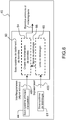
- the figure 4 schematically shows a fourth interferometer 40 comprising a metrology system according to the invention.
- the fourth interferometer 40 represented on the figure 4 resumes the principles of operation of the first interferometer 1, represented on the figure 1 .
- the metrology system according to the invention can also be applied to different two-armed interferometers using overhead projectors and in particular the second and third interferers 20, 30 respectively represented on the figure 2 and on the figure 3 .
- Other examples of interferometers to which the invention can be applied are described in particular in the following work: FOURIER TRANSFORM INFRARED SPECTROMETRY Second Edition - 2007, Publisher: John Wiley and Sons, Authors: Peter R. Griffiths and James A. de Haseth, ⁇ 5.2 tilt-compensated interferometers p.112 to 123 .
- One of the principles of the invention is to use a small number k, greater than or equal to three, metrology laser beams 41 distributed in the field of view, in order to measure and integrate in space, the relative displacements between the first and second retro-reflectors 3, 2.
- the laser beams 41 are represented on the figure 4 by a ray pattern 41.
- the laser beams 41 can form a trihedron if, for example they are three in number.
- An optical device 45 makes it possible to inject the k laser beams 41 into the fourth interferometer 40.
- each laser beam 41 can in particular pass through a laser beam. lambda out of four, or quarter-wave plate, where lambda is the wavelength of the laser, making it possible to obtain with the aid of a polarization splitter, two laser signals 42 in quadrature by laser beam 41, at the output of the interferometer 40.
- the k laser beams 41 are injected in the same direction as the incoming beam 5.
- the k optical beams 41 may be injected into the fourth interferometer 40 in the direction of the first beam 6 for example, according to layout constraints to which the measuring instrument 40 is subjected.
- a deflection mirror 46 pierced with small holes 47, can make a separation at the output of the interferometer between the outgoing science beam 11 and the metrology beam 42 coming out of the fourth interferometer 40.
- the outgoing science beam 11 can be formed from the set of optical rays entering the measuring instrument, coming from a gaseous component to be analyzed, and having passed through the fourth interferometer 40.
- a first convergent lens 43 may converge the science beam 11 to a main detection or acquisition subsystem 44.
- the main detection subsystem 44 outputs interferograms, or science signals 401.
- a science signal represents a analog or digital information from an acquisition at measurement points in the field of view of the fourth interferometer 40.
- a second convergent lens 48 can converge the metrology beam 42 to a secondary detection subsystem 49.
- the converging lens 48 and the subsystem secondary detectors 49 are part of a metrology laser beam acquisition subsystem, hereinafter referred to as the metrology subsystem.
- the secondary detection subsystem 49 outputs k laser signals 400.
- the figure 5 represents an example of injection into the fourth interferometer 40, for k equal to three, of the three laser beams 41 in the field of view observed by the interferometer.
- Each injection position in the field of view corresponds to a single beam direction.
- the direction of the laser beams 41 on the figure 4 is an injection in the center of the field of view.
- the field of view observed by the fourth interferometer 40 may be a sample of the space whose gaseous content is to be analyzed.
- the observed field is measured at different measurement points, said measurement points can be, for example, arranged according to an acquisition matrix 50, represented on the figure 5 .
- a laser beam 51 is said injected on the interferometric axis. For example on figures 1 , 2 , 3 and 4 this amounts to injecting the laser beam 51 along the first axis x.
- a laser beam, injected along the interferometric axis, has a stable apparent wavelength with respect to injection errors.
- a second and a third laser beam 53, 54 may belong to a circle 55 of radius substantially equal to the observed field.
- the equidistance between the first beam 51 and the second and third laser beams 53, 54 makes it possible to favor no particular direction, but this is not an absolutely necessary condition.
- the more the injection positions of the lasers are separated from each other the better the performance of the metrology device according to the invention.
- the second and third laser beams 53, 54 may be arranged so that there is an angle ⁇ of the order of sixty degrees between a first segment 55 joining the first laser beam 51 and the second laser beam 53, and a second segment connecting the first laser beam 51 and the third laser beam 54.
- the angle ⁇ represented on the figure 5 As an example, other angles may be used depending on the application, such as ninety degrees or an angle of one hundred and twenty degrees.
- being able to specify a particular angle makes it possible to improve the performances of the device according to the invention as a function of its different applications.
- the figure 6 represents a data processing subsystem 60 according to the invention.
- the data processing subsystem 60 may be part of a fourth dual arm interferometer 40 using retro-reflectors as described above.
- the data processing subsystem 60 makes it possible to process measurement data originating in particular from a metrology laser beam acquisition subsystem 61.
- the metrology laser beam acquisition subsystem 61 comprises in particular the converging lens 48 and the secondary detecting subsystem 49, as shown in FIG. figure 4 .
- the data processing subsystem 60 further makes it possible to process measurement data 401 from a main science data acquisition subsystem 44, as shown in FIG. figure 4 .
- the metrology subsystem 61, the main acquisition subsystem 44 are in particular measurement outputs.
- the main acquisition subsystem 44 provides, in particular, the scientific interferograms 401 to be studied, to a data processing chain 64 forming part of the data processing subsystem 60.
- an interferogram is an interference measurement. between two waves.
- the metrology subsystem 61 transmits to a metrology unit 65 laser signals 400 representing the measurement of interference of each laser beam 51, 53, 54, as represented for example on the figure 5 after passing through the interferometer 40. With the aid of the laser signals 400, the metrology unit 65 generates metrology signals 66, each representing a reference optical path difference. The reference optical step difference can be transmitted to the data processing chain 64.
- the data processing chain 64 after preprocessing, outputs pre-processed science data to be provided. users of the fourth interferometer 40, as well as metrological data.
- the figure 7 schematically represents several of the steps of the metrology method according to the invention.
- the figure 7 in particular, the metrology unit 65, the data processing subsystem 60 and the processing operations are more particularly described.
- Each laser signal is taken into account by a metrology calculation unit 70, 74, 75 belonging to the metrology unit 65.
- the processes carried out by each metrology calculation unit 70, 74, 75 are independent of one another and detailed later.
- the metrological computing units 70, 74, 75 generate k raw metrology signals 76, i.e., k metrology signals estimated for k distinct points of the field of view.
- the raw k metrology signals 76 are used at the input of a generation unit, or integration unit, of a synthetic metrology per measurement point 71.
- the integration unit of synthetic metrology by measuring point 71 digitally generates synthetic metrology signals 77 for each measuring point, that is to say for each pixel of the matrix 50, represented for example on the figure 5 in the field of view observed by the interferometer 40.
- the synthetic metrology signals generated 77 for each measurement point are then supplied to the data processing chain 64.
- the data processing chain 64 recovers, also the scientific interferograms 401, as represented on the figure 4 .
- the data processing chain 64 can then, depending on the type of interferometer 40 or its use, perform for example a resampling of the scientific interferograms on a fixed metrology grid, then make a Fourier transform of the science data, or make a compression by decimation filtering, or any other radiometric or spectral calibration treatment.
- the figure 8 represents an example of different treatments that can be performed by the metrology calculation units 70, 74, 75 and by the generation unit of a synthetic metrology by measurement point 71, represented on the figure 7 .
- the metrology computing units 70, 74, 75 therefore provide, as shown in FIG. figure 8 for the example, k raw metrology signals 76.
- the k raw metrology signals 76 are then used by the generation unit of a synthetic metrology per measurement point 71 to calculate the optical path difference applicable at each point of measurement. measure for example of the matrix 50.
- the integration unit in the field of view 71 estimates a so-called apex vector, that is to say the vector joining the vertex of the two cube corners 2,3 of the interferometer 40, said cube corners 2, 3 are both projected in the same image space.
- the apex vector is the vector which connects the top of the retro-reflector 3 to the symmetrical vertex of the retro-reflector 2 relative to the splitter plate 4.
- the apex vector estimate uses raw metrology signals 76.
- the linear component of the apex vector is removed.
- the generating unit of a synthetic metrology for measuring point 71 estimates an optical path difference for each measurement point.
- eCCcor t eCC t - eCCx t * 0 eCenterOfFringesY eCenterOfFringesZ
- [eCenterOfFringesY eCenterOfFringesZ] is an estimate of the angular coordinate of the center of the fringes. This estimation can be made for example by linear regression on the vector CC (t).
- One of the advantages of the invention is to generate a metrology that integrates the trajectory in the space of the movable elements of the interferometer, and thus makes it possible to compensate for its defects: in fact, the metrology system according to the invention generates differences in the operation of the laser signals in the field of the interferometer integrating any drifts or vibrations of the movement mechanism of the mobile element or elements of the interferometer.
- the system according to the invention is also robust vis-à-vis a drift injection angles lasers.
- the metrology system makes it possible to correct all the components of the trajectory error: trajectory offset, parabolic component, vibratory effect.
- the system according to the invention notably makes it possible to maintain a stable laser wavelength stable with respect to laser injection.
- the invention also has the advantage of integrating a compensation of a drum skin effect of the separating blade.
- the method according to the invention comprises uncomplicated digital processing enabling real-time processing of the signals.
- the use of the metrology system according to the invention in an interferometer makes it possible to obtain a very high precision in the measurements of the interferometer with an unlimited bandwidth, and no delay.
Landscapes
- Physics & Mathematics (AREA)
- Spectroscopy & Molecular Physics (AREA)
- General Physics & Mathematics (AREA)
- Length Measuring Devices By Optical Means (AREA)
- Instruments For Measurement Of Length By Optical Means (AREA)
- Investigating Or Analysing Materials By Optical Means (AREA)
Applications Claiming Priority (1)
| Application Number | Priority Date | Filing Date | Title |
|---|---|---|---|
| FR1100801A FR2972797B1 (fr) | 2011-03-17 | 2011-03-17 | Systeme et procede de metrologie applique a un interferometre d'analyse a distance d'un compose |
Publications (2)
| Publication Number | Publication Date |
|---|---|
| EP2500701A1 true EP2500701A1 (de) | 2012-09-19 |
| EP2500701B1 EP2500701B1 (de) | 2021-02-17 |
Family
ID=45808351
Family Applications (1)
| Application Number | Title | Priority Date | Filing Date |
|---|---|---|---|
| EP12159489.9A Active EP2500701B1 (de) | 2011-03-17 | 2012-03-14 | Messsystem und -verfahren, das bei einem Interferometer zur Fernanalyse eines gasförmigen Bestandteils angewandt wird |
Country Status (3)
| Country | Link |
|---|---|
| US (1) | US8941836B2 (de) |
| EP (1) | EP2500701B1 (de) |
| FR (1) | FR2972797B1 (de) |
Cited By (2)
| Publication number | Priority date | Publication date | Assignee | Title |
|---|---|---|---|---|
| CN109342350A (zh) * | 2018-12-07 | 2019-02-15 | 中国科学院合肥物质科学研究院 | 一种污染物分布红外光谱扫描成像遥测系统 |
| US11686832B2 (en) * | 2020-07-08 | 2023-06-27 | Commissariat à l'Energie Atomique et aux Energies Alternatives | Ultrasonic target for the purposes of non-destructive inspection |
Families Citing this family (3)
| Publication number | Priority date | Publication date | Assignee | Title |
|---|---|---|---|---|
| JP5519067B1 (ja) * | 2013-11-27 | 2014-06-11 | 株式会社テクノフロント | 光学干渉計、及びこれを用いたフーリエ変換型分光器 |
| CN103674220B (zh) * | 2013-12-30 | 2015-07-15 | 上海理工大学 | 测振系统 |
| DE102018206519B3 (de) * | 2018-04-26 | 2019-07-18 | Bruker Optik Gmbh | Retrointerferometer mit aktiver Nachjustierung |
Citations (2)
| Publication number | Priority date | Publication date | Assignee | Title |
|---|---|---|---|---|
| US4444501A (en) * | 1982-02-12 | 1984-04-24 | The United States Of America As Represented By The Secretary Of Commerce | Stabilization mechanism for optical interferometer |
| US5657122A (en) * | 1995-06-06 | 1997-08-12 | Bio-Rad Laboratories, Inc. | Technique for achieving preferred optical alignment in a scanning interferometer |
Family Cites Families (4)
| Publication number | Priority date | Publication date | Assignee | Title |
|---|---|---|---|---|
| DE3277984D1 (en) * | 1981-03-05 | 1988-02-18 | Ici Plc | Monitoring gaseous pollutants by laser scan |
| US5270790A (en) * | 1990-04-18 | 1993-12-14 | Advantest Corporation | Moving reflector driving part of a Michelson inteferometer |
| US5546185A (en) * | 1994-09-23 | 1996-08-13 | Kabushiki Kaisha Toshiba | Angle detecting apparatus for detecting angle of inclination of scanning mirror provided on michelson interferometer |
| US5671047A (en) * | 1995-05-15 | 1997-09-23 | Bio-Rad Laboratories | Laser beamsplitter for generating a plurality of parallel beams |
-
2011
- 2011-03-17 FR FR1100801A patent/FR2972797B1/fr active Active
-
2012
- 2012-03-14 EP EP12159489.9A patent/EP2500701B1/de active Active
- 2012-03-15 US US13/421,736 patent/US8941836B2/en active Active
Patent Citations (2)
| Publication number | Priority date | Publication date | Assignee | Title |
|---|---|---|---|---|
| US4444501A (en) * | 1982-02-12 | 1984-04-24 | The United States Of America As Represented By The Secretary Of Commerce | Stabilization mechanism for optical interferometer |
| US5657122A (en) * | 1995-06-06 | 1997-08-12 | Bio-Rad Laboratories, Inc. | Technique for achieving preferred optical alignment in a scanning interferometer |
Non-Patent Citations (1)
| Title |
|---|
| PETER R. GRIFFITHS; JAMES A. DE HASETH: "FOURIER TRANSFORM INFRARED SPECTROMETRY", 2007, JOHN WILEY AND SONS, pages: 112 - 123 |
Cited By (2)
| Publication number | Priority date | Publication date | Assignee | Title |
|---|---|---|---|---|
| CN109342350A (zh) * | 2018-12-07 | 2019-02-15 | 中国科学院合肥物质科学研究院 | 一种污染物分布红外光谱扫描成像遥测系统 |
| US11686832B2 (en) * | 2020-07-08 | 2023-06-27 | Commissariat à l'Energie Atomique et aux Energies Alternatives | Ultrasonic target for the purposes of non-destructive inspection |
Also Published As
| Publication number | Publication date |
|---|---|
| US8941836B2 (en) | 2015-01-27 |
| FR2972797B1 (fr) | 2019-12-13 |
| EP2500701B1 (de) | 2021-02-17 |
| US20130044327A1 (en) | 2013-02-21 |
| FR2972797A1 (fr) | 2012-09-21 |
Similar Documents
| Publication | Publication Date | Title |
|---|---|---|
| US8786864B2 (en) | Circular common-path point diffraction interference wavefront sensor | |
| JP6364551B2 (ja) | 干渉計 | |
| US7773229B2 (en) | Doppler asymmetric spatial heterodyne spectroscopy | |
| EP2500701B1 (de) | Messsystem und -verfahren, das bei einem Interferometer zur Fernanalyse eines gasförmigen Bestandteils angewandt wird | |
| WO2005052502A2 (en) | Pixelated phase-mask interferometer | |
| CN104568152A (zh) | 横向剪切干涉扫描傅里叶变换成像光谱仪 | |
| CN106537104A (zh) | 用于光束表征的设备和方法 | |
| CN103727901A (zh) | 基于波长移相法检测平面间平行度的方法 | |
| US10054419B2 (en) | Method for analyzing an object using a combination of long and short coherence interferometry | |
| US10281258B2 (en) | Lensless imaging with reduced aperture | |
| US20190271534A1 (en) | Lensless imaging with reduced aperture | |
| CN113029526B (zh) | 一种综合孔径共相误差估计方法及装置 | |
| JP2021032661A (ja) | 干渉計 | |
| JP2011516847A (ja) | 二次元サンプリングのための小型分光器 | |
| FR2947049B1 (fr) | Systeme et procede d'interferometrie statique | |
| CN115575098B (zh) | 一种空间望远镜结构稳定性在轨测试方法和系统 | |
| WO2008046998A1 (fr) | Procédé de correction d'un analyseur de front d'onde, et analyseur implémentant ce procédé | |
| US12546582B2 (en) | Rapid coherent synthetic wavelength interferometric absolute distance measurement | |
| CN109780991B (zh) | 基于误差分离的光学非线性一阶误差补偿方法及装置 | |
| CN113447125B (zh) | 一种多分辨率模式干涉光谱系统 | |
| US7701583B2 (en) | Coherence spectrometry devices | |
| Bernier et al. | Technical improvements and performances of SpIOMM: an imaging Fourier transform spectrometer for astronomy | |
| CA3037110A1 (fr) | Procede et dispositif d'analyse d'une onde electromagnetique en haute definition | |
| EP2176633A2 (de) | Verfahren zur schätzung mindestens einer deformation der wellenfront eines optischen systems oder eines durch das optische system beobachteten objekts und diesbezügliche einrichtung | |
| CN119879720B (zh) | 一种基于sd-oct技术的k域均匀化和色散补偿方法 |
Legal Events
| Date | Code | Title | Description |
|---|---|---|---|
| PUAI | Public reference made under article 153(3) epc to a published international application that has entered the european phase |
Free format text: ORIGINAL CODE: 0009012 |
|
| AK | Designated contracting states |
Kind code of ref document: A1 Designated state(s): AL AT BE BG CH CY CZ DE DK EE ES FI FR GB GR HR HU IE IS IT LI LT LU LV MC MK MT NL NO PL PT RO RS SE SI SK SM TR |
|
| AX | Request for extension of the european patent |
Extension state: BA ME |
|
| 17P | Request for examination filed |
Effective date: 20130305 |
|
| STAA | Information on the status of an ep patent application or granted ep patent |
Free format text: STATUS: EXAMINATION IS IN PROGRESS |
|
| 17Q | First examination report despatched |
Effective date: 20200107 |
|
| GRAP | Despatch of communication of intention to grant a patent |
Free format text: ORIGINAL CODE: EPIDOSNIGR1 |
|
| STAA | Information on the status of an ep patent application or granted ep patent |
Free format text: STATUS: GRANT OF PATENT IS INTENDED |
|
| INTG | Intention to grant announced |
Effective date: 20201202 |
|
| GRAS | Grant fee paid |
Free format text: ORIGINAL CODE: EPIDOSNIGR3 |
|
| GRAA | (expected) grant |
Free format text: ORIGINAL CODE: 0009210 |
|
| STAA | Information on the status of an ep patent application or granted ep patent |
Free format text: STATUS: THE PATENT HAS BEEN GRANTED |
|
| AK | Designated contracting states |
Kind code of ref document: B1 Designated state(s): AL AT BE BG CH CY CZ DE DK EE ES FI FR GB GR HR HU IE IS IT LI LT LU LV MC MK MT NL NO PL PT RO RS SE SI SK SM TR |
|
| RAP1 | Party data changed (applicant data changed or rights of an application transferred) |
Owner name: THALES |
|
| REG | Reference to a national code |
Ref country code: GB Ref legal event code: FG4D Free format text: NOT ENGLISH |
|
| REG | Reference to a national code |
Ref country code: CH Ref legal event code: EP |
|
| REG | Reference to a national code |
Ref country code: DE Ref legal event code: R096 Ref document number: 602012074351 Country of ref document: DE |
|
| REG | Reference to a national code |
Ref country code: AT Ref legal event code: REF Ref document number: 1362049 Country of ref document: AT Kind code of ref document: T Effective date: 20210315 Ref country code: CH Ref legal event code: NV Representative=s name: SERVOPATENT GMBH, CH |
|
| REG | Reference to a national code |
Ref country code: IE Ref legal event code: FG4D Free format text: LANGUAGE OF EP DOCUMENT: FRENCH |
|
| REG | Reference to a national code |
Ref country code: LT Ref legal event code: MG9D |
|
| REG | Reference to a national code |
Ref country code: NL Ref legal event code: MP Effective date: 20210217 |
|
| PG25 | Lapsed in a contracting state [announced via postgrant information from national office to epo] |
Ref country code: NO Free format text: LAPSE BECAUSE OF FAILURE TO SUBMIT A TRANSLATION OF THE DESCRIPTION OR TO PAY THE FEE WITHIN THE PRESCRIBED TIME-LIMIT Effective date: 20210517 Ref country code: BG Free format text: LAPSE BECAUSE OF FAILURE TO SUBMIT A TRANSLATION OF THE DESCRIPTION OR TO PAY THE FEE WITHIN THE PRESCRIBED TIME-LIMIT Effective date: 20210517 Ref country code: HR Free format text: LAPSE BECAUSE OF FAILURE TO SUBMIT A TRANSLATION OF THE DESCRIPTION OR TO PAY THE FEE WITHIN THE PRESCRIBED TIME-LIMIT Effective date: 20210217 Ref country code: FI Free format text: LAPSE BECAUSE OF FAILURE TO SUBMIT A TRANSLATION OF THE DESCRIPTION OR TO PAY THE FEE WITHIN THE PRESCRIBED TIME-LIMIT Effective date: 20210217 Ref country code: GR Free format text: LAPSE BECAUSE OF FAILURE TO SUBMIT A TRANSLATION OF THE DESCRIPTION OR TO PAY THE FEE WITHIN THE PRESCRIBED TIME-LIMIT Effective date: 20210518 Ref country code: LT Free format text: LAPSE BECAUSE OF FAILURE TO SUBMIT A TRANSLATION OF THE DESCRIPTION OR TO PAY THE FEE WITHIN THE PRESCRIBED TIME-LIMIT Effective date: 20210217 Ref country code: PT Free format text: LAPSE BECAUSE OF FAILURE TO SUBMIT A TRANSLATION OF THE DESCRIPTION OR TO PAY THE FEE WITHIN THE PRESCRIBED TIME-LIMIT Effective date: 20210617 |
|
| REG | Reference to a national code |
Ref country code: AT Ref legal event code: MK05 Ref document number: 1362049 Country of ref document: AT Kind code of ref document: T Effective date: 20210217 |
|
| PG25 | Lapsed in a contracting state [announced via postgrant information from national office to epo] |
Ref country code: SE Free format text: LAPSE BECAUSE OF FAILURE TO SUBMIT A TRANSLATION OF THE DESCRIPTION OR TO PAY THE FEE WITHIN THE PRESCRIBED TIME-LIMIT Effective date: 20210217 Ref country code: NL Free format text: LAPSE BECAUSE OF FAILURE TO SUBMIT A TRANSLATION OF THE DESCRIPTION OR TO PAY THE FEE WITHIN THE PRESCRIBED TIME-LIMIT Effective date: 20210217 Ref country code: PL Free format text: LAPSE BECAUSE OF FAILURE TO SUBMIT A TRANSLATION OF THE DESCRIPTION OR TO PAY THE FEE WITHIN THE PRESCRIBED TIME-LIMIT Effective date: 20210217 Ref country code: LV Free format text: LAPSE BECAUSE OF FAILURE TO SUBMIT A TRANSLATION OF THE DESCRIPTION OR TO PAY THE FEE WITHIN THE PRESCRIBED TIME-LIMIT Effective date: 20210217 Ref country code: RS Free format text: LAPSE BECAUSE OF FAILURE TO SUBMIT A TRANSLATION OF THE DESCRIPTION OR TO PAY THE FEE WITHIN THE PRESCRIBED TIME-LIMIT Effective date: 20210217 |
|
| PG25 | Lapsed in a contracting state [announced via postgrant information from national office to epo] |
Ref country code: IS Free format text: LAPSE BECAUSE OF FAILURE TO SUBMIT A TRANSLATION OF THE DESCRIPTION OR TO PAY THE FEE WITHIN THE PRESCRIBED TIME-LIMIT Effective date: 20210617 |
|
| PG25 | Lapsed in a contracting state [announced via postgrant information from national office to epo] |
Ref country code: SM Free format text: LAPSE BECAUSE OF FAILURE TO SUBMIT A TRANSLATION OF THE DESCRIPTION OR TO PAY THE FEE WITHIN THE PRESCRIBED TIME-LIMIT Effective date: 20210217 Ref country code: AT Free format text: LAPSE BECAUSE OF FAILURE TO SUBMIT A TRANSLATION OF THE DESCRIPTION OR TO PAY THE FEE WITHIN THE PRESCRIBED TIME-LIMIT Effective date: 20210217 Ref country code: CZ Free format text: LAPSE BECAUSE OF FAILURE TO SUBMIT A TRANSLATION OF THE DESCRIPTION OR TO PAY THE FEE WITHIN THE PRESCRIBED TIME-LIMIT Effective date: 20210217 Ref country code: EE Free format text: LAPSE BECAUSE OF FAILURE TO SUBMIT A TRANSLATION OF THE DESCRIPTION OR TO PAY THE FEE WITHIN THE PRESCRIBED TIME-LIMIT Effective date: 20210217 |
|
| REG | Reference to a national code |
Ref country code: DE Ref legal event code: R097 Ref document number: 602012074351 Country of ref document: DE |
|
| PG25 | Lapsed in a contracting state [announced via postgrant information from national office to epo] |
Ref country code: MC Free format text: LAPSE BECAUSE OF FAILURE TO SUBMIT A TRANSLATION OF THE DESCRIPTION OR TO PAY THE FEE WITHIN THE PRESCRIBED TIME-LIMIT Effective date: 20210217 Ref country code: ES Free format text: LAPSE BECAUSE OF FAILURE TO SUBMIT A TRANSLATION OF THE DESCRIPTION OR TO PAY THE FEE WITHIN THE PRESCRIBED TIME-LIMIT Effective date: 20210217 Ref country code: DK Free format text: LAPSE BECAUSE OF FAILURE TO SUBMIT A TRANSLATION OF THE DESCRIPTION OR TO PAY THE FEE WITHIN THE PRESCRIBED TIME-LIMIT Effective date: 20210217 Ref country code: SK Free format text: LAPSE BECAUSE OF FAILURE TO SUBMIT A TRANSLATION OF THE DESCRIPTION OR TO PAY THE FEE WITHIN THE PRESCRIBED TIME-LIMIT Effective date: 20210217 Ref country code: RO Free format text: LAPSE BECAUSE OF FAILURE TO SUBMIT A TRANSLATION OF THE DESCRIPTION OR TO PAY THE FEE WITHIN THE PRESCRIBED TIME-LIMIT Effective date: 20210217 |
|
| REG | Reference to a national code |
Ref country code: BE Ref legal event code: MM Effective date: 20210331 |
|
| PLBE | No opposition filed within time limit |
Free format text: ORIGINAL CODE: 0009261 |
|
| STAA | Information on the status of an ep patent application or granted ep patent |
Free format text: STATUS: NO OPPOSITION FILED WITHIN TIME LIMIT |
|
| 26N | No opposition filed |
Effective date: 20211118 |
|
| PG25 | Lapsed in a contracting state [announced via postgrant information from national office to epo] |
Ref country code: IE Free format text: LAPSE BECAUSE OF NON-PAYMENT OF DUE FEES Effective date: 20210314 Ref country code: LU Free format text: LAPSE BECAUSE OF NON-PAYMENT OF DUE FEES Effective date: 20210314 Ref country code: AL Free format text: LAPSE BECAUSE OF FAILURE TO SUBMIT A TRANSLATION OF THE DESCRIPTION OR TO PAY THE FEE WITHIN THE PRESCRIBED TIME-LIMIT Effective date: 20210217 |
|
| PG25 | Lapsed in a contracting state [announced via postgrant information from national office to epo] |
Ref country code: SI Free format text: LAPSE BECAUSE OF FAILURE TO SUBMIT A TRANSLATION OF THE DESCRIPTION OR TO PAY THE FEE WITHIN THE PRESCRIBED TIME-LIMIT Effective date: 20210217 |
|
| PG25 | Lapsed in a contracting state [announced via postgrant information from national office to epo] |
Ref country code: IS Free format text: LAPSE BECAUSE OF FAILURE TO SUBMIT A TRANSLATION OF THE DESCRIPTION OR TO PAY THE FEE WITHIN THE PRESCRIBED TIME-LIMIT Effective date: 20210617 |
|
| PG25 | Lapsed in a contracting state [announced via postgrant information from national office to epo] |
Ref country code: BE Free format text: LAPSE BECAUSE OF NON-PAYMENT OF DUE FEES Effective date: 20210331 |
|
| PG25 | Lapsed in a contracting state [announced via postgrant information from national office to epo] |
Ref country code: HU Free format text: LAPSE BECAUSE OF FAILURE TO SUBMIT A TRANSLATION OF THE DESCRIPTION OR TO PAY THE FEE WITHIN THE PRESCRIBED TIME-LIMIT; INVALID AB INITIO Effective date: 20120314 Ref country code: CY Free format text: LAPSE BECAUSE OF FAILURE TO SUBMIT A TRANSLATION OF THE DESCRIPTION OR TO PAY THE FEE WITHIN THE PRESCRIBED TIME-LIMIT Effective date: 20210217 |
|
| PG25 | Lapsed in a contracting state [announced via postgrant information from national office to epo] |
Ref country code: MK Free format text: LAPSE BECAUSE OF FAILURE TO SUBMIT A TRANSLATION OF THE DESCRIPTION OR TO PAY THE FEE WITHIN THE PRESCRIBED TIME-LIMIT Effective date: 20210217 |
|
| PG25 | Lapsed in a contracting state [announced via postgrant information from national office to epo] |
Ref country code: TR Free format text: LAPSE BECAUSE OF FAILURE TO SUBMIT A TRANSLATION OF THE DESCRIPTION OR TO PAY THE FEE WITHIN THE PRESCRIBED TIME-LIMIT Effective date: 20210217 |
|
| PG25 | Lapsed in a contracting state [announced via postgrant information from national office to epo] |
Ref country code: MT Free format text: LAPSE BECAUSE OF FAILURE TO SUBMIT A TRANSLATION OF THE DESCRIPTION OR TO PAY THE FEE WITHIN THE PRESCRIBED TIME-LIMIT Effective date: 20210217 |
|
| PGFP | Annual fee paid to national office [announced via postgrant information from national office to epo] |
Ref country code: DE Payment date: 20250218 Year of fee payment: 14 |
|
| PGFP | Annual fee paid to national office [announced via postgrant information from national office to epo] |
Ref country code: FR Payment date: 20250224 Year of fee payment: 14 |
|
| PGFP | Annual fee paid to national office [announced via postgrant information from national office to epo] |
Ref country code: IT Payment date: 20250226 Year of fee payment: 14 Ref country code: GB Payment date: 20250213 Year of fee payment: 14 |
|
| PGFP | Annual fee paid to national office [announced via postgrant information from national office to epo] |
Ref country code: CH Payment date: 20250401 Year of fee payment: 14 |