EP2500680A1 - Vapor cooling heat exchanger - Google Patents
Vapor cooling heat exchanger Download PDFInfo
- Publication number
- EP2500680A1 EP2500680A1 EP10829883A EP10829883A EP2500680A1 EP 2500680 A1 EP2500680 A1 EP 2500680A1 EP 10829883 A EP10829883 A EP 10829883A EP 10829883 A EP10829883 A EP 10829883A EP 2500680 A1 EP2500680 A1 EP 2500680A1
- Authority
- EP
- European Patent Office
- Prior art keywords
- fin
- target fluid
- cooling target
- refrigerant
- passage
- Prior art date
- Legal status (The legal status is an assumption and is not a legal conclusion. Google has not performed a legal analysis and makes no representation as to the accuracy of the status listed.)
- Withdrawn
Links
Images




Classifications
-
- F—MECHANICAL ENGINEERING; LIGHTING; HEATING; WEAPONS; BLASTING
- F28—HEAT EXCHANGE IN GENERAL
- F28D—HEAT-EXCHANGE APPARATUS, NOT PROVIDED FOR IN ANOTHER SUBCLASS, IN WHICH THE HEAT-EXCHANGE MEDIA DO NOT COME INTO DIRECT CONTACT
- F28D9/00—Heat-exchange apparatus having stationary plate-like or laminated conduit assemblies for both heat-exchange media, the media being in contact with different sides of a conduit wall
- F28D9/02—Heat-exchange apparatus having stationary plate-like or laminated conduit assemblies for both heat-exchange media, the media being in contact with different sides of a conduit wall the heat-exchange media travelling at an angle to one another
-
- F—MECHANICAL ENGINEERING; LIGHTING; HEATING; WEAPONS; BLASTING
- F28—HEAT EXCHANGE IN GENERAL
- F28D—HEAT-EXCHANGE APPARATUS, NOT PROVIDED FOR IN ANOTHER SUBCLASS, IN WHICH THE HEAT-EXCHANGE MEDIA DO NOT COME INTO DIRECT CONTACT
- F28D9/00—Heat-exchange apparatus having stationary plate-like or laminated conduit assemblies for both heat-exchange media, the media being in contact with different sides of a conduit wall
- F28D9/0062—Heat-exchange apparatus having stationary plate-like or laminated conduit assemblies for both heat-exchange media, the media being in contact with different sides of a conduit wall the conduits for one heat-exchange medium being formed by spaced plates with inserted elements
-
- F—MECHANICAL ENGINEERING; LIGHTING; HEATING; WEAPONS; BLASTING
- F28—HEAT EXCHANGE IN GENERAL
- F28F—DETAILS OF HEAT-EXCHANGE AND HEAT-TRANSFER APPARATUS, OF GENERAL APPLICATION
- F28F13/00—Arrangements for modifying heat-transfer, e.g. increasing, decreasing
- F28F13/02—Arrangements for modifying heat-transfer, e.g. increasing, decreasing by influencing fluid boundary
-
- F—MECHANICAL ENGINEERING; LIGHTING; HEATING; WEAPONS; BLASTING
- F28—HEAT EXCHANGE IN GENERAL
- F28F—DETAILS OF HEAT-EXCHANGE AND HEAT-TRANSFER APPARATUS, OF GENERAL APPLICATION
- F28F13/00—Arrangements for modifying heat-transfer, e.g. increasing, decreasing
- F28F13/14—Arrangements for modifying heat-transfer, e.g. increasing, decreasing by endowing the walls of conduits with zones of different degrees of conduction of heat
-
- F—MECHANICAL ENGINEERING; LIGHTING; HEATING; WEAPONS; BLASTING
- F28—HEAT EXCHANGE IN GENERAL
- F28F—DETAILS OF HEAT-EXCHANGE AND HEAT-TRANSFER APPARATUS, OF GENERAL APPLICATION
- F28F3/00—Plate-like or laminated elements; Assemblies of plate-like or laminated elements
- F28F3/08—Elements constructed for building-up into stacks, e.g. capable of being taken apart for cleaning
Definitions
- the second fin is arranged in an upstream portion of the cooling target fluid passage in the flow direction of the cooling target fluid where the local heat flux of the partition wall increases.
- the cooling target fluid passage and the refrigerant passage are arranged side by side such that the flow direction of the cooling target fluid and the flow direction of the refrigerant cross each other.
- the second fin is arranged in an upstream portion of the cooling target fluid passage in the flow direction of the cooling target fluid that is a zone in the cooling target fluid passage that corresponds to a downstream portion of the refrigerant passage in the flow direction of the refrigerant.
- each second fin 30 is arranged in the downstream portion 21b of the associated cooling target fluid passage 21, which is a zone corresponding to the downstream portion 24b of the refrigerant passage 24.
- the second embodiment has the same advantage as the advantage (1) of the first embodiment.
- each second fin 30 is greater than the thickness L2 of each first fin 31.
- the present invention is not restricted to this configuration.
- the second fin 30 and the first fin 31 may have the same thickness.
- brazing filler R1 is supplied into the gap between each corner portion 30b of the second fin 30 and the corresponding partition wall 19 by an amount greater than the amount of the brazing filler R1 used in the gap between each corner portion 31 b of the first fin 31 and the corresponding partition wall 19. In this manner, the contact area by which the base portion of each second fin 30 is held in contact with the brazing filler R1 is increased.
Landscapes
- Engineering & Computer Science (AREA)
- Physics & Mathematics (AREA)
- Thermal Sciences (AREA)
- Mechanical Engineering (AREA)
- General Engineering & Computer Science (AREA)
- Exhaust-Gas Circulating Devices (AREA)
- Heat-Exchange Devices With Radiators And Conduit Assemblies (AREA)
Abstract
Description
- The present invention relates to an vapor cooling heat exchanger.
- Typically, a heat exchanger for an vapor cooling apparatus includes a cooling target fluid passage, in which cooling target fluid flows, and a refrigerant passage, in which liquid refrigerant for cooling the cooling target fluid flows. Heat exchange is brought about between the cooling target fluid passage and the refrigerant passage through a partition wall. In the heat exchanger, the liquid refrigerant flowing in the refrigerant passage cools the partition wall, which has been heated by the cooling target fluid, and is thus heated. When the temperature of the heat transmitting surface of the partition wall exceeds the saturation temperature of the liquid refrigerant, nucleate boiling, in which generation and departure of bubbles are repeated, is initiated on the wall surface of the partition wall. The cooling target fluid flowing in the cooling target fluid passage is thus cooled by using the boiling vaporization latent heat produced through the nucleate boiling. One such type of heat exchanger for an vapor cooling apparatus is disclosed in, for example, Patent Document 1.
- Patent Document 1 describes a plate fin type exhaust gas heat exchanger. The exhaust gas heat exchanger is configured by a necessary number of layers each including a fluid passage having a corrugated fin for increasing a heat transmission surface area. The layers are arranged between a pair of tube plates, which are partition walls, having a pair of spacer bars that close opposite sides of the tube plates. In the exhaust gas heat exchanger, high-temperature fluid (cooling target fluid) and low-temperature fluid (liquid refrigerant) enter separate fluid passages through adjacent side surfaces. Heat exchange is thus caused between the high-temperature fluid and the low-temperature fluid through the tube plates and the corrugated fins. Meanwhile, vapor cooling is carried out.
-
- Patent Document 1: Japanese Laid-Open Utility Model Publication No.
3-79070 - However, in the exhaust gas heat exchanger described in Patent Document 1, heat flux in the fluid passage in which the high-temperature fluid flows locally increases in a contact portion of each tube plate that contacts the corresponding corrugated fin. This promotes boiling of the low-temperature fluid at the position corresponding to the contact portion, where the heat flux locally increases, in the fluid passage in which the low-temperature fluid flows. As a result, film boiling may occur and cover each tube plate with a bubble film, thus causing a burnout. This causes dryness in the fluid passage in which the low-temperature fluid flows at the position corresponding to the contact portion and decreases cooling performance of the heat exchanger.
- Accordingly, it is an objective of the present invention to prevent local burnout in an vapor cooling heat exchanger having a fin arranged in a cooling target fluid passage.
- In accordance with one aspect of the present invention, an vapor cooling heat exchanger that includes a partition wall and a fin is provided. The partition wall separates a cooling target fluid passage, in which cooling target fluid flows, from a refrigerant passage, in which refrigerant for cooling the cooling target fluid flows. The fin is arranged in the cooling target fluid passage and thermally connected to the partition wall. The fin includes a first fin and a second fin. The second fin decreases a local heat flux of the partition wall by a greater degree than the first fin does. The first fin and the second fin are arranged based on the relationship between the local heat flux of the partition wall and the critical heat flux of the refrigerant.
- In accordance with one aspect, the thickness of the second fin is greater than the thickness of the first fin.
- In accordance with another aspect, the second fin is arranged in an upstream portion of the cooling target fluid passage in the flow direction of the cooling target fluid where the local heat flux of the partition wall increases.
- In accordance with a further aspect, the second fin is arranged in a zone of the cooling target fluid passage that corresponds to a downstream portion of the refrigerant passage in the flow direction of the refrigerant where the critical heat flux decreases.
- Also, in accordance with another aspect, the cooling target fluid passage and the refrigerant passage are arranged side by side such that the flow direction of the cooling target fluid and the flow direction of the refrigerant cross each other. The second fin is arranged in an upstream portion of the cooling target fluid passage in the flow direction of the cooling target fluid that is a zone in the cooling target fluid passage that corresponds to a downstream portion of the refrigerant passage in the flow direction of the refrigerant.
-
-
Fig. 1 is a perspective view schematically showing an vapor cooling heat exchanger according to a first embodiment of the present invention; -
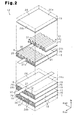
Fig. 2 is an exploded perspective view showing a heat exchanging portion of the heat exchanger illustrated inFig. 1 ; -
Fig. 3A is a vertical cross-sectional view showing a second fin; -
Fig. 3B is a vertical cross-sectional view showing a first fin; -
Fig. 4 is a graph representing the relationship between positions in the flow directions in a cooling target fluid passage and the flow direction in a refrigerant passage and heat flux in the first embodiment; -
Fig. 5 is an exploded perspective view showing a portion of a heat exchanging portion of a second embodiment; -
Fig. 6 is a graph representing the relationship between positions in the flow direction in a cooling target fluid passage and the flow direction in a refrigerant passage and heat flux in the second embodiment; -
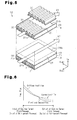
Fig. 7 is an exploded perspective view showing a portion of a heat exchanging portion of a third embodiment; -
Fig. 8 is a graph representing the relationship between positions in the flow direction in a cooling target fluid passage and heat flux in the third embodiment; -
Fig. 9 is an exploded perspective view showing a portion of a heat exchanging portion of another embodiment; -
Fig. 10 is a graph representing the relationship between positions in the flow direction in a cooling target fluid passage and the flow direction in a refrigerant passage and heat flux in the embodiment illustrated inFig. 9 ; -
Fig. 11 is an exploded perspective view showing a portion of a heat exchanging portion of another embodiment; and -
Fig. 12 is a graph representing the relationship between positions in the flow direction in a cooling target fluid passage and the flow direction in a refrigerant passage and heat flux in the embodiment illustrated inFig. 11 . - An vapor cooling heat exchanger (hereinafter, referred to simply as a heat exchanger) for an EGR (exhaust gas recirculation) gas vapor cooling device (an EGR cooler) used in an EGR apparatus for vehicles will now be described with reference to
Figs. 1 to 4 . Theheat exchanger 11 for the EGR apparatus causes heat exchange between EGR gas serving as cooling target fluid and water (liquid refrigerant) serving as refrigerant, thus boiling some of the water to cool the EGR gas. For the description below, a "forward-rearward direction", an "upward-downward direction", and a "leftward-rightward direction" are defined as represented by the corresponding arrows inFig. 1 , unless otherwise specified. - As shown in
Fig. 1 , aheat exchanging portion 12 is received in a substantially rectangular box-like housing 11a, which configures an outer casing for theheat exchanger 11. In the housing 11a, a cooling targetfluid inlet portion 14 is arranged forward of theheat exchanging portion 12. A cooling targetfluid outlet portion 15 is arranged rearward of theheat exchanging portion 12. - An
inlet pipe 16 for introducing EGR gas into the cooling targetfluid inlet portion 14 is connected to the front surface of the housing 11a. Anoutlet pipe 17 for discharging the EGR gas out from the cooling targetfluid outlet portion 15 is connected to the rear surface of the housing 11a. Theheat exchanger 11 is used with theinlet pipe 16 connected to the inlet of an EGR passage and theoutlet pipe 17 connected to the outlet of the EGR passage. -
First ends 22a of arefrigerant inlet pipe 22, which introduces water into theheat exchanging portion 12 of the housing 11 a, are drawn into the housing 11 a through the right surface of the housing 11 a, which is one of the opposite surfaces located between the front and rear surfaces. Also,first ends 23a of arefrigerant outlet pipe 23, which discharge water out from theheat exchanging portion 12, are drawn into the housing 11a through the left surface of the housing 11 a, which is the other one of the opposite surfaces located between the front and rear surfaces. - With reference to
Fig. 2 , theheat exchanging portion 12 includes a plurality of (in the first embodiment, three)passage defining bodies 18. Each of thepassage defining bodies 18 is configured by afirst fin 31 and asecond fin 30, which are arranged between twoflat partition walls 19. A pair of spacer bars 20 close opposite sides of thepartition walls 19. As illustrated inFig. 1 , theheat exchanging portion 12 includes afront wall 13a joined to the front opening ends of thepassage defining bodies 18 and arear wall 13b joined to the rear opening ends of thepassage defining bodies 18. Thepassage defining bodies 18 are joined to thefront wall 13a and therear wall 13b such that thecorresponding partition walls 19 of the adjacent pairs of thepassage defining bodies 18 are spaced apart at uniform intervals. - The front opening of each
passage defining body 18 is arranged on the side corresponding to the cooling targetfluid inlet portion 14 and the rear opening of thepassage defining body 18 is located on the side corresponding to the cooling targetfluid outlet portion 15. Thefront wall 13a has elongatedholes 13e, which are formed at positions corresponding to thepassage defining bodies 18 to allow communication between the interior of the cooling targetfluid inlet portion 14 and the front openings of the correspondingpassage defining bodies 18. Therear wall 13b has elongated holes (not shown) formed at positions corresponding to thepassage defining bodies 18 to allow communication between the interior of the cooling targetfluid outlet portion 15 and the rear openings of the correspondingpassage defining bodies 18. - After flowing from the
inlet pipe 16 into the cooling targetfluid inlet portion 14, EGR gas enters thepassage defining bodies 18 from the front openings through the correspondingelongated holes 13e in thefront wall 13a. The EGR gas flows out from the rear openings into the cooling targetfluid outlet portion 15 through the corresponding elongated holes in therear wall 13b. The EGR gas is then directed to the outlet of the EGR passage through theoutlet pipe 17. As a result, with reference toFig. 2 , the interior of eachpassage defining body 18 forms a coolingtarget fluid passage 21, in which EGR gas flows. - The front opening of each one of the
passage defining bodies 18 is the inlet for EGR gas into the corresponding coolingtarget fluid passage 21. The portion corresponding to the inlet of eachpassage defining body 18 is anupstream portion 21 a of each of the corresponding coolingtarget fluid passage 21 in the flow direction of the EGR gas (as represented by arrow X1 inFig. 2 ). The rear opening of eachpassage defining body 18 is the outlet for the EGR gas from the corresponding coolingtarget fluid passage 21. The portion corresponding to the outlet of eachpassage defining body 18 is adownstream portion 21 b of each of the corresponding coolingtarget fluid passage 21 in the flow direction of the EGR gas. In the first embodiment, the "upstream portion 21 a of each coolingtarget fluid passage 21" refers to a zone close to the inlet with respect to a middle portion in the flow direction in the coolingtarget fluid passage 21. The "downstream portion 21b of each coolingtarget fluid passage 21" refers to a zone close to the outlet with respect to the middle portion in the flow direction in the coolingtarget fluid passage 21. - In the
heat exchanging portion 12, arefrigerant passage 24 is defined between the opposingpartition walls 19 of each adjacent pair of thepassage defining bodies 18. As shown inFig. 1 , the front opening of eachrefrigerant passage 24 communicates with the corresponding one of the first ends 23a of therefrigerant outlet pipe 23 through a hole formed in thefront wall 13a. The rear opening of therefrigerant passage 24 communicates with the corresponding one of the first ends 22a of therefrigerant inlet pipe 22 through ahole 13c formed in therear wall 13b. The opposite sides of eachrefrigerant passage 24 perpendicular to thefront wall 13a and therear wall 13b are closed by the left and right surfaces of the housing 11 a. - The first ends 23a of the
refrigerant outlet pipe 23 face the front openings of the correspondingrefrigerant passages 24. The first ends 22a of therefrigerant inlet pipe 22 face the rear openings of the correspondingrefrigerant passages 24. A second end of therefrigerant inlet pipe 22 is connected to a first end of a water circulation pipe (not shown) and a second end of therefrigerant outlet pipe 23 is connected to a second end of the circulation pipe. Water is thus introduced into therefrigerant passages 24 through the corresponding first ends 22a of therefrigerant inlet pipe 22. The water is then passed through therefrigerant passages 24 and discharged through the first ends 23a of therefrigerant outlet pipe 23 to return to the circulation pipe. - The rear opening of each
refrigerant passage 24, which faces the correspondingfirst end 22a of therefrigerant inlet pipe 22, is the inlet into therefrigerant passage 24. The inlet portion of therefrigerant passage 24 is anupstream portion 24a of therefrigerant passage 24 in the water flow direction (represented by arrow X2 inFig. 2 ). The front opening of eachrefrigerant passage 24, which faces the correspondingfirst end 23a of therefrigerant outlet pipe 23, is the outlet from therefrigerant passage 24. The outlet portion of therefrigerant passage 24 is adownstream portion 24b of therefrigerant passage 24 in the water flow direction. In the first embodiment, the "upstream portion 24a of eachrefrigerant passage 24" refers to a zone close to the inlet with respect to a middle portion in the flow direction in therefrigerant passage 24. The "downstream portion 24b of eachrefrigerant passage 24" refers to a zone close to the outlet with respect to the middle portion in the flow direction in therefrigerant passage 24. - In the
heat exchanging portion 12, each coolingtarget fluid passage 21 and the adjacentrefrigerant passage 24 are arranged side by side in the manner described below. Specifically, the inlet of therefrigerant passage 24 is arranged at the positions corresponding to the position of the outlet of the coolingtarget fluid passage 21 in the direction in which thepassage defining bodies 18 are laminated. The position of the outlet of therefrigerant passage 24 corresponds to the position of the inlet of the coolingtarget fluid passage 21 in the lamination direction of thepassage defining bodies 18. As a result, in theheat exchanger 11 of the first embodiment, EGR gas and water form opposite flows, or, in other words, the flow direction of the EGR gas and the flow direction of the water are opposite to each other. Each of thepartition walls 19, which form the correspondingpassage defining body 18, separates the corresponding coolingtarget fluid passage 21 from the adjacentrefrigerant passage 24. -
Fig. 4 is a graph representing the relationship between the positions in the flow direction in the coolingtarget fluid passage 21 and the flow direction in the refrigerant passage 24 (the axis of abscissas) and the heat flux (the axis of ordinates). The line formed by a long dash alternating with two short dashes represents the local heat flux in a portion of eachpartition wall 19 thermally connected to a corresponding conventional fin in a case in which conventional fin having equal thicknesses over the entire zone (from the upstream portion to the downstream portion in the flow direction) of the coolingtarget fluid passage 21. The broken line represents the critical heat flux of the water. - Since only a short time has passed after EGR gas reached the cooling
target fluid passage 21, the temperature of the EGR gas in theupstream portion 21 a of each coolingtarget fluid passage 21 is high. The EGR gas is then cooled through heat exchange with the water as the EGR gas proceeds toward thedownstream portion 21 b, and the temperature of the EGR gas decreases. Accordingly, as represented by the line formed by a long dash alternating with two short dashes inFig. 4 , the local heat flux in the portion of eachpartition wall 19 thermally connected to the corresponding conventional fin becomes greater toward theupstream portion 21 a of the coolingtarget fluid passage 21 and smaller toward thedownstream portion 21 b of the coolingtarget fluid passage 21. - In contrast, the temperature of the water in the
upstream portion 24a of eachrefrigerant passage 24 is low because only a short time has passed since the water entered therefrigerant passage 24. As the water proceeds toward thedownstream portion 24b, some of the water is boiled through heat exchange with the EGR gas and transformed into a form mixed with bubbles. The water thus moves in therefrigerant passage 24 toward the outlet of therefrigerant passage 24 in the form mixed with bubbles. As the bubbles flow toward thedownstream portion 24b of therefrigerant passage 24, the bubbles may join one another and grow or increase in number. - As a result, as represented by the broken line in
Fig. 4 , the critical heat flux of the water becomes smaller from theupstream portion 24a toward thedownstream portion 24b in eachrefrigerant passage 24. Accordingly, the local heat flux in the portion of eachpartition wall 19 thermally connected to the corresponding conventional fin is likely to become greater than or equal to the critical heat flux of the water in theupstream portion 21 a of the corresponding coolingtarget fluid passage 21, which is a zone in the coolingtarget fluid passage 21 corresponding to thedownstream portion 24b of the correspondingrefrigerant passage 24. - In the first embodiment, each
second fin 30 is arranged in theupstream portion 21 a of the associated coolingtarget fluid passage 21, which is a zone corresponding to thedownstream portion 24b of therefrigerant passage 24. Eachsecond fin 30 extends in a corrugated shape in the direction perpendicular to the flow direction of the EGR gas. With reference toFig. 3A , thesecond fin 30 hasflat surfaces 30a each contacting awall surface 19a of thepartition wall 19. The height of thesecond fin 30 is equal to the interval between the two associatedpartition walls 19. Thesecond fin 30 hascorner portions 30b, each of which is formed on one of the opposite sides of the corresponding one of theflat surfaces 30a and has a round shape. Brazing filler R1 is poured into the gap between each of thecorner portions 30b and the corresponding one of thepartition walls 19 and melted so that thesecond fin 30 is brazed to thepartition wall 19. Thesecond fin 30 and thepartition wall 19 are thus thermally connected together and heat is transmissible between thesecond fin 30 and thepartition wall 19. - Each
first fin 31 is arranged in thedownstream portion 21 b of the associated coolingtarget fluid passage 21, which is a zone corresponding to theupstream portion 24a of therefrigerant passage 24. Eachfirst fin 31 extends in a corrugated shape in the direction perpendicular to the flow direction of EGR gas. With reference toFig. 3B , thefirst fin 31 hasflat surfaces 31 a each contacting thecorresponding wall surface 19a of thepartition wall 19. The height of thefirst fin 31 is equal to the interval between the two associatedpartition walls 19. Thefirst fin 31 hascorner portions 31 b, each of which is formed on one of the opposite sides of the corresponding one of theflat surfaces 31 a and has a round shape. Brazing filler R1 is poured into the gap between eachcorner portion 31 b and thecorresponding partition wall 19 and melted so that thefirst fin 31 is brazed to thepartition wall 19. Thefirst fin 31 and thepartition wall 19 are thus thermally connected together and heat is transmissible between thefirst fin 31 and thepartition wall 19. - With reference to
Figs. 3A and 3B , the thickness L1 of eachsecond fin 30 is greater than the thickness L2 of eachfirst fin 31. Thesecond fin 30 thus has a greater cross-sectional area than thefirst fin 31. Thesecond fin 30 and thefirst fin 31 have substantially equal surface areas. The proportion of the surface area with respect to the cross-sectional area perpendicular to the heat transmitting direction in thesecond fin 30 is smaller than the corresponding proportion in thefirst fin 31. - Operation of the
heat exchanger 11, which has the above-described configuration, will hereafter be described with reference to the graph ofFig. 4 . - When the vehicle operates, EGR gas, which is some of the exhaust gas discharged from the internal combustion engine, flows to the inlet of the EGR passage and is directed to the cooling
target fluid passage 21 via the cooling targetfluid inlet portion 14 and the correspondingelongated holes 13e. The EGR gas then flows from the inlet to the outlet in each of the coolingtarget fluid passages 21. - Meanwhile, a non-illustrated pump arranged in the circulation pipe is actuated to forcibly circulate water in the circulation pipe. The water is thus introduced into the
refrigerant passages 24 through therefrigerant inlet pipe 22. The water then flows from the inlet to the outlet in each of therefrigerant passages 24. - In the
heat exchanger 11, heat is transmitted from the EGR gas at a high temperature to the water at a low temperature through thepartition walls 19, thesecond fins 30, and thefirst fins 31. Eachsecond fin 30 is arranged in theupstream portion 21a of the associated coolingtarget fluid passage 21, which is a zone in the coolingtarget fluid passage 21 corresponding to thedownstream portion 24b of therefrigerant passage 24, where the local heat flux in the portion of each of thepartition walls 19 thermally connected to the corresponding one of the conventional fins is likely to become greater than or equal to the critical heat reflux of the water. The cross-sectional area of thesecond fin 30 is greater than the cross-sectional area of eachfirst fin 31, which is located in a zone other than the above-described zones. As a result, the heat in the portion of eachpartition wall 19 thermally connected to the correspondingsecond fin 30 is dispersed in the corresponding coolingtarget fluid passage 21, compared to the heat in the portion of thepartition wall 19 thermally connected to the correspondingfirst fin 31. This prevents an increase in the local heat flux. - Since there are a great number of bubbles in the
downstream portion 24b of eachrefrigerant passage 24, the critical heat flux of the water decreases in thedownstream portion 24b of therefrigerant passage 24. However, eachsecond fin 30 is arranged in a zone in the coolingtarget fluid passage 21 corresponding to thedownstream portion 24b. As a result, even though the critical heat flux of the water is small, the local heat flux in the portion of eachpartition wall 19 thermally connected to the correspondingsecond fin 30 is smaller than the critical heat flux of the water. - In the graph of
Fig. 4 , the solid line represents the local heat flux in the portion of eachpartition wall 19 thermally connected to the correspondingsecond fin 30 and the correspondingfirst fin 31. - As is clear from
Fig. 4 , by increasing the cross-sectional area of eachsecond fin 30, the local heat flux in the portion of thecorresponding partition wall 19 thermally connected to thesecond fin 30 is reduced. Specifically, the local heat flux in the portion of eachpartition wall 19 thermally connected to the correspondingsecond fin 30 is smaller than the critical heat flux of the water, thus preventing local burnout. The thickness L1 of eachsecond fin 30 must be set to such a value that the local heat flux at the position where thesecond fin 30 and thecorresponding partition wall 19 are thermally connected together is smaller than the critical heat flux of the water. - As heat exchange occurs between the water and the EGR gas through the
partition walls 19, the water boils and evaporates at the wall surfaces 19a of thepartition walls 19, thus generating boiling vaporization latent heat. The latent heat is then used to cool the EGR gas flowing in the coolingtarget fluid passage 21. After having cooled the EGR gas, the water is directed from the outlet of eachrefrigerant passage 24 into the circulation pipe through therefrigerant outlet pipe 23. The water is then condensed by a non-illustrated refrigerant condensing portion arranged in the circulation pipe and returned to theheat exchanger 11. Meanwhile, the cooled EGR gas is directed from the outlet of each coolingtarget fluid passage 21 into the outlet of the EGR passage through theoutlet pipe 17. The EGR gas is then returned from the outlet of the EGR passage to the intake system of the internal combustion engine. - The first embodiment has the advantages described below.
- (1) In the
upstream portion 21a of each coolingtarget fluid passage 21, which is a zone in the coolingtarget fluid passage 21 corresponding to thedownstream portion 24b of therefrigerant passage 24, the local heat flux in the portion of eachpartition wall 19 thermally connected to the correspondingsecond fin 30 is likely to increase and the critical heat flux of the water is likely to decrease. Eachsecond fin 30 is thus arranged in the aforementioned zone. Eachfirst fin 31 is arranged in another zone. The thickness L1 of eachsecond fin 30 is greater than the thickness L2 of eachfirst fin 31. This increases the heat transmission area of the portion of eachpartition wall 19 thermally connected to the correspondingsecond fin 30, thus decreasing the local heat flux in this portion of thepartition wall 19. As a result, the local heat flux in the portion of thepartition wall 19 thermally connected to thesecond fin 30 is prevented from becoming greater or equal to the critical heat flux of the water. Local burnout is thus prevented from occurring. - (2) Heat exchange performance is high in the
upstream portion 21 a of each coolingtarget fluid passage 21. Accordingly, by arranging eachsecond fin 30, which has a thickness greater than the thickness of a conventional fin in theupstream portion 21 a of the coolingtarget fluid passage 21, the heat transmission area is increased and film boiling is prevented. - A heat exchanger for an EGR (exhaust gas recirculation) gas cooling device (an EGR cooler) in an EGR apparatus for vehicles according to a second embodiment of the present invention will now be described with reference to
Figs. 5 and 6 . The same or like reference numerals are given to components of the second embodiment that are the same as or like corresponding components of the first embodiment. Repeated description of the components is omitted or simplified herein.Fig. 5 shows only a portion of theheat exchanging portion 12 for illustrative purposes. - As illustrated in
Fig. 5 , in theheat exchanging portion 12, the inlets of each coolingtarget fluid passage 21 is arranged at a position corresponding to the inlet of therefrigerant passage 24 in the lamination direction of thepassage defining bodies 18. The position of the outlet of the coolingtarget fluid passage 21 corresponds to the position of the outlet of therefrigerant passage 24 in the lamination direction of thepassage defining body 18. As a result, in theheat exchanger 11 of the second embodiment, EGR gas and water form parallel flows, or, in other words, the flow direction of the EGR gas (represented by arrow X1 inFig. 5 ) is parallel to the flow direction of the water (represented by arrow X2 in the drawing). - Each
second fin 30 is arranged in thedownstream portion 21b of the associated coolingtarget fluid passage 21, which is a zone in the coolingtarget fluid passage 21 corresponding to thedownstream portion 24b of therefrigerant passage 24. Eachfirst fin 31 is arranged in theupstream portion 21 a of the associated coolingtarget fluid passage 21, which is a zone in the coolingtarget fluid passage 21 corresponding to theupstream portion 24a of therefrigerant passage 24. - As represented by the line formed by a long dash alternating with two short dashes in the graph of
Fig. 6 , in a case in which conventional fin is arranged in the entire zone of the coolingtarget fluid passage 21, the local heat flux in the portion of eachpartition wall 19 thermally connected to the corresponding conventional fin is likely to become greater than or equal to the critical heat flux of the water in thedownstream portion 21 b of the corresponding coolingtarget fluid passage 21, which is a zone in the coolingtarget fluid passage 21 corresponding to thedownstream portion 24b of the correspondingrefrigerant passage 24. However, in the second embodiment, eachsecond fin 30 is arranged in thedownstream portion 21b of the associated coolingtarget fluid passage 21, which is a zone corresponding to thedownstream portion 24b of therefrigerant passage 24. Eachfirst fin 31 is arranged in a zone other than the aforementioned zone. As a result, as represented by the solid line in the graph ofFig. 6 , the local heat flux in the portion of eachpartition wall 19 thermally connected to the correspondingsecond fin 30 is smaller than the critical heat flux of the water. - Accordingly, the second embodiment has the same advantage as the advantage (1) of the first embodiment.
- A heat exchanger for an EGR (exhaust gas recirculation) gas cooling device (an EGR cooler) in an EGR apparatus for vehicles according to a third embodiment of the present invention will now be described with reference to
Figs. 7 and 8. Fig. 7 shows only a portion of theheat exchanging portion 12 for illustrative purposes. - As shown in
Fig. 7 , the inlet of therefrigerant passage 24 is arranged on one side in the direction perpendicular to the flow direction of EGR gas (represented by arrow X1 inFig. 7 ). The outlets of therefrigerant passages 24 are located at the other side in the direction perpendicular to the EGR gas flow direction. Accordingly, in theheat exchanger 11 of the third embodiment, EGR gas and water form perpendicular flows, or, in other words, the flow direction of the EGR gas and the flow direction of the water (represented by arrow X2 inFig. 7 ) extend perpendicular to each other. The coolingtarget fluid passage 21 and therefrigerant passage 24 are thus arranged side by side such that the EGR flow direction and the water flow direction cross each other, or, more specifically, extend perpendicular to each other. - Each
second fin 30 is arranged in theupstream portion 21 a of the associated coolingtarget fluid passage 21, which is a zone in the coolingtarget fluid passage 21 corresponding to thedownstream portion 24b of therefrigerant passage 24. As viewed from above, each of thesecond fins 30 is shaped like a right triangle. Eachfirst fin 31 is arranged in a zone other than the zone corresponding to thesecond fin 30. - The graph in
Fig. 8 represents the relationship between positions in the flow direction in each coolingtarget fluid passage 21 and heat flux, as observed along the cross section taken along line A-A inFig. 7 . - As represented by the line formed by a long dash alternating with two short dashes in the graph of
Fig. 8 , in a case in which a conventional fin is arranged in the entire zone of the coolingtarget fluid passage 21, the local heat flux in the portion of eachpartition wall 19 thermally connected to the corresponding conventional fin is likely to become greater or equal to the critical heat flux of the water in theupstream portion 21 a of the corresponding coolingtarget fluid passage 21, which is a zone corresponding to thedownstream portion 24b of the correspondingrefrigerant passage 24. However, in the third embodiment, eachsecond fin 30 is arranged in theupstream portion 21 a of the associated coolingtarget fluid passage 21, which is a zone in the coolingtarget fluid passage 21 corresponding to thedownstream portion 24b of therefrigerant passage 24. Eachfirst fin 31 is arranged in a zone other than the aforementioned zone. As a result, as represented by the solid line in the graph ofFig. 8 , the local heat flux in the portion of eachpartition wall 19 thermally connected to the correspondingsecond fin 30 is smaller than the critical heat flux of the water. - Accordingly, the third embodiment has the same advantages as the advantages (1) and (2) of the first embodiment.
- The illustrated embodiments may be modified to the forms described below.
- In the second embodiment, each
second fin 30 is arranged in thedownstream portion 21b of the associated coolingtarget fluid passage 21, which is a zone in the coolingtarget fluid passage 21 corresponding to thedownstream portion 24b of therefrigerant passage 24. Eachfirst fin 31 is arranged in a zone other than the aforementioned zone. However, the present invention is not restricted to this configuration. For example, as illustrated inFig. 9 , eachsecond fin 30 may be located in theupstream portion 21 a of the associated coolingtarget fluid passage 21, which is a zone in the coolingtarget fluid passage 21 corresponding to theupstream portion 24a of therefrigerant passage 24. Eachfirst fin 31 is arranged in a zone other than the aforementioned zone. As represented by the line formed by a long dash alternating with two short dashes in the graph ofFig. 10 , in a case in which a conventional fin is arranged in the entire zone of the coolingtarget fluid passage 21, the local heat flux in the portion of eachpartition walls 19 thermally connected to the corresponding one of the conventional fins is likely to become greater than or equal to the critical heat flux of the water in theupstream portion 21 a of the corresponding coolingtarget fluid passage 21, which is a zone in the coolingtarget fluid passage 21 corresponding to theupstream portion 24a of the correspondingrefrigerant passage 24. However, in this modified embodiment, thesecond fin 30 is arranged in theupstream portion 21 a of the coolingtarget fluid passage 21, which is a zone in the coolingtarget fluid passage 21 corresponding to theupstream portion 24a of therefrigerant passage 24. Eachfirst fin 31 is located in a zone other than the aforementioned zone. As a result, as represented by the solid line in the graph ofFig. 10 , the local heat flux in the portion of eachpartition wall 19 thermally connected to the correspondingsecond fin 30 is smaller than the critical heat flux of the water. - In the second embodiment, for example, as illustrated in
Fig. 11 , eachsecond fin 30 may be arranged in a middle portion of the associated coolingtarget fluid passage 21 and eachfirst fin 31 may be arranged in a zone in the coolingtarget fluid passage 21 other than the zone corresponding to the middle portion. As represented by the line formed by a long dash alternating with two short dashes in the graph ofFig. 12 , in a case in which a conventional fin is arranged in the entire zone of each coolingtarget fluid passage 21, the local heat flux in the portion of eachpartition wall 19 thermally connected to the corresponding the conventional fin is likely to become greater than or equal to the critical heat flux of the water in the middle portion of the coolingtarget fluid passage 21. However, in this modified embodiment, thesecond fin 30 is located in the middle portion of the coolingtarget fluid passage 21 and thefirst fin 31 is arranged in a zone other than the zone corresponding to the middle portion. As a result, as represented by the solid line in the graph ofFig. 12 , the local heat flux in the portion of eachpartition wall 19 thermally connected to the correspondingsecond fin 30 is smaller than the critical heat flux of the water. - In the illustrated embodiments, the thickness L1 of each
second fin 30 is greater than the thickness L2 of eachfirst fin 31. However, the present invention is not restricted to this configuration. For example, thesecond fin 30 and thefirst fin 31 may have the same thickness. In this case, brazing filler R1 is supplied into the gap between eachcorner portion 30b of thesecond fin 30 and thecorresponding partition wall 19 by an amount greater than the amount of the brazing filler R1 used in the gap between eachcorner portion 31 b of thefirst fin 31 and thecorresponding partition wall 19. In this manner, the contact area by which the base portion of eachsecond fin 30 is held in contact with the brazing filler R1 is increased. - In the illustrated embodiments, the height of each
second fin 30 may be smaller than the height of eachfirst fin 31. This decreases the surface area of thesecond fin 30 compared to the surface area of thefirst fin 31. As a result, compared to a case in which thesecond fins 30 and thefirst fins 31 have equal heights, the exposure area by which eachsecond fin 30 is exposed to EGR gas decreases, thus reducing the local heat flux in the portion of thecorresponding partition wall 19 thermally connected to thesecond fin 30. - In the third embodiment, the shape of each
second fin 30 is not restricted to the right triangle as viewed from above. The shape of thesecond fin 30 is not particularly restricted and may be any suitable shape such as a rectangular shape as viewed from above, as long as thesecond fin 30 is arranged in correspondence with minimum portion of theupstream portion 21a of the coolingtarget fluid passage 21, which are minimum portions of the zones corresponding to thedownstream portions 24b of therefrigerant passages 24. - In the
heat exchanger 11 of the third embodiment, EGR gas and water form the perpendicular flows, or, in other words, the flow direction of the EGR gas and the flow direction of the water extend perpendicular to each other. However, the flow directions of the EGR gas and the water may simply cross each other, without extending perpendicular to each other. - In the illustrated embodiments, the
second fins 30 and thefirst fins 31 each have a corrugated shape. However, eachsecond fin 30 and eachfirst fin 31 may be shaped in any other suitable shape. - In the first embodiment, to introduce water into the
heat exchanging portion 12 and direct the water out from theheat exchanging portion 12, the first ends 22a of therefrigerant inlet pipe 22 are passed through the right surface of the housing 11 a and the first ends 23a of therefrigerant outlet pipe 23 extend through the left surface of the housing 11a. However, the configuration for directing the water into and out from the heat exchanging portion is not restricted to this. For example, as described in "Japanese Laid-Open Patent Publication No.7-159074 refrigerant inlet pipe 22 may be connected to the top surface of the housing 11a to introduce water into the heat exchanging portion. In this case, therefrigerant outlet pipe 23 is connected to the bottom surface of the housing 11a to direct the water out from the heat exchanging portion. - In each of the illustrated embodiments, the
heat exchanger 11 is embodied as theheat exchanger 11 used in an EGR gas vapor cooling device (an EGR cooler). However, theheat exchanger 11 may be embodied as a heat exchanger employed in a cooler for a device mounted in a vehicle, a refrigerator, or a freezer. - In each of the illustrated embodiments, the cooling target fluid is EGR gas. However, the cooling target fluid is not restricted to this and may be gas other than the EGR gas or high-temperature liquid.
- The present invention may be employed in a shell-and-tube type vapor cooling heat exchanger.
Claims (5)
- An vapor cooling heat exchanger comprising:a partition wall that separates a cooling target fluid passage, in which cooling target fluid flows, from a refrigerant passage, in which refrigerant for cooling the cooling target fluid flows; anda fin that is arranged in the cooling target fluid passage and thermally connected to the partition wall,the heat exchanger being characterized in thatthe fin includes a first fin and a second fin, the second fin decreasing a local heat flux of the partition wall by a greater degree than the first fin does, andthe first fin and the second fin are arranged based on the relationship between the local heat flux of the partition wall and the critical heat flux of the refrigerant.
- The vapor cooling heat exchanger according to claim 1, characterized in that the thickness of the second fin is greater than the thickness of the first fin.
- The vapor cooling heat exchanger according to claim 1 or 2, characterized in that the second fin is arranged in an upstream portion of the cooling target fluid passage in the flow direction of the cooling target fluid where the local heat flux of the partition wall increases.
- The vapor cooling heat exchanger according to claim 1 or 2, characterized in that the second fin is arranged in a zone of the cooling target fluid passage that corresponds to a downstream portion of the refrigerant passage in the flow direction of the refrigerant where the critical heat flux decreases.
- The vapor cooling heat exchanger according to claim 1 or 2, characterized in that
the cooling target fluid passage and the refrigerant passage are arranged side by side such that the flow direction of the cooling target fluid and the flow direction of the refrigerant cross each other, and
the second fin is arranged in an upstream portion of the cooling target fluid passage in the flow direction of the cooling target fluid that is a zone in the cooling target fluid passage that corresponds to a downstream portion of the refrigerant passage in the flow direction of the refrigerant.
Applications Claiming Priority (2)
| Application Number | Priority Date | Filing Date | Title |
|---|---|---|---|
| JP2009258118A JP5531570B2 (en) | 2009-11-11 | 2009-11-11 | Boiling-cooled heat exchanger |
| PCT/JP2010/069677 WO2011058924A1 (en) | 2009-11-11 | 2010-11-05 | Vapor cooling heat exchanger |
Publications (2)
| Publication Number | Publication Date |
|---|---|
| EP2500680A1 true EP2500680A1 (en) | 2012-09-19 |
| EP2500680A4 EP2500680A4 (en) | 2014-08-06 |
Family
ID=43991583
Family Applications (1)
| Application Number | Title | Priority Date | Filing Date |
|---|---|---|---|
| EP10829883.7A Withdrawn EP2500680A4 (en) | 2009-11-11 | 2010-11-05 | Vapor cooling heat exchanger |
Country Status (6)
| Country | Link |
|---|---|
| US (1) | US20120211215A1 (en) |
| EP (1) | EP2500680A4 (en) |
| JP (1) | JP5531570B2 (en) |
| KR (1) | KR20120080625A (en) |
| CN (1) | CN102597681B (en) |
| WO (1) | WO2011058924A1 (en) |
Cited By (2)
| Publication number | Priority date | Publication date | Assignee | Title |
|---|---|---|---|---|
| EP3043138A1 (en) * | 2015-01-07 | 2016-07-13 | Hamilton Sundstrand Corporation | Heat exchanger with fin wave control |
| CN113490391A (en) * | 2021-05-27 | 2021-10-08 | 合肥通用机械研究院有限公司 | Method and system for calculating one-dimensional temperature distribution of rectangular micro-channel unit for electronic cooling |
Families Citing this family (6)
| Publication number | Priority date | Publication date | Assignee | Title |
|---|---|---|---|---|
| US10371467B2 (en) * | 2012-12-05 | 2019-08-06 | Hamilton Sundstrand Corporation | Heat exchanger with variable thickness coating |
| DE112015003055T5 (en) * | 2014-06-30 | 2017-03-30 | Modine Manufacturing Company | HEAT EXCHANGERS AND METHOD FOR THE PRODUCTION THEREOF |
| US20160025425A1 (en) * | 2014-07-25 | 2016-01-28 | Hamilton Sundstrand Corporation | Heat exchanger with slotted guard fin |
| CN105386893A (en) * | 2015-12-10 | 2016-03-09 | 广西玉柴机器股份有限公司 | Cooling waste heat recycling system of diesel engine |
| KR20190058543A (en) * | 2016-10-07 | 2019-05-29 | 스미토모 세이미츠 고교 가부시키가이샤 | heat transmitter |
| EP3473961B1 (en) | 2017-10-20 | 2020-12-02 | Api Heat Transfer, Inc. | Heat exchanger |
Family Cites Families (18)
| Publication number | Priority date | Publication date | Assignee | Title |
|---|---|---|---|---|
| US2376749A (en) * | 1942-01-16 | 1945-05-22 | Cyril Terence Delaney And Gall | Radiator |
| US2952445A (en) * | 1958-06-25 | 1960-09-13 | United Aircraft Prod | Damage resistant plate type heat exchanger |
| US3229760A (en) * | 1963-12-02 | 1966-01-18 | Standard Thomson Corp | Heat exchanger apparatus |
| US3528496A (en) * | 1967-11-03 | 1970-09-15 | Union Carbide Corp | Plate-fin heat exchanger |
| US3880232A (en) * | 1973-07-25 | 1975-04-29 | Garrett Corp | Multi-material heat exchanger construction |
| US4049051A (en) * | 1974-07-22 | 1977-09-20 | The Garrett Corporation | Heat exchanger with variable thermal response core |
| JPS60238688A (en) * | 1984-05-11 | 1985-11-27 | Mitsubishi Electric Corp | Heat exchanger |
| JPH0379070U (en) * | 1989-11-20 | 1991-08-12 | ||
| JPH07159074A (en) * | 1993-12-08 | 1995-06-20 | Nissan Motor Co Ltd | Stacked heat exchanger |
| US6460613B2 (en) * | 1996-02-01 | 2002-10-08 | Ingersoll-Rand Energy Systems Corporation | Dual-density header fin for unit-cell plate-fin heat exchanger |
| JP4069570B2 (en) * | 2000-03-16 | 2008-04-02 | 株式会社デンソー | Exhaust heat exchanger |
| JP4041654B2 (en) * | 2001-01-31 | 2008-01-30 | カルソニックカンセイ株式会社 | Louver fin of heat exchanger, heat exchanger thereof, and method of assembling the louver fin |
| NL1020483C1 (en) * | 2002-04-26 | 2003-10-28 | Oxycell Holding Bv | Heat exchanger and method for manufacturing thereof. |
| US7073573B2 (en) * | 2004-06-09 | 2006-07-11 | Honeywell International, Inc. | Decreased hot side fin density heat exchanger |
| JP4324925B2 (en) * | 2004-09-28 | 2009-09-02 | 株式会社ティラド | Heat exchanger |
| DE102004060795A1 (en) * | 2004-12-17 | 2006-06-29 | Modine Manufacturing Co., Racine | Heat exchanger rib and heat exchanger |
| US7357126B2 (en) * | 2005-12-20 | 2008-04-15 | Caterpillar Inc. | Corrosive resistant heat exchanger |
| JP5194868B2 (en) * | 2008-02-15 | 2013-05-08 | 株式会社豊田自動織機 | Boiling cooler |
-
2009
- 2009-11-11 JP JP2009258118A patent/JP5531570B2/en not_active Expired - Fee Related
-
2010
- 2010-11-05 EP EP10829883.7A patent/EP2500680A4/en not_active Withdrawn
- 2010-11-05 WO PCT/JP2010/069677 patent/WO2011058924A1/en not_active Ceased
- 2010-11-05 CN CN201080050742.5A patent/CN102597681B/en not_active Expired - Fee Related
- 2010-11-05 US US13/504,562 patent/US20120211215A1/en not_active Abandoned
- 2010-11-05 KR KR1020127011721A patent/KR20120080625A/en not_active Ceased
Cited By (2)
| Publication number | Priority date | Publication date | Assignee | Title |
|---|---|---|---|---|
| EP3043138A1 (en) * | 2015-01-07 | 2016-07-13 | Hamilton Sundstrand Corporation | Heat exchanger with fin wave control |
| CN113490391A (en) * | 2021-05-27 | 2021-10-08 | 合肥通用机械研究院有限公司 | Method and system for calculating one-dimensional temperature distribution of rectangular micro-channel unit for electronic cooling |
Also Published As
| Publication number | Publication date |
|---|---|
| CN102597681A (en) | 2012-07-18 |
| WO2011058924A1 (en) | 2011-05-19 |
| EP2500680A4 (en) | 2014-08-06 |
| CN102597681B (en) | 2014-07-30 |
| JP2011102681A (en) | 2011-05-26 |
| KR20120080625A (en) | 2012-07-17 |
| US20120211215A1 (en) | 2012-08-23 |
| JP5531570B2 (en) | 2014-06-25 |
Similar Documents
| Publication | Publication Date | Title |
|---|---|---|
| US20120211215A1 (en) | Vapor cooling heat exchanger | |
| US8191615B2 (en) | Linked heat exchangers having three fluids | |
| JP5293077B2 (en) | Heat exchanger | |
| US20070193732A1 (en) | Heat exchanger | |
| CN102007360A (en) | Heat exchanger using air and liquid as coolants | |
| US10690421B2 (en) | Heat exchanger and method of cooling a flow of heated air | |
| EP2565571A1 (en) | Vehicle interior heat exchanger | |
| WO2008072730A1 (en) | Compound heat exchanger and heat exchanger | |
| JP2012002497A (en) | Surface cooler with noise reduction | |
| KR20130067099A (en) | Automotive combination heat exchanger | |
| CN115176120A (en) | Heat exchanger | |
| JP2011196620A (en) | Ebullient cooling type heat exchanger | |
| JP4941398B2 (en) | Stacked cooler | |
| JP5510027B2 (en) | EGR cooler | |
| US20140318754A1 (en) | Plate For Heat Exchanger And Heat Exchanger Equipped With Such Plates | |
| JP2010249424A (en) | Exhaust heat recovery device | |
| JP2019200039A (en) | Plate lamination type heat exchanger | |
| JP2010175167A (en) | Cold storage heat exchanger | |
| KR102439432B1 (en) | Cooling module for hybrid vehicle | |
| US20250189231A1 (en) | Cooling module | |
| JP6627720B2 (en) | Stacked heat exchanger | |
| KR100389699B1 (en) | Water Cooling Heat Exchanger | |
| JP2011149671A (en) | Ebullient cooling type heat exchanger | |
| KR20220153825A (en) | Heat exchanger | |
| JP2009074739A (en) | Heat exchanging device for vehicle |
Legal Events
| Date | Code | Title | Description |
|---|---|---|---|
| PUAI | Public reference made under article 153(3) epc to a published international application that has entered the european phase |
Free format text: ORIGINAL CODE: 0009012 |
|
| 17P | Request for examination filed |
Effective date: 20120503 |
|
| AK | Designated contracting states |
Kind code of ref document: A1 Designated state(s): AL AT BE BG CH CY CZ DE DK EE ES FI FR GB GR HR HU IE IS IT LI LT LU LV MC MK MT NL NO PL PT RO RS SE SI SK SM TR |
|
| DAX | Request for extension of the european patent (deleted) | ||
| A4 | Supplementary search report drawn up and despatched |
Effective date: 20140704 |
|
| RIC1 | Information provided on ipc code assigned before grant |
Ipc: F28F 13/14 20060101ALI20140630BHEP Ipc: F28D 9/00 20060101ALI20140630BHEP Ipc: F28D 9/02 20060101AFI20140630BHEP Ipc: F28F 13/02 20060101ALI20140630BHEP Ipc: F28F 3/08 20060101ALI20140630BHEP |
|
| 17Q | First examination report despatched |
Effective date: 20150708 |
|
| STAA | Information on the status of an ep patent application or granted ep patent |
Free format text: STATUS: THE APPLICATION IS DEEMED TO BE WITHDRAWN |
|
| 18D | Application deemed to be withdrawn |
Effective date: 20151119 |