EP2500677A1 - Oil separator and refrigerating cycle apparatus using the same - Google Patents
Oil separator and refrigerating cycle apparatus using the same Download PDFInfo
- Publication number
- EP2500677A1 EP2500677A1 EP12157699A EP12157699A EP2500677A1 EP 2500677 A1 EP2500677 A1 EP 2500677A1 EP 12157699 A EP12157699 A EP 12157699A EP 12157699 A EP12157699 A EP 12157699A EP 2500677 A1 EP2500677 A1 EP 2500677A1
- Authority
- EP
- European Patent Office
- Prior art keywords
- float
- oil
- tank
- compressor
- oil separator
- Prior art date
- Legal status (The legal status is an assumption and is not a legal conclusion. Google has not performed a legal analysis and makes no representation as to the accuracy of the status listed.)
- Granted
Links
Images




Classifications
-
- F—MECHANICAL ENGINEERING; LIGHTING; HEATING; WEAPONS; BLASTING
- F25—REFRIGERATION OR COOLING; COMBINED HEATING AND REFRIGERATION SYSTEMS; HEAT PUMP SYSTEMS; MANUFACTURE OR STORAGE OF ICE; LIQUEFACTION SOLIDIFICATION OF GASES
- F25B—REFRIGERATION MACHINES, PLANTS OR SYSTEMS; COMBINED HEATING AND REFRIGERATION SYSTEMS; HEAT PUMP SYSTEMS
- F25B43/00—Arrangements for separating or purifying gases or liquids; Arrangements for vaporising the residuum of liquid refrigerant, e.g. by heat
- F25B43/02—Arrangements for separating or purifying gases or liquids; Arrangements for vaporising the residuum of liquid refrigerant, e.g. by heat for separating lubricants from the refrigerant
-
- F—MECHANICAL ENGINEERING; LIGHTING; HEATING; WEAPONS; BLASTING
- F25—REFRIGERATION OR COOLING; COMBINED HEATING AND REFRIGERATION SYSTEMS; HEAT PUMP SYSTEMS; MANUFACTURE OR STORAGE OF ICE; LIQUEFACTION SOLIDIFICATION OF GASES
- F25B—REFRIGERATION MACHINES, PLANTS OR SYSTEMS; COMBINED HEATING AND REFRIGERATION SYSTEMS; HEAT PUMP SYSTEMS
- F25B2500/00—Problems to be solved
- F25B2500/06—Damage
-
- F—MECHANICAL ENGINEERING; LIGHTING; HEATING; WEAPONS; BLASTING
- F25—REFRIGERATION OR COOLING; COMBINED HEATING AND REFRIGERATION SYSTEMS; HEAT PUMP SYSTEMS; MANUFACTURE OR STORAGE OF ICE; LIQUEFACTION SOLIDIFICATION OF GASES
- F25B—REFRIGERATION MACHINES, PLANTS OR SYSTEMS; COMBINED HEATING AND REFRIGERATION SYSTEMS; HEAT PUMP SYSTEMS
- F25B2700/00—Sensing or detecting of parameters; Sensors therefor
- F25B2700/03—Oil level
Definitions
- the present invention relates to oil separators to return oil in a refrigerant that is discharged from a compressor in a refrigerating cycle apparatus such as a deep freezer and relates to refrigerating cycle apparatuses using the same.
- a refrigerating cycle including a refrigerant circuit where a compressor, a condenser (radiator), a pressure reducing unit, an evaporator and the like are connected sequentially in a loop.
- This refrigerating cycle is filled with a refrigerant as well as a predetermined amount of oil to lubricate a sliding portion of the compressor. A part of this oil is discharged to the refrigerating cycle from the compressor together with the refrigerant.
- the oil discharged to the refrigerant cycle hinders circulation of the refrigerant at the pressure reducing unit and the evaporator, and causes problems such as burning due to depletion of the oil in the compressor.
- an oil separator conventionally is provided between the compressor and the condenser.
- This oil separator includes a tank with a predetermined capacity, into which a refrigerant (including oil) discharged from the compressor flows. Then, the oil in the refrigerant is separated in the tank with means such as a filter or a centrifugal separator, and the refrigerant only is made to flow out from the tank to the condenser.
- the oil is stored in the tank.
- a float provided in the tank floats at the oil level and is vertically movably held in the tank.
- the refrigerant discharged from the compressor is at an extremely high pressure such as 3 MPa during the operation of the compressor.
- the pressure decreases to about 0.5 MPa.
- the pressure in the oil separator also frequently changes between such a high pressure and a low pressure. Therefore the float is required to have strength to withstand such a large pressure change.
- the float is typically configured by welding two separated hemispheres (having a hollow inside) made of metal such as iron or stainless steel at their flanges, and the welding of high quality is required as well, thus increasing the manufacturing cost.
- the float may lose the buoyancy by oil entering into the float through a broken portion. In that case, the float cannot detect up/down movement of the oil level and so the oil-returning function is unfortunately disabled.
- An oil separator is to separate oil in a refrigerant that is discharged from a compressor and return the oil to the compressor.
- the oil separator includes: a tank, into which a refrigerant discharged from the compressor flows; a float having a hollow therein that is held vertically movably in the tank, the float moving up and down with a change of an oil level in the tank; and a valve unit to return oil in the tank to the compressor in accordance with up/down movement of the float.
- the float includes equalizing means having one end that opens at a bottom part in the float and the other end that opens outside of the float and above the oil level in the tank.
- the other end of the equalizing means in the oil separator of the aforementioned first aspect of the present application opens downward.
- the other end of the equalizing means in the oil separator of the aforementioned first aspect of the present application opens obliquely upward.
- the equalizing means in the oil separator of the aforementioned aspects of the present application is disposed along an outer face of the float.
- the float in the oil separator of the aforementioned first to third aspects of the present application includes first and second float members each having a flange at an end face, the float members being welded at the flanges, and the equalizing means includes an equalizing path provided in the flanges.
- a refrigerating cycle apparatus includes a refrigerant circuit including a compressor, a radiator, a pressure reducing unit and an evaporator that are connected in a loop. Between the compressor and the radiator is connected the oil separator according to any one of the aforementioned first to fifth aspects of the present application.
- the oil separator is to separate oil in a refrigerant that is discharged from a compressor and return the oil to the compressor
- the oil separator includes: a tank, into which a refrigerant discharged from the compressor flows; a float having a hollow therein that is held vertically movably in the tank, the float moving up and down with a change of an oil level in the tank; and a valve unit to return oil in the tank to the compressor in accordance with up/down movement of the float.
- the float includes equalizing means having one end that opens at a bottom part in the float and the other end that opens outside of the float and above the oil level in the tank. With this configuration, the space above the oil level in the tank and the interior of the float can communicate with each other by the equalizing means.
- This configuration eliminates a pressure difference between the interior and the exterior of the float. Therefore a problem of breakage of a float due to a high pressure in the tank and a pressure change can be solved with a simple configuration even for a float with a low strength. Accordingly, burning of a compressor or cooling error of a refrigerating cycle apparatus as in the aforementioned sixth aspect of the present application can be effectively prevented while remarkably reducing the manufacturing cost.
- the oil flows out from the tank through the equalizing means when the pressure in the tank decreases, and so this configuration is free from the problem about buoyancy.
- the other end of the equalizing means opening downward as in the second aspect of the present application can effectively prevent or suppress the problem that oil separated from a refrigerant flowing into the tank and typically dropping from the filter located above enters from the other end of the equalizing means.
- the other end of the equalizing means opening obliquely upward as in the third aspect of the present application allows oil dropping from the above to tend to flow downward along the outer face of the equalizing means. Therefore this configuration also can effectively prevent or suppress entering of oil from the other end to the equalizing means.
- the equalizing means disposed along an outer face of the float as in the fourth aspect of the present application can eliminate the necessity of providing equalizing means in the float, thus improving productivity more.
- the float includes first and second float members each having a flange at an end face, the float members being welded at the flanges, and the equalizing means includes an equalizing path provided in the flanges.
- Fig. 1 is a refrigerant circuit diagram of a deep freezer that is an embodiment of a refrigerating cycle apparatus to which the present invention is applied.
- Fig. 2 is a vertical sectional view of an oil separator of the present invention.
- Fig. 3 is another vertical sectional view of an oil separator of the present invention.
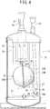
- Fig. 4 illustrates the state where the float of the oil separator of Fig. 2 moves up.
- Fig. 5 illustrates another embodiment of a float of an oil separator of the present invention.
- Fig. 6 illustrates still another embodiment of a float of an oil separator of the present invention.
- Fig. 7 illustrates a further embodiment of a float of an oil separator of the present invention.
- Fig. 8 illustrates a still further embodiment of a float of an oil separator of the present invention.
- a refrigerant circuit illustrated in Fig. 1 is to cool the chamber (not illustrated) of a deep freezer 1 that is an embodiment of a refrigerating cycle apparatus of the present invention to ultracold temperatures from -80°C to - 150°C, and the refrigerant circuit includes a high-temperature side refrigerant circuit 2 and a low-temperature side refrigerant circuit 3 cascaded to the high-temperature side refrigerant circuit 2.
- the high-temperature side refrigerant circuit 2 includes: a compressor 4; a condenser 6 as a radiator; a capillary tube (or an expansion valve) 7 as a pressure reducing unit and an evaporator 8 that are connected sequentially in a loop via pipes.
- the low-temperature side refrigerant circuit 3 includes: a compressor 9; an oil separator 11 according to the present invention; a condenser 12 as a radiator; a capillary tube (or an expansion valve) 13 as a pressure reducing unit and an evaporator 14 that are connected sequentially in a loop via pipes.
- the condenser 12 of this low-temperature side refrigerant circuit 3 and the evaporator 8 of the high-temperature side refrigerant circuit 2 are arranged in a heat-exchange relationship, thus configuring a cascade heat exchanger 16.
- the oil separator 11 plays a role to separate oil in a refrigerant discharged from the compressor 9 of the low-temperature side refrigerant circuit 3 and return the oil to the compressor 9, where a discharge pipe 9D of the compressor 9 of the low-temperature side refrigerant circuit 3 is connected to a refrigerant inlet pipe 17 of the oil separator 11 and a refrigerant outlet pipe 18 of the oil separator 11 is connected to the condenser 12.
- An oil returning pipe 19 of the oil separator 11 is connected to a suction pipe 9S of the compressor 9.
- gas refrigerant at a high temperature and a high pressure discharged from the compressor 4 flows into the condenser 6, and dissipates heat there to condense into liquid.
- the refrigerant subjected to condensation at the condenser 6 then is squeezed by the capillary tube 7 and then flows into the evaporator 8 for evaporation.
- the refrigerant exerts an endothermic effect.
- the refrigerant evaporated at the evaporator 8 is sucked into the compressor 4 again for repeated circulation.
- gas refrigerant at a high temperature and a high pressure discharged from the discharge pipe 9D of the compressor 9 flows into the oil separator 11 through the refrigerant inlet pipe 17.
- Refrigerant gas from which oil has been separated by this oil separator 11 flows out from the refrigerant outlet pipe 18, and flows into the condenser 12.
- the oil separated by the oil separator 11 is returned to the suction pipe 9S of the compressor 9 via the oil returning pipe 19 as described later.
- the low-temperature side refrigerant circuit 3 contains a refrigerant with an extremely low boiling point therein.
- the refrigerant can condense into liquid smoothly because the condenser 12 is cooled by the endothermic effect by the evaporator 8 of the high-temperature side refrigerant circuit 2 at the cascade heat exchanger 16.
- the refrigerant subjected to condensation at the condenser 12 then is squeezed by the capillary tube 13 and then flows into the evaporator 14 for evaporation.
- the refrigerant exerts an endothermic effect to cool the chamber not illustrated.
- the compressor 9 is turned ON and OFF in accordance with temperatures in the chamber, so that the chamber is cooled to set temperatures in the ultracold temperature range from -80°C to -150°C as described above.
- the refrigerant evaporated at the evaporator 14 is sucked into the compressor 9 again through the suction pipe 9S for repeated circulation. At this time, the oil flowing back through the oil returning pipe 19 as well as the refrigerant from the evaporator 14 are returned to the compressor 9 via the suction pipe 9S.
- reference numeral 21 denotes a tank with a predetermined capacity having a vertically long cylindrical shape.
- the tank 21 is hermetically sealed above and below so as to withstand high pressures.
- the refrigerant inlet pipe 17 and the refrigerant outlet pipe 18 are inserted into this tank 21 from the above and open at an upper part in the tank 21.
- the oil returning pipe 19 also is inserted into the tank 21 from the above and opens at a bottom part in the tank 21.
- a filter 22 Around the opening of the refrigerant inlet pipe 17 in the tank 21 is attached a filter 22, and the filter 22 separates oil in the refrigerant gas flowing from the refrigerant inlet pipe 17 as stated above.
- the separated oil drops from the filter 22 and is stored in the bottom part of the tank 21.
- the refrigerant gas from which oil has been separated by the filter 22 flows into the refrigerant outlet pipe 18 via the interior of the tank 21, and flows out to the condenser 12 from the oil separator 11.
- the refrigerant inlet pipe 17 and the refrigerant outlet pipe 18 in the tank 21 are separated by a partition 23 to prevent a so-called short circuit of the refrigerant gas.
- a float 24 having a hollow therein. This float 24 floats at the oil level of the oil separated by the filter 22 and stored in the bottom part to play a role of detecting the oil level.
- the float 24 is held vertically movably to the oil returning pipe 19 via a float lever 26 and a mounting hardware 27.
- the mounting hardware 27 is attached at a lower end portion of the oil returning pipe 19, and one end portion of the float lever 26 is vertically rotatably and pivotably supported by this mounting hardware 27 around a revolution shaft 28 in the horizontal direction. Then, the other end of the float lever 26 is welded for fixing to a side face of the float 24, thus allowing the float 24 to be held vertically movably in the tank 21 below the filter 22 or the like.
- the one end of the float lever 26 further extends from the revolution shaft 28 in the direction opposite to the float 24, and to this extension 26A is rotatably attached a lower end of a needle valve 29 (valve unit). The upper end of this needle valve 29 corresponds to the position of the lower end opening of the oil returning pipe 19.
- Reference numeral 31 denotes a holder to hold the positions of the oil returning pipe 19 and the float 24 in the tank 21.
- All of the floats 24 in the following embodiments are spheres having a hollow therein, including two separated hemispherical (having a hollow inside) first and second float members 24A and 24B made of stainless steel with flanges, which are mutually welded at the flanges F around the openings for fixing.
- first and second float members 24A and 24B made of stainless steel with flanges, which are mutually welded at the flanges F around the openings for fixing.
- the second float member 24B that is the uppermost part of the float 24 in the state where the float 24 descends has a hole bored therein, through which an equalizer tube 32 made of a thin copper pipe making up equalizer means of the present invention is inserted.
- a lower end 32A (one end) of this equalizer tube 32 opens at a bottom part in the float 24.
- an upper end 32B (the other end) of the equalizer tube 32 sticks out from the float 24 and then is bent downward, and opens downward above the oil level of the oil in the tank 21.
- a gap between the equalizer tube 32 and the hole of the second float member 24B is sealed by welding.
- the pressure in the tank 21 increases up to about 3 MPa in this embodiment.
- the pressure in the tank 21 decreases to about 0.5 MPa.
- the float members 24A and 24B configuring the float 24 and the welding portion of the flanges F are required to have a strength to withstand such a high pressure and to avoid metal fatigue due to such a pressure difference. This is because, if the float 24 breaks and oil enters into the float 24, the float will lose the buoyancy, which means that the needle valve 29 is kept close and oil cannot be returned to the compressor 9.
- the equalizer tube 32 allows the interior of the float 24 and the space above the oil level of the oil in the tank 21 to communicate with each other, thus eliminating the pressure difference between the interior and the exterior of the float 24 (pressure is equalized).
- the float 24 does not break without such a pressure-withstanding strength and welding quality.
- the float in the present embodiment is made of stainless steel, the float 24 may be shaped with other metals or materials other than metal such as hard synthetic resin. Therefore, burning of the compressor 9 or cooling error of the deep freezer 1 can be effectively prevented while remarkably reducing the manufacturing cost.
- the attachment of the equalizer tube 32 increases the weight of the float 24 itself, and therefore a material and dimensions of the equalizer tube 32 have to be decided with consideration given to margin of the buoyancy of the float 24.
- This margin of the buoyancy is decided by balance among the maximum buoyancy of the float 24 itself, the buoyancy of the float 24 around the revolution shaft 28 of the float lever 26 and moment of an application force of the needle valve 29, and therefore the material and the dimensions of the equalizer tube 32 are set so that the buoyancy can be within such margin even after the attachment of the equalizer tube 32.
- the float 24 is made of stainless steel, and has the volume of 137.3 (cc), the weight of 71.4 (g), the surface area of 128.7 (cm 2 ) and the maximum buoyancy of about 52.1 (g). Then, the margin of the buoyancy on the basis of the balance with the float lever 26 is about 17.9 (g). Then, when the equalizer tube 32 is made of a copper pipe as in the embodiment, the weight thereof is about 2.0 to 5.3 (g) even when the outer diameter is 2.4 to 4.76 (mm), the inner diameter is 1.2 to 3.46 (mm), the material thickness is 0.4 to 0.65 (mm) and the length is 70 (mm). Accordingly, enough buoyancy can be obtained. The same should apply to the case of using a stainless steel pipe or an iron pipe having a smaller specific gravity than a copper pipe.
- the equalizer tube 32 has to be filled with oil when the oil enters into the equalizer tube 32 from the lower end 32A.
- this sucking-up action is influenced by the viscosity of oil, when the inner diameter of the equalizer tube 32 is too large, oil cannot be sucked up from the float 24 when the pressure in the tank 21 decreases.
- the equalizer tube 32 when the equalizer tube 32 is too thin, the equalizer tube 32 may be collapsed during welding to the float member 24B. Therefore, the outer diameter and the inner diameter of the equalizer tube 32 have to be selected with consideration given to these matters.
- a copper pipe having the outer diameter of 3 (mm), the inner diameter of 2.2 (mm) and the material thickness of 0.4 (mm) was used, and it was confirmed by an experiment that the equalizer tube 32 had sufficient sucking-up ability when the pressure in the tank 21 decreases.
- Fig. 5 is a cross-sectional view of a float 24 in another embodiment of the present invention.
- an equalizer tube 32 includes a straight pipe, and an upper end 32B thereof is directed upward in the tank 21. Even such an equalizer tube 32 can eliminate a pressure difference between the interior and the exterior of the float 24. However, the upper end 32B directed downward as in the aforementioned embodiment can effectively prevent or suppress the problem that oil separated from a refrigerant flowing into the tank 21 and dropping from the filter 22 located above enters from the other end 32B of the equalizer tube 32.
- Fig. 6 is a cross-sectional view of a float 24 in still another embodiment of the present invention.
- the other end 32B of the equalizer tube 32 opens to be directed obliquely upward.
- Such a configuration allows oil dropping from the above to tend to flow downward along the outer face of the equalizer tube 32 obliquely descending from the other end 32B, thus suppressing the oil from flowing into the equalizer tube 32 from the opening of the other end 32B, and therefore entering of the oil to the equalizer tube 32 can be effectively prevented or suppressed.
- Fig. 7 is a cross-sectional view of a float 24 in a further embodiment of the present invention.
- the equalizer tube 32 has a curved shape along the outer face of the float 24 and is welded for fixing to the outer face. Then, a lower end 32A thereof is inserted through a hole formed at a lower end portion of the float 24 and opens at a bottom part of the float 24. Then, similarly to the aforementioned embodiment, an upper end 32B opens downward above the float 24.
- the equalizer tube 32 provided along the outer face of the float 24 in this way can eliminate the necessity to insert the equalizer tube 32 in the float 24 as in Fig. 2 , Fig. 5 and Fig. 6 , and therefore productivity can be more improved.
- Fig. 8 is a cross-sectional view of a float 24 in a still further embodiment of the present invention.
- first and second float members 24A and 24B configuring the float 24 include grooves formed at flanges F thereof beforehand so as to be opposed mutually, and in these grooves an equalizing path (equalizing means) 33 is formed.
- a lower end 33A of the equalizing path 33 opens to the interior of the float 24 at a bottom portion of the float 24, and an upper end 33B of the equalizing path 33 opens externally at an upper portion of the float 24.
- this equalizing path 33 When forming this equalizing path 33, the flanges F at a portion other than the part corresponding to the equalizing path are mutually bonded firstly, and pressure is applied thereto to let a not-bonded portion swell. Thereby the aforementioned opposed grooves are formed at the flanges F of both of the float members 24A and 24B, and the interior therebetween becomes the equalizing path 33.
- the thus formed equalizing path 33 in the flanges F can eliminate the necessity of attaching a pipe, thus reducing the number of components and leading to the improvement of productivity.
- the present invention has been described by way of the oil separator 11 that mechanically controls the returning of oil by the vertical movement of the float 24 using the float lever 26 and the needle valve 29.
- the present invention is not limited to such an example, and is also effective to an oil separator as in the aforementioned Patent Document 1 where the vertical movement of a float 24 opens and closes a contact and so opens and closes an electromagnetic valve (valve unit) provided at an oil returning pipe 19.
Landscapes
- Engineering & Computer Science (AREA)
- Chemical & Material Sciences (AREA)
- Analytical Chemistry (AREA)
- Power Engineering (AREA)
- Physics & Mathematics (AREA)
- Mechanical Engineering (AREA)
- Thermal Sciences (AREA)
- General Engineering & Computer Science (AREA)
- Compressor (AREA)
Abstract
Description
- The present invention relates to oil separators to return oil in a refrigerant that is discharged from a compressor in a refrigerating cycle apparatus such as a deep freezer and relates to refrigerating cycle apparatuses using the same.
- Conventionally deep freezers used for laboratories or the like are provided with a refrigerating cycle including a refrigerant circuit where a compressor, a condenser (radiator), a pressure reducing unit, an evaporator and the like are connected sequentially in a loop. This refrigerating cycle is filled with a refrigerant as well as a predetermined amount of oil to lubricate a sliding portion of the compressor. A part of this oil is discharged to the refrigerating cycle from the compressor together with the refrigerant.
- The oil discharged to the refrigerant cycle hinders circulation of the refrigerant at the pressure reducing unit and the evaporator, and causes problems such as burning due to depletion of the oil in the compressor. To cope with the problem, an oil separator conventionally is provided between the compressor and the condenser.
- This oil separator includes a tank with a predetermined capacity, into which a refrigerant (including oil) discharged from the compressor flows. Then, the oil in the refrigerant is separated in the tank with means such as a filter or a centrifugal separator, and the refrigerant only is made to flow out from the tank to the condenser. The oil is stored in the tank. A float provided in the tank floats at the oil level and is vertically movably held in the tank.
- Accordingly, this float moves up and down with the oil level in the tank. Then, when the amount of the oil in the tank increases until the float rises up to a predetermined position with the oil level, a valve unit opens to let the oil in the tank return to the intake side of the compressor. Thereby, the oil discharged to the refrigerating cycle is returned, thus coping with the aforementioned problem (see Japanese Patent Application Laid-Open No.
H9-72635 - Meanwhile, the refrigerant discharged from the compressor is at an extremely high pressure such as 3 MPa during the operation of the compressor. On the other hand, when the compressor stops, the pressure decreases to about 0.5 MPa. Accordingly the pressure in the oil separator also frequently changes between such a high pressure and a low pressure. Therefore the float is required to have strength to withstand such a large pressure change. The float is typically configured by welding two separated hemispheres (having a hollow inside) made of metal such as iron or stainless steel at their flanges, and the welding of high quality is required as well, thus increasing the manufacturing cost.
- Additionally, due to metal fatigue inevitably generated in the float because of the pressure change with time, the float may lose the buoyancy by oil entering into the float through a broken portion. In that case, the float cannot detect up/down movement of the oil level and so the oil-returning function is unfortunately disabled.
- In order to cope with such conventional technical problems, it is an object of the present invention to provide an oil separator capable of preventing the breakage of a float with an extremely simple configuration and a refrigerating cycle apparatus using the same.
- An oil separator according to a first aspect of the present application is to separate oil in a refrigerant that is discharged from a compressor and return the oil to the compressor. The oil separator includes: a tank, into which a refrigerant discharged from the compressor flows; a float having a hollow therein that is held vertically movably in the tank, the float moving up and down with a change of an oil level in the tank; and a valve unit to return oil in the tank to the compressor in accordance with up/down movement of the float. The float includes equalizing means having one end that opens at a bottom part in the float and the other end that opens outside of the float and above the oil level in the tank.
- According to a second aspect of the present application, the other end of the equalizing means in the oil separator of the aforementioned first aspect of the present application opens downward.
- According to a third aspect of the present application, the other end of the equalizing means in the oil separator of the aforementioned first aspect of the present application opens obliquely upward.
- According to a fourth aspect of the present application, the equalizing means in the oil separator of the aforementioned aspects of the present application is disposed along an outer face of the float.
- According to a fifth aspect of the present application, the float in the oil separator of the aforementioned first to third aspects of the present application includes first and second float members each having a flange at an end face, the float members being welded at the flanges, and the equalizing means includes an equalizing path provided in the flanges.
- A refrigerating cycle apparatus according to a sixth aspect of the present application includes a refrigerant circuit including a compressor, a radiator, a pressure reducing unit and an evaporator that are connected in a loop. Between the compressor and the radiator is connected the oil separator according to any one of the aforementioned first to fifth aspects of the present application.
- According to the first aspect of the present application, the oil separator is to separate oil in a refrigerant that is discharged from a compressor and return the oil to the compressor, and the oil separator includes: a tank, into which a refrigerant discharged from the compressor flows; a float having a hollow therein that is held vertically movably in the tank, the float moving up and down with a change of an oil level in the tank; and a valve unit to return oil in the tank to the compressor in accordance with up/down movement of the float. The float includes equalizing means having one end that opens at a bottom part in the float and the other end that opens outside of the float and above the oil level in the tank. With this configuration, the space above the oil level in the tank and the interior of the float can communicate with each other by the equalizing means.
- This configuration eliminates a pressure difference between the interior and the exterior of the float. Therefore a problem of breakage of a float due to a high pressure in the tank and a pressure change can be solved with a simple configuration even for a float with a low strength. Accordingly, burning of a compressor or cooling error of a refrigerating cycle apparatus as in the aforementioned sixth aspect of the present application can be effectively prevented while remarkably reducing the manufacturing cost. In case where oil enters into the float from the other end of the equalizing means, the oil flows out from the tank through the equalizing means when the pressure in the tank decreases, and so this configuration is free from the problem about buoyancy.
- In this case, the other end of the equalizing means opening downward as in the second aspect of the present application can effectively prevent or suppress the problem that oil separated from a refrigerant flowing into the tank and typically dropping from the filter located above enters from the other end of the equalizing means.
- The other end of the equalizing means opening obliquely upward as in the third aspect of the present application allows oil dropping from the above to tend to flow downward along the outer face of the equalizing means. Therefore this configuration also can effectively prevent or suppress entering of oil from the other end to the equalizing means.
- The equalizing means disposed along an outer face of the float as in the fourth aspect of the present application can eliminate the necessity of providing equalizing means in the float, thus improving productivity more.
- As in the fifth aspect of the present application, the float includes first and second float members each having a flange at an end face, the float members being welded at the flanges, and the equalizing means includes an equalizing path provided in the flanges. This configuration can realize equalizing means without using a pipe or the like, thus reducing the number of components and leading to the improvement of productivity.
-
Fig. 1 is a refrigerant circuit diagram of a deep freezer that is an embodiment of a refrigerating cycle apparatus to which the present invention is applied. -
Fig. 2 is a vertical sectional view of an oil separator of the present invention. -
Fig. 3 is another vertical sectional view of an oil separator of the present invention. -
Fig. 4 illustrates the state where the float of the oil separator ofFig. 2 moves up. -
Fig. 5 illustrates another embodiment of a float of an oil separator of the present invention. -
Fig. 6 illustrates still another embodiment of a float of an oil separator of the present invention. -
Fig. 7 illustrates a further embodiment of a float of an oil separator of the present invention. -
Fig. 8 illustrates a still further embodiment of a float of an oil separator of the present invention. - The following describes embodiments of the present invention in detail, with reference to the drawings. A refrigerant circuit illustrated in
Fig. 1 is to cool the chamber (not illustrated) of adeep freezer 1 that is an embodiment of a refrigerating cycle apparatus of the present invention to ultracold temperatures from -80°C to - 150°C, and the refrigerant circuit includes a high-temperatureside refrigerant circuit 2 and a low-temperatureside refrigerant circuit 3 cascaded to the high-temperatureside refrigerant circuit 2. - The high-temperature
side refrigerant circuit 2 includes: acompressor 4; acondenser 6 as a radiator; a capillary tube (or an expansion valve) 7 as a pressure reducing unit and anevaporator 8 that are connected sequentially in a loop via pipes. The low-temperatureside refrigerant circuit 3 includes: acompressor 9; anoil separator 11 according to the present invention; acondenser 12 as a radiator; a capillary tube (or an expansion valve) 13 as a pressure reducing unit and anevaporator 14 that are connected sequentially in a loop via pipes. Thecondenser 12 of this low-temperatureside refrigerant circuit 3 and theevaporator 8 of the high-temperatureside refrigerant circuit 2 are arranged in a heat-exchange relationship, thus configuring acascade heat exchanger 16. - The detailed configuration of the
oil separator 11 is described later. Theoil separator 11 plays a role to separate oil in a refrigerant discharged from thecompressor 9 of the low-temperatureside refrigerant circuit 3 and return the oil to thecompressor 9, where adischarge pipe 9D of thecompressor 9 of the low-temperatureside refrigerant circuit 3 is connected to arefrigerant inlet pipe 17 of theoil separator 11 and arefrigerant outlet pipe 18 of theoil separator 11 is connected to thecondenser 12. Anoil returning pipe 19 of theoil separator 11 is connected to asuction pipe 9S of thecompressor 9. - Then, when the
compressor 4 of the high-temperature siderefrigerant circuit 2 is operated, gas refrigerant at a high temperature and a high pressure discharged from thecompressor 4 flows into thecondenser 6, and dissipates heat there to condense into liquid. The refrigerant subjected to condensation at thecondenser 6 then is squeezed by the capillary tube 7 and then flows into theevaporator 8 for evaporation. At this time, the refrigerant exerts an endothermic effect. The refrigerant evaporated at theevaporator 8 is sucked into thecompressor 4 again for repeated circulation. - When the
compressor 9 of the low-temperature siderefrigerant circuit 3 is operated, gas refrigerant at a high temperature and a high pressure discharged from thedischarge pipe 9D of thecompressor 9 flows into theoil separator 11 through therefrigerant inlet pipe 17. Refrigerant gas from which oil has been separated by thisoil separator 11 flows out from therefrigerant outlet pipe 18, and flows into thecondenser 12. Herein, the oil separated by theoil separator 11 is returned to thesuction pipe 9S of thecompressor 9 via theoil returning pipe 19 as described later. - In order to achieve the aforementioned ultracold temperatures, the low-temperature side
refrigerant circuit 3 contains a refrigerant with an extremely low boiling point therein. The refrigerant, however, can condense into liquid smoothly because thecondenser 12 is cooled by the endothermic effect by theevaporator 8 of the high-temperature siderefrigerant circuit 2 at thecascade heat exchanger 16. The refrigerant subjected to condensation at thecondenser 12 then is squeezed by thecapillary tube 13 and then flows into theevaporator 14 for evaporation. At this time, the refrigerant exerts an endothermic effect to cool the chamber not illustrated. Then thecompressor 9 is turned ON and OFF in accordance with temperatures in the chamber, so that the chamber is cooled to set temperatures in the ultracold temperature range from -80°C to -150°C as described above. - The refrigerant evaporated at the
evaporator 14 is sucked into thecompressor 9 again through thesuction pipe 9S for repeated circulation. At this time, the oil flowing back through theoil returning pipe 19 as well as the refrigerant from theevaporator 14 are returned to thecompressor 9 via thesuction pipe 9S. - The following describes one embodiment of the
oil separator 11 of the present invention, with reference toFig. 2 to Fig. 4 . In these drawings,reference numeral 21 denotes a tank with a predetermined capacity having a vertically long cylindrical shape. Thetank 21 is hermetically sealed above and below so as to withstand high pressures. Therefrigerant inlet pipe 17 and therefrigerant outlet pipe 18 are inserted into thistank 21 from the above and open at an upper part in thetank 21. Theoil returning pipe 19 also is inserted into thetank 21 from the above and opens at a bottom part in thetank 21. - Around the opening of the
refrigerant inlet pipe 17 in thetank 21 is attached afilter 22, and thefilter 22 separates oil in the refrigerant gas flowing from therefrigerant inlet pipe 17 as stated above. The separated oil drops from thefilter 22 and is stored in the bottom part of thetank 21. The refrigerant gas from which oil has been separated by thefilter 22 flows into therefrigerant outlet pipe 18 via the interior of thetank 21, and flows out to thecondenser 12 from theoil separator 11. This prevents the oil from flowing out to a downstream of theoil separator 11 of the low-temperature siderefrigerant circuit 3, and can avoid problems such as a failure in refrigerant circulation due to solidification of the oil at a portion at ultracold temperatures such as at theevaporator 14 as state above. Therefrigerant inlet pipe 17 and therefrigerant outlet pipe 18 in thetank 21 are separated by apartition 23 to prevent a so-called short circuit of the refrigerant gas. - At the lower part of the
tank 21 is housed afloat 24 having a hollow therein. Thisfloat 24 floats at the oil level of the oil separated by thefilter 22 and stored in the bottom part to play a role of detecting the oil level. Thefloat 24 is held vertically movably to theoil returning pipe 19 via afloat lever 26 and a mountinghardware 27. - That is, the mounting
hardware 27 is attached at a lower end portion of theoil returning pipe 19, and one end portion of thefloat lever 26 is vertically rotatably and pivotably supported by this mountinghardware 27 around arevolution shaft 28 in the horizontal direction. Then, the other end of thefloat lever 26 is welded for fixing to a side face of thefloat 24, thus allowing thefloat 24 to be held vertically movably in thetank 21 below thefilter 22 or the like. The one end of thefloat lever 26 further extends from therevolution shaft 28 in the direction opposite to thefloat 24, and to thisextension 26A is rotatably attached a lower end of a needle valve 29 (valve unit). The upper end of thisneedle valve 29 corresponds to the position of the lower end opening of theoil returning pipe 19. When theneedle valve 29 moves up, the upper end thereof blocks the lower end opening of theoil returning pipe 19 and when theneedle valve 29 moves down, it opens the lower end opening.Reference numeral 31 denotes a holder to hold the positions of theoil returning pipe 19 and thefloat 24 in thetank 21. - As described above, oil separated from the refrigerant gas by the
filter 22 drops from thefilter 22 and is stored in the bottom part of thetank 21. Thefloat 24 floats at the oil level of the stored oil. When the amount of the oil increases, the oil level rises and accordingly thefloat 24 also rises. Therefore, thefloat lever 26 rotates clockwise inFig. 2 around therevolution shaft 28 and assumes the state ofFig. 4 . This rotation rotates theextension 26A as well clockwise, and therefore theneedle valve 29 is pulled up, thus letting the lower end opening of theoil returning pipe 19 open (Fig. 4 ). As a result, since the interior of thetank 21 is at a high pressure during the operation of thecompressor 9, the oil stored in thetank 21 flows into the lower end opening of theoil returning pipe 19 and is returned to thecompressor 9 via theoil returning pipe 19 as stated above. This can prevent burning of thecompressor 9 due to depletion of the oil. - When the oil flows out, the amount of the oil in the
tank 21 decreases and accordingly the oil level drops. Then, thefloat 24 also descends, and therefore thefloat lever 26 rotates counterclockwise inFig. 2 around therevolution shaft 28. This rotation rotates theextension 26A as well counterclockwise, and therefore theneedle valve 29 is pushed upward, thus blocking the lower end opening of the oil returning pipe 19 (Figs. 2 and3 ). This can adjust the oil amount in thetank 21 of theoil separator 11 always not to exceed a predetermined value. - The following describes the configuration of the
float 24 in theoil separator 11 of the present invention. All of thefloats 24 in the following embodiments are spheres having a hollow therein, including two separated hemispherical (having a hollow inside) first andsecond float members Fig. 2 andFig. 3 , thesecond float member 24B that is the uppermost part of thefloat 24 in the state where thefloat 24 descends has a hole bored therein, through which anequalizer tube 32 made of a thin copper pipe making up equalizer means of the present invention is inserted. - A
lower end 32A (one end) of thisequalizer tube 32 opens at a bottom part in thefloat 24. In this embodiment, anupper end 32B (the other end) of theequalizer tube 32 sticks out from thefloat 24 and then is bent downward, and opens downward above the oil level of the oil in thetank 21. Herein, a gap between theequalizer tube 32 and the hole of thesecond float member 24B is sealed by welding. - As described above, during the operation of the
compressor 9, since gas refrigerant at a high temperature and a high pressure is discharged from thecompressor 9 and flows into theoil separator 11, the pressure in thetank 21 increases up to about 3 MPa in this embodiment. When thecompressor 9 stops, the pressure in thetank 21 decreases to about 0.5 MPa. Conventionally thefloat members float 24 and the welding portion of the flanges F are required to have a strength to withstand such a high pressure and to avoid metal fatigue due to such a pressure difference. This is because, if thefloat 24 breaks and oil enters into thefloat 24, the float will lose the buoyancy, which means that theneedle valve 29 is kept close and oil cannot be returned to thecompressor 9. - According to the present invention, however, the
equalizer tube 32 allows the interior of thefloat 24 and the space above the oil level of the oil in thetank 21 to communicate with each other, thus eliminating the pressure difference between the interior and the exterior of the float 24 (pressure is equalized). As a result, thefloat 24 does not break without such a pressure-withstanding strength and welding quality. Accordingly, although the float in the present embodiment is made of stainless steel, thefloat 24 may be shaped with other metals or materials other than metal such as hard synthetic resin. Therefore, burning of thecompressor 9 or cooling error of thedeep freezer 1 can be effectively prevented while remarkably reducing the manufacturing cost. - Note here that the attachment of the
equalizer tube 32 increases the weight of thefloat 24 itself, and therefore a material and dimensions of theequalizer tube 32 have to be decided with consideration given to margin of the buoyancy of thefloat 24. This margin of the buoyancy is decided by balance among the maximum buoyancy of thefloat 24 itself, the buoyancy of thefloat 24 around therevolution shaft 28 of thefloat lever 26 and moment of an application force of theneedle valve 29, and therefore the material and the dimensions of theequalizer tube 32 are set so that the buoyancy can be within such margin even after the attachment of theequalizer tube 32. - In this embodiment, the
float 24 is made of stainless steel, and has the volume of 137.3 (cc), the weight of 71.4 (g), the surface area of 128.7 (cm2) and the maximum buoyancy of about 52.1 (g). Then, the margin of the buoyancy on the basis of the balance with thefloat lever 26 is about 17.9 (g). Then, when theequalizer tube 32 is made of a copper pipe as in the embodiment, the weight thereof is about 2.0 to 5.3 (g) even when the outer diameter is 2.4 to 4.76 (mm), the inner diameter is 1.2 to 3.46 (mm), the material thickness is 0.4 to 0.65 (mm) and the length is 70 (mm). Accordingly, enough buoyancy can be obtained. The same should apply to the case of using a stainless steel pipe or an iron pipe having a smaller specific gravity than a copper pipe. - Further, since the
other end 32B of theequalizer tube 32 opens downward in this embodiment, oil dropping from thefilter 22 located above hardly enters into thefloat 24 from theother end 32B of theequalizer tube 32. In case where oil enters into thefloat 24 from theother end 32B of theequalizer tube 32, when thecompressor 9 stops and the pressure in thetank 21 decreases, oil at the bottom part in thefloat 24 flows from thelower end 32A of theequalizer tube 32 to theequalizer tube 32 and passes therethrough to flow out from theupper end 32B to thetank 21 as stated above. Therefore, this configuration is free from the problem of buoyancy due to the flowing oil. - However, in order to suck up oil in the
float 24 with theequalizer tube 32 when the pressure in thetank 21 decreases, theequalizer tube 32 has to be filled with oil when the oil enters into theequalizer tube 32 from thelower end 32A. Although this sucking-up action is influenced by the viscosity of oil, when the inner diameter of theequalizer tube 32 is too large, oil cannot be sucked up from thefloat 24 when the pressure in thetank 21 decreases. - Conversely when the
equalizer tube 32 is too thin, theequalizer tube 32 may be collapsed during welding to thefloat member 24B. Therefore, the outer diameter and the inner diameter of theequalizer tube 32 have to be selected with consideration given to these matters. In the embodiments, a copper pipe having the outer diameter of 3 (mm), the inner diameter of 2.2 (mm) and the material thickness of 0.4 (mm) was used, and it was confirmed by an experiment that theequalizer tube 32 had sufficient sucking-up ability when the pressure in thetank 21 decreases. -
Fig. 5 is a cross-sectional view of afloat 24 in another embodiment of the present invention. In this case, anequalizer tube 32 includes a straight pipe, and anupper end 32B thereof is directed upward in thetank 21. Even such anequalizer tube 32 can eliminate a pressure difference between the interior and the exterior of thefloat 24. However, theupper end 32B directed downward as in the aforementioned embodiment can effectively prevent or suppress the problem that oil separated from a refrigerant flowing into thetank 21 and dropping from thefilter 22 located above enters from theother end 32B of theequalizer tube 32. -
Fig. 6 is a cross-sectional view of afloat 24 in still another embodiment of the present invention. In this case, theother end 32B of theequalizer tube 32 opens to be directed obliquely upward. Such a configuration allows oil dropping from the above to tend to flow downward along the outer face of theequalizer tube 32 obliquely descending from theother end 32B, thus suppressing the oil from flowing into theequalizer tube 32 from the opening of theother end 32B, and therefore entering of the oil to theequalizer tube 32 can be effectively prevented or suppressed. -
Fig. 7 is a cross-sectional view of afloat 24 in a further embodiment of the present invention. In this case, theequalizer tube 32 has a curved shape along the outer face of thefloat 24 and is welded for fixing to the outer face. Then, alower end 32A thereof is inserted through a hole formed at a lower end portion of thefloat 24 and opens at a bottom part of thefloat 24. Then, similarly to the aforementioned embodiment, anupper end 32B opens downward above thefloat 24. - The
equalizer tube 32 provided along the outer face of thefloat 24 in this way can eliminate the necessity to insert theequalizer tube 32 in thefloat 24 as inFig. 2 ,Fig. 5 andFig. 6 , and therefore productivity can be more improved. -
Fig. 8 is a cross-sectional view of afloat 24 in a still further embodiment of the present invention. In this case, first andsecond float members float 24 include grooves formed at flanges F thereof beforehand so as to be opposed mutually, and in these grooves an equalizing path (equalizing means) 33 is formed. Alower end 33A of the equalizingpath 33 opens to the interior of thefloat 24 at a bottom portion of thefloat 24, and anupper end 33B of the equalizingpath 33 opens externally at an upper portion of thefloat 24. - When forming this equalizing
path 33, the flanges F at a portion other than the part corresponding to the equalizing path are mutually bonded firstly, and pressure is applied thereto to let a not-bonded portion swell. Thereby the aforementioned opposed grooves are formed at the flanges F of both of thefloat members path 33. The thus formed equalizingpath 33 in the flanges F can eliminate the necessity of attaching a pipe, thus reducing the number of components and leading to the improvement of productivity. - In these embodiments, the present invention has been described by way of the
oil separator 11 that mechanically controls the returning of oil by the vertical movement of thefloat 24 using thefloat lever 26 and theneedle valve 29. The present invention, however, is not limited to such an example, and is also effective to an oil separator as in theaforementioned Patent Document 1 where the vertical movement of afloat 24 opens and closes a contact and so opens and closes an electromagnetic valve (valve unit) provided at anoil returning pipe 19.
Claims (6)
- An oil separator to separate oil in a refrigerant that is discharged from a compressor and return the oil to the compressor, comprising:a tank, into which a refrigerant discharged from the compressor flows;a float having a hollow therein that is held vertically movably in the tank, the float moving up and down with a change of an oil level in the tank; anda valve unit to return oil in the tank to the compressor in accordance with up/down movement of the float,wherein the float includes equalizing means having one end that opens at a bottom part in the float and the other end that opens outside of the float and above the oil level in the tank.
- The oil separator according to claim 1, wherein the other end of the equalizing means opens downward.
- The oil separator according to claim 1, wherein the other end of the equalizing means opens obliquely upward.
- The oil separator according to any one of claims 1 to 3, wherein the equalizing means is disposed along an outer face of the float.
- The oil separator according to any one of claims 1 to 3, wherein the float includes first and second float members each having a flange at an end face, the float members being welded at the flanges, and the equalizing means includes an equalizing path provided in the flanges.
- A refrigerating cycle apparatus, comprising a refrigerant circuit including a compressor, a radiator, a pressure reducing unit and an evaporator that are connected in a loop, wherein between the compressor and the radiator is connected the oil separator according to any one of claims 1 to 5.
Applications Claiming Priority (1)
| Application Number | Priority Date | Filing Date | Title |
|---|---|---|---|
| JP2011057892A JP5753964B2 (en) | 2011-03-16 | 2011-03-16 | Oil separator and refrigeration cycle apparatus using the same |
Publications (2)
| Publication Number | Publication Date |
|---|---|
| EP2500677A1 true EP2500677A1 (en) | 2012-09-19 |
| EP2500677B1 EP2500677B1 (en) | 2014-11-05 |
Family
ID=45819010
Family Applications (1)
| Application Number | Title | Priority Date | Filing Date |
|---|---|---|---|
| EP20120157699 Active EP2500677B1 (en) | 2011-03-16 | 2012-03-01 | Oil separator and refrigerating cycle apparatus using the same |
Country Status (3)
| Country | Link |
|---|---|
| US (1) | US9068769B2 (en) |
| EP (1) | EP2500677B1 (en) |
| JP (1) | JP5753964B2 (en) |
Families Citing this family (7)
| Publication number | Priority date | Publication date | Assignee | Title |
|---|---|---|---|---|
| CN105393066B (en) * | 2013-05-03 | 2017-08-08 | 特灵空调系统(中国)有限公司 | Oil return control in HAVC system |
| US10309698B2 (en) | 2013-05-03 | 2019-06-04 | Trane International Inc. | Oil return management in a HVAC system |
| JP6143633B2 (en) | 2013-10-15 | 2017-06-07 | 住友重機械工業株式会社 | Compressor and compressor oil quantity management system |
| EP3015153B1 (en) | 2014-10-29 | 2020-10-28 | Mann + Hummel Gmbh | Separation element and pressure accumulator system |
| US10845106B2 (en) * | 2017-12-12 | 2020-11-24 | Rheem Manufacturing Company | Accumulator and oil separator |
| CN111765674A (en) * | 2019-03-30 | 2020-10-13 | 浙江三花智能控制股份有限公司 | Oil separator and refrigeration system having the same |
| CN113530797A (en) * | 2020-04-17 | 2021-10-22 | 广东美的白色家电技术创新中心有限公司 | Oil separators, compressor assemblies and heat exchange equipment |
Citations (4)
| Publication number | Priority date | Publication date | Assignee | Title |
|---|---|---|---|---|
| SU417667A1 (en) * | 1971-10-05 | 1974-02-28 | ||
| JPH0972635A (en) | 1995-09-04 | 1997-03-18 | Izumi Giken:Kk | Oil separator |
| EP1106229A1 (en) * | 1999-12-03 | 2001-06-13 | Frigomec S.r.l. | Oil separator |
| CN2893562Y (en) * | 2006-02-17 | 2007-04-25 | 洪灿淙 | compressor oil separator |
Family Cites Families (10)
| Publication number | Priority date | Publication date | Assignee | Title |
|---|---|---|---|---|
| US3850554A (en) * | 1973-04-05 | 1974-11-26 | Rudy S | Rotary compressors with injection of liquid |
| US5040382A (en) * | 1990-06-19 | 1991-08-20 | 501 Wynn's Climate Systems, Inc. | Refrigerant recovery system |
| US5095713A (en) * | 1991-01-22 | 1992-03-17 | Kent-Moore Corporation | Refrigerant handling system and method with multiple refrigerant capability |
| US5363662A (en) * | 1992-06-30 | 1994-11-15 | Todack James J | Refrigerant recovery and recycling method and apparatus |
| US5325675A (en) * | 1993-08-02 | 1994-07-05 | Spx Corporation | Refrigerant handling system and method with enhanced recovery vacuum capability |
| JP2000227356A (en) * | 1999-02-04 | 2000-08-15 | Saginomiya Seisakusho Inc | Level gauge float |
| US6244055B1 (en) * | 1999-06-01 | 2001-06-12 | Century Manufacturing Company | Refrigerant recovery and recycling system |
| US6314749B1 (en) * | 2000-02-03 | 2001-11-13 | Leon R. Van Steenburgh, Jr. | Self-clearing vacuum pump with external cooling for evacuating refrigerant storage devices and systems |
| JP2005054702A (en) * | 2003-08-06 | 2005-03-03 | Nissan Motor Co Ltd | Oil return passage structure for internal combustion engine |
| JP4699501B2 (en) * | 2008-09-10 | 2011-06-15 | 日立アプライアンス株式会社 | Positive displacement compressor |
-
2011
- 2011-03-16 JP JP2011057892A patent/JP5753964B2/en active Active
-
2012
- 2012-03-01 EP EP20120157699 patent/EP2500677B1/en active Active
- 2012-03-09 US US13/416,655 patent/US9068769B2/en active Active
Patent Citations (4)
| Publication number | Priority date | Publication date | Assignee | Title |
|---|---|---|---|---|
| SU417667A1 (en) * | 1971-10-05 | 1974-02-28 | ||
| JPH0972635A (en) | 1995-09-04 | 1997-03-18 | Izumi Giken:Kk | Oil separator |
| EP1106229A1 (en) * | 1999-12-03 | 2001-06-13 | Frigomec S.r.l. | Oil separator |
| CN2893562Y (en) * | 2006-02-17 | 2007-04-25 | 洪灿淙 | compressor oil separator |
Also Published As
| Publication number | Publication date |
|---|---|
| US20120234037A1 (en) | 2012-09-20 |
| JP2012193893A (en) | 2012-10-11 |
| US9068769B2 (en) | 2015-06-30 |
| EP2500677B1 (en) | 2014-11-05 |
| JP5753964B2 (en) | 2015-07-22 |
Similar Documents
| Publication | Publication Date | Title |
|---|---|---|
| EP2500677B1 (en) | Oil separator and refrigerating cycle apparatus using the same | |
| US8783059B2 (en) | Refrigerating air-conditioning apparatus | |
| JP3339302B2 (en) | accumulator | |
| JP2004526934A (en) | Internal heat exchanger accumulator | |
| CN110573809B (en) | Oil separator and refrigeration cycle device | |
| JP5978046B2 (en) | Oil separator and refrigeration cycle apparatus | |
| JPWO2010137274A1 (en) | Refrigeration cycle equipment | |
| WO2013076971A1 (en) | Gas-liquid separator and refrigeration cycle device | |
| KR100817027B1 (en) | Apparatus and method for evacuating vapors and liquids | |
| JP6829664B2 (en) | Compressed refrigerator | |
| JP4742985B2 (en) | Expander-integrated compressor and refrigeration cycle apparatus | |
| KR102201746B1 (en) | Economizer comprising condenser and turbo chiller comprising the same | |
| CN114508878B (en) | Separator and refrigeration unit fluid conditioning device | |
| JP2014062463A (en) | Oil separator, compressor including the same, and refrigeration cycle device including the same | |
| JPH07332810A (en) | Oil mist separator for refrigeration equipment | |
| JP2000088369A (en) | Refrigeration cycle | |
| JP6655327B2 (en) | Hermetic scroll compressor and refrigeration air conditioner | |
| WO2018135013A1 (en) | Compressor and refrigeration cycle system | |
| JP2006275413A (en) | Refrigerating circuit | |
| JP2008304097A (en) | Accumulator | |
| JP5981860B2 (en) | Air conditioner | |
| KR20150072168A (en) | Variable expansion device, economizer and turbo chiller comprising the same | |
| US20250116442A1 (en) | Condenser vessel, system, and method for separating oil from an oil-refrigerant mixture | |
| CN120368491A (en) | Oil return device for evaporator, air conditioning system and control method of air conditioning system | |
| WO2020157806A1 (en) | Refrigerator |
Legal Events
| Date | Code | Title | Description |
|---|---|---|---|
| PUAI | Public reference made under article 153(3) epc to a published international application that has entered the european phase |
Free format text: ORIGINAL CODE: 0009012 |
|
| AK | Designated contracting states |
Kind code of ref document: A1 Designated state(s): AL AT BE BG CH CY CZ DE DK EE ES FI FR GB GR HR HU IE IS IT LI LT LU LV MC MK MT NL NO PL PT RO RS SE SI SK SM TR |
|
| AX | Request for extension of the european patent |
Extension state: BA ME |
|
| 17P | Request for examination filed |
Effective date: 20130315 |
|
| GRAP | Despatch of communication of intention to grant a patent |
Free format text: ORIGINAL CODE: EPIDOSNIGR1 |
|
| INTG | Intention to grant announced |
Effective date: 20140605 |
|
| GRAS | Grant fee paid |
Free format text: ORIGINAL CODE: EPIDOSNIGR3 |
|
| GRAA | (expected) grant |
Free format text: ORIGINAL CODE: 0009210 |
|
| AK | Designated contracting states |
Kind code of ref document: B1 Designated state(s): AL AT BE BG CH CY CZ DE DK EE ES FI FR GB GR HR HU IE IS IT LI LT LU LV MC MK MT NL NO PL PT RO RS SE SI SK SM TR |
|
| AX | Request for extension of the european patent |
Extension state: BA ME |
|
| REG | Reference to a national code |
Ref country code: GB Ref legal event code: FG4D |
|
| REG | Reference to a national code |
Ref country code: CH Ref legal event code: EP |
|
| REG | Reference to a national code |
Ref country code: AT Ref legal event code: REF Ref document number: 694845 Country of ref document: AT Kind code of ref document: T Effective date: 20141115 |
|
| REG | Reference to a national code |
Ref country code: IE Ref legal event code: FG4D |
|
| REG | Reference to a national code |
Ref country code: DE Ref legal event code: R096 Ref document number: 602012003621 Country of ref document: DE Effective date: 20141224 |
|
| REG | Reference to a national code |
Ref country code: NL Ref legal event code: T3 |
|
| REG | Reference to a national code |
Ref country code: AT Ref legal event code: MK05 Ref document number: 694845 Country of ref document: AT Kind code of ref document: T Effective date: 20141105 |
|
| RAP2 | Party data changed (patent owner data changed or rights of a patent transferred) |
Owner name: PANASONIC HEALTHCARE HOLDINGS CO., LTD. |
|
| REG | Reference to a national code |
Ref country code: LT Ref legal event code: MG4D |
|
| PG25 | Lapsed in a contracting state [announced via postgrant information from national office to epo] |
Ref country code: FI Free format text: LAPSE BECAUSE OF FAILURE TO SUBMIT A TRANSLATION OF THE DESCRIPTION OR TO PAY THE FEE WITHIN THE PRESCRIBED TIME-LIMIT Effective date: 20141105 Ref country code: LT Free format text: LAPSE BECAUSE OF FAILURE TO SUBMIT A TRANSLATION OF THE DESCRIPTION OR TO PAY THE FEE WITHIN THE PRESCRIBED TIME-LIMIT Effective date: 20141105 Ref country code: NO Free format text: LAPSE BECAUSE OF FAILURE TO SUBMIT A TRANSLATION OF THE DESCRIPTION OR TO PAY THE FEE WITHIN THE PRESCRIBED TIME-LIMIT Effective date: 20150205 Ref country code: IS Free format text: LAPSE BECAUSE OF FAILURE TO SUBMIT A TRANSLATION OF THE DESCRIPTION OR TO PAY THE FEE WITHIN THE PRESCRIBED TIME-LIMIT Effective date: 20150305 Ref country code: ES Free format text: LAPSE BECAUSE OF FAILURE TO SUBMIT A TRANSLATION OF THE DESCRIPTION OR TO PAY THE FEE WITHIN THE PRESCRIBED TIME-LIMIT Effective date: 20141105 Ref country code: PT Free format text: LAPSE BECAUSE OF FAILURE TO SUBMIT A TRANSLATION OF THE DESCRIPTION OR TO PAY THE FEE WITHIN THE PRESCRIBED TIME-LIMIT Effective date: 20150305 |
|
| REG | Reference to a national code |
Ref country code: GB Ref legal event code: 732E Free format text: REGISTERED BETWEEN 20150416 AND 20150422 |
|
| PG25 | Lapsed in a contracting state [announced via postgrant information from national office to epo] |
Ref country code: GR Free format text: LAPSE BECAUSE OF FAILURE TO SUBMIT A TRANSLATION OF THE DESCRIPTION OR TO PAY THE FEE WITHIN THE PRESCRIBED TIME-LIMIT Effective date: 20150206 Ref country code: SE Free format text: LAPSE BECAUSE OF FAILURE TO SUBMIT A TRANSLATION OF THE DESCRIPTION OR TO PAY THE FEE WITHIN THE PRESCRIBED TIME-LIMIT Effective date: 20141105 Ref country code: CY Free format text: LAPSE BECAUSE OF FAILURE TO SUBMIT A TRANSLATION OF THE DESCRIPTION OR TO PAY THE FEE WITHIN THE PRESCRIBED TIME-LIMIT Effective date: 20141105 Ref country code: AT Free format text: LAPSE BECAUSE OF FAILURE TO SUBMIT A TRANSLATION OF THE DESCRIPTION OR TO PAY THE FEE WITHIN THE PRESCRIBED TIME-LIMIT Effective date: 20141105 Ref country code: PL Free format text: LAPSE BECAUSE OF FAILURE TO SUBMIT A TRANSLATION OF THE DESCRIPTION OR TO PAY THE FEE WITHIN THE PRESCRIBED TIME-LIMIT Effective date: 20141105 Ref country code: HR Free format text: LAPSE BECAUSE OF FAILURE TO SUBMIT A TRANSLATION OF THE DESCRIPTION OR TO PAY THE FEE WITHIN THE PRESCRIBED TIME-LIMIT Effective date: 20141105 Ref country code: RS Free format text: LAPSE BECAUSE OF FAILURE TO SUBMIT A TRANSLATION OF THE DESCRIPTION OR TO PAY THE FEE WITHIN THE PRESCRIBED TIME-LIMIT Effective date: 20141105 Ref country code: LV Free format text: LAPSE BECAUSE OF FAILURE TO SUBMIT A TRANSLATION OF THE DESCRIPTION OR TO PAY THE FEE WITHIN THE PRESCRIBED TIME-LIMIT Effective date: 20141105 |
|
| PG25 | Lapsed in a contracting state [announced via postgrant information from national office to epo] |
Ref country code: SK Free format text: LAPSE BECAUSE OF FAILURE TO SUBMIT A TRANSLATION OF THE DESCRIPTION OR TO PAY THE FEE WITHIN THE PRESCRIBED TIME-LIMIT Effective date: 20141105 Ref country code: EE Free format text: LAPSE BECAUSE OF FAILURE TO SUBMIT A TRANSLATION OF THE DESCRIPTION OR TO PAY THE FEE WITHIN THE PRESCRIBED TIME-LIMIT Effective date: 20141105 Ref country code: DK Free format text: LAPSE BECAUSE OF FAILURE TO SUBMIT A TRANSLATION OF THE DESCRIPTION OR TO PAY THE FEE WITHIN THE PRESCRIBED TIME-LIMIT Effective date: 20141105 Ref country code: CZ Free format text: LAPSE BECAUSE OF FAILURE TO SUBMIT A TRANSLATION OF THE DESCRIPTION OR TO PAY THE FEE WITHIN THE PRESCRIBED TIME-LIMIT Effective date: 20141105 |
|
| REG | Reference to a national code |
Ref country code: DE Ref legal event code: R097 Ref document number: 602012003621 Country of ref document: DE |
|
| REG | Reference to a national code |
Ref country code: NL Ref legal event code: SD Effective date: 20150806 |
|
| PLBE | No opposition filed within time limit |
Free format text: ORIGINAL CODE: 0009261 |
|
| STAA | Information on the status of an ep patent application or granted ep patent |
Free format text: STATUS: NO OPPOSITION FILED WITHIN TIME LIMIT |
|
| 26N | No opposition filed |
Effective date: 20150806 |
|
| PG25 | Lapsed in a contracting state [announced via postgrant information from national office to epo] |
Ref country code: LU Free format text: LAPSE BECAUSE OF FAILURE TO SUBMIT A TRANSLATION OF THE DESCRIPTION OR TO PAY THE FEE WITHIN THE PRESCRIBED TIME-LIMIT Effective date: 20150301 Ref country code: MC Free format text: LAPSE BECAUSE OF FAILURE TO SUBMIT A TRANSLATION OF THE DESCRIPTION OR TO PAY THE FEE WITHIN THE PRESCRIBED TIME-LIMIT Effective date: 20141105 |
|
| REG | Reference to a national code |
Ref country code: CH Ref legal event code: PL |
|
| PG25 | Lapsed in a contracting state [announced via postgrant information from national office to epo] |
Ref country code: IT Free format text: LAPSE BECAUSE OF FAILURE TO SUBMIT A TRANSLATION OF THE DESCRIPTION OR TO PAY THE FEE WITHIN THE PRESCRIBED TIME-LIMIT Effective date: 20141105 |
|
| REG | Reference to a national code |
Ref country code: IE Ref legal event code: MM4A |
|
| PG25 | Lapsed in a contracting state [announced via postgrant information from national office to epo] |
Ref country code: IE Free format text: LAPSE BECAUSE OF NON-PAYMENT OF DUE FEES Effective date: 20150301 Ref country code: CH Free format text: LAPSE BECAUSE OF NON-PAYMENT OF DUE FEES Effective date: 20150331 Ref country code: LI Free format text: LAPSE BECAUSE OF NON-PAYMENT OF DUE FEES Effective date: 20150331 |
|
| REG | Reference to a national code |
Ref country code: FR Ref legal event code: PLFP Year of fee payment: 5 |
|
| PG25 | Lapsed in a contracting state [announced via postgrant information from national office to epo] |
Ref country code: SI Free format text: LAPSE BECAUSE OF FAILURE TO SUBMIT A TRANSLATION OF THE DESCRIPTION OR TO PAY THE FEE WITHIN THE PRESCRIBED TIME-LIMIT Effective date: 20141105 |
|
| PG25 | Lapsed in a contracting state [announced via postgrant information from national office to epo] |
Ref country code: RO Free format text: LAPSE BECAUSE OF FAILURE TO SUBMIT A TRANSLATION OF THE DESCRIPTION OR TO PAY THE FEE WITHIN THE PRESCRIBED TIME-LIMIT Effective date: 20141105 |
|
| PG25 | Lapsed in a contracting state [announced via postgrant information from national office to epo] |
Ref country code: MT Free format text: LAPSE BECAUSE OF FAILURE TO SUBMIT A TRANSLATION OF THE DESCRIPTION OR TO PAY THE FEE WITHIN THE PRESCRIBED TIME-LIMIT Effective date: 20141105 |
|
| REG | Reference to a national code |
Ref country code: FR Ref legal event code: PLFP Year of fee payment: 6 |
|
| PG25 | Lapsed in a contracting state [announced via postgrant information from national office to epo] |
Ref country code: HU Free format text: LAPSE BECAUSE OF FAILURE TO SUBMIT A TRANSLATION OF THE DESCRIPTION OR TO PAY THE FEE WITHIN THE PRESCRIBED TIME-LIMIT; INVALID AB INITIO Effective date: 20120301 Ref country code: SM Free format text: LAPSE BECAUSE OF FAILURE TO SUBMIT A TRANSLATION OF THE DESCRIPTION OR TO PAY THE FEE WITHIN THE PRESCRIBED TIME-LIMIT Effective date: 20141105 Ref country code: BG Free format text: LAPSE BECAUSE OF FAILURE TO SUBMIT A TRANSLATION OF THE DESCRIPTION OR TO PAY THE FEE WITHIN THE PRESCRIBED TIME-LIMIT Effective date: 20141105 |
|
| PG25 | Lapsed in a contracting state [announced via postgrant information from national office to epo] |
Ref country code: TR Free format text: LAPSE BECAUSE OF FAILURE TO SUBMIT A TRANSLATION OF THE DESCRIPTION OR TO PAY THE FEE WITHIN THE PRESCRIBED TIME-LIMIT Effective date: 20141105 |
|
| PG25 | Lapsed in a contracting state [announced via postgrant information from national office to epo] |
Ref country code: BE Free format text: LAPSE BECAUSE OF FAILURE TO SUBMIT A TRANSLATION OF THE DESCRIPTION OR TO PAY THE FEE WITHIN THE PRESCRIBED TIME-LIMIT Effective date: 20141105 |
|
| REG | Reference to a national code |
Ref country code: FR Ref legal event code: PLFP Year of fee payment: 7 |
|
| PG25 | Lapsed in a contracting state [announced via postgrant information from national office to epo] |
Ref country code: MK Free format text: LAPSE BECAUSE OF FAILURE TO SUBMIT A TRANSLATION OF THE DESCRIPTION OR TO PAY THE FEE WITHIN THE PRESCRIBED TIME-LIMIT Effective date: 20141105 |
|
| REG | Reference to a national code |
Ref country code: NL Ref legal event code: HC Owner name: PHC HOLDINGS CORPORATION; JP Free format text: DETAILS ASSIGNMENT: CHANGE OF OWNER(S), CHANGE OF OWNER(S) NAME; FORMER OWNER NAME: PANASONIC HEALTHCARE HOLDINGS CO. LTD Effective date: 20180627 |
|
| PG25 | Lapsed in a contracting state [announced via postgrant information from national office to epo] |
Ref country code: AL Free format text: LAPSE BECAUSE OF FAILURE TO SUBMIT A TRANSLATION OF THE DESCRIPTION OR TO PAY THE FEE WITHIN THE PRESCRIBED TIME-LIMIT Effective date: 20141105 |
|
| REG | Reference to a national code |
Ref country code: DE Ref legal event code: R082 Ref document number: 602012003621 Country of ref document: DE Representative=s name: GLAWE DELFS MOLL PARTNERSCHAFT MBB VON PATENT-, DE Ref country code: DE Ref legal event code: R081 Ref document number: 602012003621 Country of ref document: DE Owner name: PANASONIC HEALTHCARE HOLDINGS CO., LTD., JP Free format text: FORMER OWNER: PANASONIC HEALTHCARE CO., LTD., TOON-SHI, EHIME, JP Ref country code: DE Ref legal event code: R081 Ref document number: 602012003621 Country of ref document: DE Owner name: PHC HOLDINGS CORP., JP Free format text: FORMER OWNER: PANASONIC HEALTHCARE CO., LTD., TOON-SHI, EHIME, JP |
|
| REG | Reference to a national code |
Ref country code: DE Ref legal event code: R082 Ref document number: 602012003621 Country of ref document: DE Representative=s name: GLAWE DELFS MOLL PARTNERSCHAFT MBB VON PATENT-, DE Ref country code: DE Ref legal event code: R081 Ref document number: 602012003621 Country of ref document: DE Owner name: PHC HOLDINGS CORP., JP Free format text: FORMER OWNER: PANASONIC HEALTHCARE HOLDINGS CO., LTD., TOKYO, JP |
|
| PGFP | Annual fee paid to national office [announced via postgrant information from national office to epo] |
Ref country code: FR Payment date: 20210210 Year of fee payment: 10 Ref country code: NL Payment date: 20210212 Year of fee payment: 10 |
|
| REG | Reference to a national code |
Ref country code: NL Ref legal event code: MM Effective date: 20220401 |
|
| PG25 | Lapsed in a contracting state [announced via postgrant information from national office to epo] |
Ref country code: NL Free format text: LAPSE BECAUSE OF NON-PAYMENT OF DUE FEES Effective date: 20220401 Ref country code: FR Free format text: LAPSE BECAUSE OF NON-PAYMENT OF DUE FEES Effective date: 20220331 |
|
| REG | Reference to a national code |
Ref country code: DE Ref legal event code: R082 Ref document number: 602012003621 Country of ref document: DE Representative=s name: GLAWE DELFS MOLL PARTNERSCHAFT MBB VON PATENT-, DE Ref country code: DE Ref legal event code: R082 Ref document number: 602012003621 Country of ref document: DE Representative=s name: GLAWE DELFS MOLL PARTGMBB, DE |
|
| PGFP | Annual fee paid to national office [announced via postgrant information from national office to epo] |
Ref country code: GB Payment date: 20260327 Year of fee payment: 15 |
|
| PGFP | Annual fee paid to national office [announced via postgrant information from national office to epo] |
Ref country code: DE Payment date: 20260327 Year of fee payment: 15 |