EP2500611A2 - Anschlussvorrichtung für den Transfer eines Fluids, Kreislauf, der diese Vorrichtung umfasst, und entsprechendes Montage-/Demontageverfahren - Google Patents
Anschlussvorrichtung für den Transfer eines Fluids, Kreislauf, der diese Vorrichtung umfasst, und entsprechendes Montage-/Demontageverfahren Download PDFInfo
- Publication number
- EP2500611A2 EP2500611A2 EP20120159051 EP12159051A EP2500611A2 EP 2500611 A2 EP2500611 A2 EP 2500611A2 EP 20120159051 EP20120159051 EP 20120159051 EP 12159051 A EP12159051 A EP 12159051A EP 2500611 A2 EP2500611 A2 EP 2500611A2
- Authority
- EP
- European Patent Office
- Prior art keywords
- locking
- axially
- female
- male
- arms
- Prior art date
- Legal status (The legal status is an assumption and is not a legal conclusion. Google has not performed a legal analysis and makes no representation as to the accuracy of the status listed.)
- Granted
Links
- 238000000034 method Methods 0.000 title claims abstract description 8
- 239000012530 fluid Substances 0.000 title claims description 6
- 238000005452 bending Methods 0.000 claims abstract description 16
- 238000003780 insertion Methods 0.000 claims abstract description 4
- 230000037431 insertion Effects 0.000 claims abstract description 4
- 239000000446 fuel Substances 0.000 claims description 6
- 230000001154 acute effect Effects 0.000 claims description 3
- 241000446313 Lamella Species 0.000 claims description 2
- 238000006073 displacement reaction Methods 0.000 claims description 2
- 230000000903 blocking effect Effects 0.000 abstract description 7
- 241001671865 Erimyzon oblongus Species 0.000 abstract 1
- 208000031968 Cadaver Diseases 0.000 description 6
- 235000021183 entrée Nutrition 0.000 description 3
- 238000002347 injection Methods 0.000 description 3
- 239000007924 injection Substances 0.000 description 3
- 241001080024 Telles Species 0.000 description 2
- 230000000994 depressogenic effect Effects 0.000 description 2
- 238000007789 sealing Methods 0.000 description 2
- 240000000966 Allium tricoccum Species 0.000 description 1
- 239000004952 Polyamide Substances 0.000 description 1
- 230000015572 biosynthetic process Effects 0.000 description 1
- 230000006835 compression Effects 0.000 description 1
- 238000007906 compression Methods 0.000 description 1
- 230000008878 coupling Effects 0.000 description 1
- 238000010168 coupling process Methods 0.000 description 1
- 238000005859 coupling reaction Methods 0.000 description 1
- 230000000694 effects Effects 0.000 description 1
- 239000000463 material Substances 0.000 description 1
- 239000004033 plastic Substances 0.000 description 1
- 229920002647 polyamide Polymers 0.000 description 1
- 230000003014 reinforcing effect Effects 0.000 description 1
Images


Classifications
-
- F—MECHANICAL ENGINEERING; LIGHTING; HEATING; WEAPONS; BLASTING
- F16—ENGINEERING ELEMENTS AND UNITS; GENERAL MEASURES FOR PRODUCING AND MAINTAINING EFFECTIVE FUNCTIONING OF MACHINES OR INSTALLATIONS; THERMAL INSULATION IN GENERAL
- F16L—PIPES; JOINTS OR FITTINGS FOR PIPES; SUPPORTS FOR PIPES, CABLES OR PROTECTIVE TUBING; MEANS FOR THERMAL INSULATION IN GENERAL
- F16L37/00—Couplings of the quick-acting type
- F16L37/08—Couplings of the quick-acting type in which the connection between abutting or axially overlapping ends is maintained by locking members
- F16L37/084—Couplings of the quick-acting type in which the connection between abutting or axially overlapping ends is maintained by locking members combined with automatic locking
- F16L37/098—Couplings of the quick-acting type in which the connection between abutting or axially overlapping ends is maintained by locking members combined with automatic locking by means of flexible hooks
-
- F—MECHANICAL ENGINEERING; LIGHTING; HEATING; WEAPONS; BLASTING
- F02—COMBUSTION ENGINES; HOT-GAS OR COMBUSTION-PRODUCT ENGINE PLANTS
- F02M—SUPPLYING COMBUSTION ENGINES IN GENERAL WITH COMBUSTIBLE MIXTURES OR CONSTITUENTS THEREOF
- F02M55/00—Fuel-injection apparatus characterised by their fuel conduits or their venting means; Arrangements of conduits between fuel tank and pump F02M37/00
- F02M55/002—Arrangement of leakage or drain conduits in or from injectors
-
- F—MECHANICAL ENGINEERING; LIGHTING; HEATING; WEAPONS; BLASTING
- F02—COMBUSTION ENGINES; HOT-GAS OR COMBUSTION-PRODUCT ENGINE PLANTS
- F02M—SUPPLYING COMBUSTION ENGINES IN GENERAL WITH COMBUSTIBLE MIXTURES OR CONSTITUENTS THEREOF
- F02M55/00—Fuel-injection apparatus characterised by their fuel conduits or their venting means; Arrangements of conduits between fuel tank and pump F02M37/00
- F02M55/004—Joints; Sealings
-
- F—MECHANICAL ENGINEERING; LIGHTING; HEATING; WEAPONS; BLASTING
- F16—ENGINEERING ELEMENTS AND UNITS; GENERAL MEASURES FOR PRODUCING AND MAINTAINING EFFECTIVE FUNCTIONING OF MACHINES OR INSTALLATIONS; THERMAL INSULATION IN GENERAL
- F16L—PIPES; JOINTS OR FITTINGS FOR PIPES; SUPPORTS FOR PIPES, CABLES OR PROTECTIVE TUBING; MEANS FOR THERMAL INSULATION IN GENERAL
- F16L37/00—Couplings of the quick-acting type
- F16L37/08—Couplings of the quick-acting type in which the connection between abutting or axially overlapping ends is maintained by locking members
- F16L37/12—Couplings of the quick-acting type in which the connection between abutting or axially overlapping ends is maintained by locking members using hooks, pawls or other movable or insertable locking members
- F16L37/133—Couplings of the quick-acting type in which the connection between abutting or axially overlapping ends is maintained by locking members using hooks, pawls or other movable or insertable locking members using flexible hooks
-
- F—MECHANICAL ENGINEERING; LIGHTING; HEATING; WEAPONS; BLASTING
- F16—ENGINEERING ELEMENTS AND UNITS; GENERAL MEASURES FOR PRODUCING AND MAINTAINING EFFECTIVE FUNCTIONING OF MACHINES OR INSTALLATIONS; THERMAL INSULATION IN GENERAL
- F16L—PIPES; JOINTS OR FITTINGS FOR PIPES; SUPPORTS FOR PIPES, CABLES OR PROTECTIVE TUBING; MEANS FOR THERMAL INSULATION IN GENERAL
- F16L2201/00—Special arrangements for pipe couplings
- F16L2201/10—Indicators for correct coupling
-
- Y—GENERAL TAGGING OF NEW TECHNOLOGICAL DEVELOPMENTS; GENERAL TAGGING OF CROSS-SECTIONAL TECHNOLOGIES SPANNING OVER SEVERAL SECTIONS OF THE IPC; TECHNICAL SUBJECTS COVERED BY FORMER USPC CROSS-REFERENCE ART COLLECTIONS [XRACs] AND DIGESTS
- Y10—TECHNICAL SUBJECTS COVERED BY FORMER USPC
- Y10T—TECHNICAL SUBJECTS COVERED BY FORMER US CLASSIFICATION
- Y10T137/00—Fluid handling
- Y10T137/0318—Processes
- Y10T137/0402—Cleaning, repairing, or assembling
Definitions
- the present invention relates to a connecting device for a fluid transfer line, a fuel injector return circuit incorporating it, and a method for mounting / dismounting this device in a female tubular endpiece to be connected to a male endpiece. that includes this device.
- the invention is generally applicable to all connections between such tips transferring a fluid particularly at low pressure and in particular to fuel injection ramps for motor vehicles.
- the document WO-2007/042344 which has such a device wherein the connecting member comprises two diametrically opposed axial arms which are formed integrally with the male end and which are resiliently lock in the groove of the female end by a flexion which is applied in the radial direction, opposing their pull axially outwards.
- a major disadvantage of such a known connection device is that, when the male end is locked in the socket while the connecting member is not positioned in the connection groove of the female end, it is no longer possible later to bring the connecting member in this groove.
- connection device of another type comprising a locking member which to be mounted around a male end and whose axially inner end is adapted to connect to the groove of a female endpiece and is formed by elastically deformable connecting tabs in radial bending.
- Each of these tabs is adapted to be locked in the locking position against the groove, following a thrust exerted on the locking member, via the bending of the tabs in contact with guide ramps and locking assistance associated with these tabs which are formed in radial projection on the male end.
- connection device presented in the latter document is satisfactory, because it meets the sealing requirements and mechanical strength that are specific to the fuel injection ramps, in particular.
- These ramps and associated legs confer in particular a "self-locking" function in operation to the device in the locking position, thanks to the radial compression force exerted by the ramps on the legs by pressing them into the groove, which is all the more strong that the pressure of the fluid flowing in the male end is higher. This results in increased operational safety of the device even under high pressures.
- a device for this purpose, comprises means for locking and releasing the locking member which are integral with the male end and are elastically deformable by bending in contact with an inlet end of said face internal of the socket, these locking and releasing means being adapted to prevent said connecting means from being brought into said locking position as long as the spigot does not occupy a predetermined insertion position in the spigot female and, only if the male end has reached said depression position, to release the locking member by allowing its movement towards the female end so that a thrust on this member brings said connecting means into said position locking.
- the terms “axially inner” or “axially inward” will be understood to mean a location in the connected state along the axis of symmetry of the male and female ends which is directed towards the inside of the coupling, ie proximally to the connecting groove of the socket and, conversely, by the terms “axially outer” or “axially outward” a location along this axis opposite (ie distally) of this throat.
- said locking and releasing means may be retractable by elastic bending in the manner of a lever arm in contact with said input end of the socket, which means may be able to occupy a position of blocking in which the locking member abuts axially on these means which are deployed radially outwards, and a release position in which this member is able to slide freely towards the socket around these means which are retracted radially towards inside.
- said locking and release means may comprise a pair of arms formed integrally with the male endpiece which extend symmetrically from one another relative to the axis of the male end to from an axially inner zone thereof, these arms, in said locking position, being deployed on either side of this zone at the same acute angle and, in said release position, being folded parallel to the axis of the male end.
- the locking member may comprise two flanges or internal shoulders which are adapted to abut respectively on two free ends of said arms deployed in their locking position and to be located radially outside the arms in said release position, said flanges or shoulders being formed axially outwardly of an axially inner connecting end which comprises said connecting means and being intended to be located axially outside the socket in said position locking.
- each of said arms for example in the form of an oblong lamella, has an external face with respect to the male endpiece on which at least one protuberance designed to cooperate with said end can be protruded. input of the female end when the male endpiece occupies said depression position, said at least one protrusion being preferably formed substantially mid-height of the corresponding arm.
- each of said arms has at least two said protuberances in the form of parallel transverse ribs which are able to close the arm to obtain its release position and also to emit, by friction in contact with said input end of the socket, a noise informing an operator that said depression position of the spigot is reached and therefore that said connecting means can be locked in said groove.
- these arms forming said means for locking and releasing the locking member may also be used to angularly guide the male endpiece in translation in the socket to facilitate the centering of the connecting tabs at the input of said throat.
- said connecting means can be formed in one piece with the locking member of which it forms an axially inner part, this connecting means possibly comprising an axially inner end of connection comprising, for example at least two elastically deformable connecting tabs in the radial direction extending axially inwards and radially outwards, the radially outer and inner faces of each tab being able to be locked in said locking position by bending each lug, respectively against said groove and against one of the corresponding guide and locking assistance ramps that the male endpiece and which are respectively associated with said lugs, said locking and release means being adapted to cooperate with the locking member independently of said ramps and lugs.
- these connecting tabs and associated guide / blocking ramps may for example be as described in the document EP-A-2,236,894 aforesaid in the name of the Applicant.
- These tabs formed integrally with the locking member have the advantage of involving a reduced cost and easy assembly for the device in comparison with other known two-piece devices, and further contribute to confer on this device an improved mechanical resistance to tearing off, as explained above.
- said arms are formed angularly between these ramps which are for example two in number and diametrically opposite, said at least one protuberance of each arm being formed axially outside each of ramps.
- the locking member has said internal flanges or shoulders which are angularly formed between these tabs and axially outside the latter, these tabs for example at the a number of two each being in an arc and being interconnected by as many notches which are designed to make these tabs sufficiently deformable in radial flexion.
- the locking member comprises gripping means forming an axially outer end of this member and may have at least one radial plate intended to receive a manual thrust of an operator towards the female end, this member being able to cooperate with the male end to visually testify to obtaining said locking position for said connecting means.
- These gripping means may for example consist of a single radial thrust plate which is removably mounted on an axially outer edge preferably discontinuous of the locking member and which, in said locking position, cooperates with a control axial pin locking member extending between two bearing surfaces of the male end so that this peg of the male end is flush with the external face of said plate, which face is then situated axially level with and between these two bearing surfaces .
- these gripping means of the locking member may comprise two radial thrust plates which extend on either side of a single bearing surface of the male end, as in FIG. body described in the document EP-A-2,236,894 supra.
- a fuel injector return circuit comprises a male tubular nozzle connected to a female tubular nozzle by a connecting device as defined above.
- step a) it is possible to abort, in step a), two internal flanges or shoulders of the locking member, which are formed axially towards the outside of said connecting means, against free ends. respective of two retractable arms which form said locking and release means, then, in step b), it is possible to bend these arms radially inwards of said corresponding internal flanges or shoulders in contact with said end of inlet of the female endpiece, by rubbing at least one external protuberance located substantially halfway up each arm against a chamfer of this input end.
- said flanges or internal shoulders of the locking member are located axially outside the female end, and two tabs diametrically opposed and elastically deformable connecting means which form said connection means can be blocked by bending against said groove and against two corresponding guide and locking assistance ramps that the male endpiece and which are respectively associated with these legs, which are located angularly on either side of said arms.
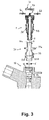
- the male tubular tip 1 shown in FIG. figure 1 present in known manner, at its axially outer end (ie upper), two branch connectors 2 and 3 in the form of fir tails which extend symmetrically on either side of two bearing surfaces 4a, 4b for the l the operator has this tip 1 and, at its axially inner end (ie lower), a circumferential groove 5 for receiving a seal O-ring 6 mounted or overmolded in this groove 5.
- two ramps 7a, 7b are formed radially projecting on a lower part of the male end 1 located above the groove 5 to provide a guide function and aid in locking, as will be explained below.
- the female tubular tip 10 (in particular visible at figure 3 ), of the cannula type and of standard shape, has essentially on its radially inner face 11, in the immediate vicinity of its axially outer inlet end 12 (ie upper), a circumferential connecting groove 13 which is of substantially trapezoidal axial section and which is intended to receive an axially inner connecting means 20 formed at a lower end of the device.
- the female endpiece 10 presents in addition, in the immediate vicinity of its axially inner end, a circumferential sealing zone 14 intended to receive the seal 6.
- the internal section of the female endpiece 10 has a constriction 15 axially below the groove 13 .
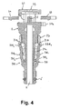
- the gripping plate 31 has a through hole 39 centered between the slots 31a, 31b which, when subjected to the axial thrust of an operator towards the female end in the direction of the arrow A for the obtaining the locking position illustrated in the figure 7 , not only its lights 31a, 31b filled by the underlying edge portions 32a, 32b but also the orifice 39 which is traversed flushly by an axial locking locking pin 8 extending between the two surfaces of support 4a, 4b of the male end 1 so that the pin 8 is visibly outcropping the outer face of the plate 31 to show the obtaining of the locking position (for example by a color of the tip 1 contrasting with that of the plate 31), being specified that this plate 31 then fills the recess 9 provided between the bearing surfaces 4a, 4b which are then located axially level with the plate 31.
- connecting lugs 21a, 21b it is possible to see figures 8 and 9 that they extend downwards respectively under two lower half-collars 33a, 33b of the main body 33 located below the notches 35a, 35b and that they are able to be locked in the locking position against the groove 13 by their bending generated by the respective ramps 7a, 7b for guiding and assisting with locking.
- each inner shoulder 33A, 33B terminates in a lower axial (ie vertical) flange 33A 1 , 33B 1 , which is perpendicular to this radial abutment interface and is adapted to be mounted in contact with the outer face of the arm 9A , 9B corresponding in this blocking position.
- each arm 9A, 9B has in a central zone of its external face (ie that which is turned away from the axis X of the nozzle 1) a same boss which is formed in this example of the invention of two protuberances 9A 1 , 9B 1 and 9A 2 , 9B 2 which are in the form of transverse ribs or teeth transverse to this arm 9A, 9B and which are interconnected by a surface slightly projecting outwards with respect to the rest of the arm 9A, 9B.
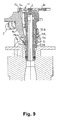
- Each boss is designed to cooperate by friction with an external chamfer 12a (ie upper) of the input end 12 of the socket 10 only when the male end 1 is fully depressed in this nozzle 10, and it is in particular each upper protuberance 9A 1 , 9B 1 , which is in this most prominent example which, when it rubs against the oblique surface of this chamfer 12a, optimizes the bending of the arms 9A, 9B by generating their folding parallel to the axis X of the tip 1 by tilting in the manner of 'a lever.
- the two protuberances 9A 1 , 9A 2 and 9B 1 , 9B 2 match the input chamfer 12a and 12b output of the input end 12 of the female end 10 they surround (see figure 6 ).
- the friction of each boss on the input end 12 of the female endpiece 10 has the effect of substantially increasing for the operator the driving force of the male endpiece 1 into the female endpiece 10 and this friction may furthermore generate an audible "click" type audible signal by the operator, this increased effort and / or this signal informing him of the obtaining of this correct insertion position of the male end-piece 1 into the female end 10, thus inviting him to maneuver at this precise moment the locking member 30 by pushing it towards the female end piece 10 to obtain the locking position.
- arms 9A, 9B also make it possible to angularly guide the tip 1 in translation in the socket 10 to facilitate the centering of the tabs 21a, 21b at the inlet of the connection groove 13 .
- connection device To unlock and disassemble the connection device out of the groove 13, it firstly pulls up on the locking member 30 while maintaining the male end 1 against the bottom of the female end piece 10, so as to extract from the latter the tabs 21a, 21b, then the male end 1 is extracted from the female endpiece 10.
Landscapes
- Engineering & Computer Science (AREA)
- General Engineering & Computer Science (AREA)
- Mechanical Engineering (AREA)
- Chemical & Material Sciences (AREA)
- Combustion & Propulsion (AREA)
- Quick-Acting Or Multi-Walled Pipe Joints (AREA)
Priority Applications (3)
| Application Number | Priority Date | Filing Date | Title |
|---|---|---|---|
| SI201230550A SI2500611T1 (sl) | 2011-03-15 | 2012-03-12 | Vezna naprava za prenos tekočine, vod, ki vključuje to napravo in metoda za montažo/demontažo le-te |
| RS20160330A RS54832B1 (sr) | 2011-03-15 | 2012-03-12 | Priključni uređaj za prenos fluida, kolo koje obuhvata taj uređaj i postupak za njegovo sklapanje/rasklapanje |
| PL12159051T PL2500611T3 (pl) | 2011-03-15 | 2012-03-12 | Urządzenie przyłączeniowe do linii przesyłowej płynu, obieg zawierający takie urządzenie oraz sposób jego montażu/demontażu |
Applications Claiming Priority (1)
| Application Number | Priority Date | Filing Date | Title |
|---|---|---|---|
| FR1152103A FR2972783B1 (fr) | 2011-03-15 | 2011-03-15 | Dispositif de raccordement pour transfert de fluide, circuit l'incorporant et son procede de montage/demontage. |
Publications (3)
| Publication Number | Publication Date |
|---|---|
| EP2500611A2 true EP2500611A2 (de) | 2012-09-19 |
| EP2500611A3 EP2500611A3 (de) | 2014-01-22 |
| EP2500611B1 EP2500611B1 (de) | 2016-02-24 |
Family
ID=45808331
Family Applications (1)
| Application Number | Title | Priority Date | Filing Date |
|---|---|---|---|
| EP12159051.7A Active EP2500611B1 (de) | 2011-03-15 | 2012-03-12 | Anschlussvorrichtung für den Transfer eines Fluids, Kreislauf, der diese Vorrichtung umfasst, und entsprechendes Montage-/Demontageverfahren |
Country Status (11)
| Country | Link |
|---|---|
| US (1) | US8777275B2 (de) |
| EP (1) | EP2500611B1 (de) |
| JP (1) | JP5988627B2 (de) |
| CN (1) | CN102705616A (de) |
| BR (1) | BR102012005725A2 (de) |
| ES (1) | ES2572000T3 (de) |
| FR (1) | FR2972783B1 (de) |
| MX (1) | MX2012003223A (de) |
| PL (1) | PL2500611T3 (de) |
| RS (1) | RS54832B1 (de) |
| SI (1) | SI2500611T1 (de) |
Cited By (2)
| Publication number | Priority date | Publication date | Assignee | Title |
|---|---|---|---|---|
| WO2015136161A1 (fr) * | 2014-03-12 | 2015-09-17 | A Raymond Et Cie | Dispositif de raccordement avec un verrou de connexion tournant |
| CN108139003A (zh) * | 2015-09-04 | 2018-06-08 | 生物梅里埃公司 | 用于将至少一个产物排放管连接到接收产物的装置的设备,例如来自提取核酸的仪器 |
Families Citing this family (7)
| Publication number | Priority date | Publication date | Assignee | Title |
|---|---|---|---|---|
| DE102010022304A1 (de) * | 2010-06-01 | 2011-12-01 | Veritas Ag | Schnellkupplung für Fluidleitungen |
| FR3004506B1 (fr) * | 2013-04-15 | 2015-11-06 | Sartorius Stedim Biotech | Connexion fluidique securisee. |
| US9689515B2 (en) * | 2013-11-06 | 2017-06-27 | Nifco Korea Inc. | Quick connector apparatus |
| US10746559B2 (en) | 2016-08-15 | 2020-08-18 | International Business Machines Corporation | Dynamic route guidance based on real-time data |
| US11061420B2 (en) * | 2019-04-01 | 2021-07-13 | Computime Ltd. | Mounting mechanism for thermostatic devices |
| JP2022526667A (ja) * | 2019-04-10 | 2022-05-25 | イー・アイ・デュポン・ドウ・ヌムール・アンド・カンパニー | ポリアミド組成物 |
| FR3098566B1 (fr) * | 2019-07-12 | 2021-06-11 | Hutchinson | Dispositif de raccordement fluidique |
Citations (2)
| Publication number | Priority date | Publication date | Assignee | Title |
|---|---|---|---|---|
| WO2007042344A1 (de) | 2005-10-10 | 2007-04-19 | Voss Automotive Gmbh | Steckverbinder für medienleitungen |
| EP2236894A1 (de) | 2009-03-05 | 2010-10-06 | Hutchinson | Kupplung für den Transport von Flüssigkeit und die damit verbundenen Verfahren zur Montage / Demontage |
Family Cites Families (4)
| Publication number | Priority date | Publication date | Assignee | Title |
|---|---|---|---|---|
| JPH06129583A (ja) * | 1992-10-19 | 1994-05-10 | Sekisui Chem Co Ltd | 管継手 |
| JP5051420B2 (ja) * | 2006-06-30 | 2012-10-17 | ニッタ株式会社 | 管継手 |
| FR2926869B1 (fr) * | 2008-01-25 | 2010-04-02 | Hutchinson | Dispositif de raccordement pour transfert de fluide,circuit l'incorporant et son procede de montage/demontage. |
| DE102009028473A1 (de) * | 2009-08-12 | 2011-02-17 | Robert Bosch Gmbh | Steckverbindung |
-
2011
- 2011-03-15 FR FR1152103A patent/FR2972783B1/fr not_active Expired - Fee Related
-
2012
- 2012-03-12 EP EP12159051.7A patent/EP2500611B1/de active Active
- 2012-03-12 RS RS20160330A patent/RS54832B1/sr unknown
- 2012-03-12 ES ES12159051T patent/ES2572000T3/es active Active
- 2012-03-12 US US13/418,135 patent/US8777275B2/en active Active
- 2012-03-12 PL PL12159051T patent/PL2500611T3/pl unknown
- 2012-03-12 SI SI201230550A patent/SI2500611T1/sl unknown
- 2012-03-14 JP JP2012056686A patent/JP5988627B2/ja not_active Expired - Fee Related
- 2012-03-14 CN CN2012100660958A patent/CN102705616A/zh active Pending
- 2012-03-14 BR BRBR102012005725-5A patent/BR102012005725A2/pt not_active Application Discontinuation
- 2012-03-15 MX MX2012003223A patent/MX2012003223A/es active IP Right Grant
Patent Citations (2)
| Publication number | Priority date | Publication date | Assignee | Title |
|---|---|---|---|---|
| WO2007042344A1 (de) | 2005-10-10 | 2007-04-19 | Voss Automotive Gmbh | Steckverbinder für medienleitungen |
| EP2236894A1 (de) | 2009-03-05 | 2010-10-06 | Hutchinson | Kupplung für den Transport von Flüssigkeit und die damit verbundenen Verfahren zur Montage / Demontage |
Cited By (3)
| Publication number | Priority date | Publication date | Assignee | Title |
|---|---|---|---|---|
| WO2015136161A1 (fr) * | 2014-03-12 | 2015-09-17 | A Raymond Et Cie | Dispositif de raccordement avec un verrou de connexion tournant |
| FR3018578A1 (fr) * | 2014-03-12 | 2015-09-18 | Raymond A & Cie | Dispositif de raccordement avec un verrou de connexion tournant |
| CN108139003A (zh) * | 2015-09-04 | 2018-06-08 | 生物梅里埃公司 | 用于将至少一个产物排放管连接到接收产物的装置的设备,例如来自提取核酸的仪器 |
Also Published As
| Publication number | Publication date |
|---|---|
| BR102012005725A2 (pt) | 2013-11-26 |
| US20120256414A1 (en) | 2012-10-11 |
| ES2572000T3 (es) | 2016-05-27 |
| JP2012193848A (ja) | 2012-10-11 |
| EP2500611A3 (de) | 2014-01-22 |
| RS54832B1 (sr) | 2016-10-31 |
| FR2972783B1 (fr) | 2013-03-22 |
| CN102705616A (zh) | 2012-10-03 |
| SI2500611T1 (sl) | 2016-09-30 |
| PL2500611T3 (pl) | 2016-08-31 |
| US8777275B2 (en) | 2014-07-15 |
| MX2012003223A (es) | 2012-09-27 |
| FR2972783A1 (fr) | 2012-09-21 |
| EP2500611B1 (de) | 2016-02-24 |
| JP5988627B2 (ja) | 2016-09-07 |
Similar Documents
| Publication | Publication Date | Title |
|---|---|---|
| EP2500611B1 (de) | Anschlussvorrichtung für den Transfer eines Fluids, Kreislauf, der diese Vorrichtung umfasst, und entsprechendes Montage-/Demontageverfahren | |
| EP2602531B1 (de) | Verriegelungsorgan einer Anschlussvorrichtung für den Transfer eines Fluids, diese Vorrichtung und ihr Verriegelungsverfahren | |
| EP2236894A1 (de) | Kupplung für den Transport von Flüssigkeit und die damit verbundenen Verfahren zur Montage / Demontage | |
| EP2439440B1 (de) | Anschlussvorrichtung mit Verriegelung durch Gewindegriffe, und Anschluss, der eine solche Vorrichtung enthält | |
| EP1752697B1 (de) | Kupplungsanordnung für einen Flüssigkeitskreislauf | |
| FR2945100A1 (fr) | Raccord encliquetable entre un conduit de fluide et un embout rigide avec un dispositif temoin de connexion et procede de controle de cette connexion | |
| EP3239581B1 (de) | Verschlussschieber für fluid-anschluss | |
| WO2006084969A1 (fr) | Dispositif de raccordement instantane avec moyen de verrouillage et/ou de deconnexion | |
| EP0911565A2 (de) | Schnellverbindung zur Verbindung von starren Rohren in einem Anschlussstück | |
| EP2908042A1 (de) | Bajonettverbindung zur lösbaren Verbindung von Kanalisationsrohren | |
| EP2752946B1 (de) | Elektrischer Anschluss mit automatischer Blockierung | |
| FR2894304A1 (fr) | Dispositif d'assemblage de deux plaques | |
| FR2715454A1 (fr) | Connexion rapide. | |
| EP2712652A2 (de) | Medizinisches Verbindungssystem mit Aufschraubblockierung | |
| EP2402640B1 (de) | Verschließbare Anschlussvorrichtung für den Transfer eines Fluids, und ihr Verschlussverfahren | |
| FR2910109A1 (fr) | Raccord rapide de canalisation. | |
| FR2795156A1 (fr) | Raccord encliquetable pour conduit de fluide, en particulier pour un circuit d'alimentation en carburant du moteur d'un vehicule automobile | |
| EP2101097B1 (de) | Anschlussvorrichtung für den Transfer eines Fluids, Kreislauf, der diese Vorrichtung umfasst, und entsprechendes Montage-/Demontageverfahren | |
| EP1972846B1 (de) | Schnellverbindungsvorrichtung zur Verbindung einer Flüssigkeitsleitung mit einer Steckverbindung, insbesondere für Kraftfahrzeug | |
| WO2015136161A1 (fr) | Dispositif de raccordement avec un verrou de connexion tournant | |
| EP2083206B1 (de) | Anschlussvorrichtung für den Transfer eines Fluids, Kreislauf, der diese Vorrichtung umfasst, und entsprechendes Montage-/Demontageverfahren | |
| EP2705873B1 (de) | Entfernbares Blockiersystem eines Katheters | |
| FR3061562B1 (fr) | Dispositif de raccordement amovible pour un guide de lumiere et application dans un vehicule automobile, module a transmission optique pourvu du dispositif | |
| EP0571286A1 (de) | Vorrichtung zum schnellen Verbinden von entweder einem rohrförmigen Element mit einem Rohrende oder einem System von rohrförmigen Elementen mit Rohrenden | |
| FR2899842A1 (fr) | Instrument d'ecriture comprenant une tete assemblee avec un corps et bloquee en rotation |
Legal Events
| Date | Code | Title | Description |
|---|---|---|---|
| PUAI | Public reference made under article 153(3) epc to a published international application that has entered the european phase |
Free format text: ORIGINAL CODE: 0009012 |
|
| AK | Designated contracting states |
Kind code of ref document: A2 Designated state(s): AL AT BE BG CH CY CZ DE DK EE ES FI FR GB GR HR HU IE IS IT LI LT LU LV MC MK MT NL NO PL PT RO RS SE SI SK SM TR |
|
| AX | Request for extension of the european patent |
Extension state: BA ME |
|
| PUAL | Search report despatched |
Free format text: ORIGINAL CODE: 0009013 |
|
| AK | Designated contracting states |
Kind code of ref document: A3 Designated state(s): AL AT BE BG CH CY CZ DE DK EE ES FI FR GB GR HR HU IE IS IT LI LT LU LV MC MK MT NL NO PL PT RO RS SE SI SK SM TR |
|
| AX | Request for extension of the european patent |
Extension state: BA ME |
|
| RIC1 | Information provided on ipc code assigned before grant |
Ipc: F02M 55/00 20060101ALI20131216BHEP Ipc: F16L 37/133 20060101ALI20131216BHEP Ipc: F16L 37/098 20060101AFI20131216BHEP |
|
| 17P | Request for examination filed |
Effective date: 20140722 |
|
| RBV | Designated contracting states (corrected) |
Designated state(s): AL AT BE BG CH CY CZ DE DK EE ES FI FR GB GR HR HU IE IS IT LI LT LU LV MC MK MT NL NO PL PT RO RS SE SI SK SM TR |
|
| GRAP | Despatch of communication of intention to grant a patent |
Free format text: ORIGINAL CODE: EPIDOSNIGR1 |
|
| INTG | Intention to grant announced |
Effective date: 20150818 |
|
| GRAS | Grant fee paid |
Free format text: ORIGINAL CODE: EPIDOSNIGR3 |
|
| GRAA | (expected) grant |
Free format text: ORIGINAL CODE: 0009210 |
|
| AK | Designated contracting states |
Kind code of ref document: B1 Designated state(s): AL AT BE BG CH CY CZ DE DK EE ES FI FR GB GR HR HU IE IS IT LI LT LU LV MC MK MT NL NO PL PT RO RS SE SI SK SM TR |
|
| REG | Reference to a national code |
Ref country code: GB Ref legal event code: FG4D Free format text: NOT ENGLISH |
|
| REG | Reference to a national code |
Ref country code: CH Ref legal event code: EP |
|
| REG | Reference to a national code |
Ref country code: AT Ref legal event code: REF Ref document number: 776912 Country of ref document: AT Kind code of ref document: T Effective date: 20160315 |
|
| REG | Reference to a national code |
Ref country code: IE Ref legal event code: FG4D Free format text: LANGUAGE OF EP DOCUMENT: FRENCH |
|
| REG | Reference to a national code |
Ref country code: DE Ref legal event code: R096 Ref document number: 602012014829 Country of ref document: DE |
|
| REG | Reference to a national code |
Ref country code: FR Ref legal event code: PLFP Year of fee payment: 5 |
|
| REG | Reference to a national code |
Ref country code: ES Ref legal event code: FG2A Ref document number: 2572000 Country of ref document: ES Kind code of ref document: T3 Effective date: 20160527 |
|
| REG | Reference to a national code |
Ref country code: SE Ref legal event code: TRGR |
|
| REG | Reference to a national code |
Ref country code: LT Ref legal event code: MG4D |
|
| REG | Reference to a national code |
Ref country code: NL Ref legal event code: MP Effective date: 20160224 |
|
| REG | Reference to a national code |
Ref country code: AT Ref legal event code: MK05 Ref document number: 776912 Country of ref document: AT Kind code of ref document: T Effective date: 20160224 |
|
| PG25 | Lapsed in a contracting state [announced via postgrant information from national office to epo] |
Ref country code: GR Free format text: LAPSE BECAUSE OF FAILURE TO SUBMIT A TRANSLATION OF THE DESCRIPTION OR TO PAY THE FEE WITHIN THE PRESCRIBED TIME-LIMIT Effective date: 20160525 Ref country code: NO Free format text: LAPSE BECAUSE OF FAILURE TO SUBMIT A TRANSLATION OF THE DESCRIPTION OR TO PAY THE FEE WITHIN THE PRESCRIBED TIME-LIMIT Effective date: 20160524 Ref country code: FI Free format text: LAPSE BECAUSE OF FAILURE TO SUBMIT A TRANSLATION OF THE DESCRIPTION OR TO PAY THE FEE WITHIN THE PRESCRIBED TIME-LIMIT Effective date: 20160224 Ref country code: HR Free format text: LAPSE BECAUSE OF FAILURE TO SUBMIT A TRANSLATION OF THE DESCRIPTION OR TO PAY THE FEE WITHIN THE PRESCRIBED TIME-LIMIT Effective date: 20160224 |
|
| PG25 | Lapsed in a contracting state [announced via postgrant information from national office to epo] |
Ref country code: PT Free format text: LAPSE BECAUSE OF FAILURE TO SUBMIT A TRANSLATION OF THE DESCRIPTION OR TO PAY THE FEE WITHIN THE PRESCRIBED TIME-LIMIT Effective date: 20160624 Ref country code: LT Free format text: LAPSE BECAUSE OF FAILURE TO SUBMIT A TRANSLATION OF THE DESCRIPTION OR TO PAY THE FEE WITHIN THE PRESCRIBED TIME-LIMIT Effective date: 20160224 Ref country code: LV Free format text: LAPSE BECAUSE OF FAILURE TO SUBMIT A TRANSLATION OF THE DESCRIPTION OR TO PAY THE FEE WITHIN THE PRESCRIBED TIME-LIMIT Effective date: 20160224 Ref country code: NL Free format text: LAPSE BECAUSE OF FAILURE TO SUBMIT A TRANSLATION OF THE DESCRIPTION OR TO PAY THE FEE WITHIN THE PRESCRIBED TIME-LIMIT Effective date: 20160224 Ref country code: BE Free format text: LAPSE BECAUSE OF NON-PAYMENT OF DUE FEES Effective date: 20160331 Ref country code: AT Free format text: LAPSE BECAUSE OF FAILURE TO SUBMIT A TRANSLATION OF THE DESCRIPTION OR TO PAY THE FEE WITHIN THE PRESCRIBED TIME-LIMIT Effective date: 20160224 |
|
| REG | Reference to a national code |
Ref country code: SK Ref legal event code: T3 Ref document number: E 20939 Country of ref document: SK |
|
| PG25 | Lapsed in a contracting state [announced via postgrant information from national office to epo] |
Ref country code: EE Free format text: LAPSE BECAUSE OF FAILURE TO SUBMIT A TRANSLATION OF THE DESCRIPTION OR TO PAY THE FEE WITHIN THE PRESCRIBED TIME-LIMIT Effective date: 20160224 Ref country code: DK Free format text: LAPSE BECAUSE OF FAILURE TO SUBMIT A TRANSLATION OF THE DESCRIPTION OR TO PAY THE FEE WITHIN THE PRESCRIBED TIME-LIMIT Effective date: 20160224 |
|
| REG | Reference to a national code |
Ref country code: CH Ref legal event code: PL |
|
| REG | Reference to a national code |
Ref country code: DE Ref legal event code: R097 Ref document number: 602012014829 Country of ref document: DE |
|
| PG25 | Lapsed in a contracting state [announced via postgrant information from national office to epo] |
Ref country code: SM Free format text: LAPSE BECAUSE OF FAILURE TO SUBMIT A TRANSLATION OF THE DESCRIPTION OR TO PAY THE FEE WITHIN THE PRESCRIBED TIME-LIMIT Effective date: 20160224 Ref country code: RO Free format text: LAPSE BECAUSE OF FAILURE TO SUBMIT A TRANSLATION OF THE DESCRIPTION OR TO PAY THE FEE WITHIN THE PRESCRIBED TIME-LIMIT Effective date: 20160224 |
|
| REG | Reference to a national code |
Ref country code: IE Ref legal event code: MM4A |
|
| PLBE | No opposition filed within time limit |
Free format text: ORIGINAL CODE: 0009261 |
|
| STAA | Information on the status of an ep patent application or granted ep patent |
Free format text: STATUS: NO OPPOSITION FILED WITHIN TIME LIMIT |
|
| PG25 | Lapsed in a contracting state [announced via postgrant information from national office to epo] |
Ref country code: IE Free format text: LAPSE BECAUSE OF NON-PAYMENT OF DUE FEES Effective date: 20160312 Ref country code: CH Free format text: LAPSE BECAUSE OF NON-PAYMENT OF DUE FEES Effective date: 20160331 Ref country code: LI Free format text: LAPSE BECAUSE OF NON-PAYMENT OF DUE FEES Effective date: 20160331 |
|
| 26N | No opposition filed |
Effective date: 20161125 |
|
| REG | Reference to a national code |
Ref country code: FR Ref legal event code: PLFP Year of fee payment: 6 |
|
| PG25 | Lapsed in a contracting state [announced via postgrant information from national office to epo] |
Ref country code: BG Free format text: LAPSE BECAUSE OF FAILURE TO SUBMIT A TRANSLATION OF THE DESCRIPTION OR TO PAY THE FEE WITHIN THE PRESCRIBED TIME-LIMIT Effective date: 20160524 |
|
| PG25 | Lapsed in a contracting state [announced via postgrant information from national office to epo] |
Ref country code: MT Free format text: LAPSE BECAUSE OF FAILURE TO SUBMIT A TRANSLATION OF THE DESCRIPTION OR TO PAY THE FEE WITHIN THE PRESCRIBED TIME-LIMIT Effective date: 20160224 |
|
| REG | Reference to a national code |
Ref country code: FR Ref legal event code: PLFP Year of fee payment: 7 |
|
| PG25 | Lapsed in a contracting state [announced via postgrant information from national office to epo] |
Ref country code: HU Free format text: LAPSE BECAUSE OF FAILURE TO SUBMIT A TRANSLATION OF THE DESCRIPTION OR TO PAY THE FEE WITHIN THE PRESCRIBED TIME-LIMIT; INVALID AB INITIO Effective date: 20120312 Ref country code: CY Free format text: LAPSE BECAUSE OF FAILURE TO SUBMIT A TRANSLATION OF THE DESCRIPTION OR TO PAY THE FEE WITHIN THE PRESCRIBED TIME-LIMIT Effective date: 20160224 |
|
| PG25 | Lapsed in a contracting state [announced via postgrant information from national office to epo] |
Ref country code: LU Free format text: LAPSE BECAUSE OF NON-PAYMENT OF DUE FEES Effective date: 20160312 Ref country code: MC Free format text: LAPSE BECAUSE OF FAILURE TO SUBMIT A TRANSLATION OF THE DESCRIPTION OR TO PAY THE FEE WITHIN THE PRESCRIBED TIME-LIMIT Effective date: 20160224 Ref country code: IS Free format text: LAPSE BECAUSE OF FAILURE TO SUBMIT A TRANSLATION OF THE DESCRIPTION OR TO PAY THE FEE WITHIN THE PRESCRIBED TIME-LIMIT Effective date: 20160224 Ref country code: MK Free format text: LAPSE BECAUSE OF FAILURE TO SUBMIT A TRANSLATION OF THE DESCRIPTION OR TO PAY THE FEE WITHIN THE PRESCRIBED TIME-LIMIT Effective date: 20160224 |
|
| PG25 | Lapsed in a contracting state [announced via postgrant information from national office to epo] |
Ref country code: AL Free format text: LAPSE BECAUSE OF FAILURE TO SUBMIT A TRANSLATION OF THE DESCRIPTION OR TO PAY THE FEE WITHIN THE PRESCRIBED TIME-LIMIT Effective date: 20160224 |
|
| PGFP | Annual fee paid to national office [announced via postgrant information from national office to epo] |
Ref country code: RS Payment date: 20210308 Year of fee payment: 10 Ref country code: SE Payment date: 20210319 Year of fee payment: 10 Ref country code: SI Payment date: 20210310 Year of fee payment: 10 |
|
| PGFP | Annual fee paid to national office [announced via postgrant information from national office to epo] |
Ref country code: SK Payment date: 20210310 Year of fee payment: 10 |
|
| PGFP | Annual fee paid to national office [announced via postgrant information from national office to epo] |
Ref country code: TR Payment date: 20220311 Year of fee payment: 11 |
|
| PGFP | Annual fee paid to national office [announced via postgrant information from national office to epo] |
Ref country code: ES Payment date: 20220527 Year of fee payment: 11 |
|
| REG | Reference to a national code |
Ref country code: SK Ref legal event code: MM4A Ref document number: E 20939 Country of ref document: SK Effective date: 20220312 |
|
| PG25 | Lapsed in a contracting state [announced via postgrant information from national office to epo] |
Ref country code: RS Free format text: LAPSE BECAUSE OF NON-PAYMENT OF DUE FEES Effective date: 20220312 |
|
| REG | Reference to a national code |
Ref country code: SI Ref legal event code: KO00 Effective date: 20221122 |
|
| PG25 | Lapsed in a contracting state [announced via postgrant information from national office to epo] |
Ref country code: SK Free format text: LAPSE BECAUSE OF NON-PAYMENT OF DUE FEES Effective date: 20220312 Ref country code: SE Free format text: LAPSE BECAUSE OF NON-PAYMENT OF DUE FEES Effective date: 20220313 |
|
| PG25 | Lapsed in a contracting state [announced via postgrant information from national office to epo] |
Ref country code: SI Free format text: LAPSE BECAUSE OF NON-PAYMENT OF DUE FEES Effective date: 20220313 |
|
| PGFP | Annual fee paid to national office [announced via postgrant information from national office to epo] |
Ref country code: FR Payment date: 20230324 Year of fee payment: 12 Ref country code: CZ Payment date: 20230306 Year of fee payment: 12 |
|
| PGFP | Annual fee paid to national office [announced via postgrant information from national office to epo] |
Ref country code: PL Payment date: 20230303 Year of fee payment: 12 Ref country code: GB Payment date: 20230321 Year of fee payment: 12 |
|
| P01 | Opt-out of the competence of the unified patent court (upc) registered |
Effective date: 20230526 |
|
| PGFP | Annual fee paid to national office [announced via postgrant information from national office to epo] |
Ref country code: IT Payment date: 20230328 Year of fee payment: 12 |
|
| PGFP | Annual fee paid to national office [announced via postgrant information from national office to epo] |
Ref country code: DE Payment date: 20240320 Year of fee payment: 13 |
|
| REG | Reference to a national code |
Ref country code: ES Ref legal event code: FD2A Effective date: 20240506 |