EP2500568A2 - Bohrlochrückschlagverzögerer für eine Exzenterschneckenpumpe - Google Patents
Bohrlochrückschlagverzögerer für eine Exzenterschneckenpumpe Download PDFInfo
- Publication number
- EP2500568A2 EP2500568A2 EP12159519A EP12159519A EP2500568A2 EP 2500568 A2 EP2500568 A2 EP 2500568A2 EP 12159519 A EP12159519 A EP 12159519A EP 12159519 A EP12159519 A EP 12159519A EP 2500568 A2 EP2500568 A2 EP 2500568A2
- Authority
- EP
- European Patent Office
- Prior art keywords
- retarder
- impeller
- drive
- downhole
- shaft
- Prior art date
- Legal status (The legal status is an assumption and is not a legal conclusion. Google has not performed a legal analysis and makes no representation as to the accuracy of the status listed.)
- Granted
Links
- 239000012530 fluid Substances 0.000 claims abstract description 42
- 230000000750 progressive effect Effects 0.000 claims abstract description 12
- 238000000034 method Methods 0.000 claims description 8
- 230000008878 coupling Effects 0.000 claims description 7
- 238000010168 coupling process Methods 0.000 claims description 7
- 238000005859 coupling reaction Methods 0.000 claims description 7
- 230000000979 retarding effect Effects 0.000 claims description 5
- 238000005086 pumping Methods 0.000 claims description 4
- 230000013011 mating Effects 0.000 claims 1
- 230000000295 complement effect Effects 0.000 description 3
- 239000000463 material Substances 0.000 description 3
- 239000003082 abrasive agent Substances 0.000 description 2
- 230000000694 effects Effects 0.000 description 2
- 238000004519 manufacturing process Methods 0.000 description 2
- 230000007246 mechanism Effects 0.000 description 2
- 239000002184 metal Substances 0.000 description 2
- 238000009987 spinning Methods 0.000 description 2
- 229910000831 Steel Inorganic materials 0.000 description 1
- 238000005299 abrasion Methods 0.000 description 1
- 230000004075 alteration Effects 0.000 description 1
- 230000009286 beneficial effect Effects 0.000 description 1
- 230000000903 blocking effect Effects 0.000 description 1
- 239000003990 capacitor Substances 0.000 description 1
- 239000002131 composite material Substances 0.000 description 1
- 230000001627 detrimental effect Effects 0.000 description 1
- 238000006073 displacement reaction Methods 0.000 description 1
- 230000009977 dual effect Effects 0.000 description 1
- 230000017525 heat dissipation Effects 0.000 description 1
- 230000006698 induction Effects 0.000 description 1
- 230000003993 interaction Effects 0.000 description 1
- 238000003754 machining Methods 0.000 description 1
- 238000012423 maintenance Methods 0.000 description 1
- 239000007769 metal material Substances 0.000 description 1
- 238000012986 modification Methods 0.000 description 1
- 230000004048 modification Effects 0.000 description 1
- 238000000465 moulding Methods 0.000 description 1
- 229920000642 polymer Polymers 0.000 description 1
- 230000002250 progressing effect Effects 0.000 description 1
- 239000004576 sand Substances 0.000 description 1
- 238000010561 standard procedure Methods 0.000 description 1
- 239000010959 steel Substances 0.000 description 1
- 239000000725 suspension Substances 0.000 description 1
- 238000003466 welding Methods 0.000 description 1
Images



Classifications
-
- F—MECHANICAL ENGINEERING; LIGHTING; HEATING; WEAPONS; BLASTING
- F04—POSITIVE - DISPLACEMENT MACHINES FOR LIQUIDS; PUMPS FOR LIQUIDS OR ELASTIC FLUIDS
- F04C—ROTARY-PISTON, OR OSCILLATING-PISTON, POSITIVE-DISPLACEMENT MACHINES FOR LIQUIDS; ROTARY-PISTON, OR OSCILLATING-PISTON, POSITIVE-DISPLACEMENT PUMPS
- F04C2/00—Rotary-piston machines or pumps
- F04C2/08—Rotary-piston machines or pumps of intermeshing-engagement type, i.e. with engagement of co-operating members similar to that of toothed gearing
- F04C2/10—Rotary-piston machines or pumps of intermeshing-engagement type, i.e. with engagement of co-operating members similar to that of toothed gearing of internal-axis type with the outer member having more teeth or tooth-equivalents, e.g. rollers, than the inner member
- F04C2/107—Rotary-piston machines or pumps of intermeshing-engagement type, i.e. with engagement of co-operating members similar to that of toothed gearing of internal-axis type with the outer member having more teeth or tooth-equivalents, e.g. rollers, than the inner member with helical teeth
- F04C2/1071—Rotary-piston machines or pumps of intermeshing-engagement type, i.e. with engagement of co-operating members similar to that of toothed gearing of internal-axis type with the outer member having more teeth or tooth-equivalents, e.g. rollers, than the inner member with helical teeth the inner and outer member having a different number of threads and one of the two being made of elastic materials, e.g. Moineau type
-
- E—FIXED CONSTRUCTIONS
- E21—EARTH OR ROCK DRILLING; MINING
- E21B—EARTH OR ROCK DRILLING; OBTAINING OIL, GAS, WATER, SOLUBLE OR MELTABLE MATERIALS OR A SLURRY OF MINERALS FROM WELLS
- E21B43/00—Methods or apparatus for obtaining oil, gas, water, soluble or meltable materials or a slurry of minerals from wells
- E21B43/12—Methods or apparatus for controlling the flow of the obtained fluid to or in wells
- E21B43/121—Lifting well fluids
- E21B43/126—Adaptations of down-hole pump systems powered by drives outside the borehole, e.g. by a rotary or oscillating drive
-
- F—MECHANICAL ENGINEERING; LIGHTING; HEATING; WEAPONS; BLASTING
- F04—POSITIVE - DISPLACEMENT MACHINES FOR LIQUIDS; PUMPS FOR LIQUIDS OR ELASTIC FLUIDS
- F04C—ROTARY-PISTON, OR OSCILLATING-PISTON, POSITIVE-DISPLACEMENT MACHINES FOR LIQUIDS; ROTARY-PISTON, OR OSCILLATING-PISTON, POSITIVE-DISPLACEMENT PUMPS
- F04C13/00—Adaptations of machines or pumps for special use, e.g. for extremely high pressures
- F04C13/008—Pumps for submersible use, i.e. down-hole pumping
-
- F—MECHANICAL ENGINEERING; LIGHTING; HEATING; WEAPONS; BLASTING
- F04—POSITIVE - DISPLACEMENT MACHINES FOR LIQUIDS; PUMPS FOR LIQUIDS OR ELASTIC FLUIDS
- F04C—ROTARY-PISTON, OR OSCILLATING-PISTON, POSITIVE-DISPLACEMENT MACHINES FOR LIQUIDS; ROTARY-PISTON, OR OSCILLATING-PISTON, POSITIVE-DISPLACEMENT PUMPS
- F04C14/00—Control of, monitoring of, or safety arrangements for, machines, pumps or pumping installations
- F04C14/28—Safety arrangements; Monitoring
-
- F—MECHANICAL ENGINEERING; LIGHTING; HEATING; WEAPONS; BLASTING
- F04—POSITIVE - DISPLACEMENT MACHINES FOR LIQUIDS; PUMPS FOR LIQUIDS OR ELASTIC FLUIDS
- F04C—ROTARY-PISTON, OR OSCILLATING-PISTON, POSITIVE-DISPLACEMENT MACHINES FOR LIQUIDS; ROTARY-PISTON, OR OSCILLATING-PISTON, POSITIVE-DISPLACEMENT PUMPS
- F04C15/00—Component parts, details or accessories of machines, pumps or pumping installations, not provided for in groups F04C2/00 - F04C14/00
- F04C15/0057—Driving elements, brakes, couplings, transmission specially adapted for machines or pumps
- F04C15/0061—Means for transmitting movement from the prime mover to driven parts of the pump, e.g. clutches, couplings, transmissions
- F04C15/0073—Couplings between rotors and input or output shafts acting by interengaging or mating parts, i.e. positive coupling of rotor and shaft
Definitions
- PCP Progressive cavity pump
- the PCP systems have a drive head at the surface and a rotor and stator downhole.
- the drive head rotates a rod string that turns the rotor in the stator. This lifts a fluid column up a tubing string to be produced at the surface.
- the PCP systems tend to store energy in the rod string and the lifted column of fluid. This stored energy can be problematic if the release of the energy is not controlled properly when the well is shut off.
- Various breaking and decelerating devices have been developed for surface drive heads to control the release of the stored energy. Unfortunately, current devices can be expensive and may not be effective in every situation.
- One downhole device for dealing with the stored energy uses a dump valve to direct fluid out of the tubing to the annulus. When opened, the dump valve prevents the column of fluid from going through the pump and generating hydraulic energy that causes backspin on the rod string.
- Another downhole device uses a check valve at the pump intake. The check valve holds the weight of the fluid column above the pump and keeps it from going through the pump and generating the hydraulic energy that causes backspin on the rod string.
- the most common devices to control the release of the stored energy are used at the surface.
- Various surface devices can use braking to control the release of stored energy in the rod string.
- the braking can use direct mechanical braking, hydraulic braking, centrifugal braking, or the like at the surface drive head.
- one major limitation to the surface devices is their inability to dissipate the tremendous amount of heat that they can produce.
- the ISO standard for PCP drive heads may require a temperature below a certain limit (e.g ., 150°C) during backspin.
- the defined limit can eliminate the feasibility of using certain braking devices due to the large amount of energy that could potentially be stored in the fluid column filling the tubing.
- VSD variable speed driver
- the surface device may use a small choke in a hydraulic brake.
- the subject matter of the present disclosure is directed to overcoming, or at least reducing the effects of, one or more of the problems set forth above.
- a backspin retarder is used for a progressive cavity pump.
- the progressive cavity pump has a drive unit that imparts rotation to a drive string disposed in a tubing string.
- the progressive cavity pump has a pump unit coupled to the rotation of the drive string. As the pump unit operates, it lifts a column of produced fluid up the tubing string.
- the backspin retarder can deploy on the drive string in a number of positions, including deploying at some point uphole from the pump unit, deploying below the pump as an extension of the rotor, deploying between two pumps ( e.g ., tandem or charge pumps), or deploying in a combination of these positions.
- the backspin retarder can be used alone or in combination with a braking system or other device at the surface that controls backspin of the drive string.
- the backspin retarder has a shaft and an impeller.
- the shaft connects to portions of a drive string for the progressive cavity pump, and the shaft can have rod connectors for coupling to sections of sucker rod or the like using couplings, for example.
- the impeller disposes on the shaft and can rotate and move axially thereon.
- the impeller can have a plurality of vanes that run straight along the impeller or have a counter-clockwise twist along the impeller's length.
- the impeller can have engaged and disengaged conditions relative thereto.
- the impeller has the disengaged condition at least when the shaft rotates in a drive (e.g ., clockwise) direction.
- a drive e.g ., clockwise
- fluid downhole of the impeller flowing uphole past the impeller also tends to disengage the impeller.
- the impeller and shaft can rotate relative to one another. This allows the drive string to rotate in the drive direction while the impeller remains stationary relative to the tubing string, although the impeller may rotate even in the counterclockwise direction.
- the impeller rotates with the shaft to retard backspin of the drive string using drag from the impeller's vanes.
- the impeller has the engaged condition at least when the shaft rotates in a backspin (e.g ., counter-clockwise) direction.
- the pump does not lift fluid so lifted fluid uphole of the impeller flows downhole past the impeller.
- the impeller tends to move to the engaged condition so that it will rotate with the shaft and drive string.
- the shape and dimensions of the vanes and impeller can be designed to favor engagement and the retarding effect.
- the retarder can use a number of mechanisms to engage and disengage the impeller to the rotation of the shaft depending on whether the core shaft is rotating in the drive direction or the backspin direction.
- the impeller defines one or more slots in an internal bore of the impeller
- the shaft has one or more pins or set of pins for disposing in the one or more slots.
- the pins can be arranged radially or axially on the shaft.
- Each slot defines a circumferential or free wheel section defined around the internal bore and defines at least one catch section extending therefrom.
- Each pin disposes in the circumferential section when the impeller has the disengaged condition so that the pin can move in the circumferential section freely as the shaft rotates relative to the impeller.
- the shaft's pin disposes in the at least one catch section, however, when the impeller has the engaged condition. In this instance, the pin enters the at least one catch section when the impeller moves downhole on the shaft and the shaft rotates in the backspin direction. With the pin in the catch section, the impeller can rotate with the shaft in the backspin direction to produce the desired drag.
- the shaft has shoulders uphole and downhole of the impeller that limit axial movement of the impeller thereon.
- the downhole shoulder can engage the downhole end of the impellers in the engaged condition so the impeller rotates with the shaft.
- the downhole shoulder and end can have corresponding teeth that permit clockwise rotation relative thereto, but that restrict counter-clockwise rotation.
- multiple forms of engagement can be used together on the impeller.
- engagement from a downhole shoulder can be used in conjunction with engagement from one or more internal pin/slot arrangements. These and other forms of engagement can be used.
- Figs. 1A-1C illustrate a progressive cavity pump system having downhole backspin retarders according to the present disclosure.
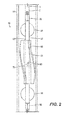
- Fig. 2 shows a backspin retarder in isolated detail.
- Fig. 3 shows a perspective view of an external impeller of the backspin retarder.
- Fig. 4 shows a cross-sectional view of the external impeller and its internal groove.
- Fig. 5 shows a partial cross-section of the core shaft and pin.
- Figs. 6A-6B show the backspin retarder in two stages of operation.
- Figs. 7A-7B show alternate arrangements for the disclosed backspin retarder.
- Figs. 8A-8B show another downhole backspin retarder in two stages of operation using another form of engagement.
- Figs. 9A-9B show yet another form of engagement for the impeller and core shaft of the disclosed retarder.
- Figs. 10A-10B show arrangements for biasing the impeller on the core shaft.
- Fig. 11 shown an alternative arrangement for biasing and engaging the impeller and core shaft.
- Fig. 12 show additional features to facilitate and protect rotation between the impeller and core shaft.
- a progressive cavity pump system 10 shown in Figure 1A is used for a wellhead 12.
- the progressing cavity pump system 10 has a surface drive 20, a drive string 30, and a downhole progressive cavity pump unit 40.
- the surface drive 20 has a drive head 22 mounted above the wellhead 12 and has an electric or hydraulic motor 24 coupled to the drive head 22 by a pulley/belt or gearbox assembly 26.
- the drive head 22 typically includes a stuffing box 25, a clamp 28, and a polished rod 29.
- the stuffing box 25 is used to seal the connection of the drive head 20 to the drive string 30, and the clamp 28 and the polished rod 29 are used to transmit the rotation from the drive head 22 to the drive shaft 30.
- the pump unit 40 installs below the wellhead 12 at a substantial depth (e.g ., about 2000 m) in the wellbore.
- the pump unit 40 has a single helical-shaped rotor 42 that turns inside a double helical elastomer-lined stator 44.
- the stator 44 attached to the production tubing string 14 remains stationary, and the surface drive 20 coupled to the rotor 42 by the drive string 30 causes the rotor 42 to turn eccentrically in the stator 44.
- a series of sealed cavities form between the stator 42 and the rotor 44 and progress from the inlet end to the discharge end of the pump unit 40, which produces a non-pulsating positive displacement flow.
- the drive string 30 coupled to the rotor 42 is typically a steel stem having a diameter of approximately 1" and a length sufficient for the required operations. During pumping, the string 30 may be wound torsionally several dozen times so that the string 30 accumulates a substantial amount of stored energy. In addition, the height of the fluid column above the pump unit 40 can produce hydraulic energy on the drive string 30 while the pump unit 40 is producing. This hydraulic energy increases the energy of the twisted string 30 because it causes the pump unit 40 to operate as a hydraulic motor, rotating in the same direction as the twisting of the drive string 30.
- a braking system (not shown) in the drive 20 is responsible for blocking and/or controlling the reverse speed resulting from suspension of the operations. When pumping is stopped, for example, the braking system is activated to block and/or allow reverse speed control and dissipate all of the energy accumulated on the string 30. Otherwise, the pulleys or gears of the assembly 26 would disintegrate or become damaged due to the centrifugal force generated by the high rotation that would occur without the braking system.
- the braking system can have a brake screw 23 that can be operated directly by an operator. Turning the brake screw 23 can apply or release an internal brake shoe that, in turn, presses on a rotating drum, causing a braking effect to string 30.
- Other braking systems based on hydraulics, centrifugal force, and the like can also be used.
- the system 10 has one or more downhole retarders 50 that install at various locations along the drill string 30.
- the retarders 50 release stored energy of the drill string 30 downhole in the well as opposed to having the surface braking system exclusively release the energy at the surface. As detailed below, this has a number of benefits for progressive cavity pump operations.
- one or more retarders 50A can install on the drive string 30 above the pump unit 40.
- one or more other retarders 50B can be used in addition or as an alternative to the retarders 50A above the pump unit 40, and these retarders 50B can deploy below the pump unit 40 as an extension of the rotor 42.
- one or more retarders 50C as in Figure 1C can deploy between two pump units 40 ( e.g ., tandem or charge pumps). These and other arrangements are possible.
- the disclosed retarder 50 uses fluid momentum and drag force to retard backspin produced in the drive string 30 at least when the drive string 30 stops rotation in its drive direction. By retarding the backspin, the retarder 50 can then reduce the amount of stored energy that must be handled by the surface braking system. Overall, this retarding of backspin can reduce the amount of heat that must be dissipated at the surface. Likewise, the backspin retarding can decrease the amount of time it takes to deal with the stored energy at the surface.
- the retarder 50 may have any suitable length along the drive string 30. Although a few retarders 50A-C are shown in Figures 1A-1C , multiple retarders 50 can be disposed at various points along the length of the drive string 30. Use of such multiple retarders 50 may be beneficial in some implementations because the retarders 50 can control backspin of the drive string 30 at strategic points along the string 30.
- a retarder 50 has a core shaft 52 that attaches to the rod string with connector ends 56.
- the core shaft 52 can be a sucker rod section, and the connector ends 56 can have flats and threaded couplings.
- the connector ends 56 can connect to couplings C and upper and lower sucker rods R using standard techniques.
- Any suitable form of centralizer 54 for drive strings can be used on the core shaft 52 to help stabilize the assembly.
- a set of pins 80 extend radially outward from the core shaft 52, and an external impeller 60 of the retarder 50 installs on the core shaft 52 at the location of the pins.
- the core shaft 52 is preferably composed of suitable metal material.
- the impeller 60 various materials can be used, such as polymer, composite, metal, or the like, and the impeller 60 can be formed by machining, molding, and the like.
- the impeller 60 can use a combination of materials to improve performance. For example, some parts can be composed of metal to achieve strength, while others can be composed of plastic to reduce weight.
- the central bore 62 has a slot 70 for the pins 80 on the core shaft 52. If desirable, bearings and/or seals (not shown) can be provided between the impeller's central bore 62 and the core shaft 52 as described later.
- the impeller 60 is equipped with vanes, blades, or fins 64. As shown in Figure 3 , for example, the impeller 60 can have three helical vanes 64 wound in a counter-clockwise twist along the length of the impeller 60. However, the shape and orientation of the vanes 64 can depend on the particular implementation. For example, more or less vanes 64 can be used, and the vanes 64 can be straight or twist along the length of the impeller 60 in any suitable fashion.
- the impeller 60 can rotate on the core shaft 52 and can shift axially as well, but the arrangement of pins 80 and slot 70 limit the impeller's movement.
- the rotation of the shaft 52 and the flow of fluid past the vanes 64 further dictates the movement of the impeller 60, and provided in more detail below.
- the retarder 50 releases stored energy of the drive string downhole in the well.
- interaction of the impeller 60 with fluid in the tubing 14 and the core shaft 52 accomplishes this release of energy.
- the core shaft 52 When installed on a rod string, the core shaft 52 rotates as part of the rod string. Independently, the impeller 60 engages and disengages from the core shaft 52 using the pins 80 and slot 70. Whether the impeller 60 is engaged or disengaged is based on a combination of axial and rotational drag forces. For example, backwards flow of fluid during recoil (backspin) engages the impeller 60 with the shaft 52 so that the impeller rotates and pumps against the fluid equalization. In this way, the draft from the retarder's impeller 60 can enhance the release of backspin energy when used alone or in combination with other devices to release stored energy.
- backspin backwards flow of fluid during recoil
- the length of the impeller 60 (and hence the resulting torque and energy release produced) can depend on the implementation. As one example, the impeller 60 can have a length of about 3-ft to about 10-ft.
- the vanes 60 can extend toward the surrounding tubing 14, but preferably avoid direct contact with the tubing's inner wall.
- the slot 70 for the impeller 60 has a free wheel channel 72 defined circumferentially around the central bore 62 of the impeller 60.
- the slot 70 also has angled catches 74 (one for each of the pins 80) on opposing sides of the bore 62. These angled catches 74 incline in an uphole and counter-clockwise manner in the inside surface of the bore 62 from the free wheel channel 72.
- the slot 70 can be formed inside the internal bore 62 in a number of ways.
- the slot 70 can be independently machined in the bore 62 using available techniques.
- the slot 70 can be formed using a number of impeller parts that affix together to facilitate assembly as shown in Figure 4 .
- the impeller 60 can be formed from three body sections 61 a-c.
- One section 61 a can define the angled catches 74 for engaging the heads of the pin 80 during backspin.
- the opposing section 61c can define the bottom edge of the free channel 72 of the slot 70.
- the intermediate section 61b can affix the two opposing sections 61 a and 61 c together and complete the slot 70.
- the sections 61 a-c can affix together in any number of ways, such as by welding, threading, bonding, or the like depending on the materials used.
- the slot 70 can be formed in a portion of the impeller 60 having the vanes 64 as shown in Figure 3 .
- the slot 70 can be formed on ends of the impeller 60 or in sections thereof that do not have vanes 64 to facilitate assembly. These and other possibilities are possible.
- the core shaft 52 preferably has a set of pins 80 opposing one another on either side of the shaft 52.
- the set of pins 80 can be formed on the shaft 52 in a number of available ways known in the art. As shown in Figure 5 , for example, a pin 80 positions through a cross bore 58 in the shaft 52. A nut 82 counter sunk in the shaft 52 can fasten the pin 80 to the shaft 52. In the end, two heads of the pin 80 oppose one another on the shaft 52 and form the set of pins for the shaft 52 to engage the impeller's slot 70 as disclosed herein.
- the rod string 30 rotates from the surface drive 20 to operate the downhole pump unit 40.
- the rotating rod string 30 rotates the retarder's core shaft 52 in a first (clockwise ⁇ direction.
- the rotating rod string 30 operates the pump unit 40, which lifts a fluid column up the tubing string 14. This lifted fluid column then passes by the retarder 50 during operation of the pump unit 40 to the surface, where it is produced.
- the pins 80 tend to position within the free wheel channel 72 of the slot 70 during this normal pump lift operation.
- the upward drag force between the lifted fluid and the impeller 60 tends to push the impeller 60 uphole on the core shaft 52, tending the position the pins 80 in the free wheel channel 72.
- This uphole tendency of the impeller 60 can be combined further with the rotational drag of the impeller 60 and the normal force between the pins 80 and the walls of the angled catches 74 of the slot 70 to help position the pins 80 in the free wheel channel 72.
- the core shaft 52 can rotate freely in the bore 62 of the impeller 60, which may tend to remain stationary in the tubing 14 or may even rotate counter-clockwise.
- rotation of the rotating rod string 30 may stop.
- the built up torsion in the string 30 and the fluid column above the pump unit 40 tends to create backspin on the string 30 as it attempts to release the stored energy.
- the fluid column above the retarder 50 falls downhole in the tubing string 14.
- the downward drag between the falling fluid column and the impeller 60 tends to move the impeller 60 downhole on the core shaft 52 into an engaged position.
- the pins 80 on the core shaft 52 in the engaged condition catch in the angled catches 74 of the slot 70.
- the impeller 60 spins counter-clockwise with the core shaft 52.
- the back-spinning impeller 60 tries to move the fluid column back uphole in the tubing 14 while the fluid is falling back downhole.
- the retarder 50 slows the backspin because the resulting torque tends to decelerate the backspin of the core shaft 52. Over the course of the release of the backspin, the torque from the retarder 50 can release a portion of the stored energy downhole instead of at the surface.
- the viscous friction (drag force) from the impeller 60 releases energy downhole and reduces the amount of braking and heat dissipation needed at the surface.
- the downhole retarder 50 slows the rate of energy release at the surface and reduces the surface drive head braking energy input rate. This can allow for more time for energy to dissipate and can reduce the peak temperature at the drive head.
- the shaft 52 of the disclosed retarders 50 can have end caps or shoulders disposed above and below the ends of the impeller 60. These end caps can provide protection to the impeller 60 and can limit its axial movement. Of course, the end caps let the impeller 60 move axially on the shaft 52 the required distance.
- the retarder 50 can have a number of slots 70 and sets of pins 80. These can be positioned at various intervals along the length of the retarder 50.
- Figure 7A shows a retarder 50 having slots 70a-b on both ends of the retarder 50.
- the core shaft 52 can have corresponding sets of pins 80a-b for these slots 70a-b.
- the retarder 50 can have one long or short impeller 60 as disclosed above. Yet, the retarder 50 can use more than one impeller 60.
- a retarder 50 in Figure 7B has two impellers 60a-b disposed on the shaft 52. These can be separated by a gap of any suitable distance, and they can be separately rotatable on the shaft 52.
- the multiple impellers 60a-b can be interconnected with one another.
- Each of the impellers 60a-b can have two or more slots 70a-b, and the shaft 52 can have dual sets of pins 80a-b, 81a-b.
- each of the impellers 60a-b can have another system for engagement with the core shaft 52.
- the engagement between the core shaft 52 and the impeller 60 can use an arrangement of pins 80 and slots 70.
- Other configurations can also be used.
- engagement between the core shaft 52 and the impeller 60 can use an arrangement of teeth and shoulders.
- different combinations of the various forms of engagement can be used on the impeller 60.
- an arrangement of teeth and shoulder can be disposed at the bottom of the impeller 60, while an arrangement of slots 70 and pins 80 can be used internally on the impeller 60.
- the retarder 50 has an impeller 60 disposed on the core shaft 52 as before.
- the shaft 52 has a shoulder 94 that limits the axial movement of the impeller 60 on the shaft 52.
- the shaft 52 has an end cap 90 with angled teeth.
- the lower end of the impeller 60 also has a complementary end cap 92 with angled teeth. Together, the teeth on the end caps 90 and 92 permit clockwise rotation but prevent counter-clockwise rotation between the impeller 60 and shaft 52 when engaged.
- the impeller 60 tends to position uphole during normal operation as the core shaft 52 rotates clockwise to operate a downhole pump unit (not shown).
- the upward drag force between the lifted fluid and the impeller 60 tends to push the impeller 60 uphole on the core shaft 52, and the upper end of the impeller 60 can engage the shoulder 94 that limits the axial movement but allows rotation.
- the clockwise rotation between the end cap 90 on the shaft 52 and the impeller's end cap 92 is not hindered by the angled teeth. Consequently, the core shaft 52 can rotate freely in the bore 62 of the impeller 60, which may tend to remain stationary in the tubing 14 or may even rotate counter-clockwise.
- the downward drag between the falling fluid column and the impeller 60 then moves the impeller 60 downhole on the core shaft 52 into an engaged position.
- the impeller's end cap 92 mates with the shaft's end cap 90.
- the impeller 60 can also spin counter-clockwise with the core shaft 52 through the engaged end caps 90 and 92.
- the back-spinning impeller 60 tries to move the fluid column back uphole in the tubing 14 while the fluid is falling downhole.
- the retarder 50 uses the force of the fluid and slows the backspin because the resulting torque tends to decelerate the backspin of the core shaft 52.
- the disclosed retarder 50 can use a number of mechanisms to engage and disengage the impeller 60 to the rotation of the core shaft 52 depending on whether the core shaft 52 is rotating in a drive direction or a backspin direction.
- Another way to engage the impeller 60 uses a gear arrangement.
- the impeller 60 and an end cap 100 use a set of conic surfaces with grooves similar to helical gears to produce engagement between the impeller 60 and core shaft 52.
- the impeller's central bore 62 defines a conical surface 63 on its end with helically arranged teeth 67 disposed thereabout.
- the end cap 100 connected on the core shaft 52 has a complementary conical surface 103. Sockets 107 on the surface 103 can engage the teeth 67 of the impeller 60 when the two surfaces 63 and 103 mate with one another.
- a spring or other bias can be used to balance the equilibrium of forces on the impeller 60 and prevent unintended engagement.
- one or more biasing springs or the like can be disposed between end caps on the shaft 52 and the ends of the impeller 60 to bias the impeller 60 axially on the shaft 52.
- the springs can be disposed to bias the impeller 60 uphole or downhole on the shaft 52, depending on the length of the impeller 60, the expected flow past it, the expected backspin, the desired amount of release torque to be provided, and other considerations.
- Figure 10A shows a spring 112 disposed between an end cap 110 and the end of the impeller 60.
- This spring 112 is in tension and tends to force the impeller 60 uphole, preventing engagement of the impeller 60 with the engagement features disclosed herein (e.g ., pin and slot arrangement of Figs. 6A-6B , shoulder arrangement of Figs. 8A-8B , and gear arrangement of Figs. 9A-9B ).
- the bias of the spring 112 can maintain a preferred engaged or disengaged condition and can delay the engagement or disengagement until a certain rod string speed and/or fluid velocity is achieved.
- FIG. 10B Another biasing arrangement in Figure 10B uses an internal ring 120 affixed to the shaft 52 with pins 122 or the like.
- An internal spring 124 on the shaft 52 biases the impeller 60 relative to the fixed ring 120.
- the internal ring 120 can also limit the axial movement of the impeller 60 on the shaft 52.
- Figure 11 shows how the disclosed engagement and bias for the impeller 60 can be incorporated together internally.
- an internal ring 130 affixes to the shaft 52 with pins 132 or the like, and the ring 130 has teeth 133.
- the impeller 60 has an internal ring 136 coupled thereto that has complementary teeth 137.
- An internal spring 134 on the shaft 52 biases the impeller 60 relative to the fixed ring 130.
- the two rings 130 and 136 remain disengaged unless the downward force of falling fluid causes them to mate against the bias of the spring 134.
- the impeller 60 can use bearings, seals, and/or deflectors.
- a bearing 140 can be disposed inside the bore 62 of the impeller 60 and can be in contact with the shaft 52.
- the bearing 140 can allow for rotation of the shaft 52 relative to the impeller 60 and can also allow for axial movement therebetween.
- One or more such bearings 140 can be used on the impeller 60 and reduce the detrimental effects of friction and abrasion.
- a seal or deflector can be used to prevent abrasive materials (e.g ., sand or fines) from being trapped between the impeller 60 and the shaft 52.
- the seal includes a boot 142 positions between the end of the impeller 60 and an end ring 144 on the shaft 52.
- the boot 142 can be flexible and can allow the impeller 60 and shaft 52 to rotate and shift axially relative to one another while preventing abrasives from getting between them in the impeller's bore 62.
Landscapes
- Engineering & Computer Science (AREA)
- Mechanical Engineering (AREA)
- General Engineering & Computer Science (AREA)
- Mining & Mineral Resources (AREA)
- Life Sciences & Earth Sciences (AREA)
- Geology (AREA)
- Fluid Mechanics (AREA)
- Environmental & Geological Engineering (AREA)
- Physics & Mathematics (AREA)
- General Life Sciences & Earth Sciences (AREA)
- Geochemistry & Mineralogy (AREA)
- Transmission Of Braking Force In Braking Systems (AREA)
- Braking Arrangements (AREA)
- Structures Of Non-Positive Displacement Pumps (AREA)
Applications Claiming Priority (1)
| Application Number | Priority Date | Filing Date | Title |
|---|---|---|---|
| US13/048,383 US8662186B2 (en) | 2011-03-15 | 2011-03-15 | Downhole backspin retarder for progressive cavity pump |
Publications (3)
| Publication Number | Publication Date |
|---|---|
| EP2500568A2 true EP2500568A2 (de) | 2012-09-19 |
| EP2500568A3 EP2500568A3 (de) | 2013-12-18 |
| EP2500568B1 EP2500568B1 (de) | 2017-04-19 |
Family
ID=45894192
Family Applications (1)
| Application Number | Title | Priority Date | Filing Date |
|---|---|---|---|
| EP12159519.3A Not-in-force EP2500568B1 (de) | 2011-03-15 | 2012-03-14 | Bohrlochrückschlagverzögerer für eine Exzenterschneckenpumpe |
Country Status (7)
| Country | Link |
|---|---|
| US (1) | US8662186B2 (de) |
| EP (1) | EP2500568B1 (de) |
| AR (1) | AR085808A1 (de) |
| AU (1) | AU2012201318B2 (de) |
| BR (1) | BR102012005729A2 (de) |
| CA (1) | CA2770926C (de) |
| CO (1) | CO6750185A1 (de) |
Families Citing this family (13)
| Publication number | Priority date | Publication date | Assignee | Title |
|---|---|---|---|---|
| US9366119B2 (en) * | 2012-12-14 | 2016-06-14 | Brightling Equipment Ltd. | Drive head for a wellhead |
| AU2013205556B2 (en) * | 2012-12-14 | 2016-07-21 | Brightling Equipment Ltd | Drive head for a wellhead |
| US9309753B2 (en) * | 2013-03-14 | 2016-04-12 | Weatherford Technology Holdings, Llc | High-speed rod-driven downhole pump |
| US9702232B2 (en) | 2013-03-14 | 2017-07-11 | Oilfield Equipment Development Center Limited | Rod driven centrifugal pumping system for adverse well production |
| US9638005B2 (en) | 2013-06-12 | 2017-05-02 | Exxonmobil Upstream Research Company | Combined anti-rotation apparatus and pressure test tool |
| US20170198582A1 (en) * | 2014-05-30 | 2017-07-13 | National Oilwell Varco, L.P. | Well site pump with integrated driver and hydraulic motor and method of using same |
| US9702246B2 (en) | 2014-05-30 | 2017-07-11 | Scientific Drilling International, Inc. | Downhole MWD signal enhancement, tracking, and decoding |
| CA2967606C (en) | 2017-05-18 | 2023-05-09 | Peter Neufeld | Seal housing and related apparatuses and methods of use |
| CN107023479B (zh) * | 2017-05-19 | 2019-05-21 | 大庆市晟威机械制造有限公司 | 一种制动装置上置的螺杆泵直接驱动装置 |
| US12091922B2 (en) * | 2019-08-01 | 2024-09-17 | Chevron U.S.A. Inc. | Artificial lift systems utilizing high speed centralizers |
| CN110617038B (zh) * | 2019-09-20 | 2021-11-23 | 中国石油化工股份有限公司 | 一种基于自适应分析的抽油驱动控制和检测分析装置 |
| RU205887U1 (ru) * | 2021-06-01 | 2021-08-11 | Игорь Евгеньевич Межуев | Устройство разгрузки винтового погружного насоса |
| CN114893395A (zh) * | 2022-04-27 | 2022-08-12 | 无锡恒信北石科技有限公司 | 适用于全金属锥形螺杆泵的自调试控位器 |
Family Cites Families (24)
| Publication number | Priority date | Publication date | Assignee | Title |
|---|---|---|---|---|
| CA1012456A (en) | 1976-09-01 | 1977-06-21 | Steel Company Of Canada | Paraffin sucker rod scraper and rod centralizer |
| CA2049502C (en) | 1991-08-19 | 1994-03-29 | James L. Weber | Rotor placer for progressive cavity pump |
| CA2074013A1 (en) | 1992-07-16 | 1994-01-17 | Robert A. R. Mills | Brake assembly for rotating rod |
| US5873157A (en) | 1994-05-31 | 1999-02-23 | Flow Control Equipment Co. | Field installable rod guide and method |
| US5551510A (en) | 1995-03-08 | 1996-09-03 | Kudu Industries Inc. | Safety coupling for rotary down hole pump |
| BR9510639A (pt) | 1995-09-14 | 1999-01-12 | Edward Grenke | Sistema de freio de acionamento de cabeça de poço |
| DE19628950C2 (de) * | 1996-07-18 | 1999-09-23 | Voith Turbo Beteiligungs Gmbh | Tiefbohrvorrichtung, Tiefbohrpumpenvorrichtung und Verwendung eines hydrodynamischen Retarders zur Kompensation von im Antriebssystem vom Abtrieb ausgelöster Rückstellmomente |
| CA2187579C (en) | 1996-10-10 | 2003-03-25 | Vern Arthur Hult | Pump drive head backspin retarder |
| US5960886A (en) | 1997-01-30 | 1999-10-05 | Weatherford International, Inc. | Deep well pumping apparatus |
| US5941305A (en) | 1998-01-29 | 1999-08-24 | Patton Enterprises, Inc. | Real-time pump optimization system |
| US6039115A (en) | 1998-03-28 | 2000-03-21 | Kudu Indutries, Inc. | Safety coupling for rotary pump |
| US6079489A (en) | 1998-05-12 | 2000-06-27 | Weatherford Holding U.S., Inc. | Centrifugal backspin retarder and drivehead for use therewith |
| US6125931A (en) | 1998-06-29 | 2000-10-03 | Weatherford Holding U.S., Inc. | Right angle drive adapter for use with a vertical drive head in an oil well progressing cavity pump drive |
| CA2281727A1 (en) | 1999-09-09 | 2001-03-09 | James Wang | Single string rotary pump system |
| CA2306012C (en) | 2000-04-18 | 2010-04-06 | Peter Gerald Haseloh | Method of retarding sand build up in heavy oil wells |
| CA2311036A1 (en) | 2000-06-09 | 2001-12-09 | Oil Lift Technology Inc. | Pump drive head with leak-free stuffing box, centrifugal brake and polish rod locking clamp |
| CA2347942C (en) | 2001-05-22 | 2006-11-21 | Kudu Industries Inc. | Rotary shaft brake |
| CA2397360A1 (en) | 2002-08-09 | 2004-02-09 | Oil Lift Technology Inc. | Stuffing box for progressing cavity pump drive |
| US20080257555A1 (en) | 2004-07-06 | 2008-10-23 | Waldenstrom Carl G | Linear Drive Assembly with Rotary Union for Well Head Applications and Method Implemented Thereby |
| CA2530782A1 (en) | 2005-12-14 | 2007-06-14 | Oil Lift Technology Inc. | Cam actuated centrifugal brake for wellhead drives |
| CA2550066C (en) | 2006-06-09 | 2011-08-09 | Grenco Industries Ltd. | Improved wellhead drive braking mechanism |
| BRPI0605236A (pt) | 2006-12-06 | 2008-07-22 | Weatherford Ind E Com Ltda | controle remoto do sistema de frenagem |
| BRPI0605759A (pt) | 2006-12-15 | 2008-08-12 | Weatherford Ind E Com Ltda | freio auxiliar para cabeçotes de acionamento para bombas de cavidade progressiva |
| US20080199339A1 (en) | 2007-02-20 | 2008-08-21 | Richard Near | Safe backspin device |
-
2011
- 2011-03-15 US US13/048,383 patent/US8662186B2/en not_active Expired - Fee Related
-
2012
- 2012-03-05 AU AU2012201318A patent/AU2012201318B2/en not_active Ceased
- 2012-03-09 CO CO12041892A patent/CO6750185A1/es unknown
- 2012-03-09 CA CA2770926A patent/CA2770926C/en not_active Expired - Fee Related
- 2012-03-14 AR ARP120100832A patent/AR085808A1/es not_active Application Discontinuation
- 2012-03-14 BR BR102012005729-8A patent/BR102012005729A2/pt not_active Application Discontinuation
- 2012-03-14 EP EP12159519.3A patent/EP2500568B1/de not_active Not-in-force
Non-Patent Citations (1)
| Title |
|---|
| None |
Also Published As
| Publication number | Publication date |
|---|---|
| BR102012005729A2 (pt) | 2014-01-07 |
| CA2770926A1 (en) | 2012-09-15 |
| AU2012201318B2 (en) | 2013-10-10 |
| US20120237380A1 (en) | 2012-09-20 |
| CO6750185A1 (es) | 2013-09-16 |
| EP2500568B1 (de) | 2017-04-19 |
| AU2012201318A1 (en) | 2012-10-04 |
| AR085808A1 (es) | 2013-10-30 |
| EP2500568A3 (de) | 2013-12-18 |
| CA2770926C (en) | 2015-01-06 |
| US8662186B2 (en) | 2014-03-04 |
Similar Documents
| Publication | Publication Date | Title |
|---|---|---|
| EP2500568B1 (de) | Bohrlochrückschlagverzögerer für eine Exzenterschneckenpumpe | |
| US9482232B2 (en) | Submersible electrical well pump having nonconcentric housings | |
| EP2077374A1 (de) | Tauchpumpeneinheit | |
| EP1969246B1 (de) | Nockenbetätigte zentrifugalbremse zur verhinderung von rückdrehen | |
| US9334908B2 (en) | Centrifugal backspin brake | |
| CA2956837C (en) | Abrasion-resistant thrust ring for use with a downhole electrical submersible pump | |
| CA2662055C (en) | Systems and methods to retard rod string backspin | |
| US6564911B2 (en) | Braking assembly | |
| WO2016014059A1 (en) | Downhole electrical submersible pump with upthrust balance | |
| AU2014201348B2 (en) | High-speed rod-driven downhole pump | |
| WO2017210779A1 (en) | Progressing cavity pump and methods of operation | |
| CA2571209C (en) | Cam actuated centrifugal brake for preventing backspin | |
| CA2872220C (en) | Surface-driven pumping system | |
| WO2011159166A1 (en) | Ring motor pump | |
| MX2008007311A (es) | Freno centrifugo accionado por leva para evitar giros inversos |
Legal Events
| Date | Code | Title | Description |
|---|---|---|---|
| PUAI | Public reference made under article 153(3) epc to a published international application that has entered the european phase |
Free format text: ORIGINAL CODE: 0009012 |
|
| 17P | Request for examination filed |
Effective date: 20120314 |
|
| AK | Designated contracting states |
Kind code of ref document: A2 Designated state(s): AL AT BE BG CH CY CZ DE DK EE ES FI FR GB GR HR HU IE IS IT LI LT LU LV MC MK MT NL NO PL PT RO RS SE SI SK SM TR |
|
| AX | Request for extension of the european patent |
Extension state: BA ME |
|
| PUAL | Search report despatched |
Free format text: ORIGINAL CODE: 0009013 |
|
| AK | Designated contracting states |
Kind code of ref document: A3 Designated state(s): AL AT BE BG CH CY CZ DE DK EE ES FI FR GB GR HR HU IE IS IT LI LT LU LV MC MK MT NL NO PL PT RO RS SE SI SK SM TR |
|
| AX | Request for extension of the european patent |
Extension state: BA ME |
|
| RIC1 | Information provided on ipc code assigned before grant |
Ipc: F04C 13/00 20060101ALI20131108BHEP Ipc: F04C 15/00 20060101ALN20131108BHEP Ipc: F04C 2/107 20060101AFI20131108BHEP Ipc: F04C 14/28 20060101ALI20131108BHEP Ipc: E21B 43/12 20060101ALI20131108BHEP |
|
| RAP1 | Party data changed (applicant data changed or rights of an application transferred) |
Owner name: WEATHERFORD/LAMB, INC. |
|
| RAP1 | Party data changed (applicant data changed or rights of an application transferred) |
Owner name: WEATHERFORD TECHNOLOGY HOLDINGS, LLC |
|
| GRAP | Despatch of communication of intention to grant a patent |
Free format text: ORIGINAL CODE: EPIDOSNIGR1 |
|
| RIC1 | Information provided on ipc code assigned before grant |
Ipc: F04C 2/107 20060101AFI20161017BHEP Ipc: F04C 13/00 20060101ALI20161017BHEP Ipc: F04C 14/28 20060101ALI20161017BHEP Ipc: E21B 43/12 20060101ALI20161017BHEP Ipc: F04C 15/00 20060101ALN20161017BHEP |
|
| INTG | Intention to grant announced |
Effective date: 20161107 |
|
| RIC1 | Information provided on ipc code assigned before grant |
Ipc: F04C 14/28 20060101ALI20161024BHEP Ipc: F04C 2/107 20060101AFI20161024BHEP Ipc: E21B 43/12 20060101ALI20161024BHEP Ipc: F04C 15/00 20060101ALN20161024BHEP Ipc: F04C 13/00 20060101ALI20161024BHEP |
|
| GRAS | Grant fee paid |
Free format text: ORIGINAL CODE: EPIDOSNIGR3 |
|
| GRAA | (expected) grant |
Free format text: ORIGINAL CODE: 0009210 |
|
| AK | Designated contracting states |
Kind code of ref document: B1 Designated state(s): AL AT BE BG CH CY CZ DE DK EE ES FI FR GB GR HR HU IE IS IT LI LT LU LV MC MK MT NL NO PL PT RO RS SE SI SK SM TR |
|
| REG | Reference to a national code |
Ref country code: GB Ref legal event code: FG4D |
|
| REG | Reference to a national code |
Ref country code: CH Ref legal event code: EP |
|
| REG | Reference to a national code |
Ref country code: AT Ref legal event code: REF Ref document number: 886247 Country of ref document: AT Kind code of ref document: T Effective date: 20170515 |
|
| REG | Reference to a national code |
Ref country code: IE Ref legal event code: FG4D |
|
| REG | Reference to a national code |
Ref country code: DE Ref legal event code: R096 Ref document number: 602012031232 Country of ref document: DE |
|
| REG | Reference to a national code |
Ref country code: NL Ref legal event code: MP Effective date: 20170419 |
|
| REG | Reference to a national code |
Ref country code: NO Ref legal event code: T2 Effective date: 20170419 |
|
| REG | Reference to a national code |
Ref country code: LT Ref legal event code: MG4D |
|
| REG | Reference to a national code |
Ref country code: AT Ref legal event code: MK05 Ref document number: 886247 Country of ref document: AT Kind code of ref document: T Effective date: 20170419 |
|
| PG25 | Lapsed in a contracting state [announced via postgrant information from national office to epo] |
Ref country code: NL Free format text: LAPSE BECAUSE OF FAILURE TO SUBMIT A TRANSLATION OF THE DESCRIPTION OR TO PAY THE FEE WITHIN THE PRESCRIBED TIME-LIMIT Effective date: 20170419 |
|
| PG25 | Lapsed in a contracting state [announced via postgrant information from national office to epo] |
Ref country code: ES Free format text: LAPSE BECAUSE OF FAILURE TO SUBMIT A TRANSLATION OF THE DESCRIPTION OR TO PAY THE FEE WITHIN THE PRESCRIBED TIME-LIMIT Effective date: 20170419 Ref country code: GR Free format text: LAPSE BECAUSE OF FAILURE TO SUBMIT A TRANSLATION OF THE DESCRIPTION OR TO PAY THE FEE WITHIN THE PRESCRIBED TIME-LIMIT Effective date: 20170720 Ref country code: LT Free format text: LAPSE BECAUSE OF FAILURE TO SUBMIT A TRANSLATION OF THE DESCRIPTION OR TO PAY THE FEE WITHIN THE PRESCRIBED TIME-LIMIT Effective date: 20170419 Ref country code: HR Free format text: LAPSE BECAUSE OF FAILURE TO SUBMIT A TRANSLATION OF THE DESCRIPTION OR TO PAY THE FEE WITHIN THE PRESCRIBED TIME-LIMIT Effective date: 20170419 Ref country code: AT Free format text: LAPSE BECAUSE OF FAILURE TO SUBMIT A TRANSLATION OF THE DESCRIPTION OR TO PAY THE FEE WITHIN THE PRESCRIBED TIME-LIMIT Effective date: 20170419 Ref country code: FI Free format text: LAPSE BECAUSE OF FAILURE TO SUBMIT A TRANSLATION OF THE DESCRIPTION OR TO PAY THE FEE WITHIN THE PRESCRIBED TIME-LIMIT Effective date: 20170419 |
|
| PG25 | Lapsed in a contracting state [announced via postgrant information from national office to epo] |
Ref country code: RS Free format text: LAPSE BECAUSE OF FAILURE TO SUBMIT A TRANSLATION OF THE DESCRIPTION OR TO PAY THE FEE WITHIN THE PRESCRIBED TIME-LIMIT Effective date: 20170419 Ref country code: LV Free format text: LAPSE BECAUSE OF FAILURE TO SUBMIT A TRANSLATION OF THE DESCRIPTION OR TO PAY THE FEE WITHIN THE PRESCRIBED TIME-LIMIT Effective date: 20170419 Ref country code: SE Free format text: LAPSE BECAUSE OF FAILURE TO SUBMIT A TRANSLATION OF THE DESCRIPTION OR TO PAY THE FEE WITHIN THE PRESCRIBED TIME-LIMIT Effective date: 20170419 Ref country code: PL Free format text: LAPSE BECAUSE OF FAILURE TO SUBMIT A TRANSLATION OF THE DESCRIPTION OR TO PAY THE FEE WITHIN THE PRESCRIBED TIME-LIMIT Effective date: 20170419 Ref country code: IS Free format text: LAPSE BECAUSE OF FAILURE TO SUBMIT A TRANSLATION OF THE DESCRIPTION OR TO PAY THE FEE WITHIN THE PRESCRIBED TIME-LIMIT Effective date: 20170819 Ref country code: BG Free format text: LAPSE BECAUSE OF FAILURE TO SUBMIT A TRANSLATION OF THE DESCRIPTION OR TO PAY THE FEE WITHIN THE PRESCRIBED TIME-LIMIT Effective date: 20170719 |
|
| REG | Reference to a national code |
Ref country code: DE Ref legal event code: R097 Ref document number: 602012031232 Country of ref document: DE |
|
| PG25 | Lapsed in a contracting state [announced via postgrant information from national office to epo] |
Ref country code: SK Free format text: LAPSE BECAUSE OF FAILURE TO SUBMIT A TRANSLATION OF THE DESCRIPTION OR TO PAY THE FEE WITHIN THE PRESCRIBED TIME-LIMIT Effective date: 20170419 Ref country code: CZ Free format text: LAPSE BECAUSE OF FAILURE TO SUBMIT A TRANSLATION OF THE DESCRIPTION OR TO PAY THE FEE WITHIN THE PRESCRIBED TIME-LIMIT Effective date: 20170419 Ref country code: EE Free format text: LAPSE BECAUSE OF FAILURE TO SUBMIT A TRANSLATION OF THE DESCRIPTION OR TO PAY THE FEE WITHIN THE PRESCRIBED TIME-LIMIT Effective date: 20170419 Ref country code: RO Free format text: LAPSE BECAUSE OF FAILURE TO SUBMIT A TRANSLATION OF THE DESCRIPTION OR TO PAY THE FEE WITHIN THE PRESCRIBED TIME-LIMIT Effective date: 20170419 Ref country code: DK Free format text: LAPSE BECAUSE OF FAILURE TO SUBMIT A TRANSLATION OF THE DESCRIPTION OR TO PAY THE FEE WITHIN THE PRESCRIBED TIME-LIMIT Effective date: 20170419 |
|
| PLBE | No opposition filed within time limit |
Free format text: ORIGINAL CODE: 0009261 |
|
| REG | Reference to a national code |
Ref country code: FR Ref legal event code: PLFP Year of fee payment: 7 |
|
| STAA | Information on the status of an ep patent application or granted ep patent |
Free format text: STATUS: NO OPPOSITION FILED WITHIN TIME LIMIT |
|
| PG25 | Lapsed in a contracting state [announced via postgrant information from national office to epo] |
Ref country code: SM Free format text: LAPSE BECAUSE OF FAILURE TO SUBMIT A TRANSLATION OF THE DESCRIPTION OR TO PAY THE FEE WITHIN THE PRESCRIBED TIME-LIMIT Effective date: 20170419 Ref country code: IT Free format text: LAPSE BECAUSE OF FAILURE TO SUBMIT A TRANSLATION OF THE DESCRIPTION OR TO PAY THE FEE WITHIN THE PRESCRIBED TIME-LIMIT Effective date: 20170419 |
|
| 26N | No opposition filed |
Effective date: 20180122 |
|
| PGFP | Annual fee paid to national office [announced via postgrant information from national office to epo] |
Ref country code: NO Payment date: 20180309 Year of fee payment: 7 Ref country code: GB Payment date: 20180314 Year of fee payment: 7 Ref country code: DE Payment date: 20180227 Year of fee payment: 7 |
|
| PG25 | Lapsed in a contracting state [announced via postgrant information from national office to epo] |
Ref country code: SI Free format text: LAPSE BECAUSE OF FAILURE TO SUBMIT A TRANSLATION OF THE DESCRIPTION OR TO PAY THE FEE WITHIN THE PRESCRIBED TIME-LIMIT Effective date: 20170419 |
|
| PGFP | Annual fee paid to national office [announced via postgrant information from national office to epo] |
Ref country code: FR Payment date: 20180223 Year of fee payment: 7 |
|
| REG | Reference to a national code |
Ref country code: CH Ref legal event code: PL |
|
| PG25 | Lapsed in a contracting state [announced via postgrant information from national office to epo] |
Ref country code: MC Free format text: LAPSE BECAUSE OF FAILURE TO SUBMIT A TRANSLATION OF THE DESCRIPTION OR TO PAY THE FEE WITHIN THE PRESCRIBED TIME-LIMIT Effective date: 20170419 |
|
| REG | Reference to a national code |
Ref country code: BE Ref legal event code: MM Effective date: 20180331 |
|
| REG | Reference to a national code |
Ref country code: IE Ref legal event code: MM4A |
|
| PG25 | Lapsed in a contracting state [announced via postgrant information from national office to epo] |
Ref country code: LU Free format text: LAPSE BECAUSE OF NON-PAYMENT OF DUE FEES Effective date: 20180314 |
|
| PG25 | Lapsed in a contracting state [announced via postgrant information from national office to epo] |
Ref country code: IE Free format text: LAPSE BECAUSE OF NON-PAYMENT OF DUE FEES Effective date: 20180314 |
|
| PG25 | Lapsed in a contracting state [announced via postgrant information from national office to epo] |
Ref country code: BE Free format text: LAPSE BECAUSE OF NON-PAYMENT OF DUE FEES Effective date: 20180331 Ref country code: LI Free format text: LAPSE BECAUSE OF NON-PAYMENT OF DUE FEES Effective date: 20180331 Ref country code: CH Free format text: LAPSE BECAUSE OF NON-PAYMENT OF DUE FEES Effective date: 20180331 |
|
| REG | Reference to a national code |
Ref country code: DE Ref legal event code: R119 Ref document number: 602012031232 Country of ref document: DE |
|
| REG | Reference to a national code |
Ref country code: NO Ref legal event code: MMEP |
|
| GBPC | Gb: european patent ceased through non-payment of renewal fee |
Effective date: 20190314 |
|
| PG25 | Lapsed in a contracting state [announced via postgrant information from national office to epo] |
Ref country code: DE Free format text: LAPSE BECAUSE OF NON-PAYMENT OF DUE FEES Effective date: 20191001 Ref country code: GB Free format text: LAPSE BECAUSE OF NON-PAYMENT OF DUE FEES Effective date: 20190314 Ref country code: MT Free format text: LAPSE BECAUSE OF NON-PAYMENT OF DUE FEES Effective date: 20180314 Ref country code: NO Free format text: LAPSE BECAUSE OF NON-PAYMENT OF DUE FEES Effective date: 20190331 |
|
| PG25 | Lapsed in a contracting state [announced via postgrant information from national office to epo] |
Ref country code: FR Free format text: LAPSE BECAUSE OF NON-PAYMENT OF DUE FEES Effective date: 20190331 |
|
| PG25 | Lapsed in a contracting state [announced via postgrant information from national office to epo] |
Ref country code: TR Free format text: LAPSE BECAUSE OF FAILURE TO SUBMIT A TRANSLATION OF THE DESCRIPTION OR TO PAY THE FEE WITHIN THE PRESCRIBED TIME-LIMIT Effective date: 20170419 |
|
| PG25 | Lapsed in a contracting state [announced via postgrant information from national office to epo] |
Ref country code: HU Free format text: LAPSE BECAUSE OF FAILURE TO SUBMIT A TRANSLATION OF THE DESCRIPTION OR TO PAY THE FEE WITHIN THE PRESCRIBED TIME-LIMIT; INVALID AB INITIO Effective date: 20120314 Ref country code: PT Free format text: LAPSE BECAUSE OF FAILURE TO SUBMIT A TRANSLATION OF THE DESCRIPTION OR TO PAY THE FEE WITHIN THE PRESCRIBED TIME-LIMIT Effective date: 20170419 |
|
| PG25 | Lapsed in a contracting state [announced via postgrant information from national office to epo] |
Ref country code: MK Free format text: LAPSE BECAUSE OF NON-PAYMENT OF DUE FEES Effective date: 20170419 Ref country code: CY Free format text: LAPSE BECAUSE OF FAILURE TO SUBMIT A TRANSLATION OF THE DESCRIPTION OR TO PAY THE FEE WITHIN THE PRESCRIBED TIME-LIMIT Effective date: 20170419 |
|
| PG25 | Lapsed in a contracting state [announced via postgrant information from national office to epo] |
Ref country code: AL Free format text: LAPSE BECAUSE OF FAILURE TO SUBMIT A TRANSLATION OF THE DESCRIPTION OR TO PAY THE FEE WITHIN THE PRESCRIBED TIME-LIMIT Effective date: 20170419 |