EP2500544A1 - Bearing device - Google Patents
Bearing device Download PDFInfo
- Publication number
- EP2500544A1 EP2500544A1 EP09851261A EP09851261A EP2500544A1 EP 2500544 A1 EP2500544 A1 EP 2500544A1 EP 09851261 A EP09851261 A EP 09851261A EP 09851261 A EP09851261 A EP 09851261A EP 2500544 A1 EP2500544 A1 EP 2500544A1
- Authority
- EP
- European Patent Office
- Prior art keywords
- bearing
- oil
- gap
- foreign matter
- groove
- Prior art date
- Legal status (The legal status is an assumption and is not a legal conclusion. Google has not performed a legal analysis and makes no representation as to the accuracy of the status listed.)
- Granted
Links
Images


Classifications
-
- F—MECHANICAL ENGINEERING; LIGHTING; HEATING; WEAPONS; BLASTING
- F01—MACHINES OR ENGINES IN GENERAL; ENGINE PLANTS IN GENERAL; STEAM ENGINES
- F01D—NON-POSITIVE DISPLACEMENT MACHINES OR ENGINES, e.g. STEAM TURBINES
- F01D25/00—Component parts, details, or accessories, not provided for in, or of interest apart from, other groups
- F01D25/18—Lubricating arrangements
-
- F—MECHANICAL ENGINEERING; LIGHTING; HEATING; WEAPONS; BLASTING
- F01—MACHINES OR ENGINES IN GENERAL; ENGINE PLANTS IN GENERAL; STEAM ENGINES
- F01D—NON-POSITIVE DISPLACEMENT MACHINES OR ENGINES, e.g. STEAM TURBINES
- F01D25/00—Component parts, details, or accessories, not provided for in, or of interest apart from, other groups
- F01D25/16—Arrangement of bearings; Supporting or mounting bearings in casings
-
- F—MECHANICAL ENGINEERING; LIGHTING; HEATING; WEAPONS; BLASTING
- F16—ENGINEERING ELEMENTS AND UNITS; GENERAL MEASURES FOR PRODUCING AND MAINTAINING EFFECTIVE FUNCTIONING OF MACHINES OR INSTALLATIONS; THERMAL INSULATION IN GENERAL
- F16C—SHAFTS; FLEXIBLE SHAFTS; ELEMENTS OR CRANKSHAFT MECHANISMS; ROTARY BODIES OTHER THAN GEARING ELEMENTS; BEARINGS
- F16C27/00—Elastic or yielding bearings or bearing supports, for exclusively rotary movement
- F16C27/02—Sliding-contact bearings
-
- F—MECHANICAL ENGINEERING; LIGHTING; HEATING; WEAPONS; BLASTING
- F16—ENGINEERING ELEMENTS AND UNITS; GENERAL MEASURES FOR PRODUCING AND MAINTAINING EFFECTIVE FUNCTIONING OF MACHINES OR INSTALLATIONS; THERMAL INSULATION IN GENERAL
- F16C—SHAFTS; FLEXIBLE SHAFTS; ELEMENTS OR CRANKSHAFT MECHANISMS; ROTARY BODIES OTHER THAN GEARING ELEMENTS; BEARINGS
- F16C27/00—Elastic or yielding bearings or bearing supports, for exclusively rotary movement
- F16C27/04—Ball or roller bearings, e.g. with resilient rolling bodies
- F16C27/045—Ball or roller bearings, e.g. with resilient rolling bodies with a fluid film, e.g. squeeze film damping
-
- F—MECHANICAL ENGINEERING; LIGHTING; HEATING; WEAPONS; BLASTING
- F16—ENGINEERING ELEMENTS AND UNITS; GENERAL MEASURES FOR PRODUCING AND MAINTAINING EFFECTIVE FUNCTIONING OF MACHINES OR INSTALLATIONS; THERMAL INSULATION IN GENERAL
- F16C—SHAFTS; FLEXIBLE SHAFTS; ELEMENTS OR CRANKSHAFT MECHANISMS; ROTARY BODIES OTHER THAN GEARING ELEMENTS; BEARINGS
- F16C33/00—Parts of bearings; Special methods for making bearings or parts thereof
- F16C33/02—Parts of sliding-contact bearings
- F16C33/04—Brasses; Bushes; Linings
- F16C33/06—Sliding surface mainly made of metal
- F16C33/10—Construction relative to lubrication
- F16C33/1025—Construction relative to lubrication with liquid, e.g. oil, as lubricant
- F16C33/1045—Details of supply of the liquid to the bearing
- F16C33/105—Conditioning, e.g. metering, cooling, filtering
-
- F—MECHANICAL ENGINEERING; LIGHTING; HEATING; WEAPONS; BLASTING
- F16—ENGINEERING ELEMENTS AND UNITS; GENERAL MEASURES FOR PRODUCING AND MAINTAINING EFFECTIVE FUNCTIONING OF MACHINES OR INSTALLATIONS; THERMAL INSULATION IN GENERAL
- F16C—SHAFTS; FLEXIBLE SHAFTS; ELEMENTS OR CRANKSHAFT MECHANISMS; ROTARY BODIES OTHER THAN GEARING ELEMENTS; BEARINGS
- F16C33/00—Parts of bearings; Special methods for making bearings or parts thereof
- F16C33/30—Parts of ball or roller bearings
- F16C33/66—Special parts or details in view of lubrication
- F16C33/6637—Special parts or details in view of lubrication with liquid lubricant
- F16C33/6659—Details of supply of the liquid to the bearing, e.g. passages or nozzles
- F16C33/667—Details of supply of the liquid to the bearing, e.g. passages or nozzles related to conditioning, e.g. cooling, filtering
-
- F—MECHANICAL ENGINEERING; LIGHTING; HEATING; WEAPONS; BLASTING
- F05—INDEXING SCHEMES RELATING TO ENGINES OR PUMPS IN VARIOUS SUBCLASSES OF CLASSES F01-F04
- F05D—INDEXING SCHEME FOR ASPECTS RELATING TO NON-POSITIVE-DISPLACEMENT MACHINES OR ENGINES, GAS-TURBINES OR JET-PROPULSION PLANTS
- F05D2220/00—Application
- F05D2220/40—Application in turbochargers
-
- F—MECHANICAL ENGINEERING; LIGHTING; HEATING; WEAPONS; BLASTING
- F16—ENGINEERING ELEMENTS AND UNITS; GENERAL MEASURES FOR PRODUCING AND MAINTAINING EFFECTIVE FUNCTIONING OF MACHINES OR INSTALLATIONS; THERMAL INSULATION IN GENERAL
- F16C—SHAFTS; FLEXIBLE SHAFTS; ELEMENTS OR CRANKSHAFT MECHANISMS; ROTARY BODIES OTHER THAN GEARING ELEMENTS; BEARINGS
- F16C17/00—Sliding-contact bearings for exclusively rotary movement
- F16C17/12—Sliding-contact bearings for exclusively rotary movement characterised by features not related to the direction of the load
- F16C17/18—Sliding-contact bearings for exclusively rotary movement characterised by features not related to the direction of the load with floating brasses or brushing, rotatable at a reduced speed
-
- F—MECHANICAL ENGINEERING; LIGHTING; HEATING; WEAPONS; BLASTING
- F16—ENGINEERING ELEMENTS AND UNITS; GENERAL MEASURES FOR PRODUCING AND MAINTAINING EFFECTIVE FUNCTIONING OF MACHINES OR INSTALLATIONS; THERMAL INSULATION IN GENERAL
- F16C—SHAFTS; FLEXIBLE SHAFTS; ELEMENTS OR CRANKSHAFT MECHANISMS; ROTARY BODIES OTHER THAN GEARING ELEMENTS; BEARINGS
- F16C19/00—Bearings with rolling contact, for exclusively rotary movement
- F16C19/02—Bearings with rolling contact, for exclusively rotary movement with bearing balls essentially of the same size in one or more circular rows
- F16C19/14—Bearings with rolling contact, for exclusively rotary movement with bearing balls essentially of the same size in one or more circular rows for both radial and axial load
- F16C19/16—Bearings with rolling contact, for exclusively rotary movement with bearing balls essentially of the same size in one or more circular rows for both radial and axial load with a single row of balls
- F16C19/163—Bearings with rolling contact, for exclusively rotary movement with bearing balls essentially of the same size in one or more circular rows for both radial and axial load with a single row of balls with angular contact
-
- F—MECHANICAL ENGINEERING; LIGHTING; HEATING; WEAPONS; BLASTING
- F16—ENGINEERING ELEMENTS AND UNITS; GENERAL MEASURES FOR PRODUCING AND MAINTAINING EFFECTIVE FUNCTIONING OF MACHINES OR INSTALLATIONS; THERMAL INSULATION IN GENERAL
- F16C—SHAFTS; FLEXIBLE SHAFTS; ELEMENTS OR CRANKSHAFT MECHANISMS; ROTARY BODIES OTHER THAN GEARING ELEMENTS; BEARINGS
- F16C19/00—Bearings with rolling contact, for exclusively rotary movement
- F16C19/54—Systems consisting of a plurality of bearings with rolling friction
- F16C19/546—Systems with spaced apart rolling bearings including at least one angular contact bearing
- F16C19/547—Systems with spaced apart rolling bearings including at least one angular contact bearing with two angular contact rolling bearings
- F16C19/548—Systems with spaced apart rolling bearings including at least one angular contact bearing with two angular contact rolling bearings in O-arrangement
-
- F—MECHANICAL ENGINEERING; LIGHTING; HEATING; WEAPONS; BLASTING
- F16—ENGINEERING ELEMENTS AND UNITS; GENERAL MEASURES FOR PRODUCING AND MAINTAINING EFFECTIVE FUNCTIONING OF MACHINES OR INSTALLATIONS; THERMAL INSULATION IN GENERAL
- F16C—SHAFTS; FLEXIBLE SHAFTS; ELEMENTS OR CRANKSHAFT MECHANISMS; ROTARY BODIES OTHER THAN GEARING ELEMENTS; BEARINGS
- F16C2360/00—Engines or pumps
- F16C2360/23—Gas turbine engines
- F16C2360/24—Turbochargers
-
- F—MECHANICAL ENGINEERING; LIGHTING; HEATING; WEAPONS; BLASTING
- F16—ENGINEERING ELEMENTS AND UNITS; GENERAL MEASURES FOR PRODUCING AND MAINTAINING EFFECTIVE FUNCTIONING OF MACHINES OR INSTALLATIONS; THERMAL INSULATION IN GENERAL
- F16C—SHAFTS; FLEXIBLE SHAFTS; ELEMENTS OR CRANKSHAFT MECHANISMS; ROTARY BODIES OTHER THAN GEARING ELEMENTS; BEARINGS
- F16C35/00—Rigid support of bearing units; Housings, e.g. caps, covers
- F16C35/04—Rigid support of bearing units; Housings, e.g. caps, covers in the case of ball or roller bearings
- F16C35/06—Mounting or dismounting of ball or roller bearings; Fixing them onto shaft or in housing
- F16C35/07—Fixing them on the shaft or housing with interposition of an element
- F16C35/077—Fixing them on the shaft or housing with interposition of an element between housing and outer race ring
Definitions
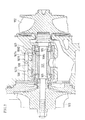
- FIG. 7 shows an example of a turbocharger including a bearing device of this type.
- a turbine blade 102 is rotatably and integrally disposed at one end portion of a turbine shaft 101.
- An impeller 103 of a compressor is rotatably and integrally disposed at the other end portion of the turbine shaft 101.
- a lubricant ejection hole (what is called an oil jet) 1085 that extends to an inner circumference of the bearing holder 107 is formed in the groove 1074, which is on the side of the turbine blade 102.
- the lubricant in the groove 1074 is ejected toward the ball bearing 105 on the right side of the figure, which is readily affected by heat from the side of turbine blade 102, so as to cool the ball bearing 105.
- the maximum gap in the radial direction of the foreign matter regulating gap is smaller than the minimum internal diameter of the oil hole.
- the downstream end of the oil supply path communicates with a one-sided region of the circular oil path including a gap in the radial direction that is larger than the gap in the radial direction of the foreign matter regulating gap. This ensures that the foreign matters contained in the oil supplied to the circular oil path inevitably pass through the foreign matter forming gap. Since there is a high possibility that the foreign matters that can pass through the foreign matter regulating gap pass through the oil hole, the possibility of the oil hole being blocked by the foreign matters contained in oil decreases.
- C 2 ⁇ D/2 denotes a flow path area of the lubricant passing between the oil film damper forming portion 77 and the bearing holder support surface 89.
- ⁇ d 2 /4 denotes a flow path area of the lubricant ejection note 76.
- C 1 ⁇ D/2 denotes a flow path area of the lubricant passing through the foreign matter regulating gap 91.
- the bearing support surface 89A of the bearing housing 8A includes the foreign matter collection portion 87, which communicates with the lowest position of the circular oil path formed between the first groove 54 of the semi-floating bearing 5A and the bearing support surface 89A (direct communication is implemented without the intermediation of the foreign matter regulating gap and the oil film damper forming, gap).
- the foreign matter collection portion 87 may be a through hole as shown in the figure, or may be the above-described foreign matter collection portion 87A having a recessed portion (see FIG. 3 ). Also, the foreign matter collection portion 87 or 87A may communicate with the circular oil path at a position different from its lowest position.
- the bearing device provide in the turbocharger according to this embodiment uses a full floating bearing 5B as a bearing portion to support the turbine shaft 1 in a bearing housing 8B.
- the lubricant supplied to the gap space 9C is also supplied to the third groove 55A, the fourth groove 55B, both end surfaces of the full floating bearing 5B, the turbine shaft I, and the like.
- Foreign matters than cannot pass through the foreign matter regulating gap 91A fall in the downward direction of the third groove 74 and are collected into the foreign matter collection portion 87.
- the foreign matters collected into the foreign matter collection portion 87 are discharged in the downward direction from the small diameter hole portion 872 of the foreign matter collection portion 87.
Landscapes
- Engineering & Computer Science (AREA)
- General Engineering & Computer Science (AREA)
- Mechanical Engineering (AREA)
- Chemical & Material Sciences (AREA)
- Oil, Petroleum & Natural Gas (AREA)
- Supercharger (AREA)
- Sliding-Contact Bearings (AREA)
- Rolling Contact Bearings (AREA)
Abstract
Description
- The present invention relates to a bearing device including a bearing portion to support a rotor shaft in a bearing housing. In particular, the present invention relates to a bearing device including an oil hole that penetrates the bearing portion from an outer circumference to an inner circumference of the bearing portion.
-
FIG. 7 shows an example of a turbocharger including a bearing device of this type. InFIG. 7 , aturbine blade 102 is rotatably and integrally disposed at one end portion of aturbine shaft 101. Animpeller 103 of a compressor is rotatably and integrally disposed at the other end portion of theturbine shaft 101. - The
turbine shaft 101 is supported in a freely rotatable manner by a bearing portion that includes abearing holder 107 andball bearings 105 in a bearinghousing 108. Theball bearings 105 are fitted in both end portions of thebearing holder 107. - The
bearing holder 107 has an approximately cylindrical shape and is fitted in the bearinghousing 8 with a predetermined gap maintained in the radial direction. Twogrooves outer circumference 1071 of thebearing holder 107. Circular oil paths are formed between thegrooves holder support surface 1081 in the bearinghousing 108. - A lubricant ejection hole (what is called an oil jet) 1085 that extends to an inner circumference of the
bearing holder 107 is formed in thegroove 1074, which is on the side of theturbine blade 102. The lubricant in thegroove 1074 is ejected toward the ball bearing 105 on the right side of the figure, which is readily affected by heat from the side ofturbine blade 102, so as to cool the ball bearing 105. -
Patent documents 1 to 3 disclose turbochargers each including a bearing device that includes the above-described lubricant ejection hole. - It is noted that patent document 4 fails to disclose the lubricant ejection hole, but discloses a technology such that a cylindrical space for foreign matter storage is disposed in the middle of a lubricant path, and foreign matters in the lubricant are removed through the foreign matter storage.
-
- Patent document 1: Japanese Unexamined Utility Model Application Publication No.
1990-72329 - Patent document 2: Japanese Unexamined Utility Model Application Publication No.
1994-1737A - Patent document 3: Japanese Unexamined Patent Application Publication No.
2008-504484 - Patent document 4: Japanese Unexamined Utility Model Application Publication No.
1993-14527 - Incidentally, the lubricant used to lubricate and cool the bearing portion oftentimes contains foreign matters, such as a burr and casting sand, associated with processing. In this case, there is a possibility that the foreign matters contained in the lubricant block an oil hole, such as the above-described lubricant ejection hole, that penetrates through the bearing portion from the outer circumference to the inner circumference of the bearing portion. When the lubricant ejection hole is blocked, it is possible that the temperature of the ball bearing increases, and an appropriate oil film cannot be maintained in the ball bearing.
- When the bearing portion is a floating bearing (a semi-floating bearing or a full floating bearing), the oil path penetrates through the floating bearing from the outer circumference to the inner circumference of the floating bearing, and thus servers as an oil path to supply lubricant supplied from the side of the bearing housing to the side of the turbine shaft. In this case, it is possible that when the oil path is blocked, an appropriate oil film between the turbine shaft and the floating bearing cannot be maintained.
- It is of course possible to reduce the possibility of the oil hole being blocked by foreign maters if a fine oil filter substantially dedicated to the turbocharger is used. However, in this case, other problems occur in that the piece-part count increases, and the size of the device incorporating the oil filter increases.
- The present invention has been achieved in view of the above circumstances, and it is an object of the present invention to provide a bearing device that decreases, without providing additional components such as an oil filter, the possibility that an oil hole penetrating through a bearing portion from an outer circumference to an inner circumference of the bearing, portion is blocked by foreign matters contained in oil.
- In order to salve the above-described problems, a bearing device of the present invention is configured as follows.
- A bearing device according to the present invention includes a bearing portion, a circular oil path, and an oil hole. The bearing portion supports a rotor shaft in a bearing housing. The circular oil path is formed in a circumferential direction between the bearing housing and the bearing portions. The oil hole penetrates through the bearing portion from an outer circumference to an inner circumference of the bearing portion so as to receive a supply of oil from the circular oil path. A foreign matter regulating gap including a gap between the bearing portion and the bearing housing is formed between the circular oil path and the oil hole. A maximum value of a gap of a radial direction of the foreign matter regulating gap is smaller than a minimum value of an internal diameter of the oil hole.
- With the bearing device thus configured, since the maximum gap in the radial direction of the foreign matter regulating gap is smaller than the minimum internal diameter of the oil hole, there is a high possibility that foreign matters that can pass through the foreign matter regulating gap pass through the oil hole. This reduces the possibility of oil hole being blocked by the foreign matters contained in oil.
- The bearing portion may support the rotor shaft in the bearing housing with an oil film damper formed between the bearing portion and the bearing housing.
- With the bearing device thus configured, the possibility of the oil hole being blocked by the foreign matters contained in oil reduces without providing an additional oil filter substantially dedicated to the bearing device. This ensures the necessary amount and pressure of oil to form the oil film damper without concern over reductions in the amount and pressure of the supplied oil caused by the mounting of the oil filter.
- Preferably, in the bearing device above, a sum of a flow path area of the oil hole and a flow path area of an oil film damper forming gap that forms the oil film damper in a downstream side of the foreign matter regulating gap is smaller than a flow path area of the foreign matter regulating gap.
- With the bearing device thus configured, the necessary oil amount of oil to be discharged from the oil hole and the necessary oil amount of oil to be supplied to the oil film damper forming gap are readily obtained without increasing the amount and pressure of oil to be supplied to the bearing device.
- For example, the bearing portion may be fitted in the bearing housing, and may include a bearing holder configured to form an film damper between the bearing holder and the bearing portion and may include a ball bearing supporting the rotor shaft in the bearing holder. The circular oil path may be formed between the bearing housing and bearing holder in the circumferential direction. The oil hole may include an oil ejection hole penetrating through the bearing holder from an outer circumference to an inner circumference of the bearing holder so as to receive a supply of oil from the circular oil path through the foreign matter regulating gap and so as to eject the oil toward the ball bearing or to a vicinity of the ball bearing.
- For example, bearing portion may include a semi-floating bearing axially non-rotatably fitted in the bearing housing.
- For example, the bearing portion may include a full floating bearing axially rotatably fitted in the bearing housing.
- The bearing device of the present invention may be alternatively configured as follows.
- Another bearing device according to the present invention includes a bearing portion, an oil supply path, and an oil hole. The bearing portion supports a rotor shaft in a bearing housing. The bearing portion includes a groove formed on an outer circumference of the bearing portion in a circumferential direction. The supply path is disposed in the bearing housing and communicates with a circular oil path formed between the bearing housing and the groove of bearing portion in the circumferential direction. The oil hole penetrates through the bearing portion from the groove of the bearing portion to an inner circumference of the bearing portion so as to receive a supply of oil from the circular oil path. The groove may include a tapered bottom surface inclined relative to an axis of the rotor shaft. A foreign matter regulating gap is formed including a gap between the bearing housing and an outer circumferential line that passes in the circumferential direction through a portion of an inlet outline of the oil hole closest to the axis of the rotor shaft. A maximum value of a gap of a radial direction of the foreign matter regulating gap is smaller than a minimum value of an internal diameter of the oil hose. A downstream end of the oil supply path communicates with a one-sided region of a circular oil path including a gap in the radial direction larger than the gap in the radial direction of the foreign matter regulating gap.
- With the bearing device thus configured, the maximum gap in the radial direction of the foreign matter regulating gap is smaller than the minimum internal diameter of the oil hole. The downstream end of the oil supply path communicates with a one-sided region of the circular oil path including a gap in the radial direction that is larger than the gap in the radial direction of the foreign matter regulating gap. This ensures that the foreign matters contained in the oil supplied to the circular oil path inevitably pass through the foreign matter forming gap. Since there is a high possibility that the foreign matters that can pass through the foreign matter regulating gap pass through the oil hole, the possibility of the oil hole being blocked by the foreign matters contained in oil decreases.
- The bearing portion may support the rotor shaft in the bearing housing with an oil film damper formed between the bearing portion and the bearing housing.
- With the bearing device thus configured, the possibility of the oil hole being blocked by the foreign matters contained in oil reduces without providing an additional oil filter substantially dedicated to the bearing device. This ensures the necessary amount and pressure of oil to form the oil film damper without concern over reductions in the amount and pressure of the supplied oil caused by the mounting of the oil filler.
- For example, the bearing portion may be fitted in the bearing housing, and may include a bearing holder configured to form the oil film damper between the bearing holder and the bearing portion and may include a ball bearing supporting the rotor shaft in the bearing holder. The groove of the bearing portion may be formed on the outer circumference of the bearing holder in the circumferential direction. The circular oil path may bye formed between the bearing housing and the groove of the bearing holder in the circumferential direction. The oil hole may include an oil ejection hole penetrating through the bearing holder from a bottom surface of the groove of the bearing holder to an inner circumference of the bearing holder so as to receive a supply of oil from the circular oil path through the foreign matter regulating gap and so as to eject the oil toward the ball bearing or to a vicinity of the ball bearing.
- Preferable, a through hole is formed in the bearing housing. The through hole may communicate with the circular oil path so as to collect foreign matters in the circular oil path.
- With the bearing device thus configured, the foreign matters in the oil that cannot pass through the foreign matter regulating gap are collected into the through hole through the circular oil path and discharged from the bearing housing. This reduces the possibility that the foreign matters are left in the circular oil path and become engaged with the foreign matter regulating gap.
- Preferable, a recessed portion is formed in the bearing housing. The recessed portion may communicate with the circular oil path so as to collect foreign matters in the circular oil path.
- With the bearing device thus configured, the foreign matters in the oil that cannot pass through the foreign matter regulating gap are collected into the recesses portion through the circular oil path. This reduces the possibility that the foreign matters are left in the circular oil and become engaged with the foreign matter regulating gap. Employing a recessed portion instead of a through hole to collect the foreign matter minimizes the reduction in oil pressure in the circular oil path. This ensures that the oil pressure in the oil film damper forming gap is readily maintained, and this facilitates formation of a preferable oil film damper.
- Preferably, a through hole is formed in the bearing housing. The through hole may communicate with a lowest position of the circular oil path so as to collect foreign matters in the circular oil path.
- With the bearing device thus configured, the foreign matters in the oil that cannot pass through the foreign matter regulating gap, in particular, foreign matters that easily precipitate in the oil, fall down to the lowest position of the circular oil path, and are collected into the through hole and discharged from the bearing housing. This further reduces the possibility that the foreign matters are left in the circular oil path and become engaged with the foreign matter regulating gap.
- Preferably, a recessed portion is formed in the bearing housing. The recessed portion may communicate with a lowest position of the circular oil path so as to collect foreign matters in the circular oil path.
- With the bearing device thus configured, the foreign matters in the oil that cannot pass through the foreign matter regulating gap, in particular, foreign matters that easily precipitate in the oil, fall down to the lowest position of the circular oil path and are collected into the recessed portion. This further reduces the possibility that the foreign matters are left in the circular oil path and become engaged with the foreign matter regulating gap. Employing a recessed portion instead of a through hole to collect the foreign matters minimizes the reduction in oil pressure in the circular oil path. This ensures that the oil pressure in the oil film damper forming gap is readily maintained, and this facilitates formation of a preferable oil film damper.
- The present invention reduces, without providing additional components such as an oil filter, the possibility that the oil hole penetrating through the bearing portion from the outer circumference to the inner circumference of the bearing portion is blocked by foreign matters contained in oil.
-
- [
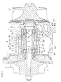
FIG. 1] FIG. 1 is a cross-sectional view of a main part of a turbocharger that includes a bearing device according to a first embodiment of the present invention. - [
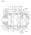
FIG. 2] FIG. 2 is a cross-sectional view of the bearing device according to the first embodiment of the present invention. However, a bearing holder is not shown in the cross-sectional view. - [
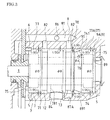
FIG. 3] FIG. 3 is another cross-sectional view of the bearing device according to the first embodiment of the invention. However, the bearing holder is not shown in the cross-sectional view.FIG. 3 is also used to describe a modification of a foreign matter collection portion. - [
FIG. 4] FIG. 4 is a cross-sectional view of a main part of a turbocharger that includes a bearing device according to a second embodiment of the present invention. - [
FIG. 5] FIG. 5 is a cross-sectional view of a main part of a turbocharger that includes a bearing device according to a third embodiment of the present invention. - [
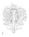
FIG. 6] FIG. 6 is a cross-sectional view of a main part of a turbocharger that includes a bearing device according to a fourth embodiment of the present invention. - [
FIG. 7] FIG. 7 is a cross-sectional view of a main part of a turbocharger that includes a bearing device according to a conventional example. - A first embodiment of the present invention will be described.
-
FIG. 1 shows a cross-sectional view of a turbocharged that includes a bearing device of the present invention.FIG. 2 shows an enlarged view of a main part ofFIG. 1 . - As shown in
FIG. 1 , aturbine blade 2 is rotatably and integrally disposed at once end portion of a turbine shaft 1 (rotor shaft), and animpeller 3 of a compressor is rotatably and integrally disposed at the other end portion of theturbine shaft 1. Theturbine blade 2 is disposed at an exhaust gas flow path in a turbine housing and rotated by the exhaust gas flowing in the exhaust gas flow path. Theimpeller 3 is disposed at a fresh air path in a compressor housing (not shown). Theimpeller 3 is rotated by the rotational torque of theturbine blade 2 transmitted via theturbine shaft 1, so as to send fresh air to an intake surge tank, which is not shown, while adding pressure on the fresh air. - In the bearing
housing 8, theturbine shaft 1 is rotatably supported by a bearing portion that includes abearing holder 7 and a pair ofball bearings 5. - The
ball bearings 5 are each a radial bearing to support load acting orthogonal to the rotating shaft, and are fitted in both end portions of thebearing holder 7, described later. It is noted thatreference numeral 11 denotes asleeve 11 that is fitted onto the outer circumference of the turbine shaft I betweeninner rings 51 of theball bearings 5. Thesleeve 11 is disposed to maintain the distance between theinner rings 51 of theball bearings 5. - The
bearing holder 7 has an approximately cylindrical shape and is non-rotatably fitted in the bearinghousing 8. That is, thebearing holder 7 is secured to the bearinghousing 8 with apin 6 to prohibit rotation about the axis of the cylindrical shape. However, a predetermined gap is secured between the bearingholder 7 and the bearinghousing 8 to form an oil film damper, which allows thebearing holder 7 to travel in the radial direction within the range of this gap. - As shown in
FIG. 2 , can anouter circumference 71 of thebearing holder 7, afirst groove 72, asecond groove 73, and athird groove 74 are formed in parallel to each other at intervals in the circumferential direction. Circular oil paths are formed between thegrooves 72 to 74 and a cylindrical bearingholder support surface 89 formed in the bearinghousing 8. - The circular oil paths formed between the
first groove 72 and the bearingholder support surface 89 and between thesecond groove 73 and the bearingholder support surface 89 communicate with divergingpaths 82 of alubricant supply passage 81, described later. A lubricant is supplied from the divergingpaths 82. The lubricant supplied to thefirst groove 72 and thesecond groove 73 flows to both axial directions of theturbine shaft 1, and is supplied to an approximatelycircular gap space 9 formed between theouter circumference 7 of thebearing holder 7 and the bearingholder support surface 89 of the bearinghousing 8. The lubricant supplied to thegap space 9 forms an oil film damper to attenuate vibrations between the bearingholder 7 and the bearinghousing 8. - The lubricant supplied to both axial directions of the turbine shaft I from the
first groove 72 and thesecond groove 73 is also supplied to thethird groove 74, gaps (not shown) between end surfaces 75 of thebearing holder 7 and walls opposite the end surfaces 75,ball bearings 5, theturbine shaft 1, and the like. - The
third groove 74, among thegrooves 72 to 74, is closest to the side of theturbine blade 2. A lubricant ejection hole (what is called an oil jet) 76 extends from thethird groove 74 to aninner circumference 79 of thebearing holder 7. - The
lubricant ejection hole 76 ejects a lubricant toward theball bearing 5 or to the vicinity of theball bearing 5, and is disposed to cool theball bearing 5. It is noted that thelubricant ejection hole 76 shown inFIG. 1 is a two-stage hole having different and small diameters such that the diameter on the inner circumference side of theholder 7 is small. -
Reference numeral 781 denotes an outlet for the lubricant and is formed at a lower portion of the bearing holder two to communicate with theinner circumference 79 and theouter circumference 71 of thebearing holder 7. Theoutlet 781 is disposed to downwardly discharge the lubricant flowing into thebearing holder 7. - The bearing
housing 8 is coupled between the turbine housing and the compressor housing. Thelubricant supply passage 81 is an oil path to supply the lubricant and formed in the bearinghousing 8. Thelubricant supply passage 81 diverges in two on its downstream side and communicates with the circular oil paths formed between the bearing,holder support surface 89 and thefirst groove 72 and thesecond groove 73 of the bearing holder 7 (direct communication is implemented, without the intermediation of a foreign matter regulating gap and an oil film damper forming gap, which will be described later). - On the bearing
holder support surface 89 of thebearing holder 8, a foreignmatter collection portion 87 is disposed. The foreignmatter collection portion 87 communicates with the lowest position of the circular oil path formed between thesecond groove 73 of thebearing holder 7 and the bearingholder support surface 89. It is noted that the foreignmatter collection portion 87 directly communicates with the circular oil path without the intermediation of the foreign matter regulating gap and the oil film damper forming gap, which will be described later. The foreignmatter collection portion 87 is disposed to collect foreign matters precipitated from thesecond groove 73 of thebearing holder 7. The foreignmatter collection portion 87 exemplified in the drawings is formed at the lowest position of the bearingholder support surface 89 of thebearing holder 8, and the foreignmatter collection portion 87 is a through hole that penetrates through aperiphery wall 891 of the bearinghousing 8. The foreignmatter collection portion 87 includes a largediameter hole portion 871 and a smalldiameter hole portion 872. The smalldiameter hole portion 872 has a diameter smaller than that of the largediameter hole portion 871 and is continuously disposed at a lower portion of the largediameter hole portion 871. Preferably, the largediameter hole portion 871 includes an internal diameter equal to or slightly larger than the groove width of thesecond groove 73. It is preferred, however, that the largediameter hole portion 871 not communicate with theoutlet 781 and thethird groove 74. Regarding the size of the smalldiameter hole portion 872, it is preferred that its opening area is as small as possible to form a preferable oil film damper. It is noted that the foreignmatter collection portion 87 may communicate with the circular oil path at a position different from its lowest position. -
Reference numeral 84 denotes an outlet for the lubricant and is formed at the lowest position of theperiphery wall 891 of the bearinghousing 8. Theoutlet 84 is continuous from theoutlet 781. Theoutlet 84 is also disposed to downwardly discharge the lubricant flowing into thebearing holder 7. -
Reference numeral 88 denotes an oil discharge outlet of the turbocharger. Lubricants flowing from theoutlets oil discharge outlet 88 to the downward direction of the turbocharger. - Next, the dimensions of the
bearing holder 7 will be described by referring toFIG. 2 . On theouter circumference 71 or thebearing holder 7, oil filmdamper forming portions 77, the above-described first, tothird grooves 72 to 74, and a foreign matter regulating-gap forming portion 70, described later, are formed. The oil filmdamper forming portions 77 each have a diameter φ D, which is set to ensure a gap (hereinafter referred also to as an "oil film damper forming gap") in which to form the oil film damper between theouter circumference 71 and the bearingholder support surface 89 of thebearing holder 8. - One of the oil film
damper forming portions 77 is formed on the side of the impeller relative to thefirst groove 72. Another oil filmdamper forming portion 77 is formed between thefirst groove 72 and thesecond groove 73. The other oil filmdamper forming portions 77 is formed on the side of theturbine blade 2 relative to thethird groove 74. The diameter φ D of each oil filmdamper forming portion 77 is set to ensure a maximum gap C2 in the radial direction with respect to the bearing holder support surfaces 89 of the bearing holder 8 (the maximum gap C2 is a difference between the internal diameter of the bearingholder support surface 89 and the external diameter of the oil film damper forming portion 77). For example, the maximum gap C2 in the radial direction may be set at approximately 0.1 mm. - The foreign matter regulating-
gap forming portion 70 is formed between thesecond groove 73 and thethird groove 74 of theouter circumference 71 of thebearing holder 7. In the gap between the foreign matter regulating-gap forming portion 70 and the bearingholder support surface 89 of thebearing holder 8, a foreignmatter regulating gap 91 is formed to block passing of a foreign matter of a size that is equal to or larger than a predetermined size. The maximum gap in the radial direction of the foreignmatter regulating gap 91 is denoted C1. - Incidentally, the above-described dimensions C1, C2, and D, and a minimum internal diameter d of the
lubricant ejection hole 76 satisfy the followingformula 1. -

Based on theformula 1, aformula 2 is obtained as follows.
Multiplying both sides of theformula 2 by πD/2 results in the following.
- C2πD/2 denotes a flow path area of the lubricant passing between the oil film
damper forming portion 77 and the bearingholder support surface 89. πd2/4 denotes a flow path area of thelubricant ejection note 76. C1πD/2 denotes a flow path area of the lubricant passing through the foreignmatter regulating gap 91. - An internal diameter φ Z of the small
diameter hole portion 872 of the foreignmatter collection portion 87 satisfies the following formula 4. -

formulas 1 to 4 include C1 = 0.2 mm, C2 = 0.1 mm, d = 0.6, D = 21 , Z = 1.5. - If a turbocharger including the
bearing holder 7 and bearinghousing 8 with their dimensions set in the above-described manner, when a lubricant is supplied by discharge from anoil supply hole 86 under a pressure that is equal to or higher than a predetermined level (a pressure that is equal to or higher than the necessary pressure to form the oil film damper), the lubricant is first supplied to thefirst groove 72 and thesecond groove 73 through thelubricant supply passage 81 and the divergingpaths 82. Then, the lubricant is supplied to thethird groove 74, thegap space 9, and the like via thefirst groove 72 and thesecond groove 73. This causes the oil film damper to be formed and the lubricant to be ejected from thelubricant ejection hole 76. - In this case, the relation of the maximum gap C1 in the radial direction of the foreign
matter regulating gap 91 and the minimum internal diameter d of thelubricant ejection hole 76 is represented as follows based on theformula 1.
Accordingly, there is a high possibility that the foreign matters passable through the foreignmatter regulating gap 91 pass through thelubricant ejection hole 76. This reduces the possibility of thelubricant ejection hole 76 being blocked by the foreign matters in the lubricant. - Foreign matters that cannot pass through the foreign
matter regulating gap 91 fall in the downward direction of thesecond groove 73 and are collected into the foreignmatter collection portion 87. Further, the foreign matters collected into the foreignmatter collection portion 87 are further discharged into the downward direction through the smalldiameter hole portion 872 of the foreignmatter collection portion 87. This prevents the foreign matters form accumulating at the lower portion of thesecond groove 73. This, in turn, reduces the possibility that the foreign matters are left in thesecond groove 73 and become engaged with the foreignmatter regulating gap 91. - The lubricant supplied to the
lubricant ejection hole 76 and to agap space 9A, which is in the downstream side relative two the inlet of thelubricant ejection hole 76, is supplied through the foreignmatter regulating gap 91. In this respect, as theformula 3 shows, the sum of the flow path area of thelubricant ejection hole 76 and the flow path area of thegap space 9A (oil film damper forming gap) is smaller than the flow path area of the foreignmatter regulating gap 91. This eliminates the need for increasing the amount and pressure of the lubricant to be supplied, and ensures that the amount of the lubricant ejected from thelubricant ejection hole 76 is on the same lever was the level associated with a turbocharger according to a conventional example (seeFIG. 7 ). Also, a sufficient amount of oil is supplied to thegap space 9A, which is in the downstream side relative, to thethird groove 74, where thelubricant ejection hole 76 is disposed. Thus, a preferable oil film damper is formed in thegap space 9A. - The bearing device according to this embodiment reduces, without providing a fine oil filter substantially dedicated to the turbocharger, the possibility of the lubricant ejection hole being, blocked by foreign matters. Specifically, providing additional components such as a fine oil filter involves problems such as enlargement of the turbocharger, an increase in the piece-part count, and a reduction in oil pressure of the oil film damper. The bearing device according to this embodiment eliminates these problems and reduces the possibility of the lubricant ejection hole being blocked by foreign matters.
- With the bearing device according to this embodiment, the foreign
matter regulating gap 91 is disposed at a position close to the lubricant ejection hole 76 (within the range of the entire length of the bearing holder 7). This prevents foreign matters such as chips from entering thelubricant ejection hole 76 when the foreign matters occur at a place relatively close to thelubricant hole 76 soch as in thelubricant supply passage 81 in the bearinghousing 8. - The bearing device according to this embodiment reduces the possibility of the lubricant ejection hole being blocked by foreign matters without enlarging the diameter of the lubricant ejection hole. Specifically, when the diameter of the lubricant ejection hole is enlarged, it is necessary to enhance the abilities (the amount and pressure of oil to be supplied) of the oil supply device (oil pump) on the upstream side, in order to maintain the force of the lubricant ejected from the lubricant ejection hole. This, however, increases the amount of oil at the bearing portion and increases the agitation resistance of oil. This, as a result, can degrade the driving response of the turbocharger. Additionally, enhancing the abilities of the oil supply device on the upstream side can cause an oil leakage to the fresh air flow path and the exhaust gas flow path. The bearing device according to this embodiment reduces the possibility of the lubricant ejection hole being blocked by foreign matters without enhancing the abilities of the oil supply device. This eliminates the above-described problems associated with the enhancement of the abilities of the oil supply device.
- The foreign
matter collection portion 87 penetrates through theperiphery wall 891 of the bearinghousing 8, thus providing communication between the interior of thesecond groove 73 and awaste oil space 80, which is a pressure release region (region close to atmospheric pressure). Accordingly, it is possible that the pressure in thesecond groove 73 decreases and a preferable oil film damper cannot be maintained. In order to maintain the oil pressure in thesecond groove 73 and the oil film damper forming gap, it is necessary to enhance the abilities (the amount and pressure of oil to be supplied) of the oil supply device (oil pump) on the upstream side. - However, as shown in
FIG. 3 , the pressure in thesecond groove 73 can be maintained with the use of a foreignmatter collection portion 87A, which is a bottomed recessed portion that not directly communicate with the pressure release region. It is noted that the foreignmatter collection portion 87A is also disposed at a position to communicate with the lowest position of the circular oil path formed between thesecond groove 73 and the bearingholder support surface 89 in the bearing housing 8 (direct communication is implemented without the intermediation of the foreign matter regulating gap and the oil film damper forming and is disposed at the lowest position of the bearingholder support surface 89 of the bearinghousing 8. Preferably, the foreignmatter collection portion 87A also not communicate, with theoutlet 781 and thethird groove 74. It is noted that the foreignmatter collection portion 87A may with the oil path at a position different from its lowest position. - Next, a second embodiment of the present invention will be described by referring to
FIG. 4 . It is noted that like reference numerals designate corresponding or identical elements throughout the first and second embodiments, and these elements will not be described here. - The bearing device provided in the turbocharger according to this embodiment uses a
semi-floating bearing 5A as a bearing portion to support the turbine shaft I in a bearing housing 8A. - The
semi-floating bearing 5A has an approximately cylindrical shape and is non-rotatably fitted in the bearing housing 8A. That is, the semi-floating bearing 5A is secured to the bearing housing 8A with thepin 6 to prohibit rotation about the axis of the cylindrical shape. However, a predetermined gap is secured between thesemi-fioating bearing 5A and the bearing housing 8A to form an oil film damper between thesemi-floating bearing 5A and the bearing housing, 8A, which allows the semi-floating bearing 5A to travel in the radial direction within the range of this gap. - On an
outer circumference 53 of thesemi-floating bearing 5A, afirst groove 54 and asecond groove 55 are formed in the circumferential direction at intervals. Circular oil paths are formed between thegrooves bearing support surface 89A in the hearing housing 8A. The circular oil paths communicate with thelubricant supply passage 81 disposed in the bearing housing 8A (direct communication is implemented without the intermediation of the foreign matter regulating gap and the oil film damper forming gap), so as to receive a supply of lubricant directly from thelubricant supply passage 81. The lubricant supplied to thefirst groove 54 is flows to both axial directions of theturbine shaft 1, and is supplied to an approximately circular gap space 98 formed between theouter circumference 53 of the semi-floating bearing 5A and the bearingsupport surface 89A of the bearing housing 8A. The lubricant supplied to thegap space 9B forms an oil film damper to attenuate vibrations between thesemi-floating bearing 5A the bearing housing 8A. - The lubricant supplied to the
gap space 9B is also supplied to thesecond groove 55, gaps (not shown) between end surfaces of the semi-floating bearing 5A and walls opposite the end surfaces, theturbine shaft 1, and the like. - The
second groove 55 is disposed on the side of theturbine blade 2 relative, to thefirst groove 54. Anoil hole 58 is formed to communicate thesecond groove 55 with aninner circumference 57 of thesemi-floating bearing 5A. Theoil hole 58 functions as an oil path through which the lubricant supplied to thesecond groove 55 is supplied to theinner circumference 57 of thesemi-floating bearing 5A. The lubricant supplied to theinner circumference 57 of thesemi-floating bearing 5A is supplied between theinner circumference 57 of the semi-floating bearing 5A and theturbine shaft 1 so as to form an oil film damper and a lubricant film. - On the
outer circumference 53 of thesemi-floating bearing 5A, oil filmdamper forming portions 59, the above-describedgrooves gap forming portion 50 are formed. The oil filmdamper forming portions 59 each have a diameter set to ensure a gap (hereinafter also referred to as an "oil film damper forming gap") in which to form the oil film damper between theouter circumference 53 and the bearingsupport surface 89A of the bearing housing 8A. One of the oil filmdamper forming portions 59 is formed on the side of theimpeller 3 relative to thefirst groove 54, while another oil filmdamper forming portion 59 is formed on the side of theturbine blade 2 relative to thethird groove 55. - The foreign matter regulating-
gap forming portion 50 is formed between thefirst groove 54 and thesecond groove 55. In the gap between the foreign matter regulating-gap forming portion 50 and the bearingsupport surface 89A of the bearing housing 8A , a foreignmatter regulating gap 91 is formed to block passing of a foreign matter of a size that is equal to or larger than a predetermined size. - Similarly to the first embodiment, the bearing
support surface 89A of the bearing housing 8A according to the second embodiment includes the foreignmatter collection portion 87, which communicates with the lowest position of the circular oil path formed between thefirst groove 54 of the semi-floating bearing 5A and the bearingsupport surface 89A (direct communication is implemented without the intermediation of the foreign matter regulating gap and the oil film damper forming, gap). The foreignmatter collection portion 87 may be a through hole as shown in the figure, or may be the above-described foreignmatter collection portion 87A having a recessed portion (seeFIG. 3 ). Also, the foreignmatter collection portion - In this embodiment, similarly to the first embodiment, the dimensions of the portions of the semi-floating bearing 5A are set. Specifically, the maximum gap in the radial direction of the foreign
matter regulating gap 91 is smaller than the minimum internal diameter of theoil hole 58. This reduces the possibility of theoil hole 58 being blocked by foreign matters in the lubricant. - The sum of the flow path area of the
oil hole 58 and the flow path area of thegap space 9B, which is in the downstream side relative to the inlet of the oil hole 58 (which is the gap space between the bearingsupport surface 89A and the outer circumference of thesemi-floating bearing 5A), is smaller than the flow path area of the foreignmatter regulating gap 91. This eliminates the need for increasing the amount and pressure of the lubricant to be supplied, and ensures a sufficient amount of oil to be supplied to the side of the turbine shaft I through theoil hole 58. Also, a sufficient amount of oil is supplied to thegap space 9B, which is in the downstream side relative to thesecond groove 55, where theoil hole 58 is disposed. Thus, a preferable oil film damper is formed in thegap space 9B. - Next, a third embodiment will be described by referring to
FIG. 5 . It is noted that like reference numerals designate corresponding or identical elements throughout the first to third embodiments, and these elements will not be described here. - The bearing device provide in the turbocharger according to this embodiment uses a full floating
bearing 5B as a bearing portion to support theturbine shaft 1 in a bearinghousing 8B. - The full floating bearing 5B has an approximately cylindrical shape and is rotatably fitted in the bearing
housing 8B. A predetermined gap is secured between the full floatingbearing 5B and the bearinghousing 8B to form the oil film damper and the lubricant film, which allows the semi-floating bearing 5B to travel in the radial direction within the range of this gap. -
Reference numeral 92 denotes a thrust bearing to receive the thrust force of the turbine shaft while rotating.Reference numeral 93 denotes a ring member that is rotatable and integrally fitted onto the turbine shaft I and engaged with the thrust bearing 92 in the axial direction.Reference numeral 94 denotes a regulating member secured in the bearinghousing 8B. The full floatingbearing 5B is hallowed restricted movement in the axial direction within a predetermined range by thering member 93 and the regulatingmember 94. - On an
outer circumference 53A of the full floating bearing 5B, afirst groove 54A, asecond groove 54B, athird groove 55A, and afourth groove 55B are formed in the circumferential direction at intervals. Circular oil paths are formed between thegrooves bearing support surface 89B in the bearinghousing 88. The circular oil paths formed between thefirst groove 54A and the bearingholder support surface 89B and between thesecond groove 54B and the bearingsupport surface 89B communicate with the divergingpaths 82 of the lubricant supply passage 81 (direct communication is implemented without the intermediation of the foreign matter regulating gap and the oil film damper forming gap), so as to receive a supply of lubricant directly from the divergingpaths 82. The lubricant supplied to thefirst groove 54A and thesecond groove 54B flows to both axial directions of theturbine shaft 1 and is supplied between theouter circumference 53A of the full floatingbearing 5B and the bearing support surfaces 89B. The lubricant supplied to agap space 9C forms the oil film damper two attenuate vibration between the full floatingbearing 5B and the bearinghousing 8B. - The lubricant supplied to the
gap space 9C is also supplied to thethird groove 55A, thefourth groove 55B, both end surfaces of the full floatingbearing 5B, the turbine shaft I, and the like. - The
third groove 55A and thefourth groove 55B are respectively disposed at axially external sides of thefirst groove 54A and thesecond groove 54B. Oil holes 58A respectively penetrate from thethird groove 55A and thefourth groove 55B (theouter circumference 53A of the full floatingbearing 5B) to aninner circumference 57A of the full floatingbearing 5B. - The oil holes 58A each function as an oil path through which the lubricant supplied to the
third groove 55A or thefourth groove 55B is supplied to theinner circumference 57A of the full floatingbearing 5B. The lubricant supplied to theinner circumference 57A of the full floatingbearing 5B is supplied between theinner circumference 57A of the full floatingbearing 5B and the turbine shaft I so as to form the oil film damper and the lubricant film. - On the
outer circumference 53A of the full floatingbearing 5B, oil filmdamper forming portions 59A, thegrooves gap forming portions 50A are formed. The oil filmdamper forming portions 59A each have a diameter set to ensure a gap (hereinafter also referred to as an "oil film damper forming gap") in which two form the oil film damper between theouter circumference 53A and the bearingsupport surface 89B or the bearinghousing 8B. One of the oil filmdamper forming portions 59A is formed of the side of theimpeller 3 relative to thethird groove 55A. Another oil filmdamper forming portion 59A is formed on the side of theturbine blade 2 relative to thefourth groove 55B. The other oil filmdamper forming portion 59A is formed between thefirst groove 54A and thesecond groove 54B. - One of the foreign matter regulating-
gap forming portions 50A is formed between thefirst groove 54A and thethird groove 55A. Another foreign matter regulating-gap forming portion 50A is formed between thesecond groove 54B and thefourth groove 55B. In the gap between each foreign matter regulating-gap forming portion 50A and the bearing support surfaces 89B, a foreignmatter regulating gap 91 is formed to block passing of a foreign matter of a size that is equal to or larger than a predetermined size. - Similarly to the first embodiment, the bearing
support surface 89B of the bearinghousing 8B according to the third embodiment includes the foreignmatter collection portions 87, which communicate with the lowest positions of the circular oil paths formed between thefirst groove 54A of the full floatingbearing 5B and the bearingsupport surface 89B and between thesecond groove 54B of the full floatingbearing 5B and the bearingsupport surface 89B (direct communication is implemented without the intermediation of the foreign matter regulating gap and the oil film damper forming gap). The foreignmatter collection portions 87 each may be a through hole as shown in the figure, or may be the above-described foreignmatter collection portion 87A having a recessed portion (seeFIG. 3 ). Also, the foreignmatter collection portion - In this embodiment, similarly to the first embodiment, the dimensions of the portions of the full floating
bearing 5B are set. Specifically, the maximum gap in the radial direction of the foreignmatter regulating gap 91 is smaller than the minimum internal diameter of theoil hole 58A. This reduces the possibility of theoil hole 58A being blocked by foreign matters in the lubricant. - The sum or the flow path area of the
oil hole 58A and the flow path area of thegap space 9C, which is in the downstream side relative to the inlet of theoil hole 58A (which its the gap space between the bearingsupport surface 89B and the outer circumference of the full floatingbearing 5B), is smaller than the flow path area of the foreignmatter regulating gap 91. This eliminates the need for increasing the amount and pressure of the lubricant to be supplied, and ensures a sufficient amount of oil to be supplied to the side of theturbine shaft 1 through theoil hole 58A. Also, a sufficient amount of oil is supplied to thegap space 9C, which is in the downstream side relative to thethird groove 55A and thefourth groove 55B, where theoil holes 58A are disposed.
Thus, a preferable oil film damper is formed in thegap space 9C. - Next, a fourth embodiment of the present invention will be described by referring to
FIG. 6 . It is noted that like reference numerals designate corresponding or identical elements throughout the first to fourth embodiments, and these elements will not be described here. - The bearing device provided in the turbocharger according to this embodiment eliminated the
second groove 55, which is employed in thebearing holder 7 of the first embodiment. The divergingpath 82 of thelubricant supply passage 81 communicate with the circular oil path formed between thethird groove 74 and the bearing, holder support surface 89 (direct communication is implemented without the intermediation of the oil film damper forming gap). - The
third groove 74 includes a tapered bottom surfaces 74b inclined relative to the axis of theturbine shaft 1. In this embodiment, the bottom surface 74b is decremental in the direction from the side of theturbine blade 2 to the side of theimpeller 3 along the axis of theturbine shaft 1. - In this embodiment, a foreign
matter regulating gap 91A is formed to block passing of a foreign matter of a size that is equal to or larger than a predetermined size. The foreignmatter regulating gap 91A is formed in the gap in the radial direction between the bearingholder support surface 89 and an outer circumferential line L1 that passes in the circumferential direction through a portion 761 of the inlet outline of thelubricant ejection hole 76 closest to the axis of therotor 1. - Assume that C3 is a difference in radius between the oil film
damper forming portion 77 and the circular outer circumferential line L1. Then, the maximum gap in the radial direction of the foreignmatter regulating gap 91A is represented as C2 + C3, C2 + C3 satisfies the followingformula 6. -

matter regulating gap 91 A is lower than the minimum internal diameter d of thelubricant ejection hole 76. - The downstream end of the diverging
path 82 of thelubricant supply passage 81 communicates with the circular oil path formed between the third groove and the bearingholder support surface 89 in a region S, described inter. The region S is a one-sided region of the circular oil path that is a gap in the radial direction targer than the gap in the radial direction of the foreignmatter regulating gap 91A. In this embodiment, the region S is on the side of thecompressor 3 in the axial direction relative, to the foreignmatter regulating gap 91A. - Similarly to the first embodiment, the foreign
matter collection portion 87 is provided on the bearingholder support surface 89. The foreignmatter collection portion 87 communicates with the lowest position of the circular oil path formed between thethird groove 74 and the bearing holder support surfaces 89 (direct communication is implemented without the intermediation of the oil film damper forming gap). The foreignmatter collection portion 87 may be a through hole as shown in the figure, or may be the above-described foreignmatter collection portion 87A having a recessed portion (seeFIG. 3 ). Also, the foreignmatter collection portion - In a turbocharger including the
bearing holder 7 thus configured, when a lubricant is supplied, by discharge from anoil supply hole 86 under a pressure that is equal to or higher than a predetermined level (a pressure that is equal to or higher than the necessary pressure to form the oil film damper), the lubricant is supplied to thefirst groove 72 and thethird groove 74 through thelubricant supply passage 81 and the divergingpaths 82. Then, the lubricant is supplied to thegap space 9 and the like via thefirst groove 72 and thethird groove 74. This causes the oil film damper to be formed. The lubricant in thethird groove 74 is ejected toward theball bearing 5 from thelubricant ejection hole 76. - In this case, the
formula 6 shows that the maximum gap C2 + C3 in the radial direction of the foreignmatter regulating gap 91A is lower than the minimum internal diameter d of thelubricant ejection hole 76. Accordingly, there is a high possibility that the foreign matters passable through the foreignmatter regulating gap 91A pass through thelubricant ejection hole 76. This reduces the possibility of thelubricant ejection hole 76 being blocked by the foreign matters in the lubricant. - Foreign matters than cannot pass through the foreign
matter regulating gap 91A fall in the downward direction of thethird groove 74 and are collected into the foreignmatter collection portion 87. The foreign matters collected into the foreignmatter collection portion 87 are discharged in the downward direction from the smalldiameter hole portion 872 of the foreignmatter collection portion 87. - In the embodiments, the bearing device according to the present invention is applied to a turbocharger. The bearing device according to the present invention, however, is not limited to turbochargers, but can be applied to rotary devices of other types.
- The present invention finds applications in, for example, bearing device including bearing portions each forming an oil film damper between the bearing housing and the bearing portion and supporting the turbine shaft in the bearing housing. Description of the Reference Numeral
-
- L I
- Outer circumferential line
- S
- Region
- I
- Turbine shaft (rotor shaft)
- 5
- Ball bearing (bearing portion)
- 5A
- Semi-floating bearing
- 5B
- Full floating bearing
- 7. 7A
- Bearing holder (bearing portion)
- 8
- Bearing housing
- 87
- Foreign matter collection portion (through hole to collect foreign matters)
- 87A
- Foreign matter collection portion (recessed portion to collect foreign matters)
- 54, 55, 72, 73, 74
- Grooved (Circular oil paths)
- 58
- Oil hole
- 74
- Third groove
- 74b
- Bottom surface
- 76
- Lubricant ejection hole (oil hole)
- 81
- Lubricant supply passage (oil supply path)
- 82
- Diverging path
- 91, 91A
- Foreign matter regulating gap
- 761
- Portion of an inlet outline closest to the axis of the rotor
Claims (13)
- A bearing device comprising:a bearing portion supporting a rotor shaft in a bearing housing;a circular oil path formed in a circumferential direction between the bearing housing and the bearing portions; andan oil hole penetrating through the bearing portion from an outer circumference to an inner circumference or the bearing portion so as to receive a supply of oil from the circular oil path,wherein a foreign matter regulating gap comprising a gap between the bearing portion and the bearing housing is formed between the circular oil path and the oil hole, andwherein a maximum value of a gap of a radial direction of the foreign matter regulating gap is smaller than a minimum value of an internal diameter or the oil hole.
- The bearing device according to claim 1,
wherein the bearing portion supports the rotor shaft in the bearing housing with an oil film damper formed between the bearing portion and the bearing housing. - The bearing device according to claim 2,
wherein a sum of a flow path area of the oil hole and a flow path area of an oil film damper forming gap that forms the oil film damper in a downstream side of the foreign matter regulating gap is smaller than a flow path area of the foreign matter regulating gap. - The bearing device according to claim 2,
wherein the bearing portion is fitted in the bearing housing, and comprise a bearing holder configured to form an oil film damper between the bearing holder and the bearing portion and comprised a ball bearing supporting the rotor shaft in the bearing holder,
wherein the circular oil path is formed between the bearing housing and bearing holder in the circumferential direction, and
wherein the oil hole comprises an oil ejection hole penetrating through the bearing holder from an outer circumference to an inner circumference of the hearing holder so as to receive a supply of oil from the circular oil path through the foreign matter regulating gap and so as to eject the oil toward the ball bearing or to a vicinity of the ball bearing. - The bearing device according to claim 2,
wherein the bearing portion comprises a semi-floating bearing axially non-rotatably fitted in the bearing housing. - The bearing device according to claim 2,
wherein the bearing portion comprises a full floating bearing axially rotatably fitted in the bearing housing. - A bearing device comprising:a bearing portion supporting a rotor shaft in a bearing housing, the bearing portion comprising a groove formed on an outer circumference of the bearing portion in a circumferential direction;an oil supply path disposed in the bearing housing and communicating with a circular oil path formed between the bearing housing and the groove of bearing portion in the circumferential direction; andan oil hole penetrating through the bearing portion from the groove of the bearing portion to an inner circumference of the bearing portion so as to receive a supply of oil from the circular oil path,wherein the groove comprises a tapered bottom surface inclined relative to an axis of the rotor shaft,a foreign matter regulating gap is formed comprising a gap between the bearing housing and an outer circumferential line that passes in the circumferential direction through a portion of an inlet outline of the oil hole closest to the axis of the rotor shaft,wherein a maximum value of a gap of a radical direction of the foreign matter regulating gap is smaller than a minimum value of an internal diameter of the oil hole, andwherein a downstream end of the oil supply path communicates with a one-sided region of a circular oil path comprising a gap in the radial direction than the gap in the radial direction of the foreign matter regulating gap.
- The bearing device according to claim 7,
wherein the bearing portion supports the rotor shaft in the bearing housing with an oil film damper formed between the bearing portion and the bearing housing. - The bearing device, according to claim 8,
wherein the bearing portion is fitted in the bearing housing, and comprises a bearing holder configured to form the oil film damper between the bearing holder and the bearing portion and comprises a ball supporting, the rotor shaft in the bearing holder,
wherein the groove of the bearing portion is formed on the outer circumference of the bearing holder in the circumferential direction,
wherein the circular oil path is formed between the bearing housing and the groove of the bearing holder in the circumferential direction, and
wherein the oil hole comprises an oil ejection hole penetrating through the bearing holder from a bottom surface of the groove of the bearing holder to an inner circumference of the bearing holder so as to receive a supply oil from the circular oil path through the foreign matter regulating gap and so as to eject the oil toward the ball bearing or to a vicinity of the bail bearing. - The bearing device according to any one of claims 1 to 9,
wherein a through hole is formed in the bearing housing, the through hole communicating with the circular oil path so as to collect foreign matters in the circular oil path. - The bearing device according to any one of claims 1 to 9,
wherein a recessed portion is formed in the bearing housing, the recessed portion communicating with the circular oil path so as to collect foreign matters in the circular oil path. - The bearing device according to any one of claims 1 to 9,
wherein a through hole is formed in the bearing housing, the through hole communicating with a lowest position of the circular oil path so as to collect foreign matters in the circular oil path. - The bearing device according to any one of claims I to 9,
wherein a recessed portion is formed in the bearing housing, the recessed portion communicating with a lowest position of the circular oil path so as to collect foreign matters in the circular oil path.
Applications Claiming Priority (1)
| Application Number | Priority Date | Filing Date | Title |
|---|---|---|---|
| PCT/JP2009/069216 WO2011058627A1 (en) | 2009-11-11 | 2009-11-11 | Bearing device |
Publications (3)
| Publication Number | Publication Date |
|---|---|
| EP2500544A1 true EP2500544A1 (en) | 2012-09-19 |
| EP2500544A4 EP2500544A4 (en) | 2018-01-31 |
| EP2500544B1 EP2500544B1 (en) | 2019-05-22 |
Family
ID=43991306
Family Applications (1)
| Application Number | Title | Priority Date | Filing Date |
|---|---|---|---|
| EP09851261.9A Not-in-force EP2500544B1 (en) | 2009-11-11 | 2009-11-11 | Bearing device |
Country Status (3)
| Country | Link |
|---|---|
| EP (1) | EP2500544B1 (en) |
| JP (1) | JP5333602B2 (en) |
| WO (1) | WO2011058627A1 (en) |
Cited By (7)
| Publication number | Priority date | Publication date | Assignee | Title |
|---|---|---|---|---|
| EP2733327A4 (en) * | 2011-07-12 | 2015-08-26 | Ihi Corp | TURBOCHARGER |
| US9810231B2 (en) | 2012-05-15 | 2017-11-07 | Honeywell International Inc. | Turbocharger with journal bearing |
| EP3244027A1 (en) * | 2016-05-13 | 2017-11-15 | Honeywell International Inc. | Turbocharger assembly |
| EP3256707A4 (en) * | 2015-02-11 | 2018-10-17 | BorgWarner Inc. | Bearings for a turbocharger |
| EP3369908A4 (en) * | 2015-12-04 | 2018-12-19 | Mitsubishi Heavy Industries Engine & Turbocharger, Ltd. | Turbocharger and engine system |
| CN112377523A (en) * | 2020-12-29 | 2021-02-19 | 孙金龙 | Bearing group seat capable of accurately adjusting clearance |
| US20220163064A1 (en) * | 2019-03-22 | 2022-05-26 | Mitsubishi Heavy Industries Engine & Turbocharger, Ltd. | Bearing device and rotating device |
Families Citing this family (9)
| Publication number | Priority date | Publication date | Assignee | Title |
|---|---|---|---|---|
| JP5522113B2 (en) | 2011-04-13 | 2014-06-18 | 株式会社豊田自動織機 | Turbocharger |
| JP5996301B2 (en) * | 2012-06-29 | 2016-09-21 | ダイハツ工業株式会社 | Turbocharger |
| JP2014009779A (en) * | 2012-07-02 | 2014-01-20 | Nsk Ltd | Rotation support part of turbocharger |
| JP6168739B2 (en) * | 2012-07-18 | 2017-07-26 | 株式会社ジェイテクト | Bearing device for turbocharger |
| EP2989300B1 (en) * | 2013-04-22 | 2021-10-20 | Raytheon Technologies Corporation | Low loss bearing drain |
| JP6241146B2 (en) * | 2013-08-30 | 2017-12-06 | 株式会社Ihi | Rotor shaft support structure and turbocharger |
| JP6147654B2 (en) * | 2013-12-06 | 2017-06-14 | 大豊工業株式会社 | Turbocharger lubrication oil supply mechanism |
| JP6565644B2 (en) * | 2015-12-01 | 2019-08-28 | トヨタ紡織株式会社 | Motor and electric supercharger provided with the same |
| CN113423963B (en) * | 2019-02-21 | 2023-07-04 | 三菱重工发动机和增压器株式会社 | Turbocharger with a variable-speed control valve |
Family Cites Families (20)
| Publication number | Priority date | Publication date | Assignee | Title |
|---|---|---|---|---|
| JPS5084646U (en) * | 1973-12-10 | 1975-07-19 | ||
| JPS61211519A (en) * | 1985-03-13 | 1986-09-19 | Nissan Motor Co Ltd | Bearing structure of turbocharger |
| JPH0830501B2 (en) * | 1988-06-07 | 1996-03-27 | 日産自動車株式会社 | Bearing fixing device |
| JPH0272329U (en) | 1988-11-21 | 1990-06-01 | ||
| JPH0640908Y2 (en) * | 1988-12-27 | 1994-10-26 | 日産自動車株式会社 | Supercharger bearing device |
| DE9100928U1 (en) * | 1991-01-28 | 1991-04-18 | FAG Kugelfischer Georg Schäfer KGaA, 8720 Schweinfurt | Assembly sleeve |
| JPH0514527U (en) | 1991-08-05 | 1993-02-26 | 株式会社アツギユニシア | Lubrication structure of water pump |
| JP3238472B2 (en) | 1992-06-17 | 2001-12-17 | 三井化学株式会社 | Method for producing lanthanum alkoxide |
| US5993173A (en) * | 1996-03-06 | 1999-11-30 | Ishikawajima-Harima Heavy Industries Co., Ltd. | Turbocharger |
| JPH09242554A (en) * | 1996-03-06 | 1997-09-16 | Ishikawajima Harima Heavy Ind Co Ltd | Turbocharger seal structure |
| JPH112240A (en) * | 1997-06-10 | 1999-01-06 | Ishikawajima Harima Heavy Ind Co Ltd | Squeeze film damper bearing |
| JP2002129967A (en) * | 2000-10-24 | 2002-05-09 | Nsk Ltd | Rotary support device for turbocharger |
| JP2005106108A (en) * | 2003-09-29 | 2005-04-21 | Nsk Ltd | Rolling bearing device |
| JP2005171796A (en) * | 2003-12-09 | 2005-06-30 | Koyo Seiko Co Ltd | Bearing device for turbocharger |
| US7104693B2 (en) | 2004-06-28 | 2006-09-12 | Honeywell International, Inc. | Multi-thickness film layer bearing cartridge and housing |
| DE202004017194U1 (en) * | 2004-11-03 | 2006-03-16 | Ab Skf | Bearing of shaft of turbocharger has angular contact ball bearings constructed differently with regard to pressure angle, material of balls, diameter of balls and/or coating of balls and/or ball tracks |
| JP2006153122A (en) * | 2004-11-29 | 2006-06-15 | Toyota Motor Corp | Bearing device and turbocharger provided with bearing device |
| JP2007170296A (en) * | 2005-12-22 | 2007-07-05 | Ishikawajima Harima Heavy Ind Co Ltd | Turbocharger |
| US8118570B2 (en) * | 2007-10-31 | 2012-02-21 | Honeywell International Inc. | Anisotropic bearing supports for turbochargers |
| JP2009167872A (en) * | 2008-01-15 | 2009-07-30 | Toyota Motor Corp | Turbocharger |
-
2009
- 2009-11-11 WO PCT/JP2009/069216 patent/WO2011058627A1/en not_active Ceased
- 2009-11-11 JP JP2011540354A patent/JP5333602B2/en not_active Expired - Fee Related
- 2009-11-11 EP EP09851261.9A patent/EP2500544B1/en not_active Not-in-force
Non-Patent Citations (1)
| Title |
|---|
| See references of WO2011058627A1 * |
Cited By (12)
| Publication number | Priority date | Publication date | Assignee | Title |
|---|---|---|---|---|
| EP2733327A4 (en) * | 2011-07-12 | 2015-08-26 | Ihi Corp | TURBOCHARGER |
| US9810231B2 (en) | 2012-05-15 | 2017-11-07 | Honeywell International Inc. | Turbocharger with journal bearing |
| EP3256707A4 (en) * | 2015-02-11 | 2018-10-17 | BorgWarner Inc. | Bearings for a turbocharger |
| EP3369908A4 (en) * | 2015-12-04 | 2018-12-19 | Mitsubishi Heavy Industries Engine & Turbocharger, Ltd. | Turbocharger and engine system |
| US10954818B2 (en) | 2015-12-04 | 2021-03-23 | Mitsubishi Heavy Industries Engine & Turbocharger, Ltd. | Turbocharger and engine system |
| EP3244027A1 (en) * | 2016-05-13 | 2017-11-15 | Honeywell International Inc. | Turbocharger assembly |
| CN107366570A (en) * | 2016-05-13 | 2017-11-21 | 霍尼韦尔国际公司 | Turbocharger assembly |
| US10316742B2 (en) | 2016-05-13 | 2019-06-11 | Garrett Transportation I Inc. | Turbocharger assembly |
| US20220163064A1 (en) * | 2019-03-22 | 2022-05-26 | Mitsubishi Heavy Industries Engine & Turbocharger, Ltd. | Bearing device and rotating device |
| US11655851B2 (en) * | 2019-03-22 | 2023-05-23 | Mitsubishi Heavy Industries Engine & Turbocharger, Ltd. | Bearing device and rotating device |
| CN112377523A (en) * | 2020-12-29 | 2021-02-19 | 孙金龙 | Bearing group seat capable of accurately adjusting clearance |
| CN112377523B (en) * | 2020-12-29 | 2022-04-22 | 哈尔滨哈轴精密轴承制造有限公司 | Bearing group seat capable of accurately adjusting clearance |
Also Published As
| Publication number | Publication date |
|---|---|
| JPWO2011058627A1 (en) | 2013-03-28 |
| WO2011058627A1 (en) | 2011-05-19 |
| EP2500544B1 (en) | 2019-05-22 |
| EP2500544A4 (en) | 2018-01-31 |
| JP5333602B2 (en) | 2013-11-06 |
Similar Documents
| Publication | Publication Date | Title |
|---|---|---|
| EP2500544B1 (en) | Bearing device | |
| EP1972759B1 (en) | Stepped outer diameter semi-floating bearing | |
| JP4217129B2 (en) | Crank bearing | |
| JP6610753B2 (en) | Turbocharger and turbocharger oiling system | |
| US10316691B2 (en) | Bearing structure and turbocharger | |
| US9284918B2 (en) | Hybrid exhaust gas turbocharger | |
| JP2012193709A (en) | Bearing structure of turbocharger | |
| US10557377B2 (en) | Turbocharger | |
| JP6248479B2 (en) | Rotor shaft support structure and turbocharger | |
| JP2013177900A (en) | Bearing device | |
| JP2015001250A (en) | Bearing device | |
| JP2012237254A (en) | Lubrication oil passage structure and supercharger | |
| JP2013245663A (en) | Supercharger | |
| JP2015001251A (en) | Bearing device | |
| JP2014125935A (en) | Bearing structure of turbocharger and the turbocharger including the same | |
| JP6015013B2 (en) | Turbocharger | |
| JPWO2018030179A1 (en) | Turbocharger | |
| US20070059188A1 (en) | Aerodynamically enhanced bearing housing pocket geometry | |
| JP6539507B2 (en) | Bearing unit | |
| JP2016113937A (en) | Bearing mechanism for turbocharger | |
| JP2007113708A (en) | Rotation stop structure of bearing, and supercharger using the same | |
| JP6241146B2 (en) | Rotor shaft support structure and turbocharger | |
| JP2011220276A (en) | Supercharger device | |
| JP2011196248A (en) | Supercharger | |
| JP2016008600A (en) | Bearing mechanism and supercharger |
Legal Events
| Date | Code | Title | Description |
|---|---|---|---|
| PUAI | Public reference made under article 153(3) epc to a published international application that has entered the european phase |
Free format text: ORIGINAL CODE: 0009012 |
|
| 17P | Request for examination filed |
Effective date: 20120323 |
|
| AK | Designated contracting states |
Kind code of ref document: A1 Designated state(s): AT BE BG CH CY CZ DE DK EE ES FI FR GB GR HR HU IE IS IT LI LT LU LV MC MK MT NL NO PL PT RO SE SI SK SM TR |
|
| DAX | Request for extension of the european patent (deleted) | ||
| RAP1 | Party data changed (applicant data changed or rights of an application transferred) |
Owner name: TOYOTA JIDOSHA KABUSHIKI KAISHA |
|
| RA4 | Supplementary search report drawn up and despatched (corrected) |
Effective date: 20180105 |
|
| RIC1 | Information provided on ipc code assigned before grant |
Ipc: F02B 39/00 20060101ALN20171222BHEP Ipc: F01D 25/16 20060101ALN20171222BHEP Ipc: F16C 27/02 20060101ALI20171222BHEP Ipc: F16C 33/10 20060101ALI20171222BHEP Ipc: F16C 19/54 20060101ALN20171222BHEP Ipc: F16C 33/66 20060101AFI20171222BHEP Ipc: F16C 27/04 20060101ALI20171222BHEP Ipc: F16C 17/02 20060101ALN20171222BHEP Ipc: F01D 25/18 20060101ALI20171222BHEP Ipc: F16C 17/18 20060101ALN20171222BHEP |
|
| RIC1 | Information provided on ipc code assigned before grant |
Ipc: F16C 19/54 20060101ALN20180925BHEP Ipc: F01D 25/18 20060101ALI20180925BHEP Ipc: F01D 25/16 20060101ALN20180925BHEP Ipc: F02B 39/00 20060101ALN20180925BHEP Ipc: F16C 27/04 20060101ALI20180925BHEP Ipc: F16C 33/10 20060101ALI20180925BHEP Ipc: F16C 17/02 20060101ALN20180925BHEP Ipc: F16C 33/66 20060101AFI20180925BHEP Ipc: F16C 27/02 20060101ALI20180925BHEP Ipc: F16C 17/18 20060101ALN20180925BHEP |
|
| REG | Reference to a national code |
Ref country code: DE Ref legal event code: R079 Ref document number: 602009058539 Country of ref document: DE Free format text: PREVIOUS MAIN CLASS: F02B0039140000 Ipc: F16C0033660000 |
|
| RIC1 | Information provided on ipc code assigned before grant |
Ipc: F16C 17/18 20060101ALN20181025BHEP Ipc: F16C 27/04 20060101ALI20181025BHEP Ipc: F16C 19/54 20060101ALN20181025BHEP Ipc: F01D 25/16 20060101ALN20181025BHEP Ipc: F16C 33/10 20060101ALI20181025BHEP Ipc: F01D 25/18 20060101ALI20181025BHEP Ipc: F16C 17/02 20060101ALN20181025BHEP Ipc: F16C 27/02 20060101ALI20181025BHEP Ipc: F02B 39/00 20060101ALN20181025BHEP Ipc: F16C 33/66 20060101AFI20181025BHEP |
|
| GRAP | Despatch of communication of intention to grant a patent |
Free format text: ORIGINAL CODE: EPIDOSNIGR1 |
|
| RIC1 | Information provided on ipc code assigned before grant |
Ipc: F01D 25/16 20060101ALN20181126BHEP Ipc: F02B 39/00 20060101ALN20181126BHEP Ipc: F16C 33/66 20060101AFI20181126BHEP Ipc: F16C 17/02 20060101ALN20181126BHEP Ipc: F16C 27/02 20060101ALI20181126BHEP Ipc: F01D 25/18 20060101ALI20181126BHEP Ipc: F16C 27/04 20060101ALI20181126BHEP Ipc: F16C 33/10 20060101ALI20181126BHEP Ipc: F16C 17/18 20060101ALN20181126BHEP Ipc: F16C 19/54 20060101ALN20181126BHEP |
|
| STAA | Information on the status of an ep patent application or granted ep patent |
Free format text: STATUS: GRANT OF PATENT IS INTENDED |
|
| INTG | Intention to grant announced |
Effective date: 20190103 |
|
| GRAS | Grant fee paid |
Free format text: ORIGINAL CODE: EPIDOSNIGR3 |
|
| GRAA | (expected) grant |
Free format text: ORIGINAL CODE: 0009210 |
|
| STAA | Information on the status of an ep patent application or granted ep patent |
Free format text: STATUS: THE PATENT HAS BEEN GRANTED |
|
| AK | Designated contracting states |
Kind code of ref document: B1 Designated state(s): AT BE BG CH CY CZ DE DK EE ES FI FR GB GR HR HU IE IS IT LI LT LU LV MC MK MT NL NO PL PT RO SE SI SK SM TR |
|
| REG | Reference to a national code |
Ref country code: GB Ref legal event code: FG4D |
|
| REG | Reference to a national code |
Ref country code: CH Ref legal event code: EP |
|
| REG | Reference to a national code |
Ref country code: IE Ref legal event code: FG4D |
|
| REG | Reference to a national code |
Ref country code: DE Ref legal event code: R096 Ref document number: 602009058539 Country of ref document: DE |
|
| REG | Reference to a national code |
Ref country code: AT Ref legal event code: REF Ref document number: 1136478 Country of ref document: AT Kind code of ref document: T Effective date: 20190615 |
|
| REG | Reference to a national code |
Ref country code: DE Ref legal event code: R084 Ref document number: 602009058539 Country of ref document: DE |
|
| REG | Reference to a national code |
Ref country code: NL Ref legal event code: MP Effective date: 20190522 |
|
| REG | Reference to a national code |
Ref country code: LT Ref legal event code: MG4D |
|
| PG25 | Lapsed in a contracting state [announced via postgrant information from national office to epo] |
Ref country code: NO Free format text: LAPSE BECAUSE OF FAILURE TO SUBMIT A TRANSLATION OF THE DESCRIPTION OR TO PAY THE FEE WITHIN THE PRESCRIBED TIME-LIMIT Effective date: 20190822 Ref country code: FI Free format text: LAPSE BECAUSE OF FAILURE TO SUBMIT A TRANSLATION OF THE DESCRIPTION OR TO PAY THE FEE WITHIN THE PRESCRIBED TIME-LIMIT Effective date: 20190522 Ref country code: SE Free format text: LAPSE BECAUSE OF FAILURE TO SUBMIT A TRANSLATION OF THE DESCRIPTION OR TO PAY THE FEE WITHIN THE PRESCRIBED TIME-LIMIT Effective date: 20190522 Ref country code: PT Free format text: LAPSE BECAUSE OF FAILURE TO SUBMIT A TRANSLATION OF THE DESCRIPTION OR TO PAY THE FEE WITHIN THE PRESCRIBED TIME-LIMIT Effective date: 20190922 Ref country code: HR Free format text: LAPSE BECAUSE OF FAILURE TO SUBMIT A TRANSLATION OF THE DESCRIPTION OR TO PAY THE FEE WITHIN THE PRESCRIBED TIME-LIMIT Effective date: 20190522 Ref country code: LT Free format text: LAPSE BECAUSE OF FAILURE TO SUBMIT A TRANSLATION OF THE DESCRIPTION OR TO PAY THE FEE WITHIN THE PRESCRIBED TIME-LIMIT Effective date: 20190522 Ref country code: ES Free format text: LAPSE BECAUSE OF FAILURE TO SUBMIT A TRANSLATION OF THE DESCRIPTION OR TO PAY THE FEE WITHIN THE PRESCRIBED TIME-LIMIT Effective date: 20190522 Ref country code: NL Free format text: LAPSE BECAUSE OF FAILURE TO SUBMIT A TRANSLATION OF THE DESCRIPTION OR TO PAY THE FEE WITHIN THE PRESCRIBED TIME-LIMIT Effective date: 20190522 |
|
| PG25 | Lapsed in a contracting state [announced via postgrant information from national office to epo] |
Ref country code: BG Free format text: LAPSE BECAUSE OF FAILURE TO SUBMIT A TRANSLATION OF THE DESCRIPTION OR TO PAY THE FEE WITHIN THE PRESCRIBED TIME-LIMIT Effective date: 20190822 Ref country code: LV Free format text: LAPSE BECAUSE OF FAILURE TO SUBMIT A TRANSLATION OF THE DESCRIPTION OR TO PAY THE FEE WITHIN THE PRESCRIBED TIME-LIMIT Effective date: 20190522 Ref country code: GR Free format text: LAPSE BECAUSE OF FAILURE TO SUBMIT A TRANSLATION OF THE DESCRIPTION OR TO PAY THE FEE WITHIN THE PRESCRIBED TIME-LIMIT Effective date: 20190823 |
|
| REG | Reference to a national code |
Ref country code: AT Ref legal event code: MK05 Ref document number: 1136478 Country of ref document: AT Kind code of ref document: T Effective date: 20190522 |
|
| PG25 | Lapsed in a contracting state [announced via postgrant information from national office to epo] |
Ref country code: SK Free format text: LAPSE BECAUSE OF FAILURE TO SUBMIT A TRANSLATION OF THE DESCRIPTION OR TO PAY THE FEE WITHIN THE PRESCRIBED TIME-LIMIT Effective date: 20190522 Ref country code: CZ Free format text: LAPSE BECAUSE OF FAILURE TO SUBMIT A TRANSLATION OF THE DESCRIPTION OR TO PAY THE FEE WITHIN THE PRESCRIBED TIME-LIMIT Effective date: 20190522 Ref country code: RO Free format text: LAPSE BECAUSE OF FAILURE TO SUBMIT A TRANSLATION OF THE DESCRIPTION OR TO PAY THE FEE WITHIN THE PRESCRIBED TIME-LIMIT Effective date: 20190522 Ref country code: EE Free format text: LAPSE BECAUSE OF FAILURE TO SUBMIT A TRANSLATION OF THE DESCRIPTION OR TO PAY THE FEE WITHIN THE PRESCRIBED TIME-LIMIT Effective date: 20190522 Ref country code: AT Free format text: LAPSE BECAUSE OF FAILURE TO SUBMIT A TRANSLATION OF THE DESCRIPTION OR TO PAY THE FEE WITHIN THE PRESCRIBED TIME-LIMIT Effective date: 20190522 Ref country code: DK Free format text: LAPSE BECAUSE OF FAILURE TO SUBMIT A TRANSLATION OF THE DESCRIPTION OR TO PAY THE FEE WITHIN THE PRESCRIBED TIME-LIMIT Effective date: 20190522 |
|
| REG | Reference to a national code |
Ref country code: DE Ref legal event code: R097 Ref document number: 602009058539 Country of ref document: DE |
|
| PG25 | Lapsed in a contracting state [announced via postgrant information from national office to epo] |
Ref country code: IT Free format text: LAPSE BECAUSE OF FAILURE TO SUBMIT A TRANSLATION OF THE DESCRIPTION OR TO PAY THE FEE WITHIN THE PRESCRIBED TIME-LIMIT Effective date: 20190522 Ref country code: SM Free format text: LAPSE BECAUSE OF FAILURE TO SUBMIT A TRANSLATION OF THE DESCRIPTION OR TO PAY THE FEE WITHIN THE PRESCRIBED TIME-LIMIT Effective date: 20190522 |
|
| PLBE | No opposition filed within time limit |
Free format text: ORIGINAL CODE: 0009261 |
|
| STAA | Information on the status of an ep patent application or granted ep patent |
Free format text: STATUS: NO OPPOSITION FILED WITHIN TIME LIMIT |
|
| PG25 | Lapsed in a contracting state [announced via postgrant information from national office to epo] |
Ref country code: TR Free format text: LAPSE BECAUSE OF FAILURE TO SUBMIT A TRANSLATION OF THE DESCRIPTION OR TO PAY THE FEE WITHIN THE PRESCRIBED TIME-LIMIT Effective date: 20190522 |
|
| 26N | No opposition filed |
Effective date: 20200225 |
|
| PG25 | Lapsed in a contracting state [announced via postgrant information from national office to epo] |
Ref country code: PL Free format text: LAPSE BECAUSE OF FAILURE TO SUBMIT A TRANSLATION OF THE DESCRIPTION OR TO PAY THE FEE WITHIN THE PRESCRIBED TIME-LIMIT Effective date: 20190522 |
|
| PG25 | Lapsed in a contracting state [announced via postgrant information from national office to epo] |
Ref country code: SI Free format text: LAPSE BECAUSE OF FAILURE TO SUBMIT A TRANSLATION OF THE DESCRIPTION OR TO PAY THE FEE WITHIN THE PRESCRIBED TIME-LIMIT Effective date: 20190522 |
|
| REG | Reference to a national code |
Ref country code: CH Ref legal event code: PL |
|
| PG25 | Lapsed in a contracting state [announced via postgrant information from national office to epo] |
Ref country code: CH Free format text: LAPSE BECAUSE OF NON-PAYMENT OF DUE FEES Effective date: 20191130 Ref country code: LU Free format text: LAPSE BECAUSE OF NON-PAYMENT OF DUE FEES Effective date: 20191111 Ref country code: LI Free format text: LAPSE BECAUSE OF NON-PAYMENT OF DUE FEES Effective date: 20191130 Ref country code: MC Free format text: LAPSE BECAUSE OF FAILURE TO SUBMIT A TRANSLATION OF THE DESCRIPTION OR TO PAY THE FEE WITHIN THE PRESCRIBED TIME-LIMIT Effective date: 20190522 |
|
| REG | Reference to a national code |
Ref country code: BE Ref legal event code: MM Effective date: 20191130 |
|
| GBPC | Gb: european patent ceased through non-payment of renewal fee |
Effective date: 20191111 |
|
| PG25 | Lapsed in a contracting state [announced via postgrant information from national office to epo] |
Ref country code: IE Free format text: LAPSE BECAUSE OF NON-PAYMENT OF DUE FEES Effective date: 20191111 Ref country code: GB Free format text: LAPSE BECAUSE OF NON-PAYMENT OF DUE FEES Effective date: 20191111 |
|
| PG25 | Lapsed in a contracting state [announced via postgrant information from national office to epo] |
Ref country code: BE Free format text: LAPSE BECAUSE OF NON-PAYMENT OF DUE FEES Effective date: 20191130 |
|
| PG25 | Lapsed in a contracting state [announced via postgrant information from national office to epo] |
Ref country code: CY Free format text: LAPSE BECAUSE OF FAILURE TO SUBMIT A TRANSLATION OF THE DESCRIPTION OR TO PAY THE FEE WITHIN THE PRESCRIBED TIME-LIMIT Effective date: 20190522 |
|
| PG25 | Lapsed in a contracting state [announced via postgrant information from national office to epo] |
Ref country code: IS Free format text: LAPSE BECAUSE OF FAILURE TO SUBMIT A TRANSLATION OF THE DESCRIPTION OR TO PAY THE FEE WITHIN THE PRESCRIBED TIME-LIMIT Effective date: 20190922 |
|
| PG25 | Lapsed in a contracting state [announced via postgrant information from national office to epo] |
Ref country code: HU Free format text: LAPSE BECAUSE OF FAILURE TO SUBMIT A TRANSLATION OF THE DESCRIPTION OR TO PAY THE FEE WITHIN THE PRESCRIBED TIME-LIMIT; INVALID AB INITIO Effective date: 20091111 Ref country code: MT Free format text: LAPSE BECAUSE OF FAILURE TO SUBMIT A TRANSLATION OF THE DESCRIPTION OR TO PAY THE FEE WITHIN THE PRESCRIBED TIME-LIMIT Effective date: 20190522 |
|
| PGFP | Annual fee paid to national office [announced via postgrant information from national office to epo] |
Ref country code: DE Payment date: 20210929 Year of fee payment: 13 |
|
| PGFP | Annual fee paid to national office [announced via postgrant information from national office to epo] |
Ref country code: FR Payment date: 20211018 Year of fee payment: 13 |
|
| PG25 | Lapsed in a contracting state [announced via postgrant information from national office to epo] |
Ref country code: MK Free format text: LAPSE BECAUSE OF FAILURE TO SUBMIT A TRANSLATION OF THE DESCRIPTION OR TO PAY THE FEE WITHIN THE PRESCRIBED TIME-LIMIT Effective date: 20190522 |
|
| REG | Reference to a national code |
Ref country code: DE Ref legal event code: R119 Ref document number: 602009058539 Country of ref document: DE |
|
| PG25 | Lapsed in a contracting state [announced via postgrant information from national office to epo] |
Ref country code: DE Free format text: LAPSE BECAUSE OF NON-PAYMENT OF DUE FEES Effective date: 20230601 |
|
| PG25 | Lapsed in a contracting state [announced via postgrant information from national office to epo] |
Ref country code: FR Free format text: LAPSE BECAUSE OF NON-PAYMENT OF DUE FEES Effective date: 20221130 |