EP2500519B1 - Turbinenlaufschaufel - Google Patents
Turbinenlaufschaufel Download PDFInfo
- Publication number
- EP2500519B1 EP2500519B1 EP12159191.1A EP12159191A EP2500519B1 EP 2500519 B1 EP2500519 B1 EP 2500519B1 EP 12159191 A EP12159191 A EP 12159191A EP 2500519 B1 EP2500519 B1 EP 2500519B1
- Authority
- EP
- European Patent Office
- Prior art keywords
- airfoil
- rod
- turbine
- turbine blade
- compression rod
- Prior art date
- Legal status (The legal status is an assumption and is not a legal conclusion. Google has not performed a legal analysis and makes no representation as to the accuracy of the status listed.)
- Active
Links
- 239000002131 composite material Substances 0.000 claims description 35
- 239000000463 material Substances 0.000 claims description 26
- 239000000835 fiber Substances 0.000 claims description 22
- 239000011153 ceramic matrix composite Substances 0.000 claims description 10
- 230000008878 coupling Effects 0.000 claims description 4
- 238000010168 coupling process Methods 0.000 claims description 4
- 238000005859 coupling reaction Methods 0.000 claims description 4
- 230000006835 compression Effects 0.000 description 68
- 238000007906 compression Methods 0.000 description 68
- 239000007789 gas Substances 0.000 description 35
- 230000015556 catabolic process Effects 0.000 description 8
- 238000006731 degradation reaction Methods 0.000 description 8
- OKTJSMMVPCPJKN-UHFFFAOYSA-N Carbon Chemical compound [C] OKTJSMMVPCPJKN-UHFFFAOYSA-N 0.000 description 5
- 239000000919 ceramic Substances 0.000 description 5
- 238000002485 combustion reaction Methods 0.000 description 5
- 239000011159 matrix material Substances 0.000 description 4
- 229910052799 carbon Inorganic materials 0.000 description 3
- 229910052751 metal Inorganic materials 0.000 description 3
- 239000002184 metal Substances 0.000 description 3
- 230000000717 retained effect Effects 0.000 description 3
- 239000000567 combustion gas Substances 0.000 description 2
- 238000001816 cooling Methods 0.000 description 2
- 238000010586 diagram Methods 0.000 description 2
- 239000002657 fibrous material Substances 0.000 description 2
- 239000000945 filler Substances 0.000 description 2
- 239000012530 fluid Substances 0.000 description 2
- 238000000034 method Methods 0.000 description 2
- 230000004048 modification Effects 0.000 description 2
- 238000012986 modification Methods 0.000 description 2
- 239000007787 solid Substances 0.000 description 2
- 230000007704 transition Effects 0.000 description 2
- 229910017083 AlN Inorganic materials 0.000 description 1
- RYGMFSIKBFXOCR-UHFFFAOYSA-N Copper Chemical compound [Cu] RYGMFSIKBFXOCR-UHFFFAOYSA-N 0.000 description 1
- 229910000881 Cu alloy Inorganic materials 0.000 description 1
- PNEYBMLMFCGWSK-UHFFFAOYSA-N aluminium oxide Inorganic materials [O-2].[O-2].[O-2].[Al+3].[Al+3] PNEYBMLMFCGWSK-UHFFFAOYSA-N 0.000 description 1
- 238000004873 anchoring Methods 0.000 description 1
- 230000002457 bidirectional effect Effects 0.000 description 1
- 229910052796 boron Inorganic materials 0.000 description 1
- 239000002041 carbon nanotube Substances 0.000 description 1
- 229910021393 carbon nanotube Inorganic materials 0.000 description 1
- 238000006243 chemical reaction Methods 0.000 description 1
- 229910052804 chromium Inorganic materials 0.000 description 1
- 238000004891 communication Methods 0.000 description 1
- 239000012809 cooling fluid Substances 0.000 description 1
- 229910052802 copper Inorganic materials 0.000 description 1
- 239000010949 copper Substances 0.000 description 1
- BERDEBHAJNAUOM-UHFFFAOYSA-N copper(I) oxide Inorganic materials [Cu]O[Cu] BERDEBHAJNAUOM-UHFFFAOYSA-N 0.000 description 1
- 229910052593 corundum Inorganic materials 0.000 description 1
- KRFJLUBVMFXRPN-UHFFFAOYSA-N cuprous oxide Chemical compound [O-2].[Cu+].[Cu+] KRFJLUBVMFXRPN-UHFFFAOYSA-N 0.000 description 1
- 229910003460 diamond Inorganic materials 0.000 description 1
- 239000010432 diamond Substances 0.000 description 1
- 230000005611 electricity Effects 0.000 description 1
- 239000000446 fuel Substances 0.000 description 1
- 229910002804 graphite Inorganic materials 0.000 description 1
- 239000010439 graphite Substances 0.000 description 1
- 238000009413 insulation Methods 0.000 description 1
- 230000007246 mechanism Effects 0.000 description 1
- 229910052750 molybdenum Inorganic materials 0.000 description 1
- 229910052863 mullite Inorganic materials 0.000 description 1
- 238000010926 purge Methods 0.000 description 1
- 230000009467 reduction Effects 0.000 description 1
- 239000012783 reinforcing fiber Substances 0.000 description 1
- 230000004044 response Effects 0.000 description 1
- 239000002002 slurry Substances 0.000 description 1
- 229910052715 tantalum Inorganic materials 0.000 description 1
- 230000000930 thermomechanical effect Effects 0.000 description 1
- 229910052721 tungsten Inorganic materials 0.000 description 1
- 229910001845 yogo sapphire Inorganic materials 0.000 description 1
Images


Classifications
-
- F—MECHANICAL ENGINEERING; LIGHTING; HEATING; WEAPONS; BLASTING
- F01—MACHINES OR ENGINES IN GENERAL; ENGINE PLANTS IN GENERAL; STEAM ENGINES
- F01D—NON-POSITIVE DISPLACEMENT MACHINES OR ENGINES, e.g. STEAM TURBINES
- F01D5/00—Blades; Blade-carrying members; Heating, heat-insulating, cooling or antivibration means on the blades or the members
- F01D5/12—Blades
- F01D5/28—Selecting particular materials; Particular measures relating thereto; Measures against erosion or corrosion
- F01D5/284—Selection of ceramic materials
-
- F—MECHANICAL ENGINEERING; LIGHTING; HEATING; WEAPONS; BLASTING
- F01—MACHINES OR ENGINES IN GENERAL; ENGINE PLANTS IN GENERAL; STEAM ENGINES
- F01D—NON-POSITIVE DISPLACEMENT MACHINES OR ENGINES, e.g. STEAM TURBINES
- F01D5/00—Blades; Blade-carrying members; Heating, heat-insulating, cooling or antivibration means on the blades or the members
- F01D5/12—Blades
- F01D5/14—Form or construction
- F01D5/147—Construction, i.e. structural features, e.g. of weight-saving hollow blades
-
- F—MECHANICAL ENGINEERING; LIGHTING; HEATING; WEAPONS; BLASTING
- F05—INDEXING SCHEMES RELATING TO ENGINES OR PUMPS IN VARIOUS SUBCLASSES OF CLASSES F01-F04
- F05D—INDEXING SCHEME FOR ASPECTS RELATING TO NON-POSITIVE-DISPLACEMENT MACHINES OR ENGINES, GAS-TURBINES OR JET-PROPULSION PLANTS
- F05D2300/00—Materials; Properties thereof
- F05D2300/50—Intrinsic material properties or characteristics
- F05D2300/502—Thermal properties
- F05D2300/5021—Expansivity
- F05D2300/50212—Expansivity dissimilar
-
- F—MECHANICAL ENGINEERING; LIGHTING; HEATING; WEAPONS; BLASTING
- F05—INDEXING SCHEMES RELATING TO ENGINES OR PUMPS IN VARIOUS SUBCLASSES OF CLASSES F01-F04
- F05D—INDEXING SCHEME FOR ASPECTS RELATING TO NON-POSITIVE-DISPLACEMENT MACHINES OR ENGINES, GAS-TURBINES OR JET-PROPULSION PLANTS
- F05D2300/00—Materials; Properties thereof
- F05D2300/60—Properties or characteristics given to material by treatment or manufacturing
- F05D2300/603—Composites; e.g. fibre-reinforced
- F05D2300/6033—Ceramic matrix composites [CMC]
Definitions
- the present subject matter relates generally to high temperature components and, more particularly, to a turbine blade assembly that reduces the likelihood of creep and other forms of material relaxations and/or property degradation from occurring within an airfoil of the assembly.
- Turbine stages are typically disposed along the hot gas path such that the hot gases of combustion flow from the transition piece through first-stage nozzles and buckets and through the nozzles and buckets of follow-on turbine stages.
- the turbine buckets may be coupled to a plurality of rotor disks comprising the turbine rotor, with each rotor disk being mounted to the rotor shaft for rotation therewith.
- a turbine bucket generally includes a root portion configured to be coupled to one of the rotor disks of the turbine rotor and an airfoil extending radially outwardly from the root portion.
- the hot gases of combustion flowing from the combustors are directed over and around the airfoil.
- bucket airfoils are prone to damage from thermally induced stresses and strains.
- airfoils may be subject to creep and other forms of material relaxation and/or property degradation as the components undergo a range of thermo-mechanical loading conditions within the gas turbine. This may be particularly true for turbine buckets formed from composite materials (e.g., ceramic matrix composite materials), as such turbine buckets are not typically air-cooled and, thus, may experience high temperatures throughout the airfoil.
- US 2008/310965 describes a gas-turbine blade having a root and an airfoil, the airfoil including an internal load carrier and an airfoil element enclosing the internal load carrier by forming a cavity extending along the longitudinal blade axis.
- the load carrier is designed as a central element without cooling ducts and cooling air is introduced into the cavity via the root. This document discloses the features of the preamble of claim 1.
- WO 2007/101282 describes a material, comprising a metal matrix, the material of which has a thermal expansion coefficient in the range of 16 to 20 ppm/K in at least one direction, formed from copper or a copper alloy, at least one metal or ceramic filler B formed from one or more of Cu2O Al2O3, AlN, Mo, Cr, W, B and Ta, and a least one filler C, based on carbon having high thermal conductivity and being formed from one or more of graphite, carbon fibres, carbon nanofibres, carbon nanotubes or diamond.
- US 2008/176020 describes a thermal insulation assembly comprising a ceramic tile having a surface coated with an alumina-mullite slurry. A ceramic matrix composite is disposed on the coated surface.
- the ceramic matrix composite comprises a first ply of a ceramic fiber impregnated with a ceramic matrix.
- US 3883267 describes a blade comprising an airfoil section comprising a plurality of superimposed layers of composite fibrous material on a metal core having a portion which projects beyond said airfoil section in order to act as a blade attachment root.
- Each layer of composite fibrous material is arranged with an orientation such that the angle between the general direction of the fibres in a layer and the axis of the blade, diminishes, in absolute value, from a maximum value for the innermost layer closest to the core to a minimum value for the outermost layer next to the surface of the airfoil section.
- US 4285634 describes a gas turbine blade comprising a metallic blade core and a thin-walled ceramic blade airfoil, in which the airfoil is supported against a tip plate of the blade core.
- the blade core consists of rod or wire-shaped pins which have widened bases at their radially inner ends. Through these widened bases, the pins are retained in a metallic adapter slidable into a turbine disc.
- the present invention resides in a turbine blade assembly as defined in the appended claims.
- the present invention discloses a turbine blade assembly having a turbine bucket and a compression rod extending radially within the turbine bucket.
- the compression rod is coupled to the turbine bucket at opposing ends of the bucket's airfoil in order to provide a compressive force against the airfoil during operation of the gas turbine.
- the compression rod reduces the likelihood of creep and other forms of material relaxations and/or property degradation from occurring as the airfoil is thermally and mechanically loaded with increasing operational speeds and temperatures within the gas turbine.
- the present subject matter is described herein with reference to turbine buckets of a gas turbine, the present disclosure is generally applicable to any suitable turbine blade known in the art.
- the disclosed blade assembly may also be utilized with compressor blades disposed within the compressor section of a gas turbine.
- the present subject matter may be applicable to airfoil components used within other types of turbine systems, such as steam turbines.
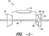
- FIG. 1 illustrates a schematic diagram of a gas turbine 10.
- the gas turbine 10 generally includes a compressor section 12, a plurality of combustors (not shown) disposed within a combustor section 14, and a turbine section 16. Additionally, the system 10 may include a shaft 18 coupled between the compressor section 12 and the turbine section 16.
- the turbine section 16 may generally include a turbine rotor 20 having a plurality of rotor disks 22 (one of which is shown) and a plurality of turbine buckets 24 extending radially outwardly from and being coupled to each rotor disk 22 for rotation therewith. Each rotor disk 22 may, in turn, be coupled to a portion of the shaft 18 extending through the turbine section 16.
- the compressor section 12 supplies compressed air to the combustors of the combustor section 14. Air and fuel are mixed and burned within each combustor and hot gases of combustion flow in a hot gas path from the combustor section 14 to the turbine section 16, wherein energy is extracted from the hot gases by the turbine buckets 24.
- the energy extracted by the turbine buckets 24 is used to rotate to the rotor disks 22 which may, in turn, rotate the shaft 18. The mechanical rotational energy may then be used to power the compressor section 12 and generate electricity.
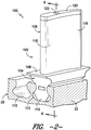
- the blade assembly 100 includes a turbine bucket 102 having a root portion 104 and an airfoil 106.
- the root portion 104 may include a substantially planar platform 108 generally defining the radially inner boundary of the hot gases of combustion flowing through the turbine section 16 of the gas turbine 10 and a root 110 extending radially inwardly from the platform 108.
- the root 110 may generally serve as an attachment mechanism for coupling the turbine bucket 102 to one of the rotor disks 22 (only a portion of which is shown) of the turbine rotor 20.
- each rotor disk 22 may define a plurality of dovetail-shaped slots 112 (two of which are shown) spaced apart around the outer circumference of the disk 22.
- the root 110 may have a corresponding dovetail shape to allow the root 110 to be received within the slot 112.
- the root 110 and/or slots 112 may have any other suitable shape and/or configuration that allows the turbine bucket 102 to be coupled to the rotor disk 22.
- the airfoil 106 of the turbine bucket 102 may generally extend radially outwardly from the platform 108 so as to project into the hot gas path of the combustion gases flowing through turbine section 16.
- the airfoil 106 extends radially outwardly from the platform 108 to an airfoil tip 114 ( FIG. 3 ).
- the airfoil 114 may generally define an aerodynamic shape.
- the airfoil 114 may be shaped so as to have a pressure side 116 and a suction side 118 configured to facilitate the capture and conversion of the kinetic energy of the combustion gases into usable rotational energy.
- the airfoil 114 may generally have a hollow cross-section.
- the airfoil 114 may have a solid or a substantially solid cross-section.
- the turbine bucket 102 may generally be formed from any suitable materials known in the art. However, in several embodiments of the present subject matter, the turbine bucket 102 may be formed from a composite material, such as a ceramic matrix composite (CMC) material. It should also be appreciated that, in several embodiments, the airfoil 106 and the root portion 104 may be formed integrally as a single component.
- CMC ceramic matrix composite
- the blade assembly 100 may also include various other components. As shown in FIG. 2 , the blade assembly 100 includes a separate tip cover 120 coupled to the airfoil 106 and a compression rod 122 (only a portion of which is shown) extending radially within the turbine bucket 102.
- FIGS. 3-5 several views of the various components of the blade assembly 100 shown in FIG. 2 are illustrated in accordance with aspects of the present subject matter.
- FIG. 3 illustrates an exploded view of the blade assembly 100 shown in FIG. 2 .
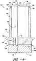
- FIG. 4 illustrates a cross-sectional view of the blade assembly 100 shown in FIG. 2 , taken along line 4-4.
- FIG. 5 illustrates a close-up view of one embodiment of a portion of the compression rod 122 and a portion of a pair clamp plates 124, 125 of the blade assembly 100.
- the tip cover 120 of the blade assembly 100 is positioned over and/or around the airfoil 106 at the airfoil tip 114.
- the airfoil 106 may be designed to have a stepped reduction in size at a location adjacent to the airfoil tip 114 such that a circumferentially extending edge 126 is defined in the airfoil 106.
- the tip cover 120 may generally include a radially extending lip 128 configured to engage the circumferential edge 126 when the tip cover 120 is positioned over the airfoil tip 114.
- the lip 128 may rest upon and be supported by the circumferential edge 126 when the tip cover 120 is coupled to the airfoil 106.
- the tip cover 120 and/or the airfoil 106 may have any other suitable configuration that allows the tip cover 120 to the coupled to the airfoil 106 at the airfoil tip 114.
- tip cover 120 may generally be configured to have a shape or profile corresponding to the shape or profile of the airfoil 114.
- the tip cover 120 may have an aerodynamic profile generally corresponding to the aerodynamic profile of the airfoil 106 at the circumferential edge 126.
- a generally flush and continuous aerodynamic surface may be defined at the interface between the airfoil 106 and the tip cover 120.
- tip cover 120 may generally be formed from any suitable materials known in the art. However, in several embodiments, similarly to the turbine bucket 102, tip cover 120 may be formed from a suitable composite material, such as a CMC material.
- the compression rod 122 of the blade assembly 100 is installed within the turbine bucket 102 so as to be tightly anchored and/or coupled at opposing ends of the airfoil 106.
- the compression rod 122 includes a first end 130 coupled to the tip cover 120 and a second end 132 coupled to the root portion 104 of the turbine bucket 102.
- the compression rod 122 extends may radially within the turbine bucket 102 along the entire length of the airfoil 106 and, thus, is capable of applying a clamping or compressive force against the airfoil 106 during operation of the gas turbine 10.
- the compression rod 122 may provide a radially acting force against the airfoil 106 in order to reduce the likelihood of creep and other forms of material relaxations and/or property degradation from occurring as the airfoil 106 thermally expands in response to increasing temperatures within the gas turbine 10.
- the first end 130 of the compression rod 122 is anchored against and/or coupled to the tip cover 120.
- the tip cover 120 defines an opening 134 having suitable dimensions to allow the compression rod 122 to be radially inserted within the turbine bucket 102.
- the opening 134 may be sized such that the second end 132 of the compression rod 122 may be inserted through the opening 134 and moved radially inwardly towards the root portion 104 of the turbine bucket 102.
- the first end 130 of the compression rod 122 may generally include an outwardly extending projection or flange 136 configured to catch against and/or engage a portion of the tip cover 120 when the rod 122 is inserted through the opening 134.
- the flange 136 may have a conical shape generally defining a tapered profile.
- the opening 134 defined in the tip cover 120 may have a conical shape and may define a tapered profile generally corresponding to the tapered profile of the flange 136.
- the flange 136 may engage the tip cover 120 at the opening 134.
- the flange 136 may generally be recessed within the tip cover 120.
- the flange 136 may be recessed within the tip cover 120 such that the first end 130 of the compression rod 122 is substantially flush with an outer surface 138 of the tip cover 120.
- the compression rod 122 and/or the tip cover 120 may have any other suitable configuration that allows the first end 130 of the compression rod 122 to be anchored against and/or coupled to the tip cover 120.
- the flange 136 may be dimensionally larger than the opening 134 defined in the tip cover 120 such that the flange 136 may be engaged against the outer surface 138 of the tip cover 120 when the compression rod 122 is inserted through the tip cover 122.
- the first end 130 of the compression rod 122 may be welded to the tip cover 120 and/or the first end 130 may be threaded to allow the compression rod 122 to be screwed into a corresponding threaded hole (not shown) defined in the tip cover 120.
- the second end 132 of the compression rod 122 extends radially within the turbine bucket 102 to a location within the root portion 104 of the bucket 102 when the compression rod 122 is installed through the tip cover 120.
- an internal cavity 140 may generally be defined in the root potion 104 for receiving the second end 132 of the compression rod 122.
- the internal cavity 140 may extend radially within the root portion 104 any suitable distance 142 from the platform 108 that allows the compression rod 122 to be fully inserted within the turbine bucket 102 (i.e., such that the first end 130 of the compression rod 122 is engaged against the tip cover 120).
- the internal cavity 140 may be defined through the entire root portion 104, such as by extending radially from the platform 108 to a bottom surface 144 ( FIG. 4 ) of the root portion 104. Further, it should be appreciated that, in embodiments in which the airfoil 106 is not hollow, the internal cavity 140 may also be configured to extend radially outwardly from the platform 108 to the tip cover 120 so as to accommodate the compression rod 122 within the turbine bucket 102.
- the second end 132 of the compression rod 122 is anchored against and/or coupled to the root portion 104.
- the second end 132 is anchored against and/or coupled to the root portion 104 through first and second clamp plates 124, 125 configured to be received within a channel 146 defined in the root portion 106.
- the channel 146 may be defined through the entire root portion 104 and, thus, may include a first open end 148 and a second open end 150.
- the first clamp plate 124 may be installed within the channel 146 through the first open end 148 and the second clamp plate 125 may be installed within the channel 146 through the second open end 150.
- FIG. 3 the channel 146 may be defined through the entire root portion 104 and, thus, may include a first open end 148 and a second open end 150.
- the channel 146 may be defined in the root portion 106 at a radial location generally corresponding to the radial location of the second end 132 of the compression rod 122. As such, when the first and second clamp plates 124, 125 are inserted into the channel 146, the second end 132 of the compression rod 122 may be engaged between the clamp plates 124, 125.
- each clamp plate 124, 125 may include a clamping surface 152 having an attachment feature defined therein configured to radially and circumferentially engage a corresponding attachment feature formed in the second end 132 of the compression rod 122.
- a clamping surface 152 having an attachment feature defined therein configured to radially and circumferentially engage a corresponding attachment feature formed in the second end 132 of the compression rod 122.
- one or more circumferential grooves 154 may be formed in the second end 132 of the compression rod 122.
- the clamping surfaces 152 of each clamp plate 124, 125 may include corresponding grooved recesses 156 configured to extend around a portion of the outer perimeter of the second end 132 and engage the circumferential grooves 154.
- the grooved recesses 156 may mate and/or interlock with the circumferential grooves 154, thereby radially retaining the compression rod 122 within the turbine bucket 102.
- the clamp plates 124, 125 and the second end 132 of the compression rod 122 may generally have any other suitable attachment features that permit the compression rod 122 to be radially retained within the turbine bucket 102 when the clamp plates 124, 125 are inserted into the channel 146.
- the second end 132 of the compression rod 122 may include a conical shaped and/or tapered flange (not shown) similar to the flange 136 formed at the first end 130 of the compression rod 122.
- each clamp plate 124, 125 may include corresponding conical shaped and/or tapered recesses (not shown) such that the clamp plates 124, 125 may radially and circumferentially engage the second end 132 of the compression rod 122.
- clamp plates 124, 125 may generally be retained within the channel 145 using any suitable means.
- cover plates (not shown) may be coupled to the root portion 104 at the open ends 148, 150 of the channel 146 to maintain the clamp plates 124, 125 within the channel 146.
- retaining pins (not shown) may be inserted through the root portion 104 and into the clamp plates 124, 124 to prevent the plates 124, 125 from backing out of the channel 146.
- the compression rod 122 may generally be formed from any suitable material known in the art, in as far as its coefficient of thermal expansion is lower or equal to the coefficient of thermal expansion of the airfoil.
- the compression rod 122 may be formed from a composite material, such as a CMC material.
- the compression rod 122 may generally have any suitable cross-sectional shape.
- the compression rod 122 may have a rectangular, elliptical, or triangular cross-sectional shape.
- the compression rod 122 may generally be configured to apply a compressive force between the tip cover 120 and the root portion 104 in order to radially clamp the airfoil 106, thereby suppressing creep and other forms of material relaxations and/or property degradation during operation of the gas turbine 10.
- the compressive loading and/or tension within the compression rod 122 may generally be provided by a variety of different methods.
- the compression rod 122 may be pre-heated prior to being installed within the turbine bucket 102.
- a radially acting, compressive force may be generated between the first and second ends 130, 132 of the compression rod 122.
- the airfoil 106 may be pre-stressed prior to exposure to the operating temperatures within the gas turbine 10. This pre-stressed condition may then be maintained or even increased as the temperatures of the turbine bucket 102 and the compression rod 122 increase during operation of the gas turbine 10.
- the airfoil 106 need not be pre-stressed in order to generate a compressive force between the first and second ends 130, 132 of the compression rod 122.
- the blade assembly 100 may be configured such that the compressive forces are generated during operation of the gas turbine 10.
- a thermal gradient may be created between the airfoil 106 and the compression rod 122 during operation of the gas turbine 10 so that the airfoil 106 is subject to greater thermal expansion than the rod 122.
- the thermal gradient may be created by supplying a cooling fluid (e.g., purge air from the wheel cavity (not shown) of the gas turbine 10) within the turbine bucket 102 to cool the compression rod 122.
- the internal cavity 140 defined in the turbine bucket 102 may be flow communication with a fluid source (not shown) such that fluid may be directed into the cavity 140.
- a compressive force may be generated as the airfoil 106 expands radially relative to the cooler compression rod 122.
- the compression rod 122 may be designed to have a CTE that is less than the CTE of the airfoil 106.
- the airfoil 106 may expand at more than the compression rod 122 as the temperatures of such components increase during operation of the gas turbine 10, thereby generating a compressive force between the airfoil 106 and the tip cover 120.
- the compression rod 122 and the airfoil 106 may be formed from differing materials, with the material used to form the compression rod 122 having a lower CTE than the material used to form the turbine bucket 102. However, it may be desirable to form the compression rod 122 and the airfoil 106 from the same materials.
- the compression rod 122 and the airfoil 106 may be formed from the same composite material, such as the same CMC material.
- the stack sequence and fiber orientation of the composite layers 158, 160, 162, 164 ( FIG. 6 ) used to form the compression rod 122 may be specifically tailored to provide a lower CTE to the compression rod 122 than the airfoil 106.
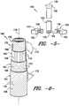
- FIG. 6 illustrates a partial, perspective view of one embodiment of an assembly 166 of composite layers 158, 160, 162, 164 that may be used to form the disclosed compression rod 122, with portions of the outer layers 160, 162, 164 being removed to illustrate portions of the inner layers 158, 160, 162.
- each composite layer 158, 160, 162, 164 includes a matrix material 168 and a plurality of unidirectional reinforcing fibers 170 extending within the matrix material 168.
- the composite layers 158, 160, 162, 164 may include bidirectional or multi-directional fibers 170.
- each composite layer 158, 160, 162, 164 includes a fiber orientation defining a differing fiber angle 172 (measured relative to a centerline 176 of the assembly 166).
- the first innermost composite layer 158 includes fibers 170 oriented at a fiber angle 172 of 135 degrees
- the second adjacent composite layer 160 includes fibers 170 oriented at a fiber angle 172 of 0 degrees
- the third composite layer 162 includes fibers 170 oriented at a fiber angle 172 of 90 degrees
- the fourth outermost composite layer 164 includes fibers 170 oriented at a fiber angle of 45 degrees.
- the fibers 170 contained within each of the composite layers 158, 160, 162, 164 may generally be oriented at any other suitable fiber angle 172, such as from about 0 degrees to about 180 degrees.
- the composite layers 158, 160, 162, 164 may generally be assembled in any suitable stack sequence that provides the desired CTE to the compression rod 122.
- the assembly 160 is stacked in a fiber orientation pattern (135 degrees, 0 degrees, 90 degrees, 45 degrees) that repeats after every fourth composite layer 158, 160, 162, 164.
- the assembly 166 may include any other suitable combination of fiber orientations stacked in any suitable sequence or pattern.
- the assembly 166 may only include composite layers 158, 160, 162, 164 having two differing fiber orientations, such as by having composite layers 158, 160, 162, 164 that alternate between 0 and 90 degree fiber orientations.
- a vast number of different combinations of stack sequences and fiber orientations may be achieved.
- the present subject matter is also directed to an assembly 200 ( FIGS. 7 and 8 ) for applying a compressive force to one or more components used within severe thermal-mechanical environments, such as within gas turbine engines.
- the assembly 200 may comprise the compression rod 122, the tip cover 120 and the clamp plates 124, 125 described above with reference to FIGS. 2-6 and, thus, the assembly 200 may be configured to apply a compressive force to and/or within a turbine bucket 102.
- the assembly 200 may be configured to be utilized with various other suitable high temperature components so as to reduce the likelihood of creep and other forms of material relaxations and/or property degradation from occurring within such components.
- FIGS. 7 and 8 there is illustrated another embodiment of an assembly 200 for applying a compressive force to and/or within a component 202 in accordance with aspects of the present subject matter.
- the assembly 200 generally includes a rod 204, an attachment plate 210, a first clamp plate 218 and a second clamp plate 220.
- the rod 204 may generally be configured the same as or similar to the compression rod 122 described above with reference to FIGS. 2-6 .
- the rod 204 may include a first end 206 anchored against and/or coupled to the component 202 through the attachment plate 210 and a second end 208 anchored against and/or coupled to the component 202 through the first and second clamp plates 218, 220.
- the rod 204 applies a compressive or clamping force to the component 202 as it undergoes thermal expansion to reduce the likelihood of creep and other forms of material relaxations and/or property degradation from occurring.
- the rod 204 having a CTE that is less than the CTE of the component 202, such as by tailoring the stack sequence and/or fiber orientation of the composite layers (not shown) used to form the rod 202.
- the first end 206 of the rod 204 is anchored against and/or coupled to the attachment plate 210, the plate 210 comprising an opening 212 having suitable dimensions to allow the rod 204 to be inserted through the opening 212.
- a diameter 214 of the opening 212 may be chosen such that the second end 208 of the rod 204 may be inserted through the opening 212 and into the component 202.
- the first end 206 of the rod 204 may generally include an outwardly extending projection or flange 216 configured to catch against and/or engage a portion of the attachment plate 210 when the rod 204 is inserted through the opening 212.
- the flange 216 may diverge outwardly from the rod 204 so as to define a tapered profile.
- the opening 212 defined in the attachment plate 210 may have a tapered profile generally corresponding to the tapered profile of the flange 216.
- the rod 204 and/or the opening 212 may have any other suitable configuration that allows the first end 206 of the rod 204 to be anchored against and/or coupled to the attachment plate 210.
- the attachment plate 210 may generally have any suitable configuration that allows the plate 210 to be coupled to and/or engaged against a portion of the component 202 so that the compressive force applied through the rod 204 may be transferred into the component 202.
- the attachment plate 210 is configured as a tip cover 122 and may have an aerodynamic shape designed to allow the plate 210 to be coupled to the turbine bucket 102 at the airfoil tip 114.
- the dimensions and/or shape of the attachment plate 210 may generally vary depending on the component 202 in which the assembly 200 is being installed.
- the opening 212 may be defined in the component 202 such that the first end 206 of the rod 204 is configured to be directly engaged against the component 202.
- the attachment plate 210 comprises the portion of the component 202 in which the opening 212 is formed.
- the second end 208 of the rod 204 is anchored against and/or coupled to the component 202 through the first and second clamp plates 218, 220.
- the first and second clamp plates 218, 220 are received within a corresponding channel 146 ( FIGS.3 and 4 ) defined within the component 202.
- each clamp plate 218, 220 may include a clamping surface 222 having an attachment feature defined therein configured to radially and circumferentially engage a corresponding attachment feature formed in the second end 208 of the rod 204.
- an outwardly extending flange 224 may be formed in the second end 208 of the rod 204.
- the flange 224 may diverge outwardly from the rod 204 so as to define a tapered profile.
- the clamping surfaces 222 of the clamp plates 218, 220 may include corresponding tapered recesses 226 configured to extend around a portion of the outer perimeter of the second end 208 and engage the flange 224.
- the flange 224 may be encased within the tapered recesses 226, thereby preventing longitudinal movement of the rod 204 within the component 202.
- the clamp plates 218, 220 and the second end 208 of the rod 204 may generally have any other suitable attachment features.
- the second end 208 may define circumferential grooves 154 ( FIG. 5 ) configured to be received within corresponding grooved recesses 156 ( FIG. 5 ) formed in the clamp plates 218, 220.
- the rod 204 may generally be formed from any suitable material known in the art, in as far as its thermal expansion coefficient is equal or lower than the thermal expansion coefficient of the airfoil. However, in several embodiments, the rod 204 may be formed from a composite material, such as a CMC material. It should also be appreciated that, although the rod 204 is depicted herein as having a substantially circular cross-sectional shape, the rod 204 may generally have any suitable cross-sectional shape. For example, in alternative embodiments, the rod 204 may have a rectangular, elliptical, or triangular cross-sectional shape.
Landscapes
- Engineering & Computer Science (AREA)
- Chemical & Material Sciences (AREA)
- Mechanical Engineering (AREA)
- General Engineering & Computer Science (AREA)
- Ceramic Engineering (AREA)
- Materials Engineering (AREA)
- Architecture (AREA)
- Turbine Rotor Nozzle Sealing (AREA)
Claims (6)
- Turbinenlaufschaufelanordnung (100), umfassend:eine Turbinenlaufschaufel (102), wobei die Turbinenlaufschaufel (102) ein Fußteil (104) und eine Tragfläche (106) einschließt, wobei sich die Tragfläche (106) radial von dem Fußteil (104) zu einer Tragflächenspitze (114) erstreckt;eine Spitzenabdeckung (120), die mit der Tragfläche (106) an der Tragflächenspitze (114) gekoppelt ist, undeine Verbundstange (122), die sich innerhalb der Turbinenlaufschaufel (102) erstreckt, wobei die Verbundstange (122) ein erstes Ende (130) einschließt, das mit der Tragfläche (106) an der Tragflächenspitze (114) gekoppelt ist und wobei das erste Ende mit der Spitzenabdeckung (120) gekoppelt ist und ein zweites Ende (132) mit dem Fußteil (104) gekoppelt ist, und die Anordnung weiter Mittel zur Kopplung des zweiten Endes (132) der Verbundstange (122) mit dem Fußteil (104) umfasst,wobei die Anordnung dadurch gekennzeichnet ist, dass das zweite Ende (132) konfiguriert ist, um durch eine Öffnung (134), die in der Spitzenabdeckung definiert ist, radial in die Turbinenlaufschaufel (102) eingeführt zu werden; undwobei die Mittel zur Kopplung eine erste Klemmplatte (124) und eine zweite Klemmplatte (125) umfassen, die konfiguriert sind, um in einem Kanal (146) aufgenommen zu werden, der durch das Fußteil (104) definiert ist,wobei ein Wärmeausdehnungskoeffizient der Verbundstange (122) kleiner oder gleich einem Wärmeausdehnungskoeffizienten der Tragfläche (106) ist.
- Turbinenlaufschaufelanordnung (100) nach Anspruch 1, wobei die Turbinenlaufschaufel (102) und die Verbundstange (122) aus einem Keramikmatrix-Verbundmaterial gebildet sind.
- Turbinenlaufschaufelanordnung (100) nach Anspruch 1 oder 2, wobei die Verbundstange (122) aus einer Vielzahl von Verbundschichten (158) gebildet ist, wobei die Vielzahl von Verbundschichten (158) mindestens zwei unterschiedliche Faserorientierungen (172) einschließen.
- Turbinenlaufschaufelanordnung (100) nach einem der vorstehenden Ansprüche, wobei jede der ersten und zweiten Klemmplatten (124, 125) eine Klemmfläche (152) definiert, die konfiguriert ist, um mit dem zweiten Ende (132) der Verbundstange (122) in Eingriff zu kommen, wenn die erste und die zweite Klemmplatte (124, 125) in den Kanal (146) eingeführt sind.
- Turbinenlaufschaufelanordnung (100) nach Anspruch 4, wobei eine Nut (154) in dem zweiten Ende (132) der Verbundstange (122) gebildet wird, wobei die Klemmfläche (152) eine mit Nuten versehene Ausnehmung (156) einschließt, die konfiguriert ist, um mit der Nut (154) in Eingriff zu kommen.
- Turbinenlaufschaufelanordnung (100) nach einem der vorstehenden Ansprüche, wobei ein Wärmeausdehnungskoeffizient der Verbundstange (122) geringer ist als ein Wärmeausdehnungskoeffizient der Tragfläche (106).
Applications Claiming Priority (1)
| Application Number | Priority Date | Filing Date | Title |
|---|---|---|---|
| US13/049,179 US8475132B2 (en) | 2011-03-16 | 2011-03-16 | Turbine blade assembly |
Publications (3)
| Publication Number | Publication Date |
|---|---|
| EP2500519A2 EP2500519A2 (de) | 2012-09-19 |
| EP2500519A3 EP2500519A3 (de) | 2013-08-28 |
| EP2500519B1 true EP2500519B1 (de) | 2018-10-03 |
Family
ID=45851410
Family Applications (1)
| Application Number | Title | Priority Date | Filing Date |
|---|---|---|---|
| EP12159191.1A Active EP2500519B1 (de) | 2011-03-16 | 2012-03-13 | Turbinenlaufschaufel |
Country Status (3)
| Country | Link |
|---|---|
| US (1) | US8475132B2 (de) |
| EP (1) | EP2500519B1 (de) |
| CN (1) | CN102678188B (de) |
Families Citing this family (31)
| Publication number | Priority date | Publication date | Assignee | Title |
|---|---|---|---|---|
| US20140199174A1 (en) * | 2013-01-11 | 2014-07-17 | General Electric Company | Method of forming a ceramic matrix composite component, a ceramic matrix composite component and a tip member |
| WO2014149116A2 (en) * | 2013-02-23 | 2014-09-25 | Shuck Quinlan Y | Gas turbine engine component |
| WO2014197119A2 (en) * | 2013-04-16 | 2014-12-11 | United Technologies Corporation | Rotors with modulus mistuned airfoils |
| DE102013219774A1 (de) * | 2013-09-30 | 2015-04-02 | MTU Aero Engines AG | Schaufel für eine Gasturbine |
| US9896945B2 (en) * | 2013-11-25 | 2018-02-20 | General Electric Company | Process of producing a ceramic matrix composite turbine bucket, insert for a ceramic matrix composite turbine bucket and ceramic matrix composite turbine bucket |
| EP2902588B1 (de) * | 2014-01-31 | 2020-06-24 | Ansaldo Energia IP UK Limited | Verbundstoffturbinenschaufel für Hochtemperaturanwendungen |
| CN104074555B (zh) * | 2014-07-09 | 2015-09-16 | 苏州市汉诺威升降台有限公司 | 动力叶片 |
| CA2915234A1 (en) * | 2015-01-13 | 2016-07-13 | Rolls-Royce Corporation | Turbine wheel with clamped blade attachment |
| US10472975B2 (en) * | 2015-09-03 | 2019-11-12 | General Electric Company | Damper pin having elongated bodies for damping adjacent turbine blades |
| FI127275B (en) * | 2015-12-01 | 2018-02-28 | Lappeenrannan Teknillinen Yliopisto | Radial turbine impeller and its manufacturing process |
| US10428658B2 (en) * | 2016-11-17 | 2019-10-01 | United Technologies Corporation | Airfoil with panel fastened to core structure |
| US10605088B2 (en) * | 2016-11-17 | 2020-03-31 | United Technologies Corporation | Airfoil endwall with partial integral airfoil wall |
| FR3067390B1 (fr) * | 2017-04-10 | 2019-11-29 | Safran | Aube de turbine presentant une structure amelioree |
| US10724380B2 (en) * | 2017-08-07 | 2020-07-28 | General Electric Company | CMC blade with internal support |
| US11802486B2 (en) * | 2017-11-13 | 2023-10-31 | General Electric Company | CMC component and fabrication using mechanical joints |
| US10519777B2 (en) * | 2018-05-14 | 2019-12-31 | General Electric Company | Tip member for blade structure and related method to form turbomachine component |
| US10738628B2 (en) * | 2018-05-25 | 2020-08-11 | General Electric Company | Joint for band features on turbine nozzle and fabrication |
| US10612399B2 (en) | 2018-06-01 | 2020-04-07 | Rolls-Royce North American Technologies Inc. | Turbine vane assembly with ceramic matrix composite components |
| US10808560B2 (en) | 2018-06-20 | 2020-10-20 | Rolls-Royce Corporation | Turbine vane assembly with ceramic matrix composite components |
| DE102018210262A1 (de) * | 2018-06-25 | 2020-01-02 | MTU Aero Engines AG | Turbomaschinen-Schaufelanordnung |
| US10605103B2 (en) | 2018-08-24 | 2020-03-31 | Rolls-Royce Corporation | CMC airfoil assembly |
| US10767497B2 (en) | 2018-09-07 | 2020-09-08 | Rolls-Royce Corporation | Turbine vane assembly with ceramic matrix composite components |
| DE102018217501A1 (de) | 2018-10-12 | 2020-04-16 | Siemens Aktiengesellschaft | Verfahren zum Fügen einer modular aufgebauten Heißgaskomponente mittels Schweißen und Hochtemperaturlöten und Komponente |
| US10815795B2 (en) * | 2018-12-20 | 2020-10-27 | General Electric Company | Pre-tension and retention structure for composite fan blade |
| US11008878B2 (en) | 2018-12-21 | 2021-05-18 | Rolls-Royce Plc | Turbine blade with ceramic matrix composite aerofoil and metallic root |
| US10731471B2 (en) * | 2018-12-28 | 2020-08-04 | General Electric Company | Hybrid rotor blades for turbine engines |
| CN109926805A (zh) * | 2019-04-09 | 2019-06-25 | 重庆水轮机厂有限责任公司 | 一种组合式混流水泵模型叶轮制造方法 |
| EP3751098A1 (de) * | 2019-06-13 | 2020-12-16 | Siemens Aktiengesellschaft | Verbesserte klinge |
| US11255200B2 (en) | 2020-01-28 | 2022-02-22 | Rolls-Royce Plc | Gas turbine engine with pre-conditioned ceramic matrix composite components |
| US11454118B2 (en) | 2020-09-04 | 2022-09-27 | General Electric Company | Gas turbine engine rotor blade having a root section with composite and metallic portions |
| US12571314B2 (en) * | 2023-07-07 | 2026-03-10 | General Electric Company | Composite airfoil assembly for a turbine engine |
Family Cites Families (15)
| Publication number | Priority date | Publication date | Assignee | Title |
|---|---|---|---|---|
| US2328856A (en) | 1940-03-20 | 1943-09-07 | Hydril Co | Composite drill collar |
| US3269609A (en) | 1964-12-31 | 1966-08-30 | Bridgeport Metal Goods Mfg Co | Compositie container cap and outer collar |
| FR2195255A5 (de) * | 1972-08-04 | 1974-03-01 | Snecma | |
| DE2834864C3 (de) * | 1978-08-09 | 1981-11-19 | MTU Motoren- und Turbinen-Union München GmbH, 8000 München | Laufschaufel für eine Gasturbine |
| DE3306896A1 (de) * | 1983-02-26 | 1984-08-30 | MTU Motoren- und Turbinen-Union München GmbH, 8000 München | Heissgasbeaufschlagte turbinenschaufel mit metallenem stuetzkern und umgebendem keramischen schaufelblatt |
| US4790721A (en) | 1988-04-25 | 1988-12-13 | Rockwell International Corporation | Blade assembly |
| US7080971B2 (en) | 2003-03-12 | 2006-07-25 | Florida Turbine Technologies, Inc. | Cooled turbine spar shell blade construction |
| US7153096B2 (en) | 2004-12-02 | 2006-12-26 | Siemens Power Generation, Inc. | Stacked laminate CMC turbine vane |
| US7510379B2 (en) * | 2005-12-22 | 2009-03-31 | General Electric Company | Composite blading member and method for making |
| AT503270B1 (de) * | 2006-03-09 | 2008-03-15 | Arc Seibersdorf Res Gmbh | Verbundwerkstoff und verfahren zu seiner herstellung |
| US7625170B2 (en) * | 2006-09-25 | 2009-12-01 | General Electric Company | CMC vane insulator and method of use |
| US7887937B2 (en) * | 2007-01-23 | 2011-02-15 | The Boeing Company | Thermal insulation assemblies and methods for fabricating the same |
| DE102007027465A1 (de) * | 2007-06-14 | 2008-12-18 | Rolls-Royce Deutschland Ltd & Co Kg | Gasturbinenschaufel mit modularem Aufbau |
| US8033790B2 (en) * | 2008-09-26 | 2011-10-11 | Siemens Energy, Inc. | Multiple piece turbine engine airfoil with a structural spar |
| PL2213405T3 (pl) | 2009-02-02 | 2011-10-31 | Pepperl & Fuchs Gmbh | Połączenie metal-tworzywo sztuczne |
-
2011
- 2011-03-16 US US13/049,179 patent/US8475132B2/en active Active
-
2012
- 2012-03-13 EP EP12159191.1A patent/EP2500519B1/de active Active
- 2012-03-16 CN CN201210080576.4A patent/CN102678188B/zh active Active
Non-Patent Citations (1)
| Title |
|---|
| None * |
Also Published As
| Publication number | Publication date |
|---|---|
| CN102678188A (zh) | 2012-09-19 |
| EP2500519A3 (de) | 2013-08-28 |
| EP2500519A2 (de) | 2012-09-19 |
| US20120237355A1 (en) | 2012-09-20 |
| CN102678188B (zh) | 2015-02-11 |
| US8475132B2 (en) | 2013-07-02 |
Similar Documents
| Publication | Publication Date | Title |
|---|---|---|
| EP2500519B1 (de) | Turbinenlaufschaufel | |
| CN109072705B (zh) | 在冷态下弹性保持的涡轮环组件 | |
| US8740552B2 (en) | Low-ductility turbine shroud and mounting apparatus | |
| US8079807B2 (en) | Mounting apparatus for low-ductility turbine shroud | |
| CA2781944C (en) | Chordal mounting arrangement for low-ductility turbine shroud | |
| US8579580B2 (en) | Mounting apparatus for low-ductility turbine shroud | |
| US7950234B2 (en) | Ceramic matrix composite turbine engine components with unitary stiffening frame | |
| US10392958B2 (en) | Hybrid blade outer air seal for gas turbine engine | |
| US8251652B2 (en) | Gas turbine vane platform element | |
| JP5312863B2 (ja) | 押付けプレートシール | |
| US8398374B2 (en) | Method and apparatus for a segmented turbine bucket assembly | |
| EP3106614B1 (de) | Rotordämpfer | |
| US10605086B2 (en) | Turbine engines with ceramic vanes and methods for manufacturing the same | |
| EP2578807A2 (de) | Tragfläche für Turbinensystem | |
| US10519779B2 (en) | Radial CMC wall thickness variation for stress response | |
| US11105209B2 (en) | Turbine blade tip shroud | |
| US10577949B2 (en) | Component for a gas turbine engine | |
| US20210087936A1 (en) | Detuned turbine blade tip shrouds | |
| CN115135851A (zh) | 用于轮辋式转子的温障涂层 | |
| US11821319B2 (en) | Frangible airfoil with shape memory alloy | |
| CN115680783B (zh) | 具有形状记忆合金的易碎翼型件 | |
| WO2018236510A1 (en) | ANNULAR SEGMENT WITH ASSEMBLED RAILS |
Legal Events
| Date | Code | Title | Description |
|---|---|---|---|
| PUAI | Public reference made under article 153(3) epc to a published international application that has entered the european phase |
Free format text: ORIGINAL CODE: 0009012 |
|
| AK | Designated contracting states |
Kind code of ref document: A2 Designated state(s): AL AT BE BG CH CY CZ DE DK EE ES FI FR GB GR HR HU IE IS IT LI LT LU LV MC MK MT NL NO PL PT RO RS SE SI SK SM TR |
|
| AX | Request for extension of the european patent |
Extension state: BA ME |
|
| PUAL | Search report despatched |
Free format text: ORIGINAL CODE: 0009013 |
|
| AK | Designated contracting states |
Kind code of ref document: A3 Designated state(s): AL AT BE BG CH CY CZ DE DK EE ES FI FR GB GR HR HU IE IS IT LI LT LU LV MC MK MT NL NO PL PT RO RS SE SI SK SM TR |
|
| AX | Request for extension of the european patent |
Extension state: BA ME |
|
| RIC1 | Information provided on ipc code assigned before grant |
Ipc: F01D 5/28 20060101ALI20130719BHEP Ipc: B23P 15/04 20060101ALI20130719BHEP Ipc: F01D 5/14 20060101AFI20130719BHEP |
|
| 17P | Request for examination filed |
Effective date: 20140228 |
|
| RBV | Designated contracting states (corrected) |
Designated state(s): AL AT BE BG CH CY CZ DE DK EE ES FI FR GB GR HR HU IE IS IT LI LT LU LV MC MK MT NL NO PL PT RO RS SE SI SK SM TR |
|
| GRAP | Despatch of communication of intention to grant a patent |
Free format text: ORIGINAL CODE: EPIDOSNIGR1 |
|
| STAA | Information on the status of an ep patent application or granted ep patent |
Free format text: STATUS: GRANT OF PATENT IS INTENDED |
|
| INTG | Intention to grant announced |
Effective date: 20180219 |
|
| GRAJ | Information related to disapproval of communication of intention to grant by the applicant or resumption of examination proceedings by the epo deleted |
Free format text: ORIGINAL CODE: EPIDOSDIGR1 |
|
| STAA | Information on the status of an ep patent application or granted ep patent |
Free format text: STATUS: REQUEST FOR EXAMINATION WAS MADE |
|
| GRAS | Grant fee paid |
Free format text: ORIGINAL CODE: EPIDOSNIGR3 |
|
| STAA | Information on the status of an ep patent application or granted ep patent |
Free format text: STATUS: GRANT OF PATENT IS INTENDED |
|
| GRAP | Despatch of communication of intention to grant a patent |
Free format text: ORIGINAL CODE: EPIDOSNIGR1 |
|
| INTC | Intention to grant announced (deleted) | ||
| INTG | Intention to grant announced |
Effective date: 20180605 |
|
| GRAA | (expected) grant |
Free format text: ORIGINAL CODE: 0009210 |
|
| STAA | Information on the status of an ep patent application or granted ep patent |
Free format text: STATUS: THE PATENT HAS BEEN GRANTED |
|
| AK | Designated contracting states |
Kind code of ref document: B1 Designated state(s): AL AT BE BG CH CY CZ DE DK EE ES FI FR GB GR HR HU IE IS IT LI LT LU LV MC MK MT NL NO PL PT RO RS SE SI SK SM TR |
|
| REG | Reference to a national code |
Ref country code: GB Ref legal event code: FG4D |
|
| REG | Reference to a national code |
Ref country code: CH Ref legal event code: EP Ref country code: AT Ref legal event code: REF Ref document number: 1048806 Country of ref document: AT Kind code of ref document: T Effective date: 20181015 |
|
| REG | Reference to a national code |
Ref country code: IE Ref legal event code: FG4D Ref country code: DE Ref legal event code: R096 Ref document number: 602012051676 Country of ref document: DE |
|
| REG | Reference to a national code |
Ref country code: NL Ref legal event code: MP Effective date: 20181003 |
|
| REG | Reference to a national code |
Ref country code: LT Ref legal event code: MG4D |
|
| REG | Reference to a national code |
Ref country code: AT Ref legal event code: MK05 Ref document number: 1048806 Country of ref document: AT Kind code of ref document: T Effective date: 20181003 |
|
| PG25 | Lapsed in a contracting state [announced via postgrant information from national office to epo] |
Ref country code: NL Free format text: LAPSE BECAUSE OF FAILURE TO SUBMIT A TRANSLATION OF THE DESCRIPTION OR TO PAY THE FEE WITHIN THE PRESCRIBED TIME-LIMIT Effective date: 20181003 |
|
| PG25 | Lapsed in a contracting state [announced via postgrant information from national office to epo] |
Ref country code: BG Free format text: LAPSE BECAUSE OF FAILURE TO SUBMIT A TRANSLATION OF THE DESCRIPTION OR TO PAY THE FEE WITHIN THE PRESCRIBED TIME-LIMIT Effective date: 20190103 Ref country code: ES Free format text: LAPSE BECAUSE OF FAILURE TO SUBMIT A TRANSLATION OF THE DESCRIPTION OR TO PAY THE FEE WITHIN THE PRESCRIBED TIME-LIMIT Effective date: 20181003 Ref country code: IS Free format text: LAPSE BECAUSE OF FAILURE TO SUBMIT A TRANSLATION OF THE DESCRIPTION OR TO PAY THE FEE WITHIN THE PRESCRIBED TIME-LIMIT Effective date: 20190203 Ref country code: LT Free format text: LAPSE BECAUSE OF FAILURE TO SUBMIT A TRANSLATION OF THE DESCRIPTION OR TO PAY THE FEE WITHIN THE PRESCRIBED TIME-LIMIT Effective date: 20181003 Ref country code: NO Free format text: LAPSE BECAUSE OF FAILURE TO SUBMIT A TRANSLATION OF THE DESCRIPTION OR TO PAY THE FEE WITHIN THE PRESCRIBED TIME-LIMIT Effective date: 20190103 Ref country code: CZ Free format text: LAPSE BECAUSE OF FAILURE TO SUBMIT A TRANSLATION OF THE DESCRIPTION OR TO PAY THE FEE WITHIN THE PRESCRIBED TIME-LIMIT Effective date: 20181003 Ref country code: AT Free format text: LAPSE BECAUSE OF FAILURE TO SUBMIT A TRANSLATION OF THE DESCRIPTION OR TO PAY THE FEE WITHIN THE PRESCRIBED TIME-LIMIT Effective date: 20181003 Ref country code: LV Free format text: LAPSE BECAUSE OF FAILURE TO SUBMIT A TRANSLATION OF THE DESCRIPTION OR TO PAY THE FEE WITHIN THE PRESCRIBED TIME-LIMIT Effective date: 20181003 Ref country code: HR Free format text: LAPSE BECAUSE OF FAILURE TO SUBMIT A TRANSLATION OF THE DESCRIPTION OR TO PAY THE FEE WITHIN THE PRESCRIBED TIME-LIMIT Effective date: 20181003 Ref country code: PL Free format text: LAPSE BECAUSE OF FAILURE TO SUBMIT A TRANSLATION OF THE DESCRIPTION OR TO PAY THE FEE WITHIN THE PRESCRIBED TIME-LIMIT Effective date: 20181003 Ref country code: FI Free format text: LAPSE BECAUSE OF FAILURE TO SUBMIT A TRANSLATION OF THE DESCRIPTION OR TO PAY THE FEE WITHIN THE PRESCRIBED TIME-LIMIT Effective date: 20181003 |
|
| PG25 | Lapsed in a contracting state [announced via postgrant information from national office to epo] |
Ref country code: SE Free format text: LAPSE BECAUSE OF FAILURE TO SUBMIT A TRANSLATION OF THE DESCRIPTION OR TO PAY THE FEE WITHIN THE PRESCRIBED TIME-LIMIT Effective date: 20181003 Ref country code: AL Free format text: LAPSE BECAUSE OF FAILURE TO SUBMIT A TRANSLATION OF THE DESCRIPTION OR TO PAY THE FEE WITHIN THE PRESCRIBED TIME-LIMIT Effective date: 20181003 Ref country code: GR Free format text: LAPSE BECAUSE OF FAILURE TO SUBMIT A TRANSLATION OF THE DESCRIPTION OR TO PAY THE FEE WITHIN THE PRESCRIBED TIME-LIMIT Effective date: 20190104 Ref country code: RS Free format text: LAPSE BECAUSE OF FAILURE TO SUBMIT A TRANSLATION OF THE DESCRIPTION OR TO PAY THE FEE WITHIN THE PRESCRIBED TIME-LIMIT Effective date: 20181003 Ref country code: PT Free format text: LAPSE BECAUSE OF FAILURE TO SUBMIT A TRANSLATION OF THE DESCRIPTION OR TO PAY THE FEE WITHIN THE PRESCRIBED TIME-LIMIT Effective date: 20190203 |
|
| REG | Reference to a national code |
Ref country code: DE Ref legal event code: R097 Ref document number: 602012051676 Country of ref document: DE |
|
| PG25 | Lapsed in a contracting state [announced via postgrant information from national office to epo] |
Ref country code: IT Free format text: LAPSE BECAUSE OF FAILURE TO SUBMIT A TRANSLATION OF THE DESCRIPTION OR TO PAY THE FEE WITHIN THE PRESCRIBED TIME-LIMIT Effective date: 20181003 Ref country code: DK Free format text: LAPSE BECAUSE OF FAILURE TO SUBMIT A TRANSLATION OF THE DESCRIPTION OR TO PAY THE FEE WITHIN THE PRESCRIBED TIME-LIMIT Effective date: 20181003 |
|
| PLBE | No opposition filed within time limit |
Free format text: ORIGINAL CODE: 0009261 |
|
| STAA | Information on the status of an ep patent application or granted ep patent |
Free format text: STATUS: NO OPPOSITION FILED WITHIN TIME LIMIT |
|
| PG25 | Lapsed in a contracting state [announced via postgrant information from national office to epo] |
Ref country code: SM Free format text: LAPSE BECAUSE OF FAILURE TO SUBMIT A TRANSLATION OF THE DESCRIPTION OR TO PAY THE FEE WITHIN THE PRESCRIBED TIME-LIMIT Effective date: 20181003 Ref country code: EE Free format text: LAPSE BECAUSE OF FAILURE TO SUBMIT A TRANSLATION OF THE DESCRIPTION OR TO PAY THE FEE WITHIN THE PRESCRIBED TIME-LIMIT Effective date: 20181003 Ref country code: RO Free format text: LAPSE BECAUSE OF FAILURE TO SUBMIT A TRANSLATION OF THE DESCRIPTION OR TO PAY THE FEE WITHIN THE PRESCRIBED TIME-LIMIT Effective date: 20181003 Ref country code: SK Free format text: LAPSE BECAUSE OF FAILURE TO SUBMIT A TRANSLATION OF THE DESCRIPTION OR TO PAY THE FEE WITHIN THE PRESCRIBED TIME-LIMIT Effective date: 20181003 |
|
| 26N | No opposition filed |
Effective date: 20190704 |
|
| PG25 | Lapsed in a contracting state [announced via postgrant information from national office to epo] |
Ref country code: MC Free format text: LAPSE BECAUSE OF FAILURE TO SUBMIT A TRANSLATION OF THE DESCRIPTION OR TO PAY THE FEE WITHIN THE PRESCRIBED TIME-LIMIT Effective date: 20181003 Ref country code: SI Free format text: LAPSE BECAUSE OF FAILURE TO SUBMIT A TRANSLATION OF THE DESCRIPTION OR TO PAY THE FEE WITHIN THE PRESCRIBED TIME-LIMIT Effective date: 20181003 |
|
| REG | Reference to a national code |
Ref country code: CH Ref legal event code: PL |
|
| GBPC | Gb: european patent ceased through non-payment of renewal fee |
Effective date: 20190313 |
|
| PG25 | Lapsed in a contracting state [announced via postgrant information from national office to epo] |
Ref country code: LU Free format text: LAPSE BECAUSE OF NON-PAYMENT OF DUE FEES Effective date: 20190313 |
|
| REG | Reference to a national code |
Ref country code: BE Ref legal event code: MM Effective date: 20190331 |
|
| PG25 | Lapsed in a contracting state [announced via postgrant information from national office to epo] |
Ref country code: GB Free format text: LAPSE BECAUSE OF NON-PAYMENT OF DUE FEES Effective date: 20190313 Ref country code: LI Free format text: LAPSE BECAUSE OF NON-PAYMENT OF DUE FEES Effective date: 20190331 Ref country code: CH Free format text: LAPSE BECAUSE OF NON-PAYMENT OF DUE FEES Effective date: 20190331 Ref country code: IE Free format text: LAPSE BECAUSE OF NON-PAYMENT OF DUE FEES Effective date: 20190313 |
|
| PG25 | Lapsed in a contracting state [announced via postgrant information from national office to epo] |
Ref country code: FR Free format text: LAPSE BECAUSE OF NON-PAYMENT OF DUE FEES Effective date: 20190331 Ref country code: BE Free format text: LAPSE BECAUSE OF NON-PAYMENT OF DUE FEES Effective date: 20190331 |
|
| PG25 | Lapsed in a contracting state [announced via postgrant information from national office to epo] |
Ref country code: TR Free format text: LAPSE BECAUSE OF FAILURE TO SUBMIT A TRANSLATION OF THE DESCRIPTION OR TO PAY THE FEE WITHIN THE PRESCRIBED TIME-LIMIT Effective date: 20181003 |
|
| PG25 | Lapsed in a contracting state [announced via postgrant information from national office to epo] |
Ref country code: MT Free format text: LAPSE BECAUSE OF NON-PAYMENT OF DUE FEES Effective date: 20190313 |
|
| PG25 | Lapsed in a contracting state [announced via postgrant information from national office to epo] |
Ref country code: CY Free format text: LAPSE BECAUSE OF FAILURE TO SUBMIT A TRANSLATION OF THE DESCRIPTION OR TO PAY THE FEE WITHIN THE PRESCRIBED TIME-LIMIT Effective date: 20181003 |
|
| PG25 | Lapsed in a contracting state [announced via postgrant information from national office to epo] |
Ref country code: HU Free format text: LAPSE BECAUSE OF FAILURE TO SUBMIT A TRANSLATION OF THE DESCRIPTION OR TO PAY THE FEE WITHIN THE PRESCRIBED TIME-LIMIT; INVALID AB INITIO Effective date: 20120313 |
|
| PG25 | Lapsed in a contracting state [announced via postgrant information from national office to epo] |
Ref country code: MK Free format text: LAPSE BECAUSE OF FAILURE TO SUBMIT A TRANSLATION OF THE DESCRIPTION OR TO PAY THE FEE WITHIN THE PRESCRIBED TIME-LIMIT Effective date: 20181003 |
|
| REG | Reference to a national code |
Ref country code: DE Ref legal event code: R081 Ref document number: 602012051676 Country of ref document: DE Owner name: GENERAL ELECTRIC TECHNOLOGY GMBH, CH Free format text: FORMER OWNER: GENERAL ELECTRIC COMPANY, SCHENECTADY, NY, US |
|
| PGFP | Annual fee paid to national office [announced via postgrant information from national office to epo] |
Ref country code: DE Payment date: 20250218 Year of fee payment: 14 |