EP2500263B1 - Verbesserte Rückhaltung für geklebte hohle Ventilatorschaufelabdeckung - Google Patents
Verbesserte Rückhaltung für geklebte hohle Ventilatorschaufelabdeckung Download PDFInfo
- Publication number
- EP2500263B1 EP2500263B1 EP12159600.1A EP12159600A EP2500263B1 EP 2500263 B1 EP2500263 B1 EP 2500263B1 EP 12159600 A EP12159600 A EP 12159600A EP 2500263 B1 EP2500263 B1 EP 2500263B1
- Authority
- EP
- European Patent Office
- Prior art keywords
- fan blade
- trench
- pressure side
- suction side
- rib
- Prior art date
- Legal status (The legal status is an assumption and is not a legal conclusion. Google has not performed a legal analysis and makes no representation as to the accuracy of the status listed.)
- Active
Links
Images


Classifications
-
- B—PERFORMING OPERATIONS; TRANSPORTING
- B64—AIRCRAFT; AVIATION; COSMONAUTICS
- B64C—AEROPLANES; HELICOPTERS
- B64C11/00—Propellers, e.g. of ducted type; Features common to propellers and rotors for rotorcraft
- B64C11/16—Blades
- B64C11/20—Constructional features
- B64C11/24—Hollow blades
-
- F—MECHANICAL ENGINEERING; LIGHTING; HEATING; WEAPONS; BLASTING
- F01—MACHINES OR ENGINES IN GENERAL; ENGINE PLANTS IN GENERAL; STEAM ENGINES
- F01D—NON-POSITIVE DISPLACEMENT MACHINES OR ENGINES, e.g. STEAM TURBINES
- F01D25/00—Component parts, details, or accessories, not provided for in, or of interest apart from, other groups
- F01D25/24—Casings; Casing parts, e.g. diaphragms, casing fastenings
-
- F—MECHANICAL ENGINEERING; LIGHTING; HEATING; WEAPONS; BLASTING
- F01—MACHINES OR ENGINES IN GENERAL; ENGINE PLANTS IN GENERAL; STEAM ENGINES
- F01D—NON-POSITIVE DISPLACEMENT MACHINES OR ENGINES, e.g. STEAM TURBINES
- F01D5/00—Blades; Blade-carrying members; Heating, heat-insulating, cooling or antivibration means on the blades or the members
- F01D5/12—Blades
- F01D5/14—Form or construction
- F01D5/147—Construction, i.e. structural features, e.g. of weight-saving hollow blades
-
- F—MECHANICAL ENGINEERING; LIGHTING; HEATING; WEAPONS; BLASTING
- F01—MACHINES OR ENGINES IN GENERAL; ENGINE PLANTS IN GENERAL; STEAM ENGINES
- F01D—NON-POSITIVE DISPLACEMENT MACHINES OR ENGINES, e.g. STEAM TURBINES
- F01D5/00—Blades; Blade-carrying members; Heating, heat-insulating, cooling or antivibration means on the blades or the members
- F01D5/12—Blades
- F01D5/14—Form or construction
- F01D5/18—Hollow blades, i.e. blades with cooling or heating channels or cavities; Heating, heat-insulating or cooling means on blades
-
- F—MECHANICAL ENGINEERING; LIGHTING; HEATING; WEAPONS; BLASTING
- F04—POSITIVE - DISPLACEMENT MACHINES FOR LIQUIDS; PUMPS FOR LIQUIDS OR ELASTIC FLUIDS
- F04D—NON-POSITIVE-DISPLACEMENT PUMPS
- F04D29/00—Details, component parts, or accessories
- F04D29/26—Rotors specially for elastic fluids
- F04D29/32—Rotors specially for elastic fluids for axial flow pumps
- F04D29/321—Rotors specially for elastic fluids for axial flow pumps for axial flow compressors
- F04D29/324—Blades
Definitions
- This invention relates to improvements in fan blades adapted primarily for use in aviation service.
- fan blades may be hollow and have stiffening ribs disposed therein.
- the ribs are typically welded to one plate or the other, or to a propeller shaft.
- a two-part fan blade having the features of the preamble of claim 1 is disclosed in US 2003/0069321 A1 .
- Multi-part airfoil constructions are disclosed in US 2010/0322760 A1 , US 2 954 208 A , US 5498137 A and EP 1983160 A1 .
- Multi-part wing constructions are disclosed in EP 1780120 A2 and WO 98/46421 A .
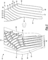
- FIG. 1 a view of a prior art two-part airfoil 10 is shown.
- the airfoil 10 has a suction side cover 15 and a pressure side 20.
- the suction side cover 15 is attached to a rib 25 depending from an inside 23 of the pressure side 20.
- the rib is attached to the suction side cover 15 by a bond 30 such as glue, welding or the like.
- the fan blade 110 has a suction side cover 115 and a pressure side 120.
- the pressure side 120 has an inner surface 127 from which ribs 125 extend towards the suction side cover 115.
- the ribs 125 have a longitudinal groove 128 formed therein.
- the suction side cover 115 has plurality of riblets 130 extending from an inner surface 131 thereof towards the pressure side 120.
- the groove may be machined or cast or forged into the ribs 125.
- groove 128 is shown with a rectangular contour and the riblets 130 also have a rectangular contour, other mating riblet 130 contours and groove 128 contours are contemplated herein providing such other contours provide increased gluing area and less motion between a riblet 130 and the groove 128.
- a glue 133 such as an epoxy or a urethane, may be used to join the ribs 125 and the riblets 130 together within the groove 128.
- glue 133 such as an epoxy or a urethane
- the amount of glue 133 used to join the suction side cover 115 and the pressure side 120 is increased by the amount of glue 133 placed on the sides 135 of the riblet, as compared to the prior art.
- the added glue 133 provides a concomitantly stronger bond between the suction side cover 115 and the suction side 120.
- the urethane glue may provide damping between the suction side cover 115 and the pressure side 120
- the effect of operative forces which may cause shear and tearing motion between the suction side cover 115 and the pressure side 120, are minimized because of a mechanical bond between the ribs 125 and the riblets 130 as the suction side cover 115 and pressure side 120 react to operation within an airstream.
- This mechanical advantage minimizes the effect of tear and shear force affecting suction side cover 115 and pressure side 120 of the fan blade 110.
- the inner surface 127 of the pressure side has an trench 140 (see Fig. 4 ) that approximates the sides 145 and the bottom 147 of the elbow-shape of the suction side cover 115.
- the trench is spaced from the leading edge 154 and the trailing edge 150 and the base 160 of the fan blade 110.
- the pressure side 115 has a first plurality 165 of ribs 125 extending from the trench 140 near the base 160 to the trench 140 adjacent the leading edge 154 of the trench and a second plurality 170 of ribs 125 extending from the trench 140 near the trailing edge 150 to the trench 140 near the leading edge 154.
- the suction side cover 115 has a set of corresponding riblets 130 that fit within the grooves of the first plurality 165 of ribs 125 and the second plurality 170 of ribs 125.
- the second plurality of ribs 170 extend from near the trailing 150 to near the leading edge 154 or towards the blade tip 173.
- the suction side cover 115 has a bead 180 extending along its outside edge 185 that mates with the trench 140.
- glue 133 is placed in the grooves 128 in the ribs 125 and the trench 140 and the riblets 130 are pressed into the grooves 128 and the bead 180 is pressed into the trench 140.
- a system designed according to an embodiment of this disclosure will not necessarily include all of the features shown in any one of the Figures or all of the portions schematically shown in the Figures.
- selected features of one example embodiment may be combined with selected features of other example embodiments.
- the riblets 130 may extend from the pressure side 115 and the ribs 125 may extend from the cover 120.
Landscapes
- Engineering & Computer Science (AREA)
- Mechanical Engineering (AREA)
- General Engineering & Computer Science (AREA)
- Aviation & Aerospace Engineering (AREA)
- Architecture (AREA)
- Structures Of Non-Positive Displacement Pumps (AREA)
Claims (14)
- Zweiteilige Ventilatorschaufel (110), umfassend:eine Saugseite (115), undeine Druckseite (120); wobeidie Druckseite (120) eines von einer Rippe (125) oder einem Riblet (130) aufweist, wobei sich die Rippe (125) oder das Riblet (130) von der Druckseite (120) in einer Richtung zu der Saugseite erstreckt und einstückig mit der Druckseite gebildet ist;dadurch gekennzeichnet, dass:die Saugseite (115) das andere von der Rippe (125) oder dem Riblet (130) aufweist, wobei sich das andere von der Rippe (125) oder dem Riblet (130) von der Saugseite (115) in einer Richtung zu der Druckseite erstreckt und einstückig mit der Saugseite gebildet ist;die Rippe (125) eine Nut (128) darin aufweist; unddas Riblet (130) in die Nut (128) passt.
- Zweiteilige Ventilatorschaufel nach Anspruch 1, ferner umfassend:
einen Klebstoff (135), der zwischen der Rippe (125) und dem Riblet (130) angeordnet ist. - Zweiteilige Ventilatorschaufel nach Anspruch 2, wobei der Klebstoff (135) ein Urethan-Klebstoff ist.
- Zweiteilige Ventilatorschaufel nach einem vorhergehenden Anspruch, wobei die Nut (128) länglich ist.
- Zweiteilige Ventilatorschaufel nach einem vorhergehenden Anspruch, wobei eine von der Saugseite (115) und der Druckseite (120) eine Rille (140) benachbart zu einem Außenprofil davon aufweist und wobei die andere von der Saugseite (115) und der Druckseite (120) eine Sicke (180) aufweist, die in die Rille (140) passt.
- Zweiteilige Ventilatorschaufel nach Anspruch 5, wobei die Rille (140) benachbart zu einer Vorderkante (154) und einer Basis (160) der Ventilatorschaufel (110) ist.
- Zweiteilige Ventilatorschaufel nach Anspruch 6, wobei sich eine Rippe (130) von der Rille (140) benachbart zu einer Basis der Ventilatorschaufel zu der Rille benachbart zu einer Vorderkante des Schaufelprofils erstreckt.
- Zweiteilige Ventilatorschaufel nach Anspruch 5, 6 oder 7, wobei die Rille (140) benachbart zu einer Vorderkante (154) und einer Hinterkante (150) der Ventilatorschaufel (110) ist.
- Zweiteilige Ventilatorschaufel nach Anspruch 8, wobei sich eine Rippe (130) von der Rille (140) benachbart zu der Vorderkante (154) zu der Rille (140) benachbart zu der Hinterkante (150) erstreckt.
- Zweiteilige Ventilatorschaufel nach einem der Ansprüche 5 bis 9, wobei sich die Rille (140) in der Druckseite (120) befindet.
- Zweiteilige Ventilatorschaufel nach einem vorhergehenden Anspruch, wobei sich die Rippe (130) von der Druckseite (120) erstreckt oder wobei sich das Riblet (130) von der Saugseite (115) erstreckt.
- Zweiteilige Ventilatorschaufel nach einem vorhergehenden Anspruch, wobei:die Nut (128) eine erste Kontur aufweist, unddas Riblet (130) eine zweite Kontur aufweist, die in die erste Kontur der Nut (128) passt.
- Zweiteilige Ventilatorschaufel nach Anspruch 11, wobei die erste Kontur und die zweite Kontur zusammenpassen.
- Zweiteilige Ventilatorschaufel nach Anspruch 12 oder 13, wobei die erste Kontur und die zweite Kontur rechteckig sind.
Applications Claiming Priority (1)
| Application Number | Priority Date | Filing Date | Title |
|---|---|---|---|
| US13/050,275 US20120237351A1 (en) | 2011-03-17 | 2011-03-17 | Retention for bonded hollow fan blade cover |
Publications (3)
| Publication Number | Publication Date |
|---|---|
| EP2500263A2 EP2500263A2 (de) | 2012-09-19 |
| EP2500263A3 EP2500263A3 (de) | 2015-11-04 |
| EP2500263B1 true EP2500263B1 (de) | 2020-01-22 |
Family
ID=45894204
Family Applications (1)
| Application Number | Title | Priority Date | Filing Date |
|---|---|---|---|
| EP12159600.1A Active EP2500263B1 (de) | 2011-03-17 | 2012-03-15 | Verbesserte Rückhaltung für geklebte hohle Ventilatorschaufelabdeckung |
Country Status (2)
| Country | Link |
|---|---|
| US (1) | US20120237351A1 (de) |
| EP (1) | EP2500263B1 (de) |
Families Citing this family (17)
| Publication number | Priority date | Publication date | Assignee | Title |
|---|---|---|---|---|
| FR2980514B1 (fr) * | 2011-09-23 | 2018-01-05 | Flakt Solyvent-Ventec | Pale de machine tournante a structure modulaire renforcee |
| US20130078103A1 (en) * | 2011-09-23 | 2013-03-28 | Christopher S. McKaveney | Hollow fan blade rib geometry |
| EP2900923B1 (de) * | 2012-09-25 | 2019-12-25 | United Technologies Corporation | Schaufelanordnung aus leitschaufeln mit unterschiedlicher geometrie nach geometrieklassen |
| WO2015058043A1 (en) | 2013-10-18 | 2015-04-23 | United Technologies Corporation | Multiple piece engine component |
| EP3074602B1 (de) * | 2013-11-26 | 2020-03-18 | United Technologies Corporation | Gebläseschaufel mit integrierter zusammengesetzter gebläseschaufelabdeckung |
| US10570917B2 (en) | 2016-08-01 | 2020-02-25 | United Technologies Corporation | Fan blade with composite cover |
| US20180038386A1 (en) * | 2016-08-08 | 2018-02-08 | United Technologies Corporation | Fan blade with composite cover |
| US11131314B2 (en) * | 2016-09-14 | 2021-09-28 | Raytheon Technologies Corporation | Fan blade with structural spar and integrated leading edge |
| US10450872B2 (en) * | 2016-11-08 | 2019-10-22 | Rolls-Royce Corporation | Undercut on airfoil coversheet support member |
| US10443613B2 (en) * | 2017-05-31 | 2019-10-15 | United Technologies Corporation | Hollow fan blade with structural ribs |
| US11389900B2 (en) | 2019-05-01 | 2022-07-19 | Raytheon Technologies Corporation | Welding method for hollow airfoils and intermediate body |
| US11225874B2 (en) | 2019-12-20 | 2022-01-18 | Raytheon Technologies Corporation | Turbine engine rotor blade with castellated tip surface |
| FR3105291B1 (fr) | 2019-12-20 | 2023-03-10 | Safran Aircraft Engines | Aube de soufflante ou d’helice pour une turbomachine d’aeronef et son procede de fabrication |
| US11913352B2 (en) * | 2021-12-08 | 2024-02-27 | General Electric Company | Cover plate connections for a hollow fan blade |
| US11873738B2 (en) * | 2021-12-23 | 2024-01-16 | General Electric Company | Integrated stator-fan frame assembly |
| CN115489719A (zh) * | 2022-10-28 | 2022-12-20 | 四川腾盾科技有限公司 | 一种飞机机翼舵面结构 |
| US11867084B1 (en) * | 2022-12-20 | 2024-01-09 | Rtx Corporation | Hollow airfoil construction using cover subassembly |
Citations (1)
| Publication number | Priority date | Publication date | Assignee | Title |
|---|---|---|---|---|
| WO2005098241A1 (en) * | 2004-03-31 | 2005-10-20 | Remmele Engineering, Inc. | Connection mechanism and method |
Family Cites Families (16)
| Publication number | Priority date | Publication date | Assignee | Title |
|---|---|---|---|---|
| US2954208A (en) * | 1953-01-09 | 1960-09-27 | Gen Motors Corp | Air foil section |
| US5487930A (en) * | 1991-10-03 | 1996-01-30 | Tolo, Inc. | Three structure structural element with interlocking ribbing |
| US5269058A (en) * | 1992-12-16 | 1993-12-14 | General Electric Company | Design and processing method for manufacturing hollow airfoils |
| US5498137A (en) * | 1995-02-17 | 1996-03-12 | United Technologies Corporation | Turbine engine rotor blade vibration damping device |
| US5849393A (en) * | 1997-04-17 | 1998-12-15 | Mcdonnell Douglas Corporation | Structural element and method of making |
| US20030069321A1 (en) * | 2001-10-05 | 2003-04-10 | Lin Wendy Wen-Ling | High modulus, impact resistant foams for structural components |
| US7238409B1 (en) * | 2002-05-23 | 2007-07-03 | Rohr, Inc. | Structural element with rib-receiving member |
| US7037568B1 (en) * | 2003-07-15 | 2006-05-02 | Rogers Terry W | Joining member for mechanically joining a skin to a supporting rib |
| US7189064B2 (en) * | 2004-05-14 | 2007-03-13 | General Electric Company | Friction stir welded hollow airfoils and method therefor |
| US7393488B2 (en) * | 2005-05-25 | 2008-07-01 | The Boeing Company | Methods of joining structures and joints formed thereby |
| US7398586B2 (en) * | 2005-11-01 | 2008-07-15 | The Boeing Company | Methods and systems for manufacturing a family of aircraft wings and other composite structures |
| US7980817B2 (en) * | 2007-04-16 | 2011-07-19 | United Technologies Corporation | Gas turbine engine vane |
| US8083489B2 (en) * | 2009-04-16 | 2011-12-27 | United Technologies Corporation | Hybrid structure fan blade |
| US8585368B2 (en) * | 2009-04-16 | 2013-11-19 | United Technologies Corporation | Hybrid structure airfoil |
| US8235670B2 (en) * | 2009-06-17 | 2012-08-07 | Siemens Energy, Inc. | Interlocked CMC airfoil |
| US8851856B2 (en) * | 2010-08-06 | 2014-10-07 | Rohr, Inc. | Rotor blade comprising structural elements |
-
2011
- 2011-03-17 US US13/050,275 patent/US20120237351A1/en not_active Abandoned
-
2012
- 2012-03-15 EP EP12159600.1A patent/EP2500263B1/de active Active
Patent Citations (1)
| Publication number | Priority date | Publication date | Assignee | Title |
|---|---|---|---|---|
| WO2005098241A1 (en) * | 2004-03-31 | 2005-10-20 | Remmele Engineering, Inc. | Connection mechanism and method |
Also Published As
| Publication number | Publication date |
|---|---|
| EP2500263A3 (de) | 2015-11-04 |
| US20120237351A1 (en) | 2012-09-20 |
| EP2500263A2 (de) | 2012-09-19 |
Similar Documents
| Publication | Publication Date | Title |
|---|---|---|
| EP2500263B1 (de) | Verbesserte Rückhaltung für geklebte hohle Ventilatorschaufelabdeckung | |
| US8251664B2 (en) | Fan blade for a gas-turbine engine | |
| EP2811143B1 (de) | Gebläserotorschaufel eines flugzeugtriebwerks | |
| EP2243929B1 (de) | Fanschaufel mit hybridstruktur | |
| US7762785B2 (en) | Main rotor blade with integral tip section | |
| EP3063375B1 (de) | Bläserschaufel mit verbundstoffsegmenten | |
| EP3336308A2 (de) | Gebläseschaufel mit strukturholm und integrierter vorderkante | |
| EP3216693A1 (de) | Aerodynamische fläche eines flugzeugs mit abnehmbarer vorderkante | |
| CN105849423A (zh) | 异种材料的接合结构 | |
| EP2811144A1 (de) | Gebläserotorschaufel eines flugzeugtriebwerks | |
| CN105736462B (zh) | 空心叶片以及航空发动机 | |
| EP2607628A3 (de) | Schaufelblätter mit nachgiebiger Spitze | |
| US20180274375A1 (en) | Blade comprising a folded leading edge shield and method of manufacturing the blade | |
| US20130333350A1 (en) | Airfoil including adhesively bonded shroud | |
| EP3165465B1 (de) | Behälterhaken für verbundstoff-lüftergehäuse | |
| US20180100516A1 (en) | Vane comprising an assembled platform and blade | |
| US10351229B2 (en) | Metallic dimpled doubler | |
| EP2641830A2 (de) | Dichtungsanordnung für einen Flugzeugflügel | |
| US8152465B2 (en) | Rotor blade for a rotor airplane | |
| US9976430B2 (en) | Blade in fan, and fan | |
| US20110147525A1 (en) | Sealing of airflow between a wing and a fuselage | |
| EP2573321B1 (de) | Gebläseschaufel | |
| WO2010037964A3 (fr) | Assemblage de panneaux pour fuselage d'aeronef | |
| EP2955326B1 (de) | Gasturbinenschaufel mit einem erdungselement | |
| US20050247821A1 (en) | Transition shim between structure for fastening a wing to a fuselage of an aircraft, and aircraft having such a shim |
Legal Events
| Date | Code | Title | Description |
|---|---|---|---|
| PUAI | Public reference made under article 153(3) epc to a published international application that has entered the european phase |
Free format text: ORIGINAL CODE: 0009012 |
|
| AK | Designated contracting states |
Kind code of ref document: A2 Designated state(s): AL AT BE BG CH CY CZ DE DK EE ES FI FR GB GR HR HU IE IS IT LI LT LU LV MC MK MT NL NO PL PT RO RS SE SI SK SM TR |
|
| AX | Request for extension of the european patent |
Extension state: BA ME |
|
| PUAL | Search report despatched |
Free format text: ORIGINAL CODE: 0009013 |
|
| AK | Designated contracting states |
Kind code of ref document: A3 Designated state(s): AL AT BE BG CH CY CZ DE DK EE ES FI FR GB GR HR HU IE IS IT LI LT LU LV MC MK MT NL NO PL PT RO RS SE SI SK SM TR |
|
| AX | Request for extension of the european patent |
Extension state: BA ME |
|
| RIC1 | Information provided on ipc code assigned before grant |
Ipc: B64C 11/24 20060101AFI20150930BHEP |
|
| 17P | Request for examination filed |
Effective date: 20160504 |
|
| RBV | Designated contracting states (corrected) |
Designated state(s): AL AT BE BG CH CY CZ DE DK EE ES FI FR GB GR HR HU IE IS IT LI LT LU LV MC MK MT NL NO PL PT RO RS SE SI SK SM TR |
|
| RAP1 | Party data changed (applicant data changed or rights of an application transferred) |
Owner name: UNITED TECHNOLOGIES CORPORATION |
|
| STAA | Information on the status of an ep patent application or granted ep patent |
Free format text: STATUS: EXAMINATION IS IN PROGRESS |
|
| 17Q | First examination report despatched |
Effective date: 20180525 |
|
| GRAP | Despatch of communication of intention to grant a patent |
Free format text: ORIGINAL CODE: EPIDOSNIGR1 |
|
| STAA | Information on the status of an ep patent application or granted ep patent |
Free format text: STATUS: GRANT OF PATENT IS INTENDED |
|
| INTG | Intention to grant announced |
Effective date: 20190809 |
|
| GRAS | Grant fee paid |
Free format text: ORIGINAL CODE: EPIDOSNIGR3 |
|
| GRAA | (expected) grant |
Free format text: ORIGINAL CODE: 0009210 |
|
| STAA | Information on the status of an ep patent application or granted ep patent |
Free format text: STATUS: THE PATENT HAS BEEN GRANTED |
|
| AK | Designated contracting states |
Kind code of ref document: B1 Designated state(s): AL AT BE BG CH CY CZ DE DK EE ES FI FR GB GR HR HU IE IS IT LI LT LU LV MC MK MT NL NO PL PT RO RS SE SI SK SM TR |
|
| REG | Reference to a national code |
Ref country code: GB Ref legal event code: FG4D |
|
| REG | Reference to a national code |
Ref country code: CH Ref legal event code: EP |
|
| REG | Reference to a national code |
Ref country code: AT Ref legal event code: REF Ref document number: 1226759 Country of ref document: AT Kind code of ref document: T Effective date: 20200215 |
|
| REG | Reference to a national code |
Ref country code: IE Ref legal event code: FG4D |
|
| REG | Reference to a national code |
Ref country code: DE Ref legal event code: R096 Ref document number: 602012067360 Country of ref document: DE |
|
| REG | Reference to a national code |
Ref country code: NL Ref legal event code: MP Effective date: 20200122 |
|
| REG | Reference to a national code |
Ref country code: LT Ref legal event code: MG4D |
|
| PG25 | Lapsed in a contracting state [announced via postgrant information from national office to epo] |
Ref country code: NL Free format text: LAPSE BECAUSE OF FAILURE TO SUBMIT A TRANSLATION OF THE DESCRIPTION OR TO PAY THE FEE WITHIN THE PRESCRIBED TIME-LIMIT Effective date: 20200122 Ref country code: RS Free format text: LAPSE BECAUSE OF FAILURE TO SUBMIT A TRANSLATION OF THE DESCRIPTION OR TO PAY THE FEE WITHIN THE PRESCRIBED TIME-LIMIT Effective date: 20200122 Ref country code: PT Free format text: LAPSE BECAUSE OF FAILURE TO SUBMIT A TRANSLATION OF THE DESCRIPTION OR TO PAY THE FEE WITHIN THE PRESCRIBED TIME-LIMIT Effective date: 20200614 Ref country code: FI Free format text: LAPSE BECAUSE OF FAILURE TO SUBMIT A TRANSLATION OF THE DESCRIPTION OR TO PAY THE FEE WITHIN THE PRESCRIBED TIME-LIMIT Effective date: 20200122 Ref country code: NO Free format text: LAPSE BECAUSE OF FAILURE TO SUBMIT A TRANSLATION OF THE DESCRIPTION OR TO PAY THE FEE WITHIN THE PRESCRIBED TIME-LIMIT Effective date: 20200422 |
|
| PG25 | Lapsed in a contracting state [announced via postgrant information from national office to epo] |
Ref country code: SE Free format text: LAPSE BECAUSE OF FAILURE TO SUBMIT A TRANSLATION OF THE DESCRIPTION OR TO PAY THE FEE WITHIN THE PRESCRIBED TIME-LIMIT Effective date: 20200122 Ref country code: HR Free format text: LAPSE BECAUSE OF FAILURE TO SUBMIT A TRANSLATION OF THE DESCRIPTION OR TO PAY THE FEE WITHIN THE PRESCRIBED TIME-LIMIT Effective date: 20200122 Ref country code: IS Free format text: LAPSE BECAUSE OF FAILURE TO SUBMIT A TRANSLATION OF THE DESCRIPTION OR TO PAY THE FEE WITHIN THE PRESCRIBED TIME-LIMIT Effective date: 20200522 Ref country code: BG Free format text: LAPSE BECAUSE OF FAILURE TO SUBMIT A TRANSLATION OF THE DESCRIPTION OR TO PAY THE FEE WITHIN THE PRESCRIBED TIME-LIMIT Effective date: 20200422 Ref country code: GR Free format text: LAPSE BECAUSE OF FAILURE TO SUBMIT A TRANSLATION OF THE DESCRIPTION OR TO PAY THE FEE WITHIN THE PRESCRIBED TIME-LIMIT Effective date: 20200423 Ref country code: LV Free format text: LAPSE BECAUSE OF FAILURE TO SUBMIT A TRANSLATION OF THE DESCRIPTION OR TO PAY THE FEE WITHIN THE PRESCRIBED TIME-LIMIT Effective date: 20200122 |
|
| REG | Reference to a national code |
Ref country code: DE Ref legal event code: R097 Ref document number: 602012067360 Country of ref document: DE |
|
| PG25 | Lapsed in a contracting state [announced via postgrant information from national office to epo] |
Ref country code: RO Free format text: LAPSE BECAUSE OF FAILURE TO SUBMIT A TRANSLATION OF THE DESCRIPTION OR TO PAY THE FEE WITHIN THE PRESCRIBED TIME-LIMIT Effective date: 20200122 Ref country code: CZ Free format text: LAPSE BECAUSE OF FAILURE TO SUBMIT A TRANSLATION OF THE DESCRIPTION OR TO PAY THE FEE WITHIN THE PRESCRIBED TIME-LIMIT Effective date: 20200122 Ref country code: SK Free format text: LAPSE BECAUSE OF FAILURE TO SUBMIT A TRANSLATION OF THE DESCRIPTION OR TO PAY THE FEE WITHIN THE PRESCRIBED TIME-LIMIT Effective date: 20200122 Ref country code: SM Free format text: LAPSE BECAUSE OF FAILURE TO SUBMIT A TRANSLATION OF THE DESCRIPTION OR TO PAY THE FEE WITHIN THE PRESCRIBED TIME-LIMIT Effective date: 20200122 Ref country code: EE Free format text: LAPSE BECAUSE OF FAILURE TO SUBMIT A TRANSLATION OF THE DESCRIPTION OR TO PAY THE FEE WITHIN THE PRESCRIBED TIME-LIMIT Effective date: 20200122 Ref country code: DK Free format text: LAPSE BECAUSE OF FAILURE TO SUBMIT A TRANSLATION OF THE DESCRIPTION OR TO PAY THE FEE WITHIN THE PRESCRIBED TIME-LIMIT Effective date: 20200122 Ref country code: MC Free format text: LAPSE BECAUSE OF FAILURE TO SUBMIT A TRANSLATION OF THE DESCRIPTION OR TO PAY THE FEE WITHIN THE PRESCRIBED TIME-LIMIT Effective date: 20200122 Ref country code: LT Free format text: LAPSE BECAUSE OF FAILURE TO SUBMIT A TRANSLATION OF THE DESCRIPTION OR TO PAY THE FEE WITHIN THE PRESCRIBED TIME-LIMIT Effective date: 20200122 Ref country code: ES Free format text: LAPSE BECAUSE OF FAILURE TO SUBMIT A TRANSLATION OF THE DESCRIPTION OR TO PAY THE FEE WITHIN THE PRESCRIBED TIME-LIMIT Effective date: 20200122 |
|
| REG | Reference to a national code |
Ref country code: CH Ref legal event code: PL |
|
| REG | Reference to a national code |
Ref country code: AT Ref legal event code: MK05 Ref document number: 1226759 Country of ref document: AT Kind code of ref document: T Effective date: 20200122 |
|
| PLBE | No opposition filed within time limit |
Free format text: ORIGINAL CODE: 0009261 |
|
| STAA | Information on the status of an ep patent application or granted ep patent |
Free format text: STATUS: NO OPPOSITION FILED WITHIN TIME LIMIT |
|
| REG | Reference to a national code |
Ref country code: BE Ref legal event code: MM Effective date: 20200331 |
|
| 26N | No opposition filed |
Effective date: 20201023 |
|
| PG25 | Lapsed in a contracting state [announced via postgrant information from national office to epo] |
Ref country code: LU Free format text: LAPSE BECAUSE OF NON-PAYMENT OF DUE FEES Effective date: 20200315 |
|
| PG25 | Lapsed in a contracting state [announced via postgrant information from national office to epo] |
Ref country code: CH Free format text: LAPSE BECAUSE OF NON-PAYMENT OF DUE FEES Effective date: 20200331 Ref country code: IE Free format text: LAPSE BECAUSE OF NON-PAYMENT OF DUE FEES Effective date: 20200315 Ref country code: AT Free format text: LAPSE BECAUSE OF FAILURE TO SUBMIT A TRANSLATION OF THE DESCRIPTION OR TO PAY THE FEE WITHIN THE PRESCRIBED TIME-LIMIT Effective date: 20200122 Ref country code: IT Free format text: LAPSE BECAUSE OF FAILURE TO SUBMIT A TRANSLATION OF THE DESCRIPTION OR TO PAY THE FEE WITHIN THE PRESCRIBED TIME-LIMIT Effective date: 20200122 Ref country code: LI Free format text: LAPSE BECAUSE OF NON-PAYMENT OF DUE FEES Effective date: 20200331 |
|
| PG25 | Lapsed in a contracting state [announced via postgrant information from national office to epo] |
Ref country code: BE Free format text: LAPSE BECAUSE OF NON-PAYMENT OF DUE FEES Effective date: 20200331 Ref country code: PL Free format text: LAPSE BECAUSE OF FAILURE TO SUBMIT A TRANSLATION OF THE DESCRIPTION OR TO PAY THE FEE WITHIN THE PRESCRIBED TIME-LIMIT Effective date: 20200122 Ref country code: SI Free format text: LAPSE BECAUSE OF FAILURE TO SUBMIT A TRANSLATION OF THE DESCRIPTION OR TO PAY THE FEE WITHIN THE PRESCRIBED TIME-LIMIT Effective date: 20200122 |
|
| PG25 | Lapsed in a contracting state [announced via postgrant information from national office to epo] |
Ref country code: TR Free format text: LAPSE BECAUSE OF FAILURE TO SUBMIT A TRANSLATION OF THE DESCRIPTION OR TO PAY THE FEE WITHIN THE PRESCRIBED TIME-LIMIT Effective date: 20200122 Ref country code: MT Free format text: LAPSE BECAUSE OF FAILURE TO SUBMIT A TRANSLATION OF THE DESCRIPTION OR TO PAY THE FEE WITHIN THE PRESCRIBED TIME-LIMIT Effective date: 20200122 Ref country code: CY Free format text: LAPSE BECAUSE OF FAILURE TO SUBMIT A TRANSLATION OF THE DESCRIPTION OR TO PAY THE FEE WITHIN THE PRESCRIBED TIME-LIMIT Effective date: 20200122 |
|
| PG25 | Lapsed in a contracting state [announced via postgrant information from national office to epo] |
Ref country code: MK Free format text: LAPSE BECAUSE OF FAILURE TO SUBMIT A TRANSLATION OF THE DESCRIPTION OR TO PAY THE FEE WITHIN THE PRESCRIBED TIME-LIMIT Effective date: 20200122 Ref country code: AL Free format text: LAPSE BECAUSE OF FAILURE TO SUBMIT A TRANSLATION OF THE DESCRIPTION OR TO PAY THE FEE WITHIN THE PRESCRIBED TIME-LIMIT Effective date: 20200122 |
|
| REG | Reference to a national code |
Ref country code: DE Ref legal event code: R081 Ref document number: 602012067360 Country of ref document: DE Owner name: RAYTHEON TECHNOLOGIES CORPORATION (N.D.GES.D.S, US Free format text: FORMER OWNER: UNITED TECHNOLOGIES CORPORATION, FARMINGTON, CONN., US Ref country code: DE Ref legal event code: R081 Ref document number: 602012067360 Country of ref document: DE Owner name: RTX CORPORATION (N.D.GES.D. STAATES DELAWARE),, US Free format text: FORMER OWNER: UNITED TECHNOLOGIES CORPORATION, FARMINGTON, CONN., US |
|
| P01 | Opt-out of the competence of the unified patent court (upc) registered |
Effective date: 20230520 |
|
| REG | Reference to a national code |
Ref country code: DE Ref legal event code: R081 Ref document number: 602012067360 Country of ref document: DE Owner name: RTX CORPORATION (N.D.GES.D. STAATES DELAWARE),, US Free format text: FORMER OWNER: RAYTHEON TECHNOLOGIES CORPORATION (N.D.GES.D.STAATES DELAWARE), ARLINGTON, VA, US |
|
| PGFP | Annual fee paid to national office [announced via postgrant information from national office to epo] |
Ref country code: GB Payment date: 20260220 Year of fee payment: 15 |
|
| PGFP | Annual fee paid to national office [announced via postgrant information from national office to epo] |
Ref country code: DE Payment date: 20260219 Year of fee payment: 15 |
|
| PGFP | Annual fee paid to national office [announced via postgrant information from national office to epo] |
Ref country code: FR Payment date: 20260220 Year of fee payment: 15 |