EP2500216A1 - Method and device for images for a driver assistance system - Google Patents
Method and device for images for a driver assistance system Download PDFInfo
- Publication number
- EP2500216A1 EP2500216A1 EP12001048A EP12001048A EP2500216A1 EP 2500216 A1 EP2500216 A1 EP 2500216A1 EP 12001048 A EP12001048 A EP 12001048A EP 12001048 A EP12001048 A EP 12001048A EP 2500216 A1 EP2500216 A1 EP 2500216A1
- Authority
- EP
- European Patent Office
- Prior art keywords
- vehicle
- image
- driver assistance
- assistance system
- imaging driver
- Prior art date
- Legal status (The legal status is an assumption and is not a legal conclusion. Google has not performed a legal analysis and makes no representation as to the accuracy of the status listed.)
- Granted
Links
- 238000000034 method Methods 0.000 title claims abstract description 11
- 238000003384 imaging method Methods 0.000 claims abstract description 10
- 230000003287 optical effect Effects 0.000 claims description 2
- 235000004522 Pentaglottis sempervirens Nutrition 0.000 description 4
- 238000001514 detection method Methods 0.000 description 4
- 230000007704 transition Effects 0.000 description 3
- 230000009466 transformation Effects 0.000 description 2
- 240000004050 Pentaglottis sempervirens Species 0.000 description 1
- 230000006872 improvement Effects 0.000 description 1
- 239000003550 marker Substances 0.000 description 1
- 238000002156 mixing Methods 0.000 description 1
- 230000008569 process Effects 0.000 description 1
- 238000001454 recorded image Methods 0.000 description 1
- 230000002123 temporal effect Effects 0.000 description 1
Images


Classifications
-
- B—PERFORMING OPERATIONS; TRANSPORTING
- B60—VEHICLES IN GENERAL
- B60R—VEHICLES, VEHICLE FITTINGS, OR VEHICLE PARTS, NOT OTHERWISE PROVIDED FOR
- B60R1/00—Optical viewing arrangements; Real-time viewing arrangements for drivers or passengers using optical image capturing systems, e.g. cameras or video systems specially adapted for use in or on vehicles
- B60R1/20—Real-time viewing arrangements for drivers or passengers using optical image capturing systems, e.g. cameras or video systems specially adapted for use in or on vehicles
- B60R1/22—Real-time viewing arrangements for drivers or passengers using optical image capturing systems, e.g. cameras or video systems specially adapted for use in or on vehicles for viewing an area outside the vehicle, e.g. the exterior of the vehicle
- B60R1/23—Real-time viewing arrangements for drivers or passengers using optical image capturing systems, e.g. cameras or video systems specially adapted for use in or on vehicles for viewing an area outside the vehicle, e.g. the exterior of the vehicle with a predetermined field of view
- B60R1/27—Real-time viewing arrangements for drivers or passengers using optical image capturing systems, e.g. cameras or video systems specially adapted for use in or on vehicles for viewing an area outside the vehicle, e.g. the exterior of the vehicle with a predetermined field of view providing all-round vision, e.g. using omnidirectional cameras
-
- B—PERFORMING OPERATIONS; TRANSPORTING
- B60—VEHICLES IN GENERAL
- B60R—VEHICLES, VEHICLE FITTINGS, OR VEHICLE PARTS, NOT OTHERWISE PROVIDED FOR
- B60R2300/00—Details of viewing arrangements using cameras and displays, specially adapted for use in a vehicle
- B60R2300/10—Details of viewing arrangements using cameras and displays, specially adapted for use in a vehicle characterised by the type of camera system used
- B60R2300/105—Details of viewing arrangements using cameras and displays, specially adapted for use in a vehicle characterised by the type of camera system used using multiple cameras
-
- B—PERFORMING OPERATIONS; TRANSPORTING
- B60—VEHICLES IN GENERAL
- B60R—VEHICLES, VEHICLE FITTINGS, OR VEHICLE PARTS, NOT OTHERWISE PROVIDED FOR
- B60R2300/00—Details of viewing arrangements using cameras and displays, specially adapted for use in a vehicle
- B60R2300/30—Details of viewing arrangements using cameras and displays, specially adapted for use in a vehicle characterised by the type of image processing
- B60R2300/302—Details of viewing arrangements using cameras and displays, specially adapted for use in a vehicle characterised by the type of image processing combining image information with GPS information or vehicle data, e.g. vehicle speed, gyro, steering angle data
-
- B—PERFORMING OPERATIONS; TRANSPORTING
- B60—VEHICLES IN GENERAL
- B60R—VEHICLES, VEHICLE FITTINGS, OR VEHICLE PARTS, NOT OTHERWISE PROVIDED FOR
- B60R2300/00—Details of viewing arrangements using cameras and displays, specially adapted for use in a vehicle
- B60R2300/30—Details of viewing arrangements using cameras and displays, specially adapted for use in a vehicle characterised by the type of image processing
- B60R2300/303—Details of viewing arrangements using cameras and displays, specially adapted for use in a vehicle characterised by the type of image processing using joined images, e.g. multiple camera images
-
- B—PERFORMING OPERATIONS; TRANSPORTING
- B60—VEHICLES IN GENERAL
- B60R—VEHICLES, VEHICLE FITTINGS, OR VEHICLE PARTS, NOT OTHERWISE PROVIDED FOR
- B60R2300/00—Details of viewing arrangements using cameras and displays, specially adapted for use in a vehicle
- B60R2300/60—Details of viewing arrangements using cameras and displays, specially adapted for use in a vehicle characterised by monitoring and displaying vehicle exterior scenes from a transformed perspective
- B60R2300/602—Details of viewing arrangements using cameras and displays, specially adapted for use in a vehicle characterised by monitoring and displaying vehicle exterior scenes from a transformed perspective with an adjustable viewpoint
- B60R2300/605—Details of viewing arrangements using cameras and displays, specially adapted for use in a vehicle characterised by monitoring and displaying vehicle exterior scenes from a transformed perspective with an adjustable viewpoint the adjustment being automatic
-
- B—PERFORMING OPERATIONS; TRANSPORTING
- B60—VEHICLES IN GENERAL
- B60R—VEHICLES, VEHICLE FITTINGS, OR VEHICLE PARTS, NOT OTHERWISE PROVIDED FOR
- B60R2300/00—Details of viewing arrangements using cameras and displays, specially adapted for use in a vehicle
- B60R2300/60—Details of viewing arrangements using cameras and displays, specially adapted for use in a vehicle characterised by monitoring and displaying vehicle exterior scenes from a transformed perspective
- B60R2300/607—Details of viewing arrangements using cameras and displays, specially adapted for use in a vehicle characterised by monitoring and displaying vehicle exterior scenes from a transformed perspective from a bird's eye viewpoint
-
- B—PERFORMING OPERATIONS; TRANSPORTING
- B60—VEHICLES IN GENERAL
- B60R—VEHICLES, VEHICLE FITTINGS, OR VEHICLE PARTS, NOT OTHERWISE PROVIDED FOR
- B60R2300/00—Details of viewing arrangements using cameras and displays, specially adapted for use in a vehicle
- B60R2300/70—Details of viewing arrangements using cameras and displays, specially adapted for use in a vehicle characterised by an event-triggered choice to display a specific image among a selection of captured images
Definitions
- the reversing camera is usually attached to the rear of the vehicle, such as in DE 10342971 A1 described.
- the camera image is usually displayed without further processing or with parking aid lines.
- One of the disadvantages of the known methods consists in the unsatisfactory detail resolution of the display unit, since in a reverse drive always the entire detection range of the rear view camera is displayed. Since the display units are quite small in the vehicle due to the limited space, small objects can be displayed only insufficient.
- the invention is therefore based on the object to improve the resolution of the display unit when driving back.
- the displayed image section of a reversing camera is to be dynamically changed on the basis of the calculated direction of movement of the vehicle.
- An essential feature of the invention is that the image processing unit receives information about the current steering angle of the vehicle and adapts the image detail, which is displayed on the display unit, dynamically to the steering angle.
- the illustrated image section represents the image area in an enlarged view, to which the vehicle moves according to the calculated movement direction to or away.
- At least one steering angle information is used to calculate the direction of movement whereby the accuracy of the calculation can be improved by additional parameters such as speed and vehicle geometry.
- an image detail calculation unit is used. It is also proposed to use a curved virtual projection surface, which is preferably aligned perpendicular to the road surface. This improves the clarity.
- one or more camera images are arranged according to their geometric arrangement on the vehicle on a virtual projection surface.
- the invention also contemplates that distortion correction be useful for wide-angle optics.
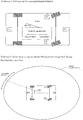
- FIG. 1 is shown a possible arrangement of the cameras on the vehicle.
- 4 cameras are used, but the described method can generally be implemented with 1 to N cameras. If too few cameras are used, in certain situations no image information is available and the corresponding image area is filled, for example, with black or a warning mark.
- camera 1 (K1) are installed, for example, in the grille and camera 4 (K4) in the tailgate.
- Camera 2 (K2) on the left side and camera 3 (K3) on the right are each mounted at the level of the vehicle outside mirrors.
- the combination of mounting position and optics of the cameras enables a 360 ° view around the vehicle.
- the vertical detection range of the cameras is designed so that the entire area is taken up from the lower edge of the vehicle frame to the horizon.
- the horizontal detection range of each camera is about 180 °, so the coverage areas of the cameras partially overlap.
- FIG. 2 and 3 The principle of image generation is in FIG. 2 and 3 shown.
- a three-dimensional model of a virtual projection screen is used.
- this projection surface is approximately in the form of a vertical cylinder of elliptical cross-section enclosing the vehicle at a defined distance.
- the projection surface is divided into 4 parts whose image contents are each textured with the image data of the corresponding camera.
- a back projection of the recorded image onto the virtual projection plane is calculated in each case.
- vertical objects are displayed vertically and with few distortions.
- a section of this virtual projection screen is displayed, which is shown in FIG FIG. 2 is shown as an example for a reverse drive to the left.
- the area of the virtual projection area that is displayed on the display unit is selected.
- the displayed image section is dynamically adjusted so that the user sees at any time the area around the vehicle to which the vehicle is moving or from which it is moving. This results in a representation of the vehicle environment which is understandable and easily comprehensible for the viewer.
- the generation of the described image view is done with the in FIG. 4 illustrated image processing system.
- the image data 43 of at least one camera are fed to the image processing unit.
- the image processing unit also receives at least one steering angle information 40 from the vehicle bus.
- the direction calculation unit calculates, from at least one steering angle information 40, a movement direction information 41 for the Vehicle.
- the movement direction information consists of at least one angle alpha and direction information ( FIGS. 5 and 6 ).
- the angle alpha describes the deviation of the direction of movement from the straight-ahead direction of the vehicle as in FIGS. 5 and 6 shown. To increase the accuracy of the angle calculation, further information such as the speed and the vehicle geometry can be included in the calculation.
- the direction information describes the current direction of travel of the vehicle and can assume the states "forward travel” and "reverse travel".
- the direction information is constantly set to the value "reverse drive” and the input unit is omitted.
- the direction information is determined, for example, from the shift lever position or the camera images.
- the image detail calculation unit determines the area of the virtual projection area that is to be displayed by the display unit. It uses the movement direction information 41 as well as the known geometry data of the vehicle and the virtual projection area to calculate an image detail information 42.
- the image detail information is calculated such that the displayed image detail indicates the environment to which the vehicle is moving to or from.
- the method is exemplary of a reverse drive with steering left in FIG. 6 illustrated.
- the image detail calculation unit also processes mode information that the driver can set via an input unit.
- the input unit can as in FIG. 4 shown connected directly to the image processing unit, the mode information can also be provided via the vehicle bus.
- the execution of the input unit can be done by way of example by switches or voice input.
- the direction information is constantly set to "reverse".
- the image section calculation unit always determines the image section in the rear region of the vehicle to which it is moving in a reverse movement and from which it moves on in a forward motion. This mode is particularly helpful when reversing parking.
- the direction of travel is constantly set to "forward travel".
- the image section calculation unit always determines the image section in the front region of the vehicle to which it is moving in a forward movement and from which it moves on in a reverse travel. This mode is particularly helpful when parking.
- the direction information is used by the movement direction unit to automatically switch between the front and rear views. If the image section calculation unit receives a "reverse drive” signal from the direction calculation unit, an image section in the rear area of the vehicle to which the vehicle is moving backwards is selected. If the image detail calculation unit receives a "forward drive” signal, an image detail is selected in the front region of the vehicle to which the vehicle is moving forward. In this operating mode, the driver is always shown exactly the image area to which the vehicle is currently moving.
- At least one of the three modes of operation is implemented.
- the image transformation unit receives the camera data 43 and the image detail information 42, and performs the calculations for generating the image output information 44.
- the image transformation unit receives from each camera a temporal sequence of images and calculates in each case from the temporally associated N images, the representation on the virtual screen according to the Figures 2 and 3 , In a second step, the image area to be displayed is corresponding to Image detail information 42 is extracted and the image information 44 is output to the display unit.
- a special feature of the invention is the use of multiple camera images to generate the image information. As in FIG. 2 it may occur at certain steering angles that the image information of a camera is not sufficient to generate the image view from a camera image.
- the innovative image generation method displays image sections of two cameras next to each other according to their geometric arrangement on the vehicle. The ratio of the two image sections shown dynamically shifts according to the current steering angle, so that the user always obtains a meaningful image of the surroundings.
- the transition between two cameras can be done by a transition blending, or by a hard transition with an optional marker.
Abstract
Description
Im Bereich der Fahrzeugtechnik werden vermehrt Kameras eingesetzt um den Fahrer in verschiedenen Fahrsituationen zu unterstützen. In der Klasse der bildgebenden Systeme haben sich bereits Rückfahrkameras etabliert, die insbesondere in Einparksituationen das Unfallrisiko reduziert.In the field of vehicle technology, more and more cameras are used to assist the driver in different driving situations. Back-up cameras have already become established in the class of imaging systems, which reduces the risk of accidents, especially in parking situations.
Die Rückfahrkamera wird in der Regel am Heck des Fahrzeugs angebracht, wie beispielsweise in
Sowohl im PKW- als auch im Nutzfahrzeugbereich werden inzwischen Rundumsichtsysteme verwendet, die vier oder mehr Kameras mit großem Erfassungsbereich verwenden um das Umfeld des Fahrzeugs aufzunehmen. Um diese Funktion zu erfüllen werden die Kameras mit Weitwinkelobjektiven oder speziellen Spiegeln ausgestattet, wobei die die Rohbilder in eine für den Fahrer brauchbare Darstellung transformiert werden müssen. Eine verbreitete Darstellungsform stellt die virtuelle Draufsicht in der Art einer Vogelperspektive dar, die dem Fahrer eine gute Orientierung im Nahbereich des Fahrzeugs ermöglicht wie beispielsweise in
Da die Anzeigeeinheiten im Fahrzeug recht klein sind, muss bei der Darstellung der Vogelperspektive ein Kompromiss zwischen der Größe des um das Fahrzeug dargestellten Bereichs und der Bildauflösung getroffen werden. Wenn der dargestellte Bereich zu groß gewählt wird, können Details wegen der unzureichenden Auflösung nicht mehr angezeigt werden. Bei Pkws wird häufig nur ein Bereich von ca. 2 bis 3 Metern um das Fahrzeug dargestellt.Both in the passenger car and in the commercial vehicle sector, all-round vision systems are now being used, which use four or more cameras with a large detection range to record the surroundings of the vehicle. To fulfill this function, the cameras are equipped with wide-angle lenses or special mirrors, whereby the raw images must be transformed into a representation that is useful for the driver. A common form of presentation is the virtual top view in the manner of a bird's-eye view, which allows the driver a good orientation in the vicinity of the vehicle such as in
Since the display units in the vehicle are quite small, in the representation of the bird's eye view, a compromise between the size of the area around the vehicle and the image resolution must be made. If the displayed area is too large, details may not be displayed due to insufficient resolution. For cars, often only a range of about 2 to 3 meters is shown around the vehicle.
Der Nachteil dieser Darstellungsform besteht darin, dass entfernte Objekte überhaupt nicht angezeigt werden, obwohl sie von den Kameras erfasst wurden. Daher hat der Benutzer Probleme sich in der Umgebung zu orientieren, beispielsweise wenn bei einer Rückwärtsfahrt ein 5 m entferntes Garagentor angefahren werden muss, welches außerhalb des Darstellungsbereiches der Vogelperspektivendarstellung liegt. Aus diesem Grund wird häufig die Vogelperspektivendarstellung mit einer zweiten Darstellung in der Perspektive einer Rückfahrkamera kombiniert, wobei das Rückfahrkamerabild aus der Bildinformation einer der Kameras des Rundumsichtsystems berechnet wird.The disadvantage of this form of presentation is that remote objects are not displayed at all, even though they were detected by the cameras. Therefore, the user has trouble orienting himself in the environment, for example, when driving backwards, a garage door 5 m away must be approached, which lies outside the representation of the bird's eye view. For this reason, the bird's eye view is often combined with a second view in the perspective of a reversing camera, wherein the return camera image is calculated from the image information of one of the cameras of the panoramic system.
Einer der Nachteile der bekannten Verfahren besteht in der wenig zufriedenstellenden Detailauflösung der Anzeigeeinheit, da bei einer Rückwärtsfahrt immer der gesamte Erfassungsbereich der Rückfahrkamera angezeigt wird. Da die Anzeigeeinheiten im Fahrzeug bedingt durch den beschränkten Bauraum recht klein sind, können kleine Objekte nur unzureichend abgebildet werden.One of the disadvantages of the known methods consists in the unsatisfactory detail resolution of the display unit, since in a reverse drive always the entire detection range of the rear view camera is displayed. Since the display units are quite small in the vehicle due to the limited space, small objects can be displayed only insufficient.
Der Erfindung liegt deshalb die Aufgabe zugrunde, die Auflösung der Anzeigeeinheit bei Rückfahrtsfahrt zu verbessern.The invention is therefore based on the object to improve the resolution of the display unit when driving back.
Die Aufgabe wird durch die technische Lehre der unabhängigen Ansprüche 1 und 8 gelöst.The object is solved by the technical teaching of
Entsprechend dem vorgeschlagenen Verfahren soll daher der zur Anzeige gebrachte Bildausschnitt einer Rückfahrkamera anhand der berechneten Bewegungsrichtung des Fahrzeuges dynamisch verändert werden.According to the proposed method, therefore, the displayed image section of a reversing camera is to be dynamically changed on the basis of the calculated direction of movement of the vehicle.
Wesentliches Merkmal der Erfindung ist, dass die Bildverarbeitungseinheit eine Information über den aktuellen Lenkwinkel des Fahrzeugs erhält und den Bildausschnitt, der auf der Anzeigeeinheit dargestellt wird, dynamisch an den Lenkwinkel anpasst.An essential feature of the invention is that the image processing unit receives information about the current steering angle of the vehicle and adapts the image detail, which is displayed on the display unit, dynamically to the steering angle.
Der dargestellte Bildausschnitt stellt dabei den Bildbereich in einer vergrößerten Ansicht dar, auf den sich das Fahrzeug entsprechend der berechneten Bewegungsrichtung zu bzw. fort bewegt. Zur Berechnung der Bewegungsrichtung wird mindestens eine Lenkwinkelinformation verwendet wobei die Genauigkeit der Berechnung durch zusätzliche Parameter wie Geschwindigkeit und Fahrzeuggeometrie verbessert werden kann.The illustrated image section represents the image area in an enlarged view, to which the vehicle moves according to the calculated movement direction to or away. At least one steering angle information is used to calculate the direction of movement whereby the accuracy of the calculation can be improved by additional parameters such as speed and vehicle geometry.
Hierbei wird eine Bildausschnittberechnungseinheit verwendet. Es wird überdies vorgeschlagen, eine gekrümmte virtuelle Projektionsfläche zu verwenden, die vorzugsweise senkrecht zur Fahrbahnebene ausgerichtet ist. Damit wird die Übersichtlichkeit verbessert.Here, an image detail calculation unit is used. It is also proposed to use a curved virtual projection surface, which is preferably aligned perpendicular to the road surface. This improves the clarity.
Zur weiteren Verbesserung werden eines oder mehrere Kamerabilder entsprechend ihrer geometrischen Anordnung am Fahrzeug auf einer virtuellen Projektionsfläche angeordnet.For further improvement, one or more camera images are arranged according to their geometric arrangement on the vehicle on a virtual projection surface.
Die Erfindung sieht auch vor, dass eine Verzerrungskorrektur für eine Weitwinkeloptik verwendbar ist.The invention also contemplates that distortion correction be useful for wide-angle optics.
Ferner kann anhand einer Fahrtrichtungsinformation automatisch zwischen einer Vorderansicht und einer Rückansicht umgeschaltet werden.Furthermore, it is possible to switch automatically between a front view and a rear view on the basis of a direction information.
Es hat sich als vorteilhaft heraus gestellt, wenn ein Zylinder mit annähernd elliptischer Grundfläche der das Fahrzeug senkrecht zur Fahrbahnebene umgibt, als virtuelle Projektionsfläche verwendbar ist.It has turned out to be advantageous if a cylinder with an approximately elliptical base area which surrounds the vehicle perpendicular to the roadway plane can be used as a virtual projection surface.
Der Erfindungsgegenstand der vorliegenden Erfindung ergibt sich nicht nur aus dem Gegenstand der einzelnen Patentansprüche, sondern auch aus der Kombination der einzelnen Patentansprüche untereinander.The subject of the present invention results not only from the subject matter of the individual claims, but also from the combination of the individual claims with each other.
Alle in den Unterlagen, einschließlich der Zusammenfassung offenbarten Angaben und Merkmale, insbesondere die in den Zeichnungen dargestellte räumliche Ausbildung, werden als erfindungswesentlich beansprucht, soweit sie einzeln oder in Kombination gegenüber dem Stand der Technik neu sind.All information and features disclosed in the documents, including the abstract, in particular the spatial design shown in the drawings, are claimed to be essential to the invention insofar as they are novel individually or in combination with respect to the prior art.
Im Folgenden wird die Erfindung anhand von einer, lediglich einen Ausführungsweg darstellenden Zeichnung näher erläutert. Hierbei gehen aus der Zeichnung und ihrer Beschreibung weitere erfindungswesentliche Merkmale und Vorteile der Erfindung hervor.In the following, the invention will be explained in more detail with reference to a drawing which merely represents one embodiment. Here are going out the drawing and its description further features essential to the invention and advantages of the invention.
Es zeigen:
- Figur 1:
- Typische Anordnung der Kameras im Fahrzeug
- Figur 2:
- Prinzip der virtuellen Projektionsfläche (Draufsicht)
- Figur 3:
- Prinzip der virtuellen Projektionsfläche (Seitenansicht)
- Figur 4:
- Übersicht über das Bildverarbeitungssystem
- Figur 5:
- Definition der Bewegungsrichtungsinformation
- Figur 6:
- Bestimmung des darzustellenden Bildausschnitts, beispielhaft für eine Rückwärtsfahrt nach links.
- FIG. 1:
- Typical arrangement of the cameras in the vehicle
- FIG. 2:
- Principle of the virtual projection surface (top view)
- FIG. 3:
- Principle of the virtual projection surface (side view)
- FIG. 4:
- Overview of the image processing system
- FIG. 5:
- Definition of the movement direction information
- FIG. 6:
- Determination of the image detail to be displayed, by way of example for a reverse drive to the left.
In
In der bevorzugten Implementierung sind Kamera 1 (K1) beispielsweise im Kühlergrill und Kamera 4 (K4) in der Heckklappe eingebaut. Kamera 2 (K2) auf der linken Seite und Kamera 3 (K3) auf der rechten Seite sind jeweils auf der Höhe der Fahrzeugaußenspiegel montiert. Die Kombination aus Montageposition und Optik der Kameras ermöglicht eine Rundumsicht um das Fahrzeug. In der bevorzugten Implementierung ist der vertikale Erfassungsbereich der Kameras so ausgelegt, dass der gesamte Bereich von der Unterkannte des Fahrzeugrahmens bis zum Horizont aufgenommen wird. Der horizontale Erfassungsbereich jeder Kamera beträgt ca. 180°, daher überlappen sich die Erfassungsbereiche der Kameras teilweise.In the preferred implementation, camera 1 (K1) are installed, for example, in the grille and camera 4 (K4) in the tailgate. Camera 2 (K2) on the left side and camera 3 (K3) on the right are each mounted at the level of the vehicle outside mirrors. The combination of mounting position and optics of the cameras enables a 360 ° view around the vehicle. In the preferred implementation, the vertical detection range of the cameras is designed so that the entire area is taken up from the lower edge of the vehicle frame to the horizon. The horizontal detection range of each camera is about 180 °, so the coverage areas of the cameras partially overlap.
Das Prinzip der Bilderzeugung ist in
In Abhängigkeit von der berechneten Bewegungsrichtung des Fahrzeuges wird der Bereich der virtuellen Projektionsfläche ausgewählt, der auf der Anzeigeeinheit dargestellt wird. Der dargestellt Bildausschnitt wird dynamisch so angepasst, dass der Benutzer jederzeit den Bereich um das Fahrzeug sieht auf den sich das Fahrzeug zu bewegt bzw. von dem es sich fort bewegt So entsteht eine für den Betrachter verständliche und leicht zu erfassende Darstellung der Fahrzeugumgebung.Depending on the calculated direction of movement of the vehicle, the area of the virtual projection area that is displayed on the display unit is selected. The displayed image section is dynamically adjusted so that the user sees at any time the area around the vehicle to which the vehicle is moving or from which it is moving. This results in a representation of the vehicle environment which is understandable and easily comprehensible for the viewer.
Die Erzeugung der beschriebenen Bildansicht erfolgt mit dem in
Die Richtungsberechnungseinheit berechnet aus mindestens einer Lenkwinkelinformation 40 eine Bewegungsrichtungsinformation 41 für das Fahrzeug. Die Bewegungsrichtungsinformation besteht aus mindestens einem Winkel alpha und einer Fahrtrichtungsinformation (
Der Winkel alpha beschreibt die Abweichung der Bewegungsrichtung von der Geradeausrichtung des Fahrzeugs wie in
Die Fahrtrichtungsinformation beschreibt die momentane Fahrtrichtung des Fahrzeugs und kann die Zustände "Vorwärtsfahrt" und "Rückwärtsfahrt" annehmen. In einer ersten bevorzugten Implementierung wird die Fahrtrichtungsinformation konstant auf den Wert "Rückwärtsfahrt" gesetzt und die Eingabeeinheit entfällt. In einer zweiten bevorzugten Implementierung wird die Fahrtrichtungsinformation beispielsweise aus der Schalthebelstellung oder den Kamerabildern bestimmt.The direction information describes the current direction of travel of the vehicle and can assume the states "forward travel" and "reverse travel". In a first preferred implementation, the direction information is constantly set to the value "reverse drive" and the input unit is omitted. In a second preferred implementation, the direction information is determined, for example, from the shift lever position or the camera images.
Die Bildausschnittberechnungseinheit ermittelt den Bereich der virtuellen Projektionsfläche der von der Anzeigeeinheit dargestellt werden soll. Sie verwendet die Bewegungsrichtungsinformation 41 sowie die bekannten Geometriedaten des Fahrzeugs und der virtuellen Projektionsfläche, um eine Bildausschnittinformation 42 zu berechnen. Die Bildausschnittinformation wird derart berechnet, dass der dargestellte Bildausschnitt die Umgebung anzeigt auf die sich das Fahrzeug zu oder fort bewegt. Das Verfahren ist beispielhaft für eine Rückwärtsfahrt mit Lenkeinschlag nach links in
Die Bildausschnittberechnungseinheit verarbeitet außerdem eine Betriebsartinformation die der Fahrzeugführer über eine Eingebeeinheit einstellen kann. Die Eingebeeinheit kann wie in
In einer ersten Betriebsart wird die Fahrtrichtungsinformation konstant auf "Rückwärtsfahrt" gesetzt. Die Bildausschnittberechnungseinheit ermittelt in diesem Fall immer den Bildausschnitt im hinteren Bereich des Fahrzeugs auf den es sich bei einer Rückwärtsfahrt zu bewegt und von dem es sich bei einer Vorwärtsfahrt fort bewegt. Diese Betriebsart ist besonders hilfreich beim rückwärts Einparken.In a first mode, the direction information is constantly set to "reverse". In this case, the image section calculation unit always determines the image section in the rear region of the vehicle to which it is moving in a reverse movement and from which it moves on in a forward motion. This mode is particularly helpful when reversing parking.
In einer zweiten Betriebsart wird die Fahrtrichtung konstant auf "Vorwärtsfahrt" gesetzt. Die Bildausschnittberechnungseinheit ermittelt in diesem Fall immer den Bildausschnitt im vorderen Bereich des Fahrzeugs auf den es sich bei einer Vorwärtsfahrt zu bewegt und von dem es sich bei einer Rückwärtsfahrt fort bewegt. Diese Betriebsart ist besonders hilfreich beim Ausparken.In a second operating mode, the direction of travel is constantly set to "forward travel". In this case, the image section calculation unit always determines the image section in the front region of the vehicle to which it is moving in a forward movement and from which it moves on in a reverse travel. This mode is particularly helpful when parking.
In einer dritten Betriebsart wird die Fahrtrichtungsinformation von der Bewegungsrichtungseinheit verwendet um automatisch zwischen der vorderen und hinteren Ansicht zu wechseln. Erhält die Bildausschnittberechnungseinheit von der Richtungsberechnungseinheit ein "Rückwärtsfahrt" Signal, so wird ein Bildausschnitt im hinteren Bereich des Fahrzeugs ausgewählt auf den sich das Fahrzeug rückwärts zu bewegt. Erhält die Bildausschnittberechnungseinheit ein "Vorwärtsfahrt" Signal, so wird ein Bildausschnitt im vorderen Bereich des Fahrzeugs ausgewählt auf den sich das Fahrzeug vorwärts zu bewegt. In dieser Betriebsart wird dem Fahrer immer genau der Bildbereich angezeigt, auf den sich das Fahrzeug momentan zu bewegt.In a third mode, the direction information is used by the movement direction unit to automatically switch between the front and rear views. If the image section calculation unit receives a "reverse drive" signal from the direction calculation unit, an image section in the rear area of the vehicle to which the vehicle is moving backwards is selected. If the image detail calculation unit receives a "forward drive" signal, an image detail is selected in the front region of the vehicle to which the vehicle is moving forward. In this operating mode, the driver is always shown exactly the image area to which the vehicle is currently moving.
In der bevorzugten Implementierung der Bildausschnittberechnungseinheit wird mindestens eine der drei genannten Betriebsarten implementiert.In the preferred implementation of the image detail calculation unit, at least one of the three modes of operation is implemented.
Die Bildtransformationseinheit empfängt die Kameradaten 43 sowie die Bildausschnittinformation 42 und führt die Berechnungen zur Erzeugung der Bildausgabeinformation 44 durch. Die Bildtransformationseinheit erhält von jeder Kamera eine zeitliche Abfolge von Bildern und berechnet jeweils aus den zeitlich zusammen gehörigen N Bildern die Darstellung auf der virtuellen Projektionsfläche entsprechend den
Eine Besonderheit der Erfindung besteht in der Verwendung mehrerer Kamerabilder zur Generierung der Bildinformation. Wie in
Claims (10)
Applications Claiming Priority (1)
| Application Number | Priority Date | Filing Date | Title |
|---|---|---|---|
| DE102011014368A DE102011014368A1 (en) | 2011-03-17 | 2011-03-17 | Method and device for an imaging driver assistance system |
Publications (2)
| Publication Number | Publication Date |
|---|---|
| EP2500216A1 true EP2500216A1 (en) | 2012-09-19 |
| EP2500216B1 EP2500216B1 (en) | 2014-06-04 |
Family
ID=45655079
Family Applications (1)
| Application Number | Title | Priority Date | Filing Date |
|---|---|---|---|
| EP12001048.3A Active EP2500216B1 (en) | 2011-03-17 | 2012-02-17 | Method and device for images for a driver assistance system |
Country Status (2)
| Country | Link |
|---|---|
| EP (1) | EP2500216B1 (en) |
| DE (1) | DE102011014368A1 (en) |
Cited By (2)
| Publication number | Priority date | Publication date | Assignee | Title |
|---|---|---|---|---|
| WO2017144826A1 (en) | 2016-02-24 | 2017-08-31 | Renault S.A.S | Driving assistance method in a forward gear of a motor vehicle, provided with a camera having a fish-eye lens |
| WO2019080051A1 (en) | 2017-10-26 | 2019-05-02 | Harman International Industries, Incorporated | Surround view system and method thereof |
Families Citing this family (5)
| Publication number | Priority date | Publication date | Assignee | Title |
|---|---|---|---|---|
| DE102012018326B4 (en) | 2012-09-15 | 2019-12-19 | Zf Friedrichshafen Ag | Method and device for an imaging driver assistance system with concealment-free foresight function |
| DE102012018325A1 (en) | 2012-09-15 | 2014-03-20 | DSP-Weuffen GmbH | Method and device for an imaging driver assistance system with adaptive prudential presentation |
| JP5744352B2 (en) | 2013-01-09 | 2015-07-08 | 三菱電機株式会社 | Vehicle periphery display device |
| DE102019216368A1 (en) * | 2019-10-24 | 2021-04-29 | Robert Bosch Gmbh | Method for outputting a control signal to a unit of a vehicle |
| US11661722B2 (en) | 2020-11-19 | 2023-05-30 | Deere & Company | System and method for customized visualization of the surroundings of self-propelled work vehicles |
Citations (5)
| Publication number | Priority date | Publication date | Assignee | Title |
|---|---|---|---|---|
| US20030021490A1 (en) * | 2000-07-19 | 2003-01-30 | Shusaku Okamoto | Monitoring system |
| EP1302365A2 (en) * | 2001-10-15 | 2003-04-16 | Matsushita Electric Industrial Co., Ltd. | Vehicle surroundings monitoring system and method for adjusting the same |
| DE60003750T2 (en) | 1999-04-28 | 2004-06-03 | Matsushita Electric Industrial Co., Ltd., Kadoma | Parking assistance device |
| DE10342971A1 (en) | 2003-09-17 | 2005-05-04 | Daimler Chrysler Ag | Device for external monitoring of a motor vehicle |
| EP2077667A1 (en) * | 2006-10-11 | 2009-07-08 | Panasonic Corporation | Video display apparatus and video display method |
Family Cites Families (4)
| Publication number | Priority date | Publication date | Assignee | Title |
|---|---|---|---|---|
| DE19845567A1 (en) * | 1998-10-02 | 2000-04-06 | Volkswagen Ag | Visualization method for area behind vehicle involves superimposing predicted vehicle path on image of rearward view using auxiliary lines or characters depending on steering angle |
| DE19925584A1 (en) * | 1999-06-04 | 2000-12-21 | Bosch Gmbh Robert | Route visualization method and device |
| JP3508665B2 (en) * | 1999-12-24 | 2004-03-22 | 株式会社豊田自動織機 | Steering support device |
| KR100939761B1 (en) * | 2008-10-02 | 2010-01-29 | 삼성전기주식회사 | Camera unit for a vehicle, method for display outside a vehicle, and system for generating driving corridor markers |
-
2011
- 2011-03-17 DE DE102011014368A patent/DE102011014368A1/en not_active Withdrawn
-
2012
- 2012-02-17 EP EP12001048.3A patent/EP2500216B1/en active Active
Patent Citations (5)
| Publication number | Priority date | Publication date | Assignee | Title |
|---|---|---|---|---|
| DE60003750T2 (en) | 1999-04-28 | 2004-06-03 | Matsushita Electric Industrial Co., Ltd., Kadoma | Parking assistance device |
| US20030021490A1 (en) * | 2000-07-19 | 2003-01-30 | Shusaku Okamoto | Monitoring system |
| EP1302365A2 (en) * | 2001-10-15 | 2003-04-16 | Matsushita Electric Industrial Co., Ltd. | Vehicle surroundings monitoring system and method for adjusting the same |
| DE10342971A1 (en) | 2003-09-17 | 2005-05-04 | Daimler Chrysler Ag | Device for external monitoring of a motor vehicle |
| EP2077667A1 (en) * | 2006-10-11 | 2009-07-08 | Panasonic Corporation | Video display apparatus and video display method |
Cited By (3)
| Publication number | Priority date | Publication date | Assignee | Title |
|---|---|---|---|---|
| WO2017144826A1 (en) | 2016-02-24 | 2017-08-31 | Renault S.A.S | Driving assistance method in a forward gear of a motor vehicle, provided with a camera having a fish-eye lens |
| WO2019080051A1 (en) | 2017-10-26 | 2019-05-02 | Harman International Industries, Incorporated | Surround view system and method thereof |
| EP3701711A4 (en) * | 2017-10-26 | 2021-04-28 | Harman International Industries, Incorporated | Surround view system and method thereof |
Also Published As
| Publication number | Publication date |
|---|---|
| EP2500216B1 (en) | 2014-06-04 |
| DE102011014368A1 (en) | 2012-09-20 |
Similar Documents
| Publication | Publication Date | Title |
|---|---|---|
| EP3501897B1 (en) | Vision system for detecting the surroundings of a vehicle | |
| EP2603413B1 (en) | Method for supporting a parking procedure of a motor vehicle, driver assistance system, and motor vehicle | |
| EP2500216B1 (en) | Method and device for images for a driver assistance system | |
| EP2484558B1 (en) | Display device for fields of vision of a commercial vehicle | |
| DE102006003538B3 (en) | Image acquisitions merging method for bird`s eye perspective, involves selecting image sections such that shadowing effects produced by moved objects are projected during transition in overall image from image section to other section | |
| EP3024700B1 (en) | Method and device for reproducing a lateral and/or rear surrounding area of a vehicle | |
| DE102012025322B4 (en) | Motor vehicle with camera monitor system | |
| EP2805183B1 (en) | Method and device for visualizing the surroundings of a vehicle | |
| EP3512739B1 (en) | Method for providing a rear-view-mirror view of the surroundings of a vehicle | |
| EP3167427A1 (en) | Merging of partial images to form an image of surroundings of a mode of transport | |
| DE102012102508A1 (en) | Adjustment method and system of a smart vehicle imaging device | |
| DE112015001804T5 (en) | On-board image display device, on-board image display method and on-board image adjustment device | |
| EP3607740B1 (en) | Camera device and method for detecting an area outside a vehicle | |
| EP2483107A1 (en) | Method and apparatus for the combined visual display of video and distance data for a traffic situation | |
| DE102018108433A1 (en) | Image display device | |
| DE102012212577A1 (en) | SYSTEM AND METHOD FOR A VIDEO WITH IMPROVED DEEP PERCEPTION | |
| DE102018108751B4 (en) | Method, system and device for obtaining 3D information from objects | |
| DE102013214369B4 (en) | Method and device for reproducing an area around a vehicle | |
| DE102013010233B4 (en) | A method of displaying environmental information in a vehicle and a display system for a vehicle | |
| EP3833576B1 (en) | Surveillance camera system | |
| DE102016225643A1 (en) | Viewing direction-dependent system for displaying the environment of a vehicle | |
| DE102014110642A1 (en) | Adaptive electronic rearview mirror for a motor vehicle |
Legal Events
| Date | Code | Title | Description |
|---|---|---|---|
| PUAI | Public reference made under article 153(3) epc to a published international application that has entered the european phase |
Free format text: ORIGINAL CODE: 0009012 |
|
| AK | Designated contracting states |
Kind code of ref document: A1 Designated state(s): AL AT BE BG CH CY CZ DE DK EE ES FI FR GB GR HR HU IE IS IT LI LT LU LV MC MK MT NL NO PL PT RO RS SE SI SK SM TR |
|
| AX | Request for extension of the european patent |
Extension state: BA ME |
|
| 17P | Request for examination filed |
Effective date: 20121120 |
|
| 17Q | First examination report despatched |
Effective date: 20130321 |
|
| GRAP | Despatch of communication of intention to grant a patent |
Free format text: ORIGINAL CODE: EPIDOSNIGR1 |
|
| INTG | Intention to grant announced |
Effective date: 20131217 |
|
| GRAP | Despatch of communication of intention to grant a patent |
Free format text: ORIGINAL CODE: EPIDOSNIGR1 |
|
| INTG | Intention to grant announced |
Effective date: 20140219 |
|
| GRAS | Grant fee paid |
Free format text: ORIGINAL CODE: EPIDOSNIGR3 |
|
| GRAA | (expected) grant |
Free format text: ORIGINAL CODE: 0009210 |
|
| AK | Designated contracting states |
Kind code of ref document: B1 Designated state(s): AL AT BE BG CH CY CZ DE DK EE ES FI FR GB GR HR HU IE IS IT LI LT LU LV MC MK MT NL NO PL PT RO RS SE SI SK SM TR |
|
| REG | Reference to a national code |
Ref country code: GB Ref legal event code: FG4D Free format text: NOT ENGLISH |
|
| REG | Reference to a national code |
Ref country code: CH Ref legal event code: EP |
|
| REG | Reference to a national code |
Ref country code: AT Ref legal event code: REF Ref document number: 670886 Country of ref document: AT Kind code of ref document: T Effective date: 20140615 |
|
| REG | Reference to a national code |
Ref country code: IE Ref legal event code: FG4D Free format text: LANGUAGE OF EP DOCUMENT: GERMAN |
|
| REG | Reference to a national code |
Ref country code: DE Ref legal event code: R096 Ref document number: 502012000789 Country of ref document: DE Effective date: 20140717 |
|
| REG | Reference to a national code |
Ref country code: DE Ref legal event code: R081 Ref document number: 502012000789 Country of ref document: DE Owner name: HALLA DAS LAB EUROPE GMBH, DE Free format text: FORMER OWNER: DSP-WEUFFEN GMBH, 88239 WANGEN, DE Effective date: 20140828 |
|
| REG | Reference to a national code |
Ref country code: NL Ref legal event code: VDEP Effective date: 20140604 |
|
| PG25 | Lapsed in a contracting state [announced via postgrant information from national office to epo] |
Ref country code: FI Free format text: LAPSE BECAUSE OF FAILURE TO SUBMIT A TRANSLATION OF THE DESCRIPTION OR TO PAY THE FEE WITHIN THE PRESCRIBED TIME-LIMIT Effective date: 20140604 Ref country code: NO Free format text: LAPSE BECAUSE OF FAILURE TO SUBMIT A TRANSLATION OF THE DESCRIPTION OR TO PAY THE FEE WITHIN THE PRESCRIBED TIME-LIMIT Effective date: 20140904 Ref country code: GR Free format text: LAPSE BECAUSE OF FAILURE TO SUBMIT A TRANSLATION OF THE DESCRIPTION OR TO PAY THE FEE WITHIN THE PRESCRIBED TIME-LIMIT Effective date: 20140905 Ref country code: LT Free format text: LAPSE BECAUSE OF FAILURE TO SUBMIT A TRANSLATION OF THE DESCRIPTION OR TO PAY THE FEE WITHIN THE PRESCRIBED TIME-LIMIT Effective date: 20140604 Ref country code: CY Free format text: LAPSE BECAUSE OF FAILURE TO SUBMIT A TRANSLATION OF THE DESCRIPTION OR TO PAY THE FEE WITHIN THE PRESCRIBED TIME-LIMIT Effective date: 20140604 |
|
| REG | Reference to a national code |
Ref country code: FR Ref legal event code: CD Owner name: HALLA DAS LAB EUROPE GMBH, DE Effective date: 20141022 Ref country code: FR Ref legal event code: CA Effective date: 20141022 |
|
| REG | Reference to a national code |
Ref country code: LT Ref legal event code: MG4D |
|
| PG25 | Lapsed in a contracting state [announced via postgrant information from national office to epo] |
Ref country code: SE Free format text: LAPSE BECAUSE OF FAILURE TO SUBMIT A TRANSLATION OF THE DESCRIPTION OR TO PAY THE FEE WITHIN THE PRESCRIBED TIME-LIMIT Effective date: 20140604 Ref country code: LV Free format text: LAPSE BECAUSE OF FAILURE TO SUBMIT A TRANSLATION OF THE DESCRIPTION OR TO PAY THE FEE WITHIN THE PRESCRIBED TIME-LIMIT Effective date: 20140604 Ref country code: RS Free format text: LAPSE BECAUSE OF FAILURE TO SUBMIT A TRANSLATION OF THE DESCRIPTION OR TO PAY THE FEE WITHIN THE PRESCRIBED TIME-LIMIT Effective date: 20140604 Ref country code: HR Free format text: LAPSE BECAUSE OF FAILURE TO SUBMIT A TRANSLATION OF THE DESCRIPTION OR TO PAY THE FEE WITHIN THE PRESCRIBED TIME-LIMIT Effective date: 20140604 |
|
| PG25 | Lapsed in a contracting state [announced via postgrant information from national office to epo] |
Ref country code: EE Free format text: LAPSE BECAUSE OF FAILURE TO SUBMIT A TRANSLATION OF THE DESCRIPTION OR TO PAY THE FEE WITHIN THE PRESCRIBED TIME-LIMIT Effective date: 20140604 Ref country code: SK Free format text: LAPSE BECAUSE OF FAILURE TO SUBMIT A TRANSLATION OF THE DESCRIPTION OR TO PAY THE FEE WITHIN THE PRESCRIBED TIME-LIMIT Effective date: 20140604 Ref country code: PT Free format text: LAPSE BECAUSE OF FAILURE TO SUBMIT A TRANSLATION OF THE DESCRIPTION OR TO PAY THE FEE WITHIN THE PRESCRIBED TIME-LIMIT Effective date: 20141006 Ref country code: ES Free format text: LAPSE BECAUSE OF FAILURE TO SUBMIT A TRANSLATION OF THE DESCRIPTION OR TO PAY THE FEE WITHIN THE PRESCRIBED TIME-LIMIT Effective date: 20140604 Ref country code: RO Free format text: LAPSE BECAUSE OF FAILURE TO SUBMIT A TRANSLATION OF THE DESCRIPTION OR TO PAY THE FEE WITHIN THE PRESCRIBED TIME-LIMIT Effective date: 20140604 Ref country code: CZ Free format text: LAPSE BECAUSE OF FAILURE TO SUBMIT A TRANSLATION OF THE DESCRIPTION OR TO PAY THE FEE WITHIN THE PRESCRIBED TIME-LIMIT Effective date: 20140604 |
|
| REG | Reference to a national code |
Ref country code: FR Ref legal event code: PLFP Year of fee payment: 4 |
|
| PG25 | Lapsed in a contracting state [announced via postgrant information from national office to epo] |
Ref country code: IS Free format text: LAPSE BECAUSE OF FAILURE TO SUBMIT A TRANSLATION OF THE DESCRIPTION OR TO PAY THE FEE WITHIN THE PRESCRIBED TIME-LIMIT Effective date: 20141004 Ref country code: NL Free format text: LAPSE BECAUSE OF FAILURE TO SUBMIT A TRANSLATION OF THE DESCRIPTION OR TO PAY THE FEE WITHIN THE PRESCRIBED TIME-LIMIT Effective date: 20140604 Ref country code: PL Free format text: LAPSE BECAUSE OF FAILURE TO SUBMIT A TRANSLATION OF THE DESCRIPTION OR TO PAY THE FEE WITHIN THE PRESCRIBED TIME-LIMIT Effective date: 20140604 |
|
| REG | Reference to a national code |
Ref country code: DE Ref legal event code: R097 Ref document number: 502012000789 Country of ref document: DE |
|
| PLBE | No opposition filed within time limit |
Free format text: ORIGINAL CODE: 0009261 |
|
| STAA | Information on the status of an ep patent application or granted ep patent |
Free format text: STATUS: NO OPPOSITION FILED WITHIN TIME LIMIT |
|
| PG25 | Lapsed in a contracting state [announced via postgrant information from national office to epo] |
Ref country code: IT Free format text: LAPSE BECAUSE OF FAILURE TO SUBMIT A TRANSLATION OF THE DESCRIPTION OR TO PAY THE FEE WITHIN THE PRESCRIBED TIME-LIMIT Effective date: 20140604 Ref country code: DK Free format text: LAPSE BECAUSE OF FAILURE TO SUBMIT A TRANSLATION OF THE DESCRIPTION OR TO PAY THE FEE WITHIN THE PRESCRIBED TIME-LIMIT Effective date: 20140604 |
|
| 26N | No opposition filed |
Effective date: 20150305 |
|
| REG | Reference to a national code |
Ref country code: DE Ref legal event code: R097 Ref document number: 502012000789 Country of ref document: DE Effective date: 20150305 |
|
| PG25 | Lapsed in a contracting state [announced via postgrant information from national office to epo] |
Ref country code: BE Free format text: LAPSE BECAUSE OF NON-PAYMENT OF DUE FEES Effective date: 20150228 |
|
| PG25 | Lapsed in a contracting state [announced via postgrant information from national office to epo] |
Ref country code: SI Free format text: LAPSE BECAUSE OF FAILURE TO SUBMIT A TRANSLATION OF THE DESCRIPTION OR TO PAY THE FEE WITHIN THE PRESCRIBED TIME-LIMIT Effective date: 20140604 |
|
| REG | Reference to a national code |
Ref country code: DE Ref legal event code: R082 Ref document number: 502012000789 Country of ref document: DE |
|
| PG25 | Lapsed in a contracting state [announced via postgrant information from national office to epo] |
Ref country code: LU Free format text: LAPSE BECAUSE OF FAILURE TO SUBMIT A TRANSLATION OF THE DESCRIPTION OR TO PAY THE FEE WITHIN THE PRESCRIBED TIME-LIMIT Effective date: 20150217 |
|
| REG | Reference to a national code |
Ref country code: CH Ref legal event code: PL |
|
| PG25 | Lapsed in a contracting state [announced via postgrant information from national office to epo] |
Ref country code: LI Free format text: LAPSE BECAUSE OF NON-PAYMENT OF DUE FEES Effective date: 20150228 Ref country code: MC Free format text: LAPSE BECAUSE OF FAILURE TO SUBMIT A TRANSLATION OF THE DESCRIPTION OR TO PAY THE FEE WITHIN THE PRESCRIBED TIME-LIMIT Effective date: 20140604 Ref country code: CH Free format text: LAPSE BECAUSE OF NON-PAYMENT OF DUE FEES Effective date: 20150228 |
|
| REG | Reference to a national code |
Ref country code: GB Ref legal event code: 732E Free format text: REGISTERED BETWEEN 20151008 AND 20151014 |
|
| REG | Reference to a national code |
Ref country code: IE Ref legal event code: MM4A |
|
| REG | Reference to a national code |
Ref country code: FR Ref legal event code: PLFP Year of fee payment: 5 |
|
| PG25 | Lapsed in a contracting state [announced via postgrant information from national office to epo] |
Ref country code: IE Free format text: LAPSE BECAUSE OF NON-PAYMENT OF DUE FEES Effective date: 20150217 |
|
| REG | Reference to a national code |
Ref country code: FR Ref legal event code: TP Owner name: ZF FRIEDRICHSHAFEN AG, DE Effective date: 20151224 |
|
| GBPC | Gb: european patent ceased through non-payment of renewal fee |
Effective date: 20160217 |
|
| PG25 | Lapsed in a contracting state [announced via postgrant information from national office to epo] |
Ref country code: MT Free format text: LAPSE BECAUSE OF FAILURE TO SUBMIT A TRANSLATION OF THE DESCRIPTION OR TO PAY THE FEE WITHIN THE PRESCRIBED TIME-LIMIT Effective date: 20140604 |
|
| REG | Reference to a national code |
Ref country code: FR Ref legal event code: PLFP Year of fee payment: 6 |
|
| PG25 | Lapsed in a contracting state [announced via postgrant information from national office to epo] |
Ref country code: GB Free format text: LAPSE BECAUSE OF NON-PAYMENT OF DUE FEES Effective date: 20160217 |
|
| PG25 | Lapsed in a contracting state [announced via postgrant information from national office to epo] |
Ref country code: SM Free format text: LAPSE BECAUSE OF FAILURE TO SUBMIT A TRANSLATION OF THE DESCRIPTION OR TO PAY THE FEE WITHIN THE PRESCRIBED TIME-LIMIT Effective date: 20140604 Ref country code: BG Free format text: LAPSE BECAUSE OF FAILURE TO SUBMIT A TRANSLATION OF THE DESCRIPTION OR TO PAY THE FEE WITHIN THE PRESCRIBED TIME-LIMIT Effective date: 20140604 Ref country code: HU Free format text: LAPSE BECAUSE OF FAILURE TO SUBMIT A TRANSLATION OF THE DESCRIPTION OR TO PAY THE FEE WITHIN THE PRESCRIBED TIME-LIMIT; INVALID AB INITIO Effective date: 20120217 |
|
| PG25 | Lapsed in a contracting state [announced via postgrant information from national office to epo] |
Ref country code: TR Free format text: LAPSE BECAUSE OF FAILURE TO SUBMIT A TRANSLATION OF THE DESCRIPTION OR TO PAY THE FEE WITHIN THE PRESCRIBED TIME-LIMIT Effective date: 20140604 |
|
| REG | Reference to a national code |
Ref country code: FR Ref legal event code: PLFP Year of fee payment: 7 |
|
| REG | Reference to a national code |
Ref country code: AT Ref legal event code: MM01 Ref document number: 670886 Country of ref document: AT Kind code of ref document: T Effective date: 20170217 |
|
| PG25 | Lapsed in a contracting state [announced via postgrant information from national office to epo] |
Ref country code: AT Free format text: LAPSE BECAUSE OF NON-PAYMENT OF DUE FEES Effective date: 20170217 |
|
| PG25 | Lapsed in a contracting state [announced via postgrant information from national office to epo] |
Ref country code: MK Free format text: LAPSE BECAUSE OF FAILURE TO SUBMIT A TRANSLATION OF THE DESCRIPTION OR TO PAY THE FEE WITHIN THE PRESCRIBED TIME-LIMIT Effective date: 20140604 |
|
| PG25 | Lapsed in a contracting state [announced via postgrant information from national office to epo] |
Ref country code: AL Free format text: LAPSE BECAUSE OF FAILURE TO SUBMIT A TRANSLATION OF THE DESCRIPTION OR TO PAY THE FEE WITHIN THE PRESCRIBED TIME-LIMIT Effective date: 20140604 |
|
| PGFP | Annual fee paid to national office [announced via postgrant information from national office to epo] |
Ref country code: DE Payment date: 20221220 Year of fee payment: 12 |
|
| P01 | Opt-out of the competence of the unified patent court (upc) registered |
Effective date: 20230528 |
|
| PGFP | Annual fee paid to national office [announced via postgrant information from national office to epo] |
Ref country code: FR Payment date: 20231212 Year of fee payment: 13 |