EP2498850B1 - Tracheal tube with temperature sensor - Google Patents
Tracheal tube with temperature sensor Download PDFInfo
- Publication number
- EP2498850B1 EP2498850B1 EP10778883.8A EP10778883A EP2498850B1 EP 2498850 B1 EP2498850 B1 EP 2498850B1 EP 10778883 A EP10778883 A EP 10778883A EP 2498850 B1 EP2498850 B1 EP 2498850B1
- Authority
- EP
- European Patent Office
- Prior art keywords
- temperature sensor
- trachea
- balloon
- cuff
- inner balloon
- Prior art date
- Legal status (The legal status is an assumption and is not a legal conclusion. Google has not performed a legal analysis and makes no representation as to the accuracy of the status listed.)
- Not-in-force
Links
- 210000003437 trachea Anatomy 0.000 claims description 72
- 230000029058 respiratory gaseous exchange Effects 0.000 claims description 61
- 239000011888 foil Substances 0.000 claims description 19
- 239000011241 protective layer Substances 0.000 claims description 14
- 239000000463 material Substances 0.000 claims description 11
- 229910052782 aluminium Inorganic materials 0.000 claims description 6
- XAGFODPZIPBFFR-UHFFFAOYSA-N aluminium Chemical compound [Al] XAGFODPZIPBFFR-UHFFFAOYSA-N 0.000 claims description 6
- 239000000853 adhesive Substances 0.000 claims description 5
- 229910052751 metal Inorganic materials 0.000 claims description 5
- 239000002184 metal Substances 0.000 claims description 5
- 230000001070 adhesive effect Effects 0.000 claims description 3
- 210000003128 head Anatomy 0.000 description 25
- 238000007789 sealing Methods 0.000 description 21
- 239000007789 gas Substances 0.000 description 10
- 230000001681 protective effect Effects 0.000 description 10
- 210000004072 lung Anatomy 0.000 description 7
- 238000009423 ventilation Methods 0.000 description 7
- 238000009529 body temperature measurement Methods 0.000 description 6
- 230000000241 respiratory effect Effects 0.000 description 6
- 238000005259 measurement Methods 0.000 description 5
- 230000000472 traumatic effect Effects 0.000 description 5
- 230000006378 damage Effects 0.000 description 4
- 230000002349 favourable effect Effects 0.000 description 4
- 239000000523 sample Substances 0.000 description 4
- 230000000694 effects Effects 0.000 description 3
- 238000012544 monitoring process Methods 0.000 description 3
- 241001631457 Cannula Species 0.000 description 2
- QVGXLLKOCUKJST-UHFFFAOYSA-N atomic oxygen Chemical compound [O] QVGXLLKOCUKJST-UHFFFAOYSA-N 0.000 description 2
- 230000036760 body temperature Effects 0.000 description 2
- 230000007547 defect Effects 0.000 description 2
- 230000002452 interceptive effect Effects 0.000 description 2
- 238000001990 intravenous administration Methods 0.000 description 2
- 238000004519 manufacturing process Methods 0.000 description 2
- 210000004877 mucosa Anatomy 0.000 description 2
- 239000001301 oxygen Substances 0.000 description 2
- 229910052760 oxygen Inorganic materials 0.000 description 2
- 206010021143 Hypoxia Diseases 0.000 description 1
- 208000027418 Wounds and injury Diseases 0.000 description 1
- 230000002411 adverse Effects 0.000 description 1
- 239000008280 blood Substances 0.000 description 1
- 210000004369 blood Anatomy 0.000 description 1
- 210000004556 brain Anatomy 0.000 description 1
- 230000007797 corrosion Effects 0.000 description 1
- 238000005260 corrosion Methods 0.000 description 1
- 230000006866 deterioration Effects 0.000 description 1
- 230000009977 dual effect Effects 0.000 description 1
- 239000013013 elastic material Substances 0.000 description 1
- 210000003238 esophagus Anatomy 0.000 description 1
- 238000002695 general anesthesia Methods 0.000 description 1
- 230000002631 hypothermal effect Effects 0.000 description 1
- 230000007954 hypoxia Effects 0.000 description 1
- 208000014674 injury Diseases 0.000 description 1
- 230000010354 integration Effects 0.000 description 1
- 230000001788 irregular Effects 0.000 description 1
- 239000010410 layer Substances 0.000 description 1
- 239000007788 liquid Substances 0.000 description 1
- 239000012528 membrane Substances 0.000 description 1
- 238000012986 modification Methods 0.000 description 1
- 230000004048 modification Effects 0.000 description 1
- 210000001989 nasopharynx Anatomy 0.000 description 1
- 210000000056 organ Anatomy 0.000 description 1
- 230000036284 oxygen consumption Effects 0.000 description 1
- 210000000664 rectum Anatomy 0.000 description 1
- 230000002829 reductive effect Effects 0.000 description 1
- 210000002345 respiratory system Anatomy 0.000 description 1
- 230000000284 resting effect Effects 0.000 description 1
- 230000009897 systematic effect Effects 0.000 description 1
- 238000002627 tracheal intubation Methods 0.000 description 1
- 239000012780 transparent material Substances 0.000 description 1
- 210000003454 tympanic membrane Anatomy 0.000 description 1
Images


Classifications
-
- A—HUMAN NECESSITIES
- A61—MEDICAL OR VETERINARY SCIENCE; HYGIENE
- A61M—DEVICES FOR INTRODUCING MEDIA INTO, OR ONTO, THE BODY; DEVICES FOR TRANSDUCING BODY MEDIA OR FOR TAKING MEDIA FROM THE BODY; DEVICES FOR PRODUCING OR ENDING SLEEP OR STUPOR
- A61M16/00—Devices for influencing the respiratory system of patients by gas treatment, e.g. ventilators; Tracheal tubes
- A61M16/04—Tracheal tubes
-
- A—HUMAN NECESSITIES
- A61—MEDICAL OR VETERINARY SCIENCE; HYGIENE
- A61M—DEVICES FOR INTRODUCING MEDIA INTO, OR ONTO, THE BODY; DEVICES FOR TRANSDUCING BODY MEDIA OR FOR TAKING MEDIA FROM THE BODY; DEVICES FOR PRODUCING OR ENDING SLEEP OR STUPOR
- A61M16/00—Devices for influencing the respiratory system of patients by gas treatment, e.g. ventilators; Tracheal tubes
- A61M16/04—Tracheal tubes
- A61M16/0434—Cuffs
- A61M16/0454—Redundant cuffs
- A61M16/0456—Redundant cuffs one cuff within another
-
- A—HUMAN NECESSITIES
- A61—MEDICAL OR VETERINARY SCIENCE; HYGIENE
- A61M—DEVICES FOR INTRODUCING MEDIA INTO, OR ONTO, THE BODY; DEVICES FOR TRANSDUCING BODY MEDIA OR FOR TAKING MEDIA FROM THE BODY; DEVICES FOR PRODUCING OR ENDING SLEEP OR STUPOR
- A61M2205/00—General characteristics of the apparatus
- A61M2205/33—Controlling, regulating or measuring
- A61M2205/3368—Temperature
Definitions
- the present invention refers to a tracheal tube for respiration of patients by using a breathing tube, which is at least partially insertable into the trachea, comprising a cuff arranged at the part insertable into the trachea around the breathing tube, and comprising a temperature sensor.
- Tracheal tubes for respiration of patients suffering from insufficient or irregular respiration are known in the art in various forms and embodiments and serve for introducing respiratory gas into the lungs of a patient.
- the shaft of a tube is endotracheally or tracheostomatically inserted into the trachea of the patient.
- a cuff is provided at the distal end of the part of the breathing tube inserted into the trachea, said cuff ensuring the sealing between the breathing tube and the trachea.
- the trachea sealing cuff is first of all filled by a gas as soon as the breathing tube is located at its destined position in the trachea.
- the cuff is filled with gas independent of the respiratory air, wherein the pressure when inflating the cuff is set to the lowest possible value in order to avoid traumata.
- the inflated cuff effects that the respiratory gas reaches the lower parts of the respiratory system to thereby ensure sufficient oxygen supply of the patient.
- DE 19543072 A1 describes for instance a tracheal tube comprising a temperature sensor for measuring the body core temperature.
- the temperature sensor is arranged at the distal end of the breathing tube below the cuff. Although this arrangement of the sensor neither affects the sealing nor the trachea itself, however, the temperature sensor is arranged at a significant distance to the trachea. Additionally, the proximity of the sensor to the outlet orifice for the respiratory gas influences the accuracy of temperature measurement.
- US 4,046,139 shows a temperature sensor, which substantially abuts a wall of the trachea.
- the sensor is either attached at the tip of the breathing tube or on the inner side of the trachea sealing cuff.
- impreciseness of temperature measurement has also proven as having an adverse effect.
- WO 2006/002364 discloses an endotracheal tube comprising an outer and an inner cuff and a temperature sensor which lies in the inner cuff.
- the present invention is based on the object of avoiding or improving the disadvantages of the embodiments of tracheal tubes with temperature sensors known from the prior art.
- the generic tracheal tube with temperature sensor according to the invention in that the cuff has an outer balloon and an inner balloon and the temperature sensor is arranged between the outer balloon and the inner balloon and is attached on the outer side of the inner balloon.
- Such a tracheal tube with temperature sensor enables by the arrangement of the sensor between the outer balloon and the inner balloon of the trachea sealing cuff a favorable and uniform contact pressure of the temperature sensor with respect to the trachea and thereby also a favorable rest of the sensor on the trachea which is required for temperature measurement and that is only separated by the low wall thickness of the outer balloon.
- the temperature sensor is on the one hand protected by the outer balloon against corrosive or aggressive influences from the trachea, on the other hand the outer balloon reduces the risk of possible traumatic damage on the trachea caused by the temperature sensor.
- the integration of the temperature sensor between the outer balloon and the inner balloon of the cuff therefore enables a safe and precise measurement of the body core temperature.
- the outer balloon and the inner balloon of the one cuff of the tracheal tube according to the invention only have a low distance to each other, which substantially serves for receiving the measuring head and the connection wires of the temperature sensor.
- a purposeful embodiment provides that the temperature sensor is attached on the outer side of the inner balloon by means of an adhesive.
- Such an arrangement of the temperature sensor enables besides the simple attachment also a free and specific positioning of the temperature sensor in the cuff and thus also with respect to the trachea.
- an attachment on the inner side of the outer balloon is also possible.
- the temperature sensor can be embedded on the outer side of the inner balloon, whereby the temperature sensor projects less with respect to the outer side of the inner balloon and therefore also exerts a lower selective pressure via the outer balloon to the trachea.
- a preferred modification allows that a protective layer is provided, and the protective layer covers the temperature sensor towards the outer balloon.
- the protective layer further reduces the selective pressure of the temperature sensor onto the trachea and thereby reduces the risk of traumatic damage in the trachea.
- the protective layer can be positioned independent of the attachment of the temperature sensor between the temperature sensor and the outer balloon. Particularly when the temperature sensor is attached on or in the inner balloon, the protective layer can also easily be attached on the outer side of the inner balloon above the temperature sensor.
- the protective layer or a further protective layer can cover the temperature sensor with respect to the inner balloon to avoid a perforation of the inner balloon by the measuring head of the temperature sensor or its terminals. It is also advantageous if the protective layer is a metal foil, preferably an aluminum foil.
- the design of the protective layer of a metal foil or aluminum foil improves the head conductance of the trachea and increases the surface of the trachea considered for the temperature measurement.
- the use of a protective metal layer increases the accuracy of the measurement of the body core temperature and reduces the risk of systematic measuring errors caused by positioning problems. It is advantageous for the manufacture of the tracheal tube according to the invention that the metal foil or aluminum foil is a self-adhesive foil.
- the outer balloon and the inner balloon of the cuff of a tracheal tube according to the invention can usually be made of the same material.
- the use of the same materials reduces particularly in connection with the same configuration the expenditure in manufacturing.
- Conventional high-volume/low-pressure trachea sealing cuffs for a uniform and gentle contact of the envelope sealing face on the trachea are made of a flexible material.
- the diameter of the balloon is dimensioned so large that it already contacts the trachea at a very low inflation pressure of e.g. 15 millibar without revealing a significant flexible deformation.
- the entire wall thickness of a cuff composed of an outer balloon and an inner balloon is compared to conventional cuffs composed of one membrane only with a wall thickness of up to approx.
- the wall thicknesses of the outer balloon and of the inner balloon amount to approx. 0.1. to 0.15 mm, wherein the wall thickness of the inner balloon can be significantly lower caused by the additional protection of the outer balloon than the wall thickness of the outer balloon.
- a further embodiment of the tracheal tube according to the invention provides that the inner balloon of the cuff is made of a more flexible material than the outer balloon.
- the inner balloon of the cuff is made of a more flexible material than the outer balloon.
- the temperature sensor is a NTC sensor.
- An NTC resistance sensor or hot-carrier thermal resistor is well adapted for use in measuring the body core temperature.
- An NTC sensor conducts current better at high temperatures than at low temperatures so that a negative temperature coefficient (NTC) is produced.
- NTC negative temperature coefficient
- the electrical resistance changes more upon changing temperatures than with other sensors, so that besides a sensitive and fast reaction of the NTC sensor a high precision is also possible.
- the measuring head of the NTC resistance sensor is preferably formed spherically or knob-shaped. With a measuring head diameter of approx.
- a suitable temperature sensor is for instance provided by the company Betatherm Sensors under the designation Betacurve, which is particularly adapted for use in medical application.
- connection wires of the temperature sensor can purposefully extend in the cuff up to the breathing tube between the inner balloon and the outer balloon.
- Such a positioning of the connection wires of the temperature sensor leading to the measuring head prevents by a passage of the connection wires through the inner balloon into the interior of the cuff and thus it also prevents the risk of possible defects and holes in the inner balloon. Defects and holes in the inner balloon lead to a deterioration of the contact pressure of the sensor or of the measuring head on the trachea, since part of the pressure exerted in the trachea sealing cuff is not output via the inner balloon but directly onto the outer balloon.
- connection wires between the inner balloon and the outer balloon of the cuff By placing the connection wires between the inner balloon and the outer balloon of the cuff the corrosion protection reached by the respective positioning of the temperature sensor is further improved with respect to corrosive influences from the trachea and with respect to the medium used for pressure build-up in the cuff.
- connection wires of the temperature sensor at least in the part insertable into the trachea can be arranged within and/or integrated in the breathing tube.
- the part of the tube insertable into the trachea is the part of the breathing tube, which is inserted into the body or the trachea of the patient when using the tracheal tube for ventilating patients, usually 50 to 80 % of the length of the breathing tube.
- the part of the tube that is not inserted into the trachea is shortened in clinical use and the connection piece for connection with the respirator is inserted onto the shortened tube again so that the part of the breathing tube actually inserted into the trachea can also be significantly larger.
- connection wires of the temperature sensor and ventilation cannulas for supplying the cuff are arranged integrated in and/or parallel to the breathing tube.
- Such a positioning of the connection wires and of the ventilating cannulas avoids the presence of mutually interfering lines and reduces the number of the lines to be inserted into the trachea so that both intubation itself as well as the presence of the tracheal tube in the trachea is less stressful for the patient and interfering influences are avoided.
- Fig. 1 shows a tracheal tube according to the invention for the endotracheal use in a side view.
- the tracheal tube 1 comprises a flexible breathing tube 2, which in a known manner is inserted into the trachea 3, and which is connected on its upper end with a pressure controlled respirator (now shown), which serves for the periodical inspiration of respiratory gas into a patient's lungs.
- the breathing tube 2 is provided on its lung-sided end inserted into the trachea 3 with a trachea sealing cuff 4.
- the barrel-shaped cuff 4 is made of a thin flexible material and rests with its outer envelope sealing surface 5 on the wall of the trachea 3 to ensure sealing between the breathing tube 2 and the trachea 3.
- the trachea sealing cuff 4 is composed of an inner balloon 6 and an outer balloon 7, wherein the outer balloon 7 completely encompasses the inner balloon 6.
- the inner balloon 6 and the outer balloon 7 are both connected on their front end sides with the breathing tube 2 in an air-tight manner.
- the outer balloon 7 is preferably made of a non-transparent material, whereas the inner balloon 6 is made of a material that is flexible compared to the material of the outer balloon 7, which contrary to the outer balloon 7 can also be transparent.
- the cuff 4 is filled by means of a ventilation cannula 8 with a pressurized gas.
- the ventilation cannula 8 extends in the part of the breathing tube 2 insertable into the trachea 3, i.e. between the border G of the part of the breathing tube 2 insertable into the trachea and the cuff 4, within the wall or in the interior of the breathing tube 2 and opens with its opening 9 into the inner balloon 6 of the cuff.
- On the distal end 10 facing away from the cuff 4 the ventilation cannula 8 opens into a separate connecting piece 11, which serves for filling the trachea sealing cuff 4 and at the same time as a return valve for maintaining the inflation pressure in the cuff 4.
- the breathing tube 2 opens at the end not insertable into the trachea 3, i.e. the end facing away from the cuff 4, into a connecting piece 12, which is used for ventilating the patient by a usually pressure-controlled respirator.
- a temperature sensor 13 is embedded between the inner balloon 6 and the outer balloon 7 of the cuff 4 in the area of the envelope seal surface 5 resting on the trachea 3.
- the measuring head 14 of the temperature sensor 13 is fixed in position via the inner balloon 6 or the outer balloon 7.
- the connecting wires 15 of the temperature sensor 13 connected with the measuring head 14 extend between the inner balloon 6 and the outer balloon 7 along the envelope sealing surface and the front end side of the cuff facing away from the lungs to the breathing tube 2 and in the area of the connection of the inner balloon 6 and the outer balloon with the breathing tube 2 through the breathing tube 2 into the interior of the breathing tube 2.
- the connecting wires 15 extend without or with an additional protection by a suitable sleeve or embedding into the wall of the breathing tube 2 up to an area of the breathing tube 2 above the border G of the part of the breathing tube 2 insertable into the trachea 3. Above the border G the connecting wires 15 are passed through the breathing tube 2 towards the outside and end in a plug 16, which can be connected to a respective device for monitoring the body core temperature.
- a tracheal tube 1 according to the invention can be formed in the same way for a tracheostomatomatic application.
- the structure and the mode of operation is adapted according to the cuff 4 arranged at the lung-sided end of the breathing tube 2 with temperature sensors 13 according to the tracheal tube 1 for endotracheal applications shown in Fig. 1 .
- Fig. 2 shows the trachea sealing cuff 4 arranged at the lung-sided end of the breathing tube 2 in an enlarged view.
- the inner balloon 6 and the outer balloon 7 can also clearly be recognized in this view.
- the opening 9 of the ventilation cannula 8 opens through the wall of the breathing tube 2 into the annular pressure chamber 17 formed between the inner balloon 6 and the breathing tube 2.
- the temperature sensor 13 is arranged between the inner balloon 6 and the outer balloon 7 on the side of the cuff 4 facing away from the opening 9 of the ventilation cannula 8.
- the spherical or knob-shaped measuring head 14 of the temperature sensor 13 is attached on the outer side of the inner balloon 6, e.g. by means of an adhesive and/or a form-fit connection.
- the connecting wires 15 extend from the measuring head 14 between the inner balloon 6 and the outer balloon 7 up to the connection of the cuff 4 at the breathing tube 2.
- the measuring head 14 and the surrounding area are covered by a protective foil 18 made of aluminum.
- the measuring head is not only additionally or alternatively fixed on the outer side of the inner balloon, but the end of the connecting wires 15 as well as their connection of the measuring head 14 is also protected.
- the measuring head 14 of the temperature sensor 13 is embedded between the inner balloon 6 and the protective foil 18.
- the outer balloon 7 is arranged on the outer side of the inner balloon 6 or above the protective foil 18 facing away from the pressure chamber 17, wherein the inner side of the outer balloon 7 substantially contacts the outer side of the inner balloon 6 and the outer side of the protective foil 18.
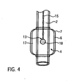
- Fig. 4 shows an illustration of the enlarged view of the cuff 4 of Fig. 2 rotated by 90°.
- the temperature sensor 13 is arranged between the inner balloon 6 and the outer balloon 7 of the cuff 4 and the connecting wires 15 extend between the inner balloon 6 and the outer balloon 7 to the breathing tube 2 and further within the breathing tube 2 up to above of the border G for the part of the breathing tube 2 insertable into the trachea.
- the protective foil 18 covering the measuring head 14 and the connection of the connecting wires 15 to the measuring head can clearly be seen.
- the pressure chamber 17 between the inner balloon 6 of the cuff 4 and the breathing tube 2 is filled by a gas via the connecting piece 11 and the ventilation cannula, and it is loaded by an inflation pressure, wherein the inflation pressure of the trachea sealing cuff 4 is to be limited to a possibly low value for the just sufficient sealing to minimize the traumatic stress caused by the contact pressure of the cuff against the walls of the trachea.
- the inner balloon 6 expands and rests with its outer side on the inner side of the outer balloon 7.
- the outer balloon 7 as in conventional high-volume low-pressure cuffs has a diameter adapted to the size of the trachea 3, the outer side evenly and smoothly rests at the mucosa of the trachea also at low inflation pressure. Since the inner balloon 6 is also composed of a flexible material, the outer wall of the inner balloon evenly rests at the inner wall of the outer balloon 7. Thereby a favorable contact of the temperature sensor 13 covered by the protective foil 18 arranged on the outer wall of the inner balloon 6 is achieved.
- the flexibility of the inner balloon 6 in connection with the low inflation pressure in the pressure chamber 17 effects that the bulges caused by the measuring head 14 and the connecting wires 15 form substantially in the direction of the pressure chamber 17.
- a substantially unhindered envelope sealing surface 5 is produced, i.e. the outer side of the outer balloon 7, so that caused by the arrangement of the temperature sensor 13 on the cuff 4 an additional traumatic stress of the trachea is not produced.
- the arrangement of the temperature sensor 13 between the inner balloon 6 and the outer balloon 7 of the cuff 4 first of all enables a safe build-up of the inflation pressure in the unobstructed pressure space 17 between the inner balloon 6 and the breathing tube 2 and a comfortable rest of the measuring head 14 or the overlying protective foil 18 on the inner wall of the outer balloon 7. Since the outer balloon 7 of the cuff 4 caused by the inflation pressure in the pressure chamber 17 rests tightly on the wall of the trachea 3, a tight contact of the measuring head 14 to the wall of the trachea 3 is obtained.
- the resistance to be bridged for temperature measurement is only limited to the small wall thickness of the outer balloon 7.
- a thermally conductive protective foil 18, e.g. a self-adhesive aluminum foil above the measuring head 14 further improves the measurement of the body core temperature, since possible unevenness caused by the shape of the measuring head, the attachment on the inner balloon 6 and the connection of the connecting wires 15 on the measuring head 14 are compensated or bypassed.
- a larger surface area of the trachea can be utilized for determining the body temperature.
- respiratory gas or breathing air flows during inspiration from a pressure or volume controlled respirator via the breathing tube 2 into the lungs of the patient, according to the arrows shown in Fig. 1 .
- the entire breathing air generated by the breathing apparatus flows into the patient's lungs.
- the pressure and the volume of the breathing air first of all reduces so that caused by the missing pressure or volume of the breathing apparatus the breathing air flows back from the lungs of the patient through the breathing tube 2.
Landscapes
- Health & Medical Sciences (AREA)
- Pulmonology (AREA)
- Emergency Medicine (AREA)
- Engineering & Computer Science (AREA)
- Anesthesiology (AREA)
- Biomedical Technology (AREA)
- Heart & Thoracic Surgery (AREA)
- Hematology (AREA)
- Life Sciences & Earth Sciences (AREA)
- Animal Behavior & Ethology (AREA)
- General Health & Medical Sciences (AREA)
- Public Health (AREA)
- Veterinary Medicine (AREA)
- Media Introduction/Drainage Providing Device (AREA)
Description
- The present invention refers to a tracheal tube for respiration of patients by using a breathing tube, which is at least partially insertable into the trachea, comprising a cuff arranged at the part insertable into the trachea around the breathing tube, and comprising a temperature sensor.
- Tracheal tubes for respiration of patients suffering from insufficient or irregular respiration are known in the art in various forms and embodiments and serve for introducing respiratory gas into the lungs of a patient. For this purpose, the shaft of a tube is endotracheally or tracheostomatically inserted into the trachea of the patient. A cuff is provided at the distal end of the part of the breathing tube inserted into the trachea, said cuff ensuring the sealing between the breathing tube and the trachea. For this purpose the trachea sealing cuff is first of all filled by a gas as soon as the breathing tube is located at its destined position in the trachea. Usually, the cuff is filled with gas independent of the respiratory air, wherein the pressure when inflating the cuff is set to the lowest possible value in order to avoid traumata. The inflated cuff effects that the respiratory gas reaches the lower parts of the respiratory system to thereby ensure sufficient oxygen supply of the patient.
- Patients, who are ventilated by means of a tracheal tube, must frequently also be monitored as to their general clinical state with respect to body temperature. The precise measurement of the body core temperature is an important aspect of clinical monitoring in the context of general anesthesia and other critical states. When administering blood transfusions and intravenous liquids an excessive temperature can lead to a significant rise of the body core temperature of the patient and it can increase the oxygen consumption of the body, which can cause hypoxia of the brain and other organs. Administering too cold intravenous solutions can, on the other hand, lead to hypothermia, which can cause a decrease of the oxygen content in the body. To monitor the body core temperature separate temperature probes are usually placed in various orifices of the body. Besides oral and anal temperature measurement, special temperature probes exist for the tympanic membrane, the nasopharynx, the esophagus, the lungs and the rectum.
- The position for these temperature probes must be localized carefully and the probe itself must safely be fixed.
- Caused by the frequent connection of monitoring the body core temperature of endotracheally or tracheostomatically ventilated patients, the combination of temperature sensors with tracheal tubes for the respiration of patients has long been known in the prior art.
-
DE 19543072 A1 describes for instance a tracheal tube comprising a temperature sensor for measuring the body core temperature. The temperature sensor is arranged at the distal end of the breathing tube below the cuff. Although this arrangement of the sensor neither affects the sealing nor the trachea itself, however, the temperature sensor is arranged at a significant distance to the trachea. Additionally, the proximity of the sensor to the outlet orifice for the respiratory gas influences the accuracy of temperature measurement. -
US 4,046,139 on the other hand shows a temperature sensor, which substantially abuts a wall of the trachea. The sensor is either attached at the tip of the breathing tube or on the inner side of the trachea sealing cuff. In these embodiments in impreciseness of temperature measurement has also proven as having an adverse effect. -
WO 2006/002364 discloses an endotracheal tube comprising an outer and an inner cuff and a temperature sensor which lies in the inner cuff. Thus, the present invention is based on the object of avoiding or improving the disadvantages of the embodiments of tracheal tubes with temperature sensors known from the prior art. - This object is solved by the generic tracheal tube with temperature sensor according to the invention in that the cuff has an outer balloon and an inner balloon and the temperature sensor is arranged between the outer balloon and the inner balloon and is attached on the outer side of the inner balloon.
- Such a tracheal tube with temperature sensor according to the invention enables by the arrangement of the sensor between the outer balloon and the inner balloon of the trachea sealing cuff a favorable and uniform contact pressure of the temperature sensor with respect to the trachea and thereby also a favorable rest of the sensor on the trachea which is required for temperature measurement and that is only separated by the low wall thickness of the outer balloon. The temperature sensor is on the one hand protected by the outer balloon against corrosive or aggressive influences from the trachea, on the other hand the outer balloon reduces the risk of possible traumatic damage on the trachea caused by the temperature sensor. The integration of the temperature sensor between the outer balloon and the inner balloon of the cuff therefore enables a safe and precise measurement of the body core temperature. Compared to the tracheal tubes known in the prior art having dual or double cuffs, which are either arranged offset with respect to each other or stacked on one another on the breathing tube, the outer balloon and the inner balloon of the one cuff of the tracheal tube according to the invention only have a low distance to each other, which substantially serves for receiving the measuring head and the connection wires of the temperature sensor.
- A purposeful embodiment provides that the temperature sensor is attached on the outer side of the inner balloon by means of an adhesive. Such an arrangement of the temperature sensor enables besides the simple attachment also a free and specific positioning of the temperature sensor in the cuff and thus also with respect to the trachea. Besides the attachment of the temperature sensor on the outer side of the inner balloon, an attachment on the inner side of the outer balloon is also possible. Furthermore, the temperature sensor can be embedded on the outer side of the inner balloon, whereby the temperature sensor projects less with respect to the outer side of the inner balloon and therefore also exerts a lower selective pressure via the outer balloon to the trachea.
- A preferred modification allows that a protective layer is provided, and the protective layer covers the temperature sensor towards the outer balloon. The protective layer further reduces the selective pressure of the temperature sensor onto the trachea and thereby reduces the risk of traumatic damage in the trachea. The protective layer can be positioned independent of the attachment of the temperature sensor between the temperature sensor and the outer balloon. Particularly when the temperature sensor is attached on or in the inner balloon, the protective layer can also easily be attached on the outer side of the inner balloon above the temperature sensor. Furthermore, the protective layer or a further protective layer can cover the temperature sensor with respect to the inner balloon to avoid a perforation of the inner balloon by the measuring head of the temperature sensor or its terminals. It is also advantageous if the protective layer is a metal foil, preferably an aluminum foil. The design of the protective layer of a metal foil or aluminum foil improves the head conductance of the trachea and increases the surface of the trachea considered for the temperature measurement. The use of a protective metal layer increases the accuracy of the measurement of the body core temperature and reduces the risk of systematic measuring errors caused by positioning problems. It is advantageous for the manufacture of the tracheal tube according to the invention that the metal foil or aluminum foil is a self-adhesive foil.
- The outer balloon and the inner balloon of the cuff of a tracheal tube according to the invention can usually be made of the same material. The use of the same materials reduces particularly in connection with the same configuration the expenditure in manufacturing. Conventional high-volume/low-pressure trachea sealing cuffs for a uniform and gentle contact of the envelope sealing face on the trachea are made of a flexible material. The diameter of the balloon is dimensioned so large that it already contacts the trachea at a very low inflation pressure of e.g. 15 millibar without revealing a significant flexible deformation. The entire wall thickness of a cuff composed of an outer balloon and an inner balloon is compared to conventional cuffs composed of one membrane only with a wall thickness of up to approx. 0.2 mm somewhat larger, however, it remains below the double value. The wall thicknesses of the outer balloon and of the inner balloon amount to approx. 0.1. to 0.15 mm, wherein the wall thickness of the inner balloon can be significantly lower caused by the additional protection of the outer balloon than the wall thickness of the outer balloon.
- A further embodiment of the tracheal tube according to the invention provides that the inner balloon of the cuff is made of a more flexible material than the outer balloon. Caused by the use of differently flexible materials for the inner balloon and the outer balloon an improved contact pressure behavior of the temperature sensor to the outer balloon of the cuff and thus to the trachea of the patient can be reached. Furthermore, a bulge caused by the arrangement of the temperature sensor between the inner balloon and the outer balloon extends substantially towards the inside so that the trachea is substantially not stressed.
- A favorable embodiment provides that the temperature sensor is a NTC sensor. An NTC resistance sensor or hot-carrier thermal resistor is well adapted for use in measuring the body core temperature. An NTC sensor conducts current better at high temperatures than at low temperatures so that a negative temperature coefficient (NTC) is produced. Caused by the limited application area the electrical resistance changes more upon changing temperatures than with other sensors, so that besides a sensitive and fast reaction of the NTC sensor a high precision is also possible. For the use in the tracheal tube according to the invention the measuring head of the NTC resistance sensor is preferably formed spherically or knob-shaped. With a measuring head diameter of approx. 1.5 mm, the risk of injury for the mucosa of the trachea but also the risk of a perforation of the outer balloon or the inner balloon of the cuff can be reduced. A suitable temperature sensor is for instance provided by the company Betatherm Sensors under the designation Betacurve, which is particularly adapted for use in medical application.
- The connection wires of the temperature sensor can purposefully extend in the cuff up to the breathing tube between the inner balloon and the outer balloon. Such a positioning of the connection wires of the temperature sensor leading to the measuring head prevents by a passage of the connection wires through the inner balloon into the interior of the cuff and thus it also prevents the risk of possible defects and holes in the inner balloon. Defects and holes in the inner balloon lead to a deterioration of the contact pressure of the sensor or of the measuring head on the trachea, since part of the pressure exerted in the trachea sealing cuff is not output via the inner balloon but directly onto the outer balloon. By placing the connection wires between the inner balloon and the outer balloon of the cuff the corrosion protection reached by the respective positioning of the temperature sensor is further improved with respect to corrosive influences from the trachea and with respect to the medium used for pressure build-up in the cuff.
- To reduce the load and traumatic damage, the connection wires of the temperature sensor at least in the part insertable into the trachea can be arranged within and/or integrated in the breathing tube. The part of the tube insertable into the trachea is the part of the breathing tube, which is inserted into the body or the trachea of the patient when using the tracheal tube for ventilating patients, usually 50 to 80 % of the length of the breathing tube. Occasionally, the part of the tube that is not inserted into the trachea is shortened in clinical use and the connection piece for connection with the respirator is inserted onto the shortened tube again so that the part of the breathing tube actually inserted into the trachea can also be significantly larger. In the part of the breathing tube insertable into the trachea the connection wires of the temperature sensor and ventilation cannulas for supplying the cuff are arranged integrated in and/or parallel to the breathing tube. Such a positioning of the connection wires and of the ventilating cannulas avoids the presence of mutually interfering lines and reduces the number of the lines to be inserted into the trachea so that both intubation itself as well as the presence of the tracheal tube in the trachea is less stressful for the patient and interfering influences are avoided.
- The structure and the mode of operation of an embodiment of the present invention will now be explained in detail by means of the enclosed drawing.
-
Fig. 1 shows a tracheal tube according to the invention comprising a cuff arranged in the trachea, -
Fig. 2 shows an enlarged view of the cuff ofFig. 1 , -
Fig. 3 shows the temperature sensor ofFig. 2 , and -
Fig. 4 shows an enlarged view of the cuff ofFig. 2 in a view rotated about 90°. -
Fig. 1 shows a tracheal tube according to the invention for the endotracheal use in a side view. The tracheal tube 1 comprises aflexible breathing tube 2, which in a known manner is inserted into the trachea 3, and which is connected on its upper end with a pressure controlled respirator (now shown), which serves for the periodical inspiration of respiratory gas into a patient's lungs. Thebreathing tube 2 is provided on its lung-sided end inserted into the trachea 3 with atrachea sealing cuff 4. The barrel-shapedcuff 4 is made of a thin flexible material and rests with its outerenvelope sealing surface 5 on the wall of the trachea 3 to ensure sealing between thebreathing tube 2 and the trachea 3. Besides the barrel-shapedcuff 4 shown, a cylindrical or spherical design of thecuff 4 is also possible for the tracheal tube 1 according to the invention. Thetrachea sealing cuff 4 is composed of aninner balloon 6 and anouter balloon 7, wherein theouter balloon 7 completely encompasses theinner balloon 6. Theinner balloon 6 and theouter balloon 7 are both connected on their front end sides with thebreathing tube 2 in an air-tight manner. Theouter balloon 7 is preferably made of a non-transparent material, whereas theinner balloon 6 is made of a material that is flexible compared to the material of theouter balloon 7, which contrary to theouter balloon 7 can also be transparent. - The
cuff 4 is filled by means of aventilation cannula 8 with a pressurized gas. Theventilation cannula 8 extends in the part of thebreathing tube 2 insertable into the trachea 3, i.e. between the border G of the part of thebreathing tube 2 insertable into the trachea and thecuff 4, within the wall or in the interior of thebreathing tube 2 and opens with itsopening 9 into theinner balloon 6 of the cuff. On thedistal end 10 facing away from thecuff 4 theventilation cannula 8 opens into a separate connectingpiece 11, which serves for filling thetrachea sealing cuff 4 and at the same time as a return valve for maintaining the inflation pressure in thecuff 4. Thebreathing tube 2 opens at the end not insertable into the trachea 3, i.e. the end facing away from thecuff 4, into a connectingpiece 12, which is used for ventilating the patient by a usually pressure-controlled respirator. - A
temperature sensor 13 is embedded between theinner balloon 6 and theouter balloon 7 of thecuff 4 in the area of theenvelope seal surface 5 resting on the trachea 3. The measuringhead 14 of thetemperature sensor 13 is fixed in position via theinner balloon 6 or theouter balloon 7. The connectingwires 15 of thetemperature sensor 13 connected with the measuringhead 14 extend between theinner balloon 6 and theouter balloon 7 along the envelope sealing surface and the front end side of the cuff facing away from the lungs to thebreathing tube 2 and in the area of the connection of theinner balloon 6 and the outer balloon with thebreathing tube 2 through thebreathing tube 2 into the interior of thebreathing tube 2. In the interior of thebreathing tube 2 the connectingwires 15 extend without or with an additional protection by a suitable sleeve or embedding into the wall of thebreathing tube 2 up to an area of thebreathing tube 2 above the border G of the part of thebreathing tube 2 insertable into the trachea 3. Above the border G the connectingwires 15 are passed through thebreathing tube 2 towards the outside and end in aplug 16, which can be connected to a respective device for monitoring the body core temperature. - Besides the embodiment of the tracheal tube 1 for endotracheal application shown in
Fig. 1 , a tracheal tube 1 according to the invention can be formed in the same way for a tracheostomatomatic application. The structure and the mode of operation is adapted according to thecuff 4 arranged at the lung-sided end of thebreathing tube 2 withtemperature sensors 13 according to the tracheal tube 1 for endotracheal applications shown inFig. 1 . -
Fig. 2 shows thetrachea sealing cuff 4 arranged at the lung-sided end of thebreathing tube 2 in an enlarged view. Besides the barrel-shaped design of thecuff 4, theinner balloon 6 and theouter balloon 7 can also clearly be recognized in this view. Theopening 9 of theventilation cannula 8 opens through the wall of thebreathing tube 2 into theannular pressure chamber 17 formed between theinner balloon 6 and thebreathing tube 2. Thetemperature sensor 13 is arranged between theinner balloon 6 and theouter balloon 7 on the side of thecuff 4 facing away from theopening 9 of theventilation cannula 8. - As can more clearly be seen in the enlarged view of the detail III of
Fig. 2 inFig. 3 , the spherical or knob-shaped measuringhead 14 of thetemperature sensor 13 is attached on the outer side of theinner balloon 6, e.g. by means of an adhesive and/or a form-fit connection. The connectingwires 15 extend from the measuringhead 14 between theinner balloon 6 and theouter balloon 7 up to the connection of thecuff 4 at thebreathing tube 2. The measuringhead 14 and the surrounding area are covered by aprotective foil 18 made of aluminum. The measuring head is not only additionally or alternatively fixed on the outer side of the inner balloon, but the end of the connectingwires 15 as well as their connection of the measuringhead 14 is also protected. The measuringhead 14 of thetemperature sensor 13 is embedded between theinner balloon 6 and theprotective foil 18. - The
outer balloon 7 is arranged on the outer side of theinner balloon 6 or above theprotective foil 18 facing away from thepressure chamber 17, wherein the inner side of theouter balloon 7 substantially contacts the outer side of theinner balloon 6 and the outer side of theprotective foil 18. -
Fig. 4 shows an illustration of the enlarged view of thecuff 4 ofFig. 2 rotated by 90°. Again, thetemperature sensor 13 is arranged between theinner balloon 6 and theouter balloon 7 of thecuff 4 and the connectingwires 15 extend between theinner balloon 6 and theouter balloon 7 to thebreathing tube 2 and further within thebreathing tube 2 up to above of the border G for the part of thebreathing tube 2 insertable into the trachea. In this illustration theprotective foil 18 covering the measuringhead 14 and the connection of the connectingwires 15 to the measuring head can clearly be seen. - The mode of operation of the tracheal tube 1 with
temperature sensor 13 will now be explained in detail. - After inserting the tracheal tube 1 into the trachea 3 of a patient, the
pressure chamber 17 between theinner balloon 6 of thecuff 4 and thebreathing tube 2 is filled by a gas via the connectingpiece 11 and the ventilation cannula, and it is loaded by an inflation pressure, wherein the inflation pressure of thetrachea sealing cuff 4 is to be limited to a possibly low value for the just sufficient sealing to minimize the traumatic stress caused by the contact pressure of the cuff against the walls of the trachea. When filling thepressure chamber 17 theinner balloon 6 expands and rests with its outer side on the inner side of theouter balloon 7. Since theouter balloon 7, as in conventional high-volume low-pressure cuffs has a diameter adapted to the size of the trachea 3, the outer side evenly and smoothly rests at the mucosa of the trachea also at low inflation pressure. Since theinner balloon 6 is also composed of a flexible material, the outer wall of the inner balloon evenly rests at the inner wall of theouter balloon 7. Thereby a favorable contact of thetemperature sensor 13 covered by theprotective foil 18 arranged on the outer wall of theinner balloon 6 is achieved. Irrespective of whether theinner balloon 6 is made of a more flexible or more elastic material than theouter balloon 7, the flexibility of theinner balloon 6 in connection with the low inflation pressure in thepressure chamber 17 effects that the bulges caused by the measuringhead 14 and the connectingwires 15 form substantially in the direction of thepressure chamber 17. For the contact to the wall of the trachea 3 a substantially unhinderedenvelope sealing surface 5 is produced, i.e. the outer side of theouter balloon 7, so that caused by the arrangement of thetemperature sensor 13 on thecuff 4 an additional traumatic stress of the trachea is not produced. - The arrangement of the
temperature sensor 13 between theinner balloon 6 and theouter balloon 7 of thecuff 4 first of all enables a safe build-up of the inflation pressure in theunobstructed pressure space 17 between theinner balloon 6 and thebreathing tube 2 and a comfortable rest of the measuringhead 14 or the overlyingprotective foil 18 on the inner wall of theouter balloon 7. Since theouter balloon 7 of thecuff 4 caused by the inflation pressure in thepressure chamber 17 rests tightly on the wall of the trachea 3, a tight contact of the measuringhead 14 to the wall of the trachea 3 is obtained. The resistance to be bridged for temperature measurement is only limited to the small wall thickness of theouter balloon 7. Additional negative parameters and disturbances resulting from particularly inaccurate distances of the measuringhead 14 to the wall of the trachea 3, can thereby be eliminated. The arrangement of a thermally conductiveprotective foil 18, e.g. a self-adhesive aluminum foil above the measuringhead 14 further improves the measurement of the body core temperature, since possible unevenness caused by the shape of the measuring head, the attachment on theinner balloon 6 and the connection of the connectingwires 15 on the measuringhead 14 are compensated or bypassed. Through the head conductance of the protective foil, a larger surface area of the trachea can be utilized for determining the body temperature. - After positioning the tracheal tube 1 in the trachea 3 of the patient and after sealing the
breathing tube 2 against the trachea 3 by means of thetrachea sealing cuff 4, respiratory gas or breathing air flows during inspiration from a pressure or volume controlled respirator via thebreathing tube 2 into the lungs of the patient, according to the arrows shown inFig. 1 . Usually, the entire breathing air generated by the breathing apparatus flows into the patient's lungs. During expiration, the pressure and the volume of the breathing air first of all reduces so that caused by the missing pressure or volume of the breathing apparatus the breathing air flows back from the lungs of the patient through thebreathing tube 2. Since thecuff 4 independent of the inspiration or expiration by the breathing apparatus permanently contacts the trachea 3 via theenvelope sealing surface 5, since the gas volume in thepressure chamber 17 is permanently pressurized and is held by the return function of the connectingpiece 12, a safe measurement of the body core temperature is possible independent of the respiration cycle.
Claims (11)
- Tracheal tube (1) for ventilating patients by using a breathing tube (2), which is at least partially insertable into the trachea (3), comprising a cuff (4) arranged at the part insertable into the trachea (3) around the breathing tube (2), and comprising a temperature sensor (13),
characterized in that the cuff (4) comprises an outer balloon (7) and an inner balloon (6) and the temperature sensor (13) is attached on the outer side of the inner balloon (6). - Tracheal tube (1) as claimed in claim 1,
characterized in that the temperature sensor (13) is attached on the outer side of the inner balloon (6) by means of an adhesive. - Tracheal tube (1) as claimed in claim 1,
characterized in that the temperature sensor (13) is embedded into the outer side of the inner balloon (6). - Tracheal tube (1) as claimed in one of claims 1 to 3,
characterized in that a protective layer (18) is provided and the protective layer (18) covers the temperature sensor (13) with respect to the outer balloon (7). - Tracheal tube (1) as claimed in one of claims 1 to 4,
characterized in that a protective layer (18) is provided and the protective layer (18) covers the temperature sensor (13) with respect to the inner balloon (6). - Tracheal tube (1) as claimed in claim 4 or 5,
characterized in that the protective layer (18) is a metal foil, preferably an aluminum foil. - Tracheal tube (1) as claimed in one of claims 1 to 6,
characterized in that the outer balloon (7) and the inner balloon (6) of the cuff (4) are made of the same material. - Tracheal tube (1) as claimed in one of claims 1 to 6,
characterized in that the inner balloon (6) is made of a more flexible material than the outer balloon (7). - Tracheal tube (1) as claimed in one of claims 1 to 8,
characterized in that the temperature sensor (13) is a NTC sensor. - Tracheal tube (1) as claimed in one of claims 1 to 9,
characterized in that the connecting wires (15) of the temperature sensor (13) extend up to the breathing tube (2) between the inner balloon (6) and the outer balloon (7). - Tracheal tube (1) as claimed in one of claims 1 to 10,
characterized in that the connecting wires (15) of the temperature sensor (13) are arranged at least in the part insertable into the trachea (3) within and/or integrated in the breathing tube (2).
Applications Claiming Priority (2)
| Application Number | Priority Date | Filing Date | Title |
|---|---|---|---|
| DE102009053067A DE102009053067A1 (en) | 2009-11-13 | 2009-11-13 | Tracheal tube with temperature sensor |
| PCT/EP2010/006940 WO2011057818A1 (en) | 2009-11-13 | 2010-11-15 | Tracheal tube with temperature sensor |
Publications (2)
| Publication Number | Publication Date |
|---|---|
| EP2498850A1 EP2498850A1 (en) | 2012-09-19 |
| EP2498850B1 true EP2498850B1 (en) | 2014-01-08 |
Family
ID=43428639
Family Applications (1)
| Application Number | Title | Priority Date | Filing Date |
|---|---|---|---|
| EP10778883.8A Not-in-force EP2498850B1 (en) | 2009-11-13 | 2010-11-15 | Tracheal tube with temperature sensor |
Country Status (6)
| Country | Link |
|---|---|
| US (1) | US20120279500A1 (en) |
| EP (1) | EP2498850B1 (en) |
| DE (1) | DE102009053067A1 (en) |
| ES (1) | ES2453368T3 (en) |
| PT (1) | PT2498850E (en) |
| WO (1) | WO2011057818A1 (en) |
Families Citing this family (27)
| Publication number | Priority date | Publication date | Assignee | Title |
|---|---|---|---|---|
| US20120172749A1 (en) * | 2009-12-10 | 2012-07-05 | He Kongyuan | Laryngeal Mask Airway (LMA) with Integrated Core Temperature Monitor and Display |
| US20120172748A1 (en) * | 2010-12-29 | 2012-07-05 | Dunn Lisa A | Temperature measuring device |
| GB2495771B (en) * | 2011-10-21 | 2018-07-04 | Intersurgical Ag | System for controlling delivery of respiratory gas |
| US20130255677A1 (en) * | 2012-03-30 | 2013-10-03 | Christopher M. Varga | Disposable respiratory circuit coupled with a disposable temperature sensor |
| AU2014228152B2 (en) | 2013-03-15 | 2018-07-05 | The General Hospital Corporation | Synthesis of nitric oxide gas for inhalation |
| BR112015022466B1 (en) * | 2013-03-15 | 2022-11-08 | The General Hospital Corporation | METHOD AND APPARATUS FOR INSPIRATORY SYNTHESIS OF NITRIC OXIDE |
| EP3209359B1 (en) | 2014-10-20 | 2020-07-01 | The General Hospital Corporation | Systems and methods for the synthesis of nitric oxide |
| JP6480598B2 (en) | 2015-04-02 | 2019-03-13 | ヒル−ロム サービシーズ プライヴェート リミテッド | Respirator manifold |
| BR112018069582A2 (en) | 2016-03-25 | 2019-01-22 | Massachusetts Gen Hospital | delivery systems and methods for electrical synthesis of nitric oxide plasma |
| CN110770163B (en) | 2017-02-27 | 2021-08-31 | 第三极股份有限公司 | System and method for mobile generation of nitric oxide |
| CA3054656A1 (en) | 2017-02-27 | 2018-08-30 | Third Pole, Inc. | Systems and methods for generating nitric oxide |
| MX2020010523A (en) | 2017-02-27 | 2021-02-09 | Third Pole Inc | Systems and methods for generating nitric oxide. |
| WO2018183811A1 (en) | 2017-03-31 | 2018-10-04 | The General Hospital Corporation | Systems and methods for a cooled nitric oxide generator |
| JP2022533628A (en) | 2019-05-15 | 2022-07-25 | サード ポール,インコーポレイテッド | Electrodes for nitric oxide generation |
| JP2022532654A (en) | 2019-05-15 | 2022-07-15 | サード ポール,インコーポレイテッド | Systems and methods for producing nitric oxide |
| EP3969016A4 (en) | 2019-05-15 | 2023-08-16 | Third Pole, Inc. | NITROGEN MONOXIDE GENERATION ARCHITECTURES |
| EP4069069A4 (en) | 2020-01-11 | 2024-07-03 | Third Pole, Inc. | SYSTEMS AND METHODS FOR GENERATING NITRIC OXIDE WITH HUMIDITY CONTROL |
| US20210395905A1 (en) | 2020-06-18 | 2021-12-23 | Third Pole, Inc. | Systems and methods for preventing and treating infections with nitric oxide |
| CN111714744A (en) * | 2020-07-13 | 2020-09-29 | 无锡康莱医疗科技有限公司 | Non-inflatable cuff and endotracheal intubation |
| US12509349B2 (en) | 2020-10-16 | 2025-12-30 | Third Pole, Inc. | Nitric oxide generation process controls |
| US20250135137A1 (en) * | 2021-08-20 | 2025-05-01 | Hackensack Meridian Health, Inc. | Endotracheal tube and methods of use |
| GB2611046B (en) * | 2021-09-23 | 2023-10-25 | Willmott Orthopaedics Ltd | Laryngeal mask airway |
| EP4405019A4 (en) | 2021-09-23 | 2025-07-16 | Third Pole Inc | SYSTEMS AND METHODS FOR DELIVERING NITRIC OXIDE |
| WO2023201363A2 (en) | 2022-04-14 | 2023-10-19 | Third Pole, Inc. | Delivery of medicinal gas in a liquid medium |
| US11744972B1 (en) | 2022-06-23 | 2023-09-05 | Kevin Chong Kim | System and method for a tracheostomy tube with a secondary airflow opening and a dual cuff assembly |
| US11602605B1 (en) * | 2022-06-23 | 2023-03-14 | Kevin Chong Kim | System and method for an endotracheal tube cuff assembly |
| US11819611B1 (en) | 2022-06-23 | 2023-11-21 | Kevin Chong Kim | System and method for pressure management and air leak detection of an inflatable cuff in a medical device |
Family Cites Families (20)
| Publication number | Priority date | Publication date | Assignee | Title |
|---|---|---|---|---|
| US4046139A (en) | 1976-08-23 | 1977-09-06 | Bernard Horn | Medical temperature measuring device |
| US4134407A (en) * | 1977-03-25 | 1979-01-16 | Elam James O | External pressure-volume monitor for endotracheal cuff |
| US4328056A (en) * | 1980-07-09 | 1982-05-04 | Sherwood Medical Industries Inc. | Method of making a cuffed tube |
| US4791923A (en) * | 1984-02-21 | 1988-12-20 | Bivona Surgical Instruments, Inc. | Tracheal tubes |
| US4967759A (en) * | 1988-06-29 | 1990-11-06 | Teves Leonides Y | Cardiac monitor with endotracheal sensor |
| US5038777A (en) * | 1991-03-14 | 1991-08-13 | Dunn Margarette T | Endotracheal device |
| US5295489A (en) * | 1991-12-20 | 1994-03-22 | Medi-Tube Corporation | Endotracheal tube/stethoscope/thermistor combination |
| US5342305A (en) * | 1992-08-13 | 1994-08-30 | Cordis Corporation | Variable distention angioplasty balloon assembly |
| US5358487A (en) * | 1993-10-15 | 1994-10-25 | Cordis Corporation | Frangible balloon catheter |
| DE9416465U1 (en) * | 1994-10-13 | 1996-02-08 | Schreiber, Hans, Dr. Dr., 69469 Weinheim | Endotracheal tube |
| DE19543072A1 (en) | 1995-11-11 | 1997-05-15 | Wins Peter Richard | Trachea tube with integral temperature probe |
| US5797948A (en) * | 1996-10-03 | 1998-08-25 | Cordis Corporation | Centering balloon catheter |
| DE19808590C2 (en) * | 1998-02-28 | 2003-03-20 | Draeger Medical Ag | respiratory humidifier |
| AU748342B2 (en) * | 1998-03-09 | 2002-06-06 | Avent, Inc. | Tracheal breathing apparatus |
| US20020065542A1 (en) * | 1998-04-22 | 2002-05-30 | Ronald G. Lax | Method and apparatus for treating an aneurysm |
| IL139721A0 (en) * | 2000-11-16 | 2002-02-10 | Alcor Medical Instr Ltd | Appliance for the body core temperature monitoring and a method therefor |
| US20030041863A1 (en) * | 2001-08-28 | 2003-03-06 | Jackie Hargis | Dual balloon endotracheal tube assembly |
| US20050284482A1 (en) * | 2004-06-24 | 2005-12-29 | Vinu Patel | Endotracheal tube with integral heart, lung, and temperature monitor |
| US8075540B2 (en) * | 2004-11-09 | 2011-12-13 | Hollister Incorporated | Bowel management system with physiologic sensors |
| US8672919B2 (en) * | 2008-09-18 | 2014-03-18 | Cook Medical Technologies Llc | Dual balloon catheter assembly |
-
2009
- 2009-11-13 DE DE102009053067A patent/DE102009053067A1/en not_active Withdrawn
-
2010
- 2010-11-15 US US13/509,098 patent/US20120279500A1/en not_active Abandoned
- 2010-11-15 ES ES10778883.8T patent/ES2453368T3/en active Active
- 2010-11-15 EP EP10778883.8A patent/EP2498850B1/en not_active Not-in-force
- 2010-11-15 PT PT107788838T patent/PT2498850E/en unknown
- 2010-11-15 WO PCT/EP2010/006940 patent/WO2011057818A1/en not_active Ceased
Also Published As
| Publication number | Publication date |
|---|---|
| WO2011057818A1 (en) | 2011-05-19 |
| DE102009053067A1 (en) | 2011-05-19 |
| EP2498850A1 (en) | 2012-09-19 |
| PT2498850E (en) | 2014-01-23 |
| ES2453368T3 (en) | 2014-04-07 |
| US20120279500A1 (en) | 2012-11-08 |
Similar Documents
| Publication | Publication Date | Title |
|---|---|---|
| US20120279500A1 (en) | Tracheal Tube with Temperature Sensor | |
| ES2453367T3 (en) | MEK heterocyclic inhibitors | |
| JP7068428B2 (en) | Medical tubes and their manufacturing methods | |
| US4263921A (en) | Temperature sensing method and endotracheal tube appliance | |
| US20120167882A1 (en) | Temperature monitoring and control devices for tracheal tubes | |
| US8568316B2 (en) | Tracheal tube sensor disposed on permeable membrane | |
| CN102281913A (en) | Pressure measuring syringe | |
| WO2010147760A1 (en) | Tracheal tube with lumen for tracheal pressure measurement and technique for using the same | |
| US20160022939A1 (en) | Cuff pressure measurement device for a tracheal tube | |
| US20110213264A1 (en) | Sensor on non-sealing portion of tracheal tube cuff | |
| US20020068877A1 (en) | Device for measuring body cavity temperature | |
| US20120089041A1 (en) | Ultrasound-observable, respiratory gas-warming, parameter-sensing endotracheal tube | |
| WO2018107567A1 (en) | Pressure indicator | |
| US20120089023A1 (en) | Parameter-sensing endotracheal tube | |
| CN209437841U (en) | An oxygen-absorbing oropharyngeal airway for digestive endoscopy | |
| CN216798432U (en) | Self-feedback type body temperature protection closed-loop heating system | |
| CN208989957U (en) | A kind of tracheal catheter for thering is temperature check to pop one's head in | |
| CN111388830A (en) | Breathing machine pipeline with temperature monitoring device | |
| ES3022186T3 (en) | Active humidifier and thermoregulated circuit integrating such active humidifier | |
| JPH04503164A (en) | Improvements regarding catheters | |
| KR20200068923A (en) | Endotracheal temperature probe | |
| CN107929911A (en) | A kind of oxygen suction humidifying bottle and oxygen heating corollary apparatus | |
| US20070107736A1 (en) | System and method for monitoring temperature while delivering anesthesia | |
| CN221673059U (en) | Temperature measurement shutoff bronchus intubate | |
| CN113440708A (en) | Trachea cannula for trachea and bronchus interventional therapy |
Legal Events
| Date | Code | Title | Description |
|---|---|---|---|
| PUAI | Public reference made under article 153(3) epc to a published international application that has entered the european phase |
Free format text: ORIGINAL CODE: 0009012 |
|
| 17P | Request for examination filed |
Effective date: 20120524 |
|
| AK | Designated contracting states |
Kind code of ref document: A1 Designated state(s): AL AT BE BG CH CY CZ DE DK EE ES FI FR GB GR HR HU IE IS IT LI LT LU LV MC MK MT NL NO PL PT RO RS SE SI SK SM TR |
|
| DAX | Request for extension of the european patent (deleted) | ||
| GRAP | Despatch of communication of intention to grant a patent |
Free format text: ORIGINAL CODE: EPIDOSNIGR1 |
|
| GRAJ | Information related to disapproval of communication of intention to grant by the applicant or resumption of examination proceedings by the epo deleted |
Free format text: ORIGINAL CODE: EPIDOSDIGR1 |
|
| GRAP | Despatch of communication of intention to grant a patent |
Free format text: ORIGINAL CODE: EPIDOSNIGR1 |
|
| INTG | Intention to grant announced |
Effective date: 20130710 |
|
| INTG | Intention to grant announced |
Effective date: 20130725 |
|
| GRAS | Grant fee paid |
Free format text: ORIGINAL CODE: EPIDOSNIGR3 |
|
| GRAA | (expected) grant |
Free format text: ORIGINAL CODE: 0009210 |
|
| AK | Designated contracting states |
Kind code of ref document: B1 Designated state(s): AL AT BE BG CH CY CZ DE DK EE ES FI FR GB GR HR HU IE IS IT LI LT LU LV MC MK MT NL NO PL PT RO RS SE SI SK SM TR |
|
| REG | Reference to a national code |
Ref country code: GB Ref legal event code: FG4D |
|
| REG | Reference to a national code |
Ref country code: CH Ref legal event code: EP Ref country code: CH Ref legal event code: NV Representative=s name: PATENTANWALTSBUERO JEAN HUNZIKER AG, CH |
|
| REG | Reference to a national code |
Ref country code: PT Ref legal event code: SC4A Free format text: AVAILABILITY OF NATIONAL TRANSLATION Effective date: 20140116 |
|
| REG | Reference to a national code |
Ref country code: IE Ref legal event code: FG4D |
|
| REG | Reference to a national code |
Ref country code: AT Ref legal event code: REF Ref document number: 648271 Country of ref document: AT Kind code of ref document: T Effective date: 20140215 |
|
| REG | Reference to a national code |
Ref country code: DE Ref legal event code: R096 Ref document number: 602010013039 Country of ref document: DE Effective date: 20140220 |
|
| REG | Reference to a national code |
Ref country code: NL Ref legal event code: T3 |
|
| REG | Reference to a national code |
Ref country code: ES Ref legal event code: FG2A Ref document number: 2453368 Country of ref document: ES Kind code of ref document: T3 Effective date: 20140407 |
|
| REG | Reference to a national code |
Ref country code: LT Ref legal event code: MG4D |
|
| PG25 | Lapsed in a contracting state [announced via postgrant information from national office to epo] |
Ref country code: LT Free format text: LAPSE BECAUSE OF FAILURE TO SUBMIT A TRANSLATION OF THE DESCRIPTION OR TO PAY THE FEE WITHIN THE PRESCRIBED TIME-LIMIT Effective date: 20140108 Ref country code: IS Free format text: LAPSE BECAUSE OF FAILURE TO SUBMIT A TRANSLATION OF THE DESCRIPTION OR TO PAY THE FEE WITHIN THE PRESCRIBED TIME-LIMIT Effective date: 20140508 Ref country code: NO Free format text: LAPSE BECAUSE OF FAILURE TO SUBMIT A TRANSLATION OF THE DESCRIPTION OR TO PAY THE FEE WITHIN THE PRESCRIBED TIME-LIMIT Effective date: 20140408 |
|
| PG25 | Lapsed in a contracting state [announced via postgrant information from national office to epo] |
Ref country code: CY Free format text: LAPSE BECAUSE OF FAILURE TO SUBMIT A TRANSLATION OF THE DESCRIPTION OR TO PAY THE FEE WITHIN THE PRESCRIBED TIME-LIMIT Effective date: 20140108 Ref country code: SE Free format text: LAPSE BECAUSE OF FAILURE TO SUBMIT A TRANSLATION OF THE DESCRIPTION OR TO PAY THE FEE WITHIN THE PRESCRIBED TIME-LIMIT Effective date: 20140108 Ref country code: FI Free format text: LAPSE BECAUSE OF FAILURE TO SUBMIT A TRANSLATION OF THE DESCRIPTION OR TO PAY THE FEE WITHIN THE PRESCRIBED TIME-LIMIT Effective date: 20140108 |
|
| PG25 | Lapsed in a contracting state [announced via postgrant information from national office to epo] |
Ref country code: LV Free format text: LAPSE BECAUSE OF FAILURE TO SUBMIT A TRANSLATION OF THE DESCRIPTION OR TO PAY THE FEE WITHIN THE PRESCRIBED TIME-LIMIT Effective date: 20140108 Ref country code: RS Free format text: LAPSE BECAUSE OF FAILURE TO SUBMIT A TRANSLATION OF THE DESCRIPTION OR TO PAY THE FEE WITHIN THE PRESCRIBED TIME-LIMIT Effective date: 20140108 Ref country code: HR Free format text: LAPSE BECAUSE OF FAILURE TO SUBMIT A TRANSLATION OF THE DESCRIPTION OR TO PAY THE FEE WITHIN THE PRESCRIBED TIME-LIMIT Effective date: 20140108 |
|
| REG | Reference to a national code |
Ref country code: DE Ref legal event code: R097 Ref document number: 602010013039 Country of ref document: DE |
|
| PG25 | Lapsed in a contracting state [announced via postgrant information from national office to epo] |
Ref country code: EE Free format text: LAPSE BECAUSE OF FAILURE TO SUBMIT A TRANSLATION OF THE DESCRIPTION OR TO PAY THE FEE WITHIN THE PRESCRIBED TIME-LIMIT Effective date: 20140108 Ref country code: CZ Free format text: LAPSE BECAUSE OF FAILURE TO SUBMIT A TRANSLATION OF THE DESCRIPTION OR TO PAY THE FEE WITHIN THE PRESCRIBED TIME-LIMIT Effective date: 20140108 Ref country code: DK Free format text: LAPSE BECAUSE OF FAILURE TO SUBMIT A TRANSLATION OF THE DESCRIPTION OR TO PAY THE FEE WITHIN THE PRESCRIBED TIME-LIMIT Effective date: 20140108 Ref country code: RO Free format text: LAPSE BECAUSE OF FAILURE TO SUBMIT A TRANSLATION OF THE DESCRIPTION OR TO PAY THE FEE WITHIN THE PRESCRIBED TIME-LIMIT Effective date: 20140108 |
|
| PLBE | No opposition filed within time limit |
Free format text: ORIGINAL CODE: 0009261 |
|
| STAA | Information on the status of an ep patent application or granted ep patent |
Free format text: STATUS: NO OPPOSITION FILED WITHIN TIME LIMIT |
|
| PG25 | Lapsed in a contracting state [announced via postgrant information from national office to epo] |
Ref country code: SK Free format text: LAPSE BECAUSE OF FAILURE TO SUBMIT A TRANSLATION OF THE DESCRIPTION OR TO PAY THE FEE WITHIN THE PRESCRIBED TIME-LIMIT Effective date: 20140108 Ref country code: PL Free format text: LAPSE BECAUSE OF FAILURE TO SUBMIT A TRANSLATION OF THE DESCRIPTION OR TO PAY THE FEE WITHIN THE PRESCRIBED TIME-LIMIT Effective date: 20140108 |
|
| 26N | No opposition filed |
Effective date: 20141009 |
|
| REG | Reference to a national code |
Ref country code: DE Ref legal event code: R097 Ref document number: 602010013039 Country of ref document: DE Effective date: 20141009 |
|
| PG25 | Lapsed in a contracting state [announced via postgrant information from national office to epo] |
Ref country code: SI Free format text: LAPSE BECAUSE OF FAILURE TO SUBMIT A TRANSLATION OF THE DESCRIPTION OR TO PAY THE FEE WITHIN THE PRESCRIBED TIME-LIMIT Effective date: 20140108 |
|
| REG | Reference to a national code |
Ref country code: DE Ref legal event code: R119 Ref document number: 602010013039 Country of ref document: DE |
|
| REG | Reference to a national code |
Ref country code: NL Ref legal event code: V1 Effective date: 20150601 |
|
| PG25 | Lapsed in a contracting state [announced via postgrant information from national office to epo] |
Ref country code: BE Free format text: LAPSE BECAUSE OF NON-PAYMENT OF DUE FEES Effective date: 20141130 Ref country code: MC Free format text: LAPSE BECAUSE OF FAILURE TO SUBMIT A TRANSLATION OF THE DESCRIPTION OR TO PAY THE FEE WITHIN THE PRESCRIBED TIME-LIMIT Effective date: 20140108 Ref country code: LU Free format text: LAPSE BECAUSE OF FAILURE TO SUBMIT A TRANSLATION OF THE DESCRIPTION OR TO PAY THE FEE WITHIN THE PRESCRIBED TIME-LIMIT Effective date: 20141115 |
|
| REG | Reference to a national code |
Ref country code: CH Ref legal event code: PL |
|
| GBPC | Gb: european patent ceased through non-payment of renewal fee |
Effective date: 20141115 |
|
| PG25 | Lapsed in a contracting state [announced via postgrant information from national office to epo] |
Ref country code: LI Free format text: LAPSE BECAUSE OF NON-PAYMENT OF DUE FEES Effective date: 20141130 Ref country code: CH Free format text: LAPSE BECAUSE OF NON-PAYMENT OF DUE FEES Effective date: 20141130 |
|
| REG | Reference to a national code |
Ref country code: PT Ref legal event code: MM4A Free format text: LAPSE DUE TO NON-PAYMENT OF FEES Effective date: 20150817 |
|
| REG | Reference to a national code |
Ref country code: IE Ref legal event code: MM4A |
|
| REG | Reference to a national code |
Ref country code: FR Ref legal event code: ST Effective date: 20150731 |
|
| PG25 | Lapsed in a contracting state [announced via postgrant information from national office to epo] |
Ref country code: NL Free format text: LAPSE BECAUSE OF NON-PAYMENT OF DUE FEES Effective date: 20150601 |
|
| PG25 | Lapsed in a contracting state [announced via postgrant information from national office to epo] |
Ref country code: DE Free format text: LAPSE BECAUSE OF NON-PAYMENT OF DUE FEES Effective date: 20150602 Ref country code: PT Free format text: LAPSE BECAUSE OF NON-PAYMENT OF DUE FEES Effective date: 20150817 Ref country code: GB Free format text: LAPSE BECAUSE OF NON-PAYMENT OF DUE FEES Effective date: 20141115 Ref country code: IE Free format text: LAPSE BECAUSE OF NON-PAYMENT OF DUE FEES Effective date: 20141115 |
|
| PG25 | Lapsed in a contracting state [announced via postgrant information from national office to epo] |
Ref country code: FR Free format text: LAPSE BECAUSE OF NON-PAYMENT OF DUE FEES Effective date: 20141201 |
|
| REG | Reference to a national code |
Ref country code: ES Ref legal event code: FD2A Effective date: 20151229 |
|
| PG25 | Lapsed in a contracting state [announced via postgrant information from national office to epo] |
Ref country code: IT Free format text: LAPSE BECAUSE OF NON-PAYMENT OF DUE FEES Effective date: 20141115 |
|
| PG25 | Lapsed in a contracting state [announced via postgrant information from national office to epo] |
Ref country code: ES Free format text: LAPSE BECAUSE OF NON-PAYMENT OF DUE FEES Effective date: 20141116 |
|
| PG25 | Lapsed in a contracting state [announced via postgrant information from national office to epo] |
Ref country code: SM Free format text: LAPSE BECAUSE OF FAILURE TO SUBMIT A TRANSLATION OF THE DESCRIPTION OR TO PAY THE FEE WITHIN THE PRESCRIBED TIME-LIMIT Effective date: 20140108 |
|
| PG25 | Lapsed in a contracting state [announced via postgrant information from national office to epo] |
Ref country code: GR Free format text: LAPSE BECAUSE OF FAILURE TO SUBMIT A TRANSLATION OF THE DESCRIPTION OR TO PAY THE FEE WITHIN THE PRESCRIBED TIME-LIMIT Effective date: 20140409 Ref country code: BG Free format text: LAPSE BECAUSE OF FAILURE TO SUBMIT A TRANSLATION OF THE DESCRIPTION OR TO PAY THE FEE WITHIN THE PRESCRIBED TIME-LIMIT Effective date: 20140108 |
|
| PG25 | Lapsed in a contracting state [announced via postgrant information from national office to epo] |
Ref country code: MT Free format text: LAPSE BECAUSE OF FAILURE TO SUBMIT A TRANSLATION OF THE DESCRIPTION OR TO PAY THE FEE WITHIN THE PRESCRIBED TIME-LIMIT Effective date: 20140108 Ref country code: TR Free format text: LAPSE BECAUSE OF FAILURE TO SUBMIT A TRANSLATION OF THE DESCRIPTION OR TO PAY THE FEE WITHIN THE PRESCRIBED TIME-LIMIT Effective date: 20140108 Ref country code: HU Free format text: LAPSE BECAUSE OF FAILURE TO SUBMIT A TRANSLATION OF THE DESCRIPTION OR TO PAY THE FEE WITHIN THE PRESCRIBED TIME-LIMIT; INVALID AB INITIO Effective date: 20101115 |
|
| REG | Reference to a national code |
Ref country code: AT Ref legal event code: PC Ref document number: 648271 Country of ref document: AT Kind code of ref document: T Owner name: MORITZ DR. HAUGK, AT Effective date: 20160809 |
|
| PGFP | Annual fee paid to national office [announced via postgrant information from national office to epo] |
Ref country code: AT Payment date: 20161125 Year of fee payment: 7 |
|
| PG25 | Lapsed in a contracting state [announced via postgrant information from national office to epo] |
Ref country code: MK Free format text: LAPSE BECAUSE OF FAILURE TO SUBMIT A TRANSLATION OF THE DESCRIPTION OR TO PAY THE FEE WITHIN THE PRESCRIBED TIME-LIMIT Effective date: 20140108 |
|
| REG | Reference to a national code |
Ref country code: AT Ref legal event code: MM01 Ref document number: 648271 Country of ref document: AT Kind code of ref document: T Effective date: 20171115 |
|
| PG25 | Lapsed in a contracting state [announced via postgrant information from national office to epo] |
Ref country code: AT Free format text: LAPSE BECAUSE OF NON-PAYMENT OF DUE FEES Effective date: 20171115 |
|
| PG25 | Lapsed in a contracting state [announced via postgrant information from national office to epo] |
Ref country code: AL Free format text: LAPSE BECAUSE OF FAILURE TO SUBMIT A TRANSLATION OF THE DESCRIPTION OR TO PAY THE FEE WITHIN THE PRESCRIBED TIME-LIMIT Effective date: 20140108 |