EP2498409A1 - Method, apparatus and system for downlink pilot transmission - Google Patents
Method, apparatus and system for downlink pilot transmission Download PDFInfo
- Publication number
- EP2498409A1 EP2498409A1 EP10825953A EP10825953A EP2498409A1 EP 2498409 A1 EP2498409 A1 EP 2498409A1 EP 10825953 A EP10825953 A EP 10825953A EP 10825953 A EP10825953 A EP 10825953A EP 2498409 A1 EP2498409 A1 EP 2498409A1
- Authority
- EP
- European Patent Office
- Prior art keywords
- orthogonal sequence
- sub
- dedicated pilots
- frequency
- carriers
- Prior art date
- Legal status (The legal status is an assumption and is not a legal conclusion. Google has not performed a legal analysis and makes no representation as to the accuracy of the status listed.)
- Granted
Links
Images







Classifications
-
- H—ELECTRICITY
- H04—ELECTRIC COMMUNICATION TECHNIQUE
- H04L—TRANSMISSION OF DIGITAL INFORMATION, e.g. TELEGRAPHIC COMMUNICATION
- H04L5/00—Arrangements affording multiple use of the transmission path
- H04L5/003—Arrangements for allocating sub-channels of the transmission path
- H04L5/0048—Allocation of pilot signals, i.e. of signals known to the receiver
- H04L5/0051—Allocation of pilot signals, i.e. of signals known to the receiver of dedicated pilots, i.e. pilots destined for a single user or terminal
-
- H—ELECTRICITY
- H04—ELECTRIC COMMUNICATION TECHNIQUE
- H04L—TRANSMISSION OF DIGITAL INFORMATION, e.g. TELEGRAPHIC COMMUNICATION
- H04L5/00—Arrangements affording multiple use of the transmission path
- H04L5/003—Arrangements for allocating sub-channels of the transmission path
- H04L5/0048—Allocation of pilot signals, i.e. of signals known to the receiver
-
- H—ELECTRICITY
- H04—ELECTRIC COMMUNICATION TECHNIQUE
- H04J—MULTIPLEX COMMUNICATION
- H04J13/00—Code division multiplex systems
- H04J13/0007—Code type
- H04J13/004—Orthogonal
- H04J13/0048—Walsh
-
- H—ELECTRICITY
- H04—ELECTRIC COMMUNICATION TECHNIQUE
- H04L—TRANSMISSION OF DIGITAL INFORMATION, e.g. TELEGRAPHIC COMMUNICATION
- H04L25/00—Baseband systems
- H04L25/02—Details ; arrangements for supplying electrical power along data transmission lines
- H04L25/0202—Channel estimation
- H04L25/0224—Channel estimation using sounding signals
-
- H—ELECTRICITY
- H04—ELECTRIC COMMUNICATION TECHNIQUE
- H04L—TRANSMISSION OF DIGITAL INFORMATION, e.g. TELEGRAPHIC COMMUNICATION
- H04L27/00—Modulated-carrier systems
- H04L27/26—Systems using multi-frequency codes
- H04L27/2601—Multicarrier modulation systems
- H04L27/2602—Signal structure
- H04L27/261—Details of reference signals
- H04L27/2613—Structure of the reference signals
- H04L27/26134—Pilot insertion in the transmitter chain, e.g. pilot overlapping with data, insertion in time or frequency domain
-
- H—ELECTRICITY
- H04—ELECTRIC COMMUNICATION TECHNIQUE
- H04L—TRANSMISSION OF DIGITAL INFORMATION, e.g. TELEGRAPHIC COMMUNICATION
- H04L5/00—Arrangements affording multiple use of the transmission path
- H04L5/0001—Arrangements for dividing the transmission path
- H04L5/0003—Two-dimensional division
- H04L5/0005—Time-frequency
- H04L5/0007—Time-frequency the frequencies being orthogonal, e.g. OFDM(A) or DMT
-
- H—ELECTRICITY
- H04—ELECTRIC COMMUNICATION TECHNIQUE
- H04L—TRANSMISSION OF DIGITAL INFORMATION, e.g. TELEGRAPHIC COMMUNICATION
- H04L5/00—Arrangements affording multiple use of the transmission path
- H04L5/0001—Arrangements for dividing the transmission path
- H04L5/0014—Three-dimensional division
- H04L5/0016—Time-frequency-code
-
- H—ELECTRICITY
- H04—ELECTRIC COMMUNICATION TECHNIQUE
- H04L—TRANSMISSION OF DIGITAL INFORMATION, e.g. TELEGRAPHIC COMMUNICATION
- H04L5/00—Arrangements affording multiple use of the transmission path
- H04L5/0001—Arrangements for dividing the transmission path
- H04L5/0014—Three-dimensional division
- H04L5/0023—Time-frequency-space
-
- H—ELECTRICITY
- H04—ELECTRIC COMMUNICATION TECHNIQUE
- H04L—TRANSMISSION OF DIGITAL INFORMATION, e.g. TELEGRAPHIC COMMUNICATION
- H04L27/00—Modulated-carrier systems
- H04L27/26—Systems using multi-frequency codes
- H04L27/2601—Multicarrier modulation systems
- H04L27/2602—Signal structure
- H04L27/261—Details of reference signals
- H04L27/2613—Structure of the reference signals
Definitions
- the present invention relates to the field of communications and particularly to a method, apparatus and system for transmitting downlink pilots.
- LTE Long Term Evolution
- Dedicated pilots are adopted in the LTE-A system to demodulate data in order to better support the new technologies.
- a dedicated pilot corresponds to a data stream, and pilots keep orthogonal between respective streams.
- CDM Code Division Multiplexing
- FDM Frequency Division Multiplexing
- CDM Code Division Multiplexing
- rank5 rank6, rank7 and rank8
- orthogonality between pilots of the eight streams is ensured in hybrid of FDM and CDM mode.
- the CDM mode is involved for the pilots in all the transmission schemes.
- the power sum of pilots over one Orthogonal Frequency Division Multiplexing (OFDM) symbol may differ from that over another so that the power of one OFDM symbol may differ from that of another.
- OFDM Orthogonal Frequency Division Multiplexing
- the invention provides a method, apparatus and system for transmitting downlink pilots to address the problem in the prior art of different power over different OFDM symbols.
- a frequency-domain granularity is preset, and dedicated pilots are transmitted in the Code Division Multiplexing (CDM) mode or in hybrid of CDM and Frequency Division Multiplexing (FDM) mode, wherein the dedicated pilots are configured with orthogonal sequence sets over resources for transmission of the dedicated pilots according to the preset frequency-domain granularity and rule and the same orthogonal sequence set is adopted for the dedicated pilots in each frequency-domain granularity to thereby address the problem of power differences among OFDM symbols caused by Walsh Codes.
- CDM Code Division Multiplexing
- FDM Frequency Division Multiplexing
- Fig.1 is a schematic flow chart of a transmitting method according to an embodiment of the invention.
- Fig.2 is a schematic flow chart of a receiving method according to an embodiment of the invention.
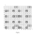
- Fig.3a is a schematic diagram of a rank1-rank2 pilot structure
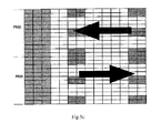
- Fig.3b is a schematic diagram of resource block PRB based inversion with rank2;
- Fig.4a is a schematic diagram of a rank3-rank4 pilot structure and a rank5-rank8 pilot structure
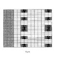
- Fig.4b is a schematic diagram of a sub-carrier based sequence selection scheme with rank3-rank4;
- Fig.4c is a schematic diagram of a sub-carrier group based sequence selection scheme with rank3-rank4;
- Fig.4d is a schematic diagram of a PRB based sequence selection scheme with rank3-rank4;
- Fig.4e is a schematic diagram of rank3-rank4 with a sequence mapping rule at layers 1 and 2 differing from that at layers 3 and 4;
- Fig.5a is a sub-carrier based orthogonal sequence selection scheme with rank5-rank8 at a length of 4;
- Fig.5b is a sub-carrier group based orthogonal sequence selection scheme with PRB rank5-rank8 at a length of 4;
- Fig.5c is a PRB based orthogonal sequence selection scheme with rank5-rank8 at a length of 4;
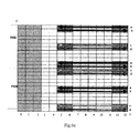
- Fig.6a is a sub-carrier based orthogonal sequence selection scheme with rank5-rank8 at a length of 4;
- Fig.6b is a sub-carrier group based orthogonal sequence selection scheme with rank5-rank8 at a length of 4;
- Fig.6c is a PRB based orthogonal sequence selection scheme with rank5-rank8 at a length of 4;
- Fig.7a is sequence selection (or inversion) only in a PRB
- Fig.7b is sequence selection (or inversion) in a user scheduled resource block
- Fig.7c is sequence selection (or inversion) over a system bandwidth
- Fig.8 is a schematic structural diagram of a transmitting apparatus according to an embodiment of the invention.
- Fig.9 is a schematic structural diagram of a receiving apparatus according to an embodiment of the invention.
- dedicated pilots are transmitted in the Code Division Multiplexing (CDM) mode or in hybrid of CDM and Frequency Division Multiplexing (FDM) mode in the embodiments of the invention, where dedicated pilots are configured with orthogonal sequence sets over resources for transmission of the dedicated pilots according to a preset frequency-domain granularity and rule and the same orthogonal sequence set is adopted for the dedicated pilots in each frequency-domain granularity.
- CDM Code Division Multiplexing
- FDM Frequency Division Multiplexing
- a method for transmitting downlink pilots includes:
- dedicated pilots are mapped in the Code Division Multiplexing (CDM) mode or in hybrid of CDM and Frequency Division Multiplexing (FDM) mode, where the dedicated pilots are configured with orthogonal sequence sets over resources for transmission of the dedicated pilots according to a preset frequency-domain granularity and rule and the same orthogonal sequence set is adopted for the dedicated pilots in each frequency-domain granularity.
- CDM Code Division Multiplexing
- FDM Frequency Division Multiplexing
- the mapped dedicated pilots are transmitted.
- the frequency-domain granularity is a sub-carrier, a group of sub-carriers or a resource block PRB.
- the frequency-domain granularity is a sub-carrier
- one orthogonal sequence set is adopted for each sub-carrier and different orthogonal sequence sets are adopted for adjacent sub-carriers among sub-carriers for transmission of the dedicated pilots in each resource block.
- the frequency-domain granularity is a group of sub-carriers
- the same orthogonal sequence set is adopted in each group of sub-carriers and different orthogonal sequence sets are adopted between adjacent groups of sub-carriers among groups of sub-carriers for transmission of the dedicated pilots in each resource block.
- the frequency-domain granularity is a resource block PRB
- the same orthogonal sequence set is adopted over the resource for transmission of the dedicated pilots in each resource block.
- the dedicated pilots are configured with orthogonal sequence sets according to the preset rule as follows:
- the dedicated pilots are configured with orthogonal sequence sets according to the orthogonal sequence set adopted for the starting PRB of a system bandwidth; or the dedicated pilots are configured with orthogonal sequence sets according to the orthogonal sequence set and the resource block scheduling sequence number, adopted for the starting PRB scheduled by user.
- the dedicated pilots with the configured orthogonal sequence sets are transmitted to a user equipment so as to be provided to the user equipment for channel estimation.
- the dedicated pilots are transmitted over the same sub-carrier in each group of ports in the CDM mode, and a frequency-domain granularity and/or a rule preset for one group of ports may be the same as or different from that for another.
- a frequency-domain granularity and/or a rule preset for one rank-number of system transmission may be the same as or different from that for another.
- different orthogonal sequence sets are adopted for adjacent sub-carriers for transmission of the dedicated pilots in the same group of ports, but different orthogonal sequence sets are adopted for starting sub-carriers of different groups of ports.
- a rank-number of system transmission is 3 or 4
- the same orthogonal sequence is adopted at data layers of transmission 1 and 3, and an orthogonal sequence at layer 4 is opposite to that at layer 2.
- the dedicated pilots with the configured orthogonal sequence sets are transmitted to a user equipment so as to be provided to the user equipment for channel estimation.
- the configured orthogonal sequence sets can be transmitted to the user equipment in a broadcast message or Downlink Control Information (DCI).
- DCI Downlink Control Information
- the orthogonal sequence sets may be not transmitted but, for example, stored in advance at the user equipment.
- a method for receiving downlink pilots includes the following steps:
- the step 201 is to obtain starting PRB orthogonal sequence configuration information, frequency-domain granularity information and rule or configuration information of orthogonal sequence sets.
- the starting PRB resource configuration information, the frequency-domain granularity information and the rule may be configured in advance at the user equipment or updated with configuration information periodically received from the network.
- the orthogonal sequence sets in the dedicated pilots may be obtained by receiving a broadcast message or a DCI message, transmitted from the base station, including orthogonal sequences, or the orthogonal sequence sets in the dedicated pilots may be stored in advance at the user equipment, or the orthogonal sequence sets in the dedicated pilots may be generated by the user equipment according to a rule stored in advance.
- the step 202 is to receive the dedicated pilots according to the obtained starting PRB resource configuration information, frequency-domain granularity information and rule and the obtained orthogonal sequence sets, where the same orthogonal sequence set is adopted for the dedicated pilots in each frequency-domain granularity.
- the frequency-domain granularity as referred here to may also be a sub-carrier, a group of sub-carriers or a resource block PRB.
- a specific granularity in use may be preset by the system or adjusted dependent upon a condition of resources.
- the frequency-domain granularity is a sub-carrier
- one orthogonal sequence set is adopted for each sub-carrier and different orthogonal sequence sets are adopted for adjacent sub-carriers among sub-carriers for transmission of the dedicated pilots in each resource block.
- the frequency-domain granularity is a group of sub-carriers
- the same orthogonal sequence set is adopted in each group of sub-carriers and different orthogonal sequence sets are adopted between adjacent groups of sub-carriers among groups of sub-carriers for transmission of the dedicated pilots in each resource block.
- the frequency-domain granularity is a resource block PRB
- the same orthogonal sequence set is adopted over resources for transmission of the dedicated pilots in each resource block.
- sub-carrier based and sub-carrier group based schemes are identical with rank1-rank2.
- Fig.3a is a schematic diagram of an LTE-A downlink dedicated pilot structure.
- Dedicated pilots are transmitted in the 2 nd , the 7 th and the 12 th sub-carriers in OFDM symbols 5, 6, 12 and 13, where dedicated pilot symbols of dedicated pilot ports 0 and 1 are transmitted over sub-carriers in each OFDM symbol in the CDM mode.
- This embodiment takes what illustrated in Fig.3a as an example, and this illustrated scheme will not be limited to any transmission mode.
- Fig.3b is a schematic diagram of PRB based inversion with rank2.
- the horizontal axis represents time while the vertical axis represents frequency
- the illustrated frame structure includes two PRBs with a shadowed zone representing a zone for transmission of dedicated pilots, and orthogonal sequence inversion (selection) can be performed per PRB, that is, orthogonal sequences of adjacent PRBs are different and the same orthogonal sequence applies in a PRB in the frequency domain.
- an arrow directed to the left represents a sequence [1 1; 1 -1] adopted in a corresponding zone for transmission of dedicated pilots in the PRB2 (the invention will not be limited to this sequence which is merely illustrative, and the same will apply hereinafter); and an arrow directed to the right represents [1 1; -1 1] adopted in the PRB 1.
- the rank3-rank4 pilot structure results from increasing the number of supported ports in the frequency division (FDM) mode based upon rank1-rank2, and as illustrated in Fig.4a , 23 corresponds to ports 7 and 8 and 01 corresponds to ports 9 and 10, which are distinguished in the frequency division (FDM) mode.
- the ports 7 and 8, and 9 and 10 are distinguished from each other in the CDM mode.
- dedicated pilots are transmitted in the 1 st , 2 nd , 6 th , 7 th , 11 th and 12 th sub-carriers in OFDM symbols 5, 6, 12 and 13, where dedicated pilot symbols of the dedicated pilot ports 7 and 8 are transmitted over the 1 st , 6 th and 11 th sub-carriers in the CDM mode, and dedicated pilot symbols of the dedicated pilot ports 9 and 10 are transmitted over the 2 nd , 7 th and 12 th sub-carriers in the CDM mode.
- orthogonal sequence group inversion selection
- per sub-carrier per group of sub-carriers and per PRB
- each mode is implemented in two methods: orthogonal sequences are set for all the ports according to a uniform frequency granularity and rule; and orthogonal sequences are set for different ports or different groups of ports according to different frequency granularities and rules.
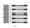
- Fig.4b is a schematic diagram of a sub-carrier based sequence selection scheme with rank3-rank4.
- an orthogonal sequence in a zone where an arrow directed to the left lies is Code index0: [1 1] [1 -1]
- an orthogonal sequence in a zone where an arrow directed to the right lies is Code index1: [1 1] [-1 1].
- this scheme is characterized in that firstly sub-carriers adjacent in a PRB are grouped so that there are three groups per PRB and two corresponding sub-carriers per group; and sequence inversion (selection) is performed per sub-carrier, that is, the same orthogonal sequence set is adopted for sub-carriers in a group and different orthogonal sequence sets are adopted for adjacent groups.
- Fig.4c is a schematic diagram of a sub-carrier group based sequence selection scheme with rank3-rank4.
- an orthogonal sequence for transmission of dedicated pilots in a zone where an arrow directed to the left lies is Code index0: [1 1] [1 -1]
- an orthogonal sequence in a zone where an arrow directed to the right lies is Code index1: [1 1] [-1 1].
- Code index 3 ⁇ PRB_index + ⁇ intrasubcarrier_index / 5 ⁇ ⁇ mod 2
- Fig.4d is a schematic diagram of a PRB based sequence selection scheme with rank3-rank4. As illustrated in Fig.4d , there are two PRBs illustrated in this scheme, where an arrow directed to the left represents an orthogonal sequence of Code index0: [1 1] [1 -1] in a zone for transmission of dedicated pilots in the PRB2, and an arrow directed to the right represents an orthogonal sequence of Code index1: [1 1] [-1 1] in a zone for transmission of dedicated pilots in the PRB1.
- a rule adopted for streams 1 and 2 differs from that for streams 3 and 4: this scheme is characterized in that a frequency-domain granularity at which a sequence is mapped for the streams 1 and 2 is the same as that for the streams 3 and 4, but starting sub-carriers of different groups of ports correspond to different orthogonal sequence sets.
- a starting sub-carrier is the sub-carrier at the lowest frequency among sub-carriers corresponding to a group of ports.
- Fig.4e is a schematic diagram of rank3-rank4 with a sequence mapping rule adopted for streams 1 and 2 differing from that for streams 3 and 4, and as illustrated in Fig.4e , an orthogonal sequence in a zone where an arrow directed to the left lies is Code index0: [1 1] [1 -1], and an orthogonal sequence in a zone where an arrow directed to the right lies is Code index1: [1 1] [-1 1].
- a scheme with rank5-rank8 at the length of an orthogonal sequence being 2 is the same as rank3-rank4 except that respective sequences correspond to different ports.
- Fig.5a illustrates a sub-carrier based orthogonal sequence selection scheme with rank5-rank8 at a length of 4.
- an orthogonal sequence for transmission of dedicated pilots in a zone where an arrow directed to the left lies is Code index0: [1 1 1 1] [1 1 -1 -1][1 -1 -1 1][1 -1 1 -1]; and an orthogonal sequence related to an arrow directed to the right lies is Code index1: [1 1 1 1] [-1 -1 1][1 -1 -1 1][-1 1 -1 1].
- Fig.5b illustrates a sub-carrier group based orthogonal sequence selection scheme with PRB rank5-rank8 at a length of 4: an orthogonal sequence for transmission of dedicated pilots in a zone where an arrow directed to the left lies is Code index0: [1 1 1 1] [1 1 -1 -1] [1 -1 -1 1][1 -1 1 -1]; and an orthogonal sequence in a zone where an arrow directed to the right lies is Code index1: [1 1 1 1] [-1 -1 1 1][1 -1 -1 1][-1 1 -1 1].
- an orthogonal sequence for transmission of dedicated pilots in a zone where an arrow directed to the left lies is Code index0: [1 1] [1 -1]; and an orthogonal sequence in a zone where an arrow directed to the right lies is Code index1: [1 1] [-1 1].
- pilots per four streams correspond to one group of ports and are mapped onto the same resource, and orthogonality between pilot ports in a group of ports is ensured for pilots in the group in the code division mode.
- Different resources are allocated for different groups of ports to ensure orthogonality between pilot ports in the different groups, i.e., the FDM mode.
- resource elements numbered 01 and 23 represent two groups of pilot ports respectively.
- pilots are actually configured with a consistent number of ports with the rank of data.
- a sub-carrier will particularly refer to a sub-carrier for transmission of dedicated pilots
- An orthogonal sequence set of a current sub-carrier is determined according to a predefined orthogonal sequence sets and the sequence number of the sub-carriers.
- a group of ports 1 is configured with orthogonal sequence sets a and b which are alternatively mapped onto corresponding sub-carriers; and a group of ports 2 is configured with orthogonal sequence sets c and d which are alternatively mapped onto corresponding sub-carriers.
- An orthogonal sequence for transmission of dedicated pilots in a zone where an arrow denoted with "a” lies is Code index0: [1 1 1 1] [1 1 -1 -1][1 -1 -1 1][1 -1 1 -1]; an orthogonal sequence for transmission of dedicated pilots in a zone where an arrow denoted with "b” lies is Code index1: [1 1 1 1] [-1 -1 1][1 -1 -1 1][-1 1 -1 1]; an orthogonal sequence for transmission of dedicated pilots in a zone where an arrow denoted with "c” lies is Code index2: [1 1 1 1] [-1 -1 1][-1 1 1 -1][1 -1 1 -1]; and an orthogonal sequence for transmission of dedicated pilots in a zone where an arrow denoted with "d” lies is Code index3: [1 1 1 1] [1 1 -1 -1][-1 1 1 -1][-1 1 -1 1].
- Fig.6b is a sub-carrier group based orthogonal sequence selection scheme with rank5-rank8 at a length of 4.
- an orthogonal sequence for transmission of dedicated pilots in a zone where an arrow denoted with "a” lies is Code index0: [1 1 1 1][1 1 -1 -1][1 -1 -1 1][1 -1 1 -1]; an orthogonal sequence for transmission of dedicated pilots in a zone where an arrow denoted with "b” lies is Code index1: [1 1 1 1] [-1 -1 1][1 -1 -1 1][-1 1 -1 1][-1 1 -1 1]; an orthogonal sequence for transmission of dedicated pilots in a zone where an arrow denoted with "c” lies is Code index2: [1 1 1 1] [-1 -1 1][-1 1 1 -1][1 -1 1 -1]; and an orthogonal sequence for transmission of dedicated pilots in a zone where an arrow denoted with "d”
- Fig.6c is a PRB based orthogonal sequence selection scheme with rank5-rank8 at a length of 4.
- orthogonal sequence inversion selection
- selection may be constant with time or vary from one timeslot (or sub-frame) to another.
- orthogonal sequence inversion (selection) of different cells may be the same or different.
- a specific rank or pilot structure may vary without departing from the solution in the embodiment of the invention.
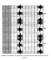
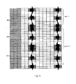
- Fig.7a is sequence selection (or inversion) only in a PRB. Referring to Fig.7a , there is sequence selection (or inversion) only in a PRB. Different sequences are adopted (or sequences are inverted) for different groups of sub-carriers in a PRB, and the same sequence is adopted (or no sequence is inverted) for different PRBs, as illustrated in Fig.7a .
- the sequence adopted in the PRB can be signaled to a user or standard-defined (i.e., defaulted). The user performs channel estimation according to the defaulted or signaled pilot sequences.
- Fig.7b is a schematic diagram of sequence selection (or inversion) in a user scheduled PRB. As illustrated in Fig.7b showing sequence selection (or inversion) in a user scheduled PRB, different sequences are adopted (or sequences are inverted) for adjacent PRBs in a user scheduled resource block. Sequences adopted for a user starting PRB may be standard-defined or broadcast-signaled or DCI signaling-configured; and the base station configures a user with orthogonal pilot sequences according to the sequences adopted in the user starting PRB and an inversion selection (a sequence selection rule). The user performs channel estimation according to the defaulted or signaled pilot sequence.
- Fig.7c is sequence selection (or inversion) over a system bandwidth. Referring to Fig.7c , different sequences are adopted (or sequences are inverted) for adjacent PRBs throughout the system bandwidth. Sequences adopted for a starting PRB of the bandwidth may be standard-defined or broadcast-signaled or DCI signaling-configured.
- the base station configures a user with orthogonal pilot sequences according to the sequences adopted in the starting PRB of the bandwidth and an index value of the PRB.
- the user performs channel estimation according to the pilot sequences adopt at the transmitter.
- An embodiment of the invention provides a system for transmitting downlink data, which includes:
- a base station configured to transmit dedicated pilots in the Code Division Multiplexing (CDM) mode or in hybrid of CDM and Frequency Division Multiplexing (FDM) mode, where the dedicated pilots are configured with orthogonal sequence sets over resources for transmission of the dedicated pilots according to a preset frequency-domain granularity and rule and the same orthogonal sequence set is adopted for the dedicated pilots in each frequency-domain granularity; and
- a user equipment configured to receive the dedicated pilots according to obtained starting PRB orthogonal sequence configuration information, frequency-domain granularity information and rule or configuration information of orthogonal sequence sets, wherein the same orthogonal sequence set is adopted for the dedicated pilots in each frequency-domain granularity.
- an embodiment of the invention provides an apparatus for transmitting downlink data, which is equivalent to the base station in the system and which includes:
- a configuring unit 81 configured to configure dedicated pilots with orthogonal sequence sets over resources for transmission of the dedicated pilots according to a preset frequency-domain granularity and rule by adopting the same orthogonal sequence set for the dedicated pilots per frequency-domain granularity;
- a first transmission unit 82 configured to transmit the dedicated pilots in the Code Division Multiplexing (CDM) mode or in hybrid of CDM and Frequency Division Multiplexing (FDM) mode.
- CDM Code Division Multiplexing
- FDM Frequency Division Multiplexing
- the frequency-domain granularity is a sub-carrier, a group of sub-carriers or a resource block PRB.
- the configuring unit 81 is configured to adopt one orthogonal sequence set for each sub-carrier and different orthogonal sequence sets for adjacent sub-carriers among sub-carriers for transmission of the dedicated pilots in each resource block when the frequency-domain granularity is a sub-carrier.
- the configuring unit 81 is configured to adopt the same orthogonal sequence set in each group of sub-carriers and different orthogonal sequence sets between adjacent groups of sub-carriers among groups of sub-carriers for transmission of the dedicated pilots in each resource block when the frequency-domain granularity is a group of sub-carriers.
- the configuring unit 81 is configured to adopt the same orthogonal sequence set over resources for transmission of the dedicated pilots in each resource block when the frequency-domain granularity is a resource block PRB.
- the configuring unit 81 is configured to configure the dedicated pilots with orthogonal sequence sets according to the orthogonal sequence set and the sub-carrier sequence number, adopted for the starting sub-carrier of a system bandwidth; or
- a second transmitting unit configured to transmit the dedicated pilots with the configured orthogonal sequence sets to a user equipment so as to be provided to the user equipment for channel estimation.
- the second transmitting unit is configured to transmit the configured orthogonal sequence sets in broadcast message or a DCI message.
- an embodiment of the invention provides an apparatus for receiving downlink data, which is equivalent to the user equipment in the system and which includes:
- An obtaining unit 91 configured to obtain starting PRB orthogonal sequence configuration information, frequency-domain granularity information and rule or configuration information of orthogonal sequence sets;
- a receiving unit 92 configured to receive the dedicated pilots according to the obtained starting PRB orthogonal sequence configuration information, frequency-domain granularity information and rule or configuration information of orthogonal sequence sets, where the same orthogonal sequence set is adopted for the dedicated pilots in each frequency-domain granularity.
- the frequency-domain granularity is a sub-carrier, a group of sub-carriers or a resource block PRB.
- the frequency-domain granularity is a sub-carrier
- one orthogonal sequence set is adopted for each sub-carrier and different orthogonal sequence sets are adopted for adjacent sub-carriers among sub-carriers for transmission of the dedicated pilots in each resource block.
- the frequency-domain granularity is a group of sub-carriers
- the same orthogonal sequence set is adopted in each group of sub-carriers and different orthogonal sequence sets are adopted between adjacent groups of sub-carriers among groups of sub-carriers for transmission of the dedicated pilots in each resource block.
- the frequency-domain granularity is a resource block PRB
- the same orthogonal sequence set is adopted over resources for transmission of the dedicated pilots in each resource block.
- the obtaining unit 91 is configured to obtain the orthogonal sequence sets in the dedicated pilots by receiving a broadcast message or a DCI message, transmitted from a base station, including orthogonal sequences, or to obtain the orthogonal sequence sets in the dedicated pilots from dedicated pilot orthogonal sequence information stored in advance, or to generate the orthogonal sequence sets in the dedicated pilots according to a rule stored in advance.
- the dedicated pilots are transmitted over the same sub-carrier in each group of ports in the CDM mode, and a frequency-domain granularity and/or configuration preset for one group of ports is the same as or different from that for another.
- the configuring unit 81 is configured to adopt different orthogonal sequence sets for adjacent sub-carriers for transmission of the dedicated pilots in the same group of ports but different orthogonal sequence sets for starting sub-carriers of different groups of ports.
- the configuring unit 81 is configured to adopt the same orthogonal sequence at data layers of transmission 1 and 3 and an opposite orthogonal sequence at layer 4 to that at layer 2.
- the configuring unit 81 is configured to adopt the same or different frequency-domain granularities and rules for different rank-numbers of system transmission.
- the invention proposes three types of granularity configuration of a pilot orthogonal sequence to thereby facilitate extensions and implementations of various ranks and presents three methods for performing pilot orthogonal sequence selection (or inversion).
- the foregoing embodiments present in details the method for sequence inversion (or selection) with rank3-rank8 and the scheme of PRB based inversion (or selection) with rank2 to lower the complexity of sequence mapping.
- Orthogonal sequence inversion (or selection) does not vary with time or varies from one timeslot (or sub-frame) to another. Orthogonal sequence inversion (or selection) in one cell may be the same as or different from that in another.
- the method for sequence inversion (or selection) addresses the problem of consistent power due to rank3-rank8 orthogonal sequences and is easy to perform.
- the embodiments of the invention can be embodied as a method, system or computer program product. Therefore, the invention can be embodied in the form of an all-hardware embodiment, an all-software embodiment or an embodiment of software and hardware in combination. Furthermore the invention can be embodied in the form of a computer program product embodied in one or more computer useable storage mediums (including but not limited to a disk memory, a CD-ROM, an optical memory, etc.) in which computer useable program codes are contained.
- a computer useable storage mediums including but not limited to a disk memory, a CD-ROM, an optical memory, etc.
- These computer program instructions can also be stored into a computer readable memory capable of directing the computer or the other programmable data processing apparatus to operate in a specific manner so that the instructions stored in the computer readable memory create an article of manufacture including instruction means which perform the functions specified in the flow(s) of the flow chart and/or the block(s) of the block diagram.
- These computer program instructions can also be loaded onto the computer or the other programmable data processing apparatus so that a series of operational steps are performed on the computer or the other programmable data processing apparatus to create a computer implemented process so that the instructions executed on the computer or the other programmable apparatus provide steps for performing the functions specified in the flow(s) of the flow chart and/or the block(s) of the block diagram.
Landscapes
- Engineering & Computer Science (AREA)
- Signal Processing (AREA)
- Computer Networks & Wireless Communication (AREA)
- Power Engineering (AREA)
- Mobile Radio Communication Systems (AREA)
Abstract
Description
- This application claims the benefits of Chinese Patent Applications no.
200910237048.3 200910227799.7 - The present invention relates to the field of communications and particularly to a method, apparatus and system for transmitting downlink pilots.
- The new technologies of High-order Multi-Input Multi-Output (MIMO), multi-cell cooperative transmission, etc., will be adopted in a 3GPP Long Term Evolution (LTE)-Advanced system, i.e., the advancement of an LTE system, which is an evolved system of a third-generation mobile communication system, to improve the performance of the system.
- Dedicated pilots are adopted in the LTE-A system to demodulate data in order to better support the new technologies. A dedicated pilot corresponds to a data stream, and pilots keep orthogonal between respective streams. In a transmission scheme with rank1 and rank2, orthogonality between pilots of the two streams is ensured in the Code Division Multiplexing (CDM) mode; in a transmission scheme with rank3 and rank4, orthogonality between pilots of the four streams is ensured in hybrid of Frequency Division Multiplexing (FDM) and CDM mode; and in a transmission scheme with rank5, rank6, rank7 and rank8, orthogonality between pilots of the eight streams is ensured in hybrid of FDM and CDM mode. As can be apparent, the CDM mode is involved for the pilots in all the transmission schemes. When Walsh codes or a normalized Walsh codes are adopted as pilots in the CDM mode, the power sum of pilots over one Orthogonal Frequency Division Multiplexing (OFDM) symbol may differ from that over another so that the power of one OFDM symbol may differ from that of another.
- The invention provides a method, apparatus and system for transmitting downlink pilots to address the problem in the prior art of different power over different OFDM symbols.
- A method for transmitting downlink pilots according to an embodiment of the invention includes:
- transmitting dedicated pilots in the Code Division Multiplexing, CDM, mode or in hybrid of CDM and Frequency Division Multiplexing, FDM, mode, wherein:
- the dedicated pilots are configured with orthogonal sequence sets over resources for transmission of the dedicated pilots according to a preset frequency-domain granularity and rule and the same orthogonal sequence set is adopted for the dedicated pilots in each frequency-domain granularity.
- A apparatus for transmitting downlink pilots according to an embodiment of the invention includes:
- a configuring unit configured to configure dedicated pilots with orthogonal sequence sets over resources for transmission of the dedicated pilots according to a preset frequency-domain granularity and rule by adopting the same orthogonal sequence set for the dedicated pilots in each frequency-domain granularity; and
- a first transmission unit configured to transmit the dedicated pilots in the Code Division Multiplexing, CDM, mode or in hybrid of CDM and Frequency Division Multiplexing, FDM, mode.
- A method for receiving downlink pilots according to an embodiment of the invention includes:
- receiving dedicated pilots according to obtained starting PRB orthogonal sequence configuration information, frequency-domain granularity information and rule, wherein the same orthogonal sequence set is adopted for the dedicated pilots in each frequency-domain granularity.
- A apparatus for receiving downlink data according to an embodiment of the invention includes:
- an obtaining unit configured to obtain starting PRB orthogonal sequence configuration information, frequency-domain granularity information, rule for receiving dedicated pilots and obtained orthogonal sequence sets; and
- to receive the dedicated pilots according to the obtained starting PRB orthogonal sequence configuration information, frequency-domain granularity information and the rule, wherein the same orthogonal sequence set is adopted for the dedicated pilots in each frequency-domain granularity.
- A system for transmitting downlink data according to an embodiment of the invention includes:
- a base station configured to transmit dedicated pilots in the Code Division Multiplexing, CDM, mode or in hybrid of CDM and Frequency Division Multiplexing, FDM, mode, wherein the dedicated pilots are configured with orthogonal sequence sets over resources for transmission of the dedicated pilots according to a preset frequency-domain granularity and rule and the same orthogonal sequence set is adopted for the dedicated pilots in each frequency-domain granularity; and
- a user equipment configured to receive the dedicated pilots according to obtained starting PRB orthogonal sequence configuration information, frequency-domain granularity information and rule or configuration information of orthogonal sequence sets, wherein the same orthogonal sequence set is adopted for the dedicated pilots in each frequency-domain granularity.
- In the embodiments of the invention, a frequency-domain granularity is preset, and dedicated pilots are transmitted in the Code Division Multiplexing (CDM) mode or in hybrid of CDM and Frequency Division Multiplexing (FDM) mode, wherein the dedicated pilots are configured with orthogonal sequence sets over resources for transmission of the dedicated pilots according to the preset frequency-domain granularity and rule and the same orthogonal sequence set is adopted for the dedicated pilots in each frequency-domain granularity to thereby address the problem of power differences among OFDM symbols caused by Walsh Codes.
-
Fig.1 is a schematic flow chart of a transmitting method according to an embodiment of the invention; -
Fig.2 is a schematic flow chart of a receiving method according to an embodiment of the invention; -
Fig.3a is a schematic diagram of a rank1-rank2 pilot structure; -
Fig.3b is a schematic diagram of resource block PRB based inversion with rank2; -
Fig.4a is a schematic diagram of a rank3-rank4 pilot structure and a rank5-rank8 pilot structure; -
Fig.4b is a schematic diagram of a sub-carrier based sequence selection scheme with rank3-rank4; -
Fig.4c is a schematic diagram of a sub-carrier group based sequence selection scheme with rank3-rank4; -
Fig.4d is a schematic diagram of a PRB based sequence selection scheme with rank3-rank4; -
Fig.4e is a schematic diagram of rank3-rank4 with a sequence mapping rule atlayers layers -
Fig.5a is a sub-carrier based orthogonal sequence selection scheme with rank5-rank8 at a length of 4; -
Fig.5b is a sub-carrier group based orthogonal sequence selection scheme with PRB rank5-rank8 at a length of 4; -
Fig.5c is a PRB based orthogonal sequence selection scheme with rank5-rank8 at a length of 4; -
Fig.6a is a sub-carrier based orthogonal sequence selection scheme with rank5-rank8 at a length of 4; -
Fig.6b is a sub-carrier group based orthogonal sequence selection scheme with rank5-rank8 at a length of 4; -
Fig.6c is a PRB based orthogonal sequence selection scheme with rank5-rank8 at a length of 4; -
Fig.7a is sequence selection (or inversion) only in a PRB; -
Fig.7b is sequence selection (or inversion) in a user scheduled resource block; -
Fig.7c is sequence selection (or inversion) over a system bandwidth; -
Fig.8 is a schematic structural diagram of a transmitting apparatus according to an embodiment of the invention; and -
Fig.9 is a schematic structural diagram of a receiving apparatus according to an embodiment of the invention - In order to address the problem that power of one OFDM symbol may differ from that of another due to a Walsh code, dedicated pilots are transmitted in the Code Division Multiplexing (CDM) mode or in hybrid of CDM and Frequency Division Multiplexing (FDM) mode in the embodiments of the invention, where dedicated pilots are configured with orthogonal sequence sets over resources for transmission of the dedicated pilots according to a preset frequency-domain granularity and rule and the same orthogonal sequence set is adopted for the dedicated pilots in each frequency-domain granularity.
- Referring to
Fig.1 , a method for transmitting downlink pilots according to an embodiment of the invention includes: - In the
step 101, dedicated pilots are mapped in the Code Division Multiplexing (CDM) mode or in hybrid of CDM and Frequency Division Multiplexing (FDM) mode, where the dedicated pilots are configured with orthogonal sequence sets over resources for transmission of the dedicated pilots according to a preset frequency-domain granularity and rule and the same orthogonal sequence set is adopted for the dedicated pilots in each frequency-domain granularity. - In the
step 102, the mapped dedicated pilots are transmitted. - The frequency-domain granularity is a sub-carrier, a group of sub-carriers or a resource block PRB.
- When the frequency-domain granularity is a sub-carrier, one orthogonal sequence set is adopted for each sub-carrier and different orthogonal sequence sets are adopted for adjacent sub-carriers among sub-carriers for transmission of the dedicated pilots in each resource block.
- When the frequency-domain granularity is a group of sub-carriers, the same orthogonal sequence set is adopted in each group of sub-carriers and different orthogonal sequence sets are adopted between adjacent groups of sub-carriers among groups of sub-carriers for transmission of the dedicated pilots in each resource block.
- When the frequency-domain granularity is a resource block PRB, the same orthogonal sequence set is adopted over the resource for transmission of the dedicated pilots in each resource block.
- The dedicated pilots are configured with orthogonal sequence sets according to the preset rule as follows:
- The dedicated pilots are configured with orthogonal sequence sets according to the orthogonal sequence set adopted for the starting PRB of a system bandwidth; or the dedicated pilots are configured with orthogonal sequence sets according to the orthogonal sequence set and the resource block scheduling sequence number, adopted for the starting PRB scheduled by user.
- The dedicated pilots with the configured orthogonal sequence sets are transmitted to a user equipment so as to be provided to the user equipment for channel estimation.
- When there is more than one group of ports and each group of ports corresponds to more than one sub-carrier, the dedicated pilots are transmitted over the same sub-carrier in each group of ports in the CDM mode, and a frequency-domain granularity and/or a rule preset for one group of ports may be the same as or different from that for another. A frequency-domain granularity and/or a rule preset for one rank-number of system transmission may be the same as or different from that for another. When different groups of ports correspond to a frequency-domain granularity which is a sub-carrier, different orthogonal sequence sets are adopted for adjacent sub-carriers for transmission of the dedicated pilots in the same group of ports, but different orthogonal sequence sets are adopted for starting sub-carriers of different groups of ports. For example, when a rank-number of system transmission is 3 or 4, the same orthogonal sequence is adopted at data layers of
transmission layer 4 is opposite to that atlayer 2. - In the
step 102, the dedicated pilots with the configured orthogonal sequence sets are transmitted to a user equipment so as to be provided to the user equipment for channel estimation. In a specific implementation, the configured orthogonal sequence sets can be transmitted to the user equipment in a broadcast message or Downlink Control Information (DCI). Of course, the orthogonal sequence sets may be not transmitted but, for example, stored in advance at the user equipment. - Referring to
Fig.2 , a method for receiving downlink pilots according to an embodiment of the invention includes the following steps: - The
step 201 is to obtain starting PRB orthogonal sequence configuration information, frequency-domain granularity information and rule or configuration information of orthogonal sequence sets. - The starting PRB resource configuration information, the frequency-domain granularity information and the rule may be configured in advance at the user equipment or updated with configuration information periodically received from the network.
- The orthogonal sequence sets in the dedicated pilots may be obtained by receiving a broadcast message or a DCI message, transmitted from the base station, including orthogonal sequences, or the orthogonal sequence sets in the dedicated pilots may be stored in advance at the user equipment, or the orthogonal sequence sets in the dedicated pilots may be generated by the user equipment according to a rule stored in advance.
- The
step 202 is to receive the dedicated pilots according to the obtained starting PRB resource configuration information, frequency-domain granularity information and rule and the obtained orthogonal sequence sets, where the same orthogonal sequence set is adopted for the dedicated pilots in each frequency-domain granularity. - In correspondence to the transmitting method illustrated in
Fig.1 , the frequency-domain granularity as referred here to may also be a sub-carrier, a group of sub-carriers or a resource block PRB. A specific granularity in use may be preset by the system or adjusted dependent upon a condition of resources. - When the frequency-domain granularity is a sub-carrier, one orthogonal sequence set is adopted for each sub-carrier and different orthogonal sequence sets are adopted for adjacent sub-carriers among sub-carriers for transmission of the dedicated pilots in each resource block.
- When the frequency-domain granularity is a group of sub-carriers, the same orthogonal sequence set is adopted in each group of sub-carriers and different orthogonal sequence sets are adopted between adjacent groups of sub-carriers among groups of sub-carriers for transmission of the dedicated pilots in each resource block.
- When the frequency-domain granularity is a resource block PRB, the same orthogonal sequence set is adopted over resources for transmission of the dedicated pilots in each resource block.
- In an embodiment of the invention, sub-carrier based and sub-carrier group based schemes are identical with rank1-rank2.
-
Fig.3a is a schematic diagram of an LTE-A downlink dedicated pilot structure. Dedicated pilots are transmitted in the 2nd, the 7th and the 12th sub-carriers inOFDM symbols dedicated pilot ports Fig.3a as an example, and this illustrated scheme will not be limited to any transmission mode. -
Fig.3b is a schematic diagram of PRB based inversion with rank2. In this illustrated scheme, the horizontal axis represents time while the vertical axis represents frequency, the illustrated frame structure includes two PRBs with a shadowed zone representing a zone for transmission of dedicated pilots, and orthogonal sequence inversion (selection) can be performed per PRB, that is, orthogonal sequences of adjacent PRBs are different and the same orthogonal sequence applies in a PRB in the frequency domain. As illustrated inFig.3b , an arrow directed to the left represents a sequence [1 1; 1 -1] adopted in a corresponding zone for transmission of dedicated pilots in the PRB2 (the invention will not be limited to this sequence which is merely illustrative, and the same will apply hereinafter); and an arrow directed to the right represents [1 1; -1 1] adopted in thePRB 1. - The index of an orthogonal sequence can be calculated in the formula of Code index=
PRB_ index mod 2. - The technical solution of the invention will be described below taking a rank3-rank4 pilot structure as an example.
- Referring to
Fig.4a , the rank3-rank4 pilot structure results from increasing the number of supported ports in the frequency division (FDM) mode based upon rank1-rank2, and as illustrated inFig.4a , 23 corresponds toports ports ports OFDM symbols dedicated pilot ports dedicated pilot ports - Based upon the characteristic of the rank3-rank4 pilot structure, there are three general modes for orthogonal sequence group inversion (selection): per sub-carrier, per group of sub-carriers and per PRB, where each mode is implemented in two methods: orthogonal sequences are set for all the ports according to a uniform frequency granularity and rule; and orthogonal sequences are set for different ports or different groups of ports according to different frequency granularities and rules.
- (1) Per sub-carrier: this scheme is characterized in different orthogonal sequence sets of adjacent sub-carriers.
-
Fig.4b is a schematic diagram of a sub-carrier based sequence selection scheme with rank3-rank4. As illustrated inFig.4b , an orthogonal sequence in a zone where an arrow directed to the left lies is Code index0: [1 1] [1 -1], and an orthogonal sequence in a zone where an arrow directed to the right lies is Code index1: [1 1] [-1 1]. The index of an orthogonal sequence can be calculated in one of the formulas of:


- (2) Per group of sub-carriers: this scheme is characterized in that firstly sub-carriers adjacent in a PRB are grouped so that there are three groups per PRB and two corresponding sub-carriers per group; and sequence inversion (selection) is performed per sub-carrier, that is, the same orthogonal sequence set is adopted for sub-carriers in a group and different orthogonal sequence sets are adopted for adjacent groups.
Fig.4c is a schematic diagram of a sub-carrier group based sequence selection scheme with rank3-rank4. As illustrated inFig.4c , an orthogonal sequence for transmission of dedicated pilots in a zone where an arrow directed to the left lies is Code index0: [1 1] [1 -1], and an orthogonal sequence in a zone where an arrow directed to the right lies is Code index1: [1 1] [-1 1]. The index of an orthogonal sequence can be calculated in one of the formulas of:

- (3) Per PRB: this scheme is characterized in different orthogonal sequence sets over adjacent PRBs.
Fig.4d is a schematic diagram of a PRB based sequence selection scheme with rank3-rank4. As illustrated inFig.4d , there are two PRBs illustrated in this scheme, where an arrow directed to the left represents an orthogonal sequence of Code index0: [1 1] [1 -1] in a zone for transmission of dedicated pilots in the PRB2, and an arrow directed to the right represents an orthogonal sequence of Code index1: [1 1] [-1 1] in a zone for transmission of dedicated pilots in the PRB1. The index of an orthogonal sequence can be calculated in the formula of:
- (4) A rule adopted for
streams streams 3 and 4: this scheme is characterized in that a frequency-domain granularity at which a sequence is mapped for thestreams streams Fig.4e is a schematic diagram of rank3-rank4 with a sequence mapping rule adopted forstreams streams Fig.4e , an orthogonal sequence in a zone where an arrow directed to the left lies is Code index0: [1 1] [1 -1], and an orthogonal sequence in a zone where an arrow directed to the right lies is Code index1: [1 1] [-1 1]. - The technical solution of the invention will be described below taking a rank5-rank8 pilot structure as an example.
- A scheme with rank5-rank8 at the length of an orthogonal sequence being 2 is the same as rank3-rank4 except that respective sequences correspond to different ports.
- At the length of an orthogonal sequence being 4, there are two categories dependent upon a group of sequences in use: 1 of 2 sequences (merely sequence inversion) and 1 of 4 sequences, which will be described below:
- In the first category, there are three specific modes for 1 of 2 sequences: per sub-carrier, per group of sub-carriers and per PRB.
-
Fig.5a illustrates a sub-carrier based orthogonal sequence selection scheme with rank5-rank8 at a length of 4. - Referring to
Fig.5a , in the sub-carrier based mode, an orthogonal sequence for transmission of dedicated pilots in a zone where an arrow directed to the left lies is Code index0: [1 1 1 1] [1 1 -1 -1][1 -1 -1 1][1 -1 1 -1]; and an orthogonal sequence related to an arrow directed to the right lies is Code index1: [1 1 1 1] [-1 -1 1 1][1 -1 -1 1][-1 1 -1 1]. - The index of an orthogonal sequence can be calculated in one of the formulas of:


- (2)
Fig.5b illustrates a sub-carrier group based orthogonal sequence selection scheme with PRB rank5-rank8 at a length of 4: an orthogonal sequence for transmission of dedicated pilots in a zone where an arrow directed to the left lies is Code index0: [1 1 1 1] [1 1 -1 -1] [1 -1 -1 1][1 -1 1 -1]; and an orthogonal sequence in a zone where an arrow directed to the right lies is Code index1: [1 1 1 1] [-1 -1 1 1][1 -1 -1 1][-1 1 -1 1]. - The index of an orthogonal sequence can be calculated in one of the formulas of:


- (3) Referring to
Fig.5c , in a PRB based orthogonal sequence selection scheme with rank5-rank8 at a length of 4, an orthogonal sequence for transmission of dedicated pilots in a zone where an arrow directed to the left lies is Code index0: [1 1] [1 -1]; and an orthogonal sequence in a zone where an arrow directed to the right lies is Code index1: [1 1] [-1 1]. - The index of an orthogonal sequence can be calculated in the formula of:

- In the second category, there are three specific modes for 1 of 4 sequences: per sub-carrier, per group of sub-carriers and per PRB.
- (1) Per sub-carrier:
- In a transmission scheme with rank5, rank6, rank7 and rank8, orthogonality of pilots is ensured in hybrid of FDM and CDM mode as illustrated in
Fig.4a . Pilots per four streams correspond to one group of ports and are mapped onto the same resource, and orthogonality between pilot ports in a group of ports is ensured for pilots in the group in the code division mode. Different resources are allocated for different groups of ports to ensure orthogonality between pilot ports in the different groups, i.e., the FDM mode. As illustrated inFig.4a , resource elements numbered 01 and 23 represent two groups of pilot ports respectively. Furthermore pilots are actually configured with a consistent number of ports with the rank of data. - In the transmission scheme with rank5, rank6, rank7 and rank8, orthogonal sequences of pilots are mapped in the following method:
- 1) Different orthogonal sequence sets are adopted for starting sub-carriers for transmission of dedicated pilots in different groups of ports (hereinafter a sub-carrier will particularly refer to a sub-carrier for transmission of dedicated pilots);
- (2) Different orthogonal sequence sets are adopted for adjacent sub-carriers in the same group of ports, for example, one group of ports is configured with two orthogonal sequence sets which are alternatively mapped; and
- (3) An orthogonal sequence set of a current sub-carrier is determined according to a predefined orthogonal sequence sets and the sequence number of the sub-carriers.
- As illustrated in
Fig.6a , a group ofports 1 is configured with orthogonal sequence sets a and b which are alternatively mapped onto corresponding sub-carriers; and a group ofports 2 is configured with orthogonal sequence sets c and d which are alternatively mapped onto corresponding sub-carriers. - An orthogonal sequence for transmission of dedicated pilots in a zone where an arrow denoted with "a" lies is Code index0: [1 1 1 1] [1 1 -1 -1][1 -1 -1 1][1 -1 1 -1]; an orthogonal sequence for transmission of dedicated pilots in a zone where an arrow denoted with "b" lies is Code index1: [1 1 1 1] [-1 -1 1 1][1 -1 -1 1][-1 1 -1 1]; an orthogonal sequence for transmission of dedicated pilots in a zone where an arrow denoted with "c" lies is Code index2: [1 1 1 1] [-1 -1 1 1][-1 1 1 -1][1 -1 1 -1]; and an orthogonal sequence for transmission of dedicated pilots in a zone where an arrow denoted with "d" lies is Code index3: [1 1 1 1] [1 1 -1 -1][-1 1 1 -1][-1 1 -1 1].

- The corresponding sets of sequences of a, b, c and d will not be limited to the foregoing sets of sequences, and alike the method for calculating code_index will not be limited thereto.
- (2) Per group of sub-carriers:
-
Fig.6b is a sub-carrier group based orthogonal sequence selection scheme with rank5-rank8 at a length of 4. Referring toFig.6b , an orthogonal sequence for transmission of dedicated pilots in a zone where an arrow denoted with "a" lies is Code index0: [1 1 1 1][1 1 -1 -1][1 -1 -1 1][1 -1 1 -1]; an orthogonal sequence for transmission of dedicated pilots in a zone where an arrow denoted with "b" lies is Code index1: [1 1 1 1] [-1 -1 1 1][1 -1 -1 1][-1 1 -1 1]; an orthogonal sequence for transmission of dedicated pilots in a zone where an arrow denoted with "c" lies is Code index2: [1 1 1 1] [-1 -1 1 1][-1 1 1 -1][1 -1 1 -1]; and an orthogonal sequence for transmission of dedicated pilots in a zone where an arrow denoted with "d" lies is Code index3: [1 1 1 1] [1 1 -1 -1][-1 1 1 -1][-1 1 -1 1]. - (3) Per PRB:
-
Fig.6c is a PRB based orthogonal sequence selection scheme with rank5-rank8 at a length of 4. Referring toFig.6c , an orthogonal sequence for transmission of dedicated pilots in a zone where an arrow denoted with "a" lies is Code index0: [1 1 1 1] [1 1 -1 -1][1 -1 -1 1][1 -1 1 -1]; an orthogonal sequence for transmission of dedicated pilots in a zone where an arrow denoted with "b" lies is Code index1: [1 1 1 1] [-1 -1 1 1][1 -1 -1 1][-1 1 -1 1]; an orthogonal sequence for transmission of dedicated pilots in a zone where an arrow denoted with "c" lies is Code index2: [1 1 1 1] [-1 -1 1 1][-1 1 1 -1][1 -1 1 -1]; and an orthogonal sequence for transmission of dedicated pilots in a zone where an arrow denoted with "d" lies is Code index3: [1 1 1 1] [1 1 -1 -1][-1 1 1 -1][-1 1 -1 1]. - The index of an orthogonal sequence can be calculated in the formula of:
Code index= PRB_index mod 4 - The foregoing embodiment address the issue of orthogonal sequence inversion (selection) at a moment of time in a cell, but orthogonal sequence inversion (selection) may be constant with time or vary from one timeslot (or sub-frame) to another. In view of randomized inter-cell interference, orthogonal sequence inversion (selection) of different cells may be the same or different. Furthermore a specific rank or pilot structure may vary without departing from the solution in the embodiment of the invention.
- An implementation of the embodiment of the invention will be detailed below in several specific embodiments.
- The embodiments will be described taking rank=4 and a sequence selection granularity being a group of sub-carriers as an example, but the invention will not be limited thereto, and the following implementation will be applicable to any sequence selection granularity and any transmission rank (i.e., a configured rank).
- The First Embodiment:
-
Fig.7a is sequence selection (or inversion) only in a PRB. Referring toFig.7a , there is sequence selection (or inversion) only in a PRB. Different sequences are adopted (or sequences are inverted) for different groups of sub-carriers in a PRB, and the same sequence is adopted (or no sequence is inverted) for different PRBs, as illustrated inFig.7a . The sequence adopted in the PRB can be signaled to a user or standard-defined (i.e., defaulted). The user performs channel estimation according to the defaulted or signaled pilot sequences. - The Second Embodiment:
-
Fig.7b is a schematic diagram of sequence selection (or inversion) in a user scheduled PRB. As illustrated inFig.7b showing sequence selection (or inversion) in a user scheduled PRB, different sequences are adopted (or sequences are inverted) for adjacent PRBs in a user scheduled resource block. Sequences adopted for a user starting PRB may be standard-defined or broadcast-signaled or DCI signaling-configured; and the base station configures a user with orthogonal pilot sequences according to the sequences adopted in the user starting PRB and an inversion selection (a sequence selection rule). The user performs channel estimation according to the defaulted or signaled pilot sequence. - The Third Embodiment:
-
Fig.7c is sequence selection (or inversion) over a system bandwidth. Referring toFig.7c , different sequences are adopted (or sequences are inverted) for adjacent PRBs throughout the system bandwidth. Sequences adopted for a starting PRB of the bandwidth may be standard-defined or broadcast-signaled or DCI signaling-configured. The base station configures a user with orthogonal pilot sequences according to the sequences adopted in the starting PRB of the bandwidth and an index value of the PRB. The user performs channel estimation according to the pilot sequences adopt at the transmitter.
An embodiment of the invention provides a system for transmitting downlink data, which includes: - A base station configured to transmit dedicated pilots in the Code Division Multiplexing (CDM) mode or in hybrid of CDM and Frequency Division Multiplexing (FDM) mode, where the dedicated pilots are configured with orthogonal sequence sets over resources for transmission of the dedicated pilots according to a preset frequency-domain granularity and rule and the same orthogonal sequence set is adopted for the dedicated pilots in each frequency-domain granularity; and
- A user equipment configured to receive the dedicated pilots according to obtained starting PRB orthogonal sequence configuration information, frequency-domain granularity information and rule or configuration information of orthogonal sequence sets, wherein the same orthogonal sequence set is adopted for the dedicated pilots in each frequency-domain granularity.
- Referring to
Fig.8 , an embodiment of the invention provides an apparatus for transmitting downlink data, which is equivalent to the base station in the system and which includes: - A configuring unit 81 configured to configure dedicated pilots with orthogonal sequence sets over resources for transmission of the dedicated pilots according to a preset frequency-domain granularity and rule by adopting the same orthogonal sequence set for the dedicated pilots per frequency-domain granularity; and
- A
first transmission unit 82 configured to transmit the dedicated pilots in the Code Division Multiplexing (CDM) mode or in hybrid of CDM and Frequency Division Multiplexing (FDM) mode. - The frequency-domain granularity is a sub-carrier, a group of sub-carriers or a resource block PRB.
- The configuring unit 81 is configured to adopt one orthogonal sequence set for each sub-carrier and different orthogonal sequence sets for adjacent sub-carriers among sub-carriers for transmission of the dedicated pilots in each resource block when the frequency-domain granularity is a sub-carrier.
- The configuring unit 81 is configured to adopt the same orthogonal sequence set in each group of sub-carriers and different orthogonal sequence sets between adjacent groups of sub-carriers among groups of sub-carriers for transmission of the dedicated pilots in each resource block when the frequency-domain granularity is a group of sub-carriers.
- The configuring unit 81 is configured to adopt the same orthogonal sequence set over resources for transmission of the dedicated pilots in each resource block when the frequency-domain granularity is a resource block PRB.
- The configuring unit 81 is configured to configure the dedicated pilots with orthogonal sequence sets according to the orthogonal sequence set and the sub-carrier sequence number, adopted for the starting sub-carrier of a system bandwidth; or
- to configure the dedicated pilots with orthogonal sequence sets according to the orthogonal sequence set and the sub-carriers group sequence number, adopted for the starting group of sub-carriers of a system bandwidth; or
- to configure the dedicated pilots with orthogonal sequence sets according to the orthogonal sequence set and the resource block sequence number, adopted for the starting PRB of a system bandwidth; or
- to configure the dedicated pilots with orthogonal sequence sets according to the orthogonal sequence set and the sub-carrier sequence number, adopted for the starting sub-carrier of user scheduling; or
- to configure the dedicated pilots with orthogonal sequence sets according to the orthogonal sequence set and the sub-carrier group sequence number, adopted for the starting group of sub-carriers of user scheduling; or
- to configure the dedicated pilots with orthogonal sequence sets according to the orthogonal sequence set and the resource block sequence number, adopted for the starting PRB of user scheduling.
- The apparatus for transmitting downlink data according to an embodiment of the invention can further include:
- A second transmitting unit configured to transmit the dedicated pilots with the configured orthogonal sequence sets to a user equipment so as to be provided to the user equipment for channel estimation.
- The second transmitting unit is configured to transmit the configured orthogonal sequence sets in broadcast message or a DCI message.
- Referring to
Fig.9 , an embodiment of the invention provides an apparatus for receiving downlink data, which is equivalent to the user equipment in the system and which includes: - An obtaining
unit 91 configured to obtain starting PRB orthogonal sequence configuration information, frequency-domain granularity information and rule or configuration information of orthogonal sequence sets; and - A receiving
unit 92 configured to receive the dedicated pilots according to the obtained starting PRB orthogonal sequence configuration information, frequency-domain granularity information and rule or configuration information of orthogonal sequence sets, where the same orthogonal sequence set is adopted for the dedicated pilots in each frequency-domain granularity. - The frequency-domain granularity is a sub-carrier, a group of sub-carriers or a resource block PRB.
- When the frequency-domain granularity is a sub-carrier, one orthogonal sequence set is adopted for each sub-carrier and different orthogonal sequence sets are adopted for adjacent sub-carriers among sub-carriers for transmission of the dedicated pilots in each resource block.
- When the frequency-domain granularity is a group of sub-carriers, the same orthogonal sequence set is adopted in each group of sub-carriers and different orthogonal sequence sets are adopted between adjacent groups of sub-carriers among groups of sub-carriers for transmission of the dedicated pilots in each resource block.
- When the frequency-domain granularity is a resource block PRB, the same orthogonal sequence set is adopted over resources for transmission of the dedicated pilots in each resource block.
- The obtaining
unit 91 is configured to obtain the orthogonal sequence sets in the dedicated pilots by receiving a broadcast message or a DCI message, transmitted from a base station, including orthogonal sequences, or to obtain the orthogonal sequence sets in the dedicated pilots from dedicated pilot orthogonal sequence information stored in advance, or to generate the orthogonal sequence sets in the dedicated pilots according to a rule stored in advance. - When there is more than one group of ports and each group of ports corresponds to more than one sub-carrier, the dedicated pilots are transmitted over the same sub-carrier in each group of ports in the CDM mode, and a frequency-domain granularity and/or configuration preset for one group of ports is the same as or different from that for another.
- When different groups of ports correspond to a frequency-domain granularity which is a sub-carrier, the configuring unit 81 is configured to adopt different orthogonal sequence sets for adjacent sub-carriers for transmission of the dedicated pilots in the same group of ports but different orthogonal sequence sets for starting sub-carriers of different groups of ports.
- When a rank-number of system transmission is 3 or 4, the configuring unit 81 is configured to adopt the same orthogonal sequence at data layers of
transmission layer 4 to that atlayer 2. - The configuring unit 81 is configured to adopt the same or different frequency-domain granularities and rules for different rank-numbers of system transmission.
- The invention proposes three types of granularity configuration of a pilot orthogonal sequence to thereby facilitate extensions and implementations of various ranks and presents three methods for performing pilot orthogonal sequence selection (or inversion). The foregoing embodiments present in details the method for sequence inversion (or selection) with rank3-rank8 and the scheme of PRB based inversion (or selection) with rank2 to lower the complexity of sequence mapping. Orthogonal sequence inversion (or selection) does not vary with time or varies from one timeslot (or sub-frame) to another. Orthogonal sequence inversion (or selection) in one cell may be the same as or different from that in another. The method for sequence inversion (or selection) addresses the problem of consistent power due to rank3-rank8 orthogonal sequences and is easy to perform.
- Those skilled in the art shall appreciate that the embodiments of the invention can be embodied as a method, system or computer program product. Therefore, the invention can be embodied in the form of an all-hardware embodiment, an all-software embodiment or an embodiment of software and hardware in combination. Furthermore the invention can be embodied in the form of a computer program product embodied in one or more computer useable storage mediums (including but not limited to a disk memory, a CD-ROM, an optical memory, etc.) in which computer useable program codes are contained.
- The invention has been described in a flow chart and/or a block diagram of the method, the apparatus (system) and the computer program product according to the embodiments of the invention. It shall be appreciated that respective flows and/or blocks in the flow chart and/or the block diagram and combinations of the flows and/or the blocks in the flow chart and/or the block diagram can be embodied in computer program instructions. These computer program instructions can be loaded onto a general-purpose computer, a specific-purpose computer, an embedded processor or a processor of another programmable data processing apparatus to produce a machine so that the instructions executed on the computer or the processor of the other programmable data processing apparatus create means for performing the functions specified in the flow(s) of the flow chart and/or the block(s) of the block diagram.
- These computer program instructions can also be stored into a computer readable memory capable of directing the computer or the other programmable data processing apparatus to operate in a specific manner so that the instructions stored in the computer readable memory create an article of manufacture including instruction means which perform the functions specified in the flow(s) of the flow chart and/or the block(s) of the block diagram.
- These computer program instructions can also be loaded onto the computer or the other programmable data processing apparatus so that a series of operational steps are performed on the computer or the other programmable data processing apparatus to create a computer implemented process so that the instructions executed on the computer or the other programmable apparatus provide steps for performing the functions specified in the flow(s) of the flow chart and/or the block(s) of the block diagram.
- Although the preferred embodiments of the invention have been described, those skilled in the art benefiting from the underlying inventive concept can make additional modifications and variations to these embodiments. Therefore the appended claims are intended to be construed as encompassing the preferred embodiments and all the modifications and variations coming into the scope of the invention.
- Evidently those skilled in the art can make various modifications and variations to the invention without departing from the spirit and scope of the invention. Thus the invention is also intended to encompass these modifications and variations thereto so long as the modifications and variations come into the scope of the claims appended to the invention and their equivalents.
Claims (25)
- A method for transmitting downlink pilots, including the steps of:transmitting dedicated pilots in the Code Division Multiplexing, CDM, mode or in hybrid of CDM and Frequency Division Multiplexing, FDM, mode, wherein:the dedicated pilots are configured with orthogonal sequence sets over resources for transmission of the dedicated pilots according to a preset frequency-domain granularity and rule and the same orthogonal sequence set is adopted for the dedicated pilots in each frequency-domain granularity.
- The method according to claim 1, wherein the frequency-domain granularity is a sub-carrier or a group of sub-carriers.
- The method according to claim 1, wherein when there is more than one group of ports and each group of ports corresponds to more than one sub-carrier, the dedicated pilots are transmitted over the same sub-carrier in each group of ports in the CDM mode, and a frequency-domain granularity and/or a rule preset for one group of ports is the same as or different from that for another.
- The method according to claim 3, wherein when different groups of ports correspond to a frequency-domain granularity which is a sub-carrier, different orthogonal sequence sets are adopted for adjacent sub-carriers for transmission of the dedicated pilots in the same group of ports, and different orthogonal sequence sets are adopted for starting sub-carriers of different groups of ports.
- The method according to claim 4, wherein when a rank-number of system transmission is 3 or 4, the same orthogonal sequence is adopted at data layers of transmission 1 and 3, and an orthogonal sequence at layer 4 is opposite to that at layer 2.
- The method according to claim 4, wherein two orthogonal sequence sets are configured in the same group of ports and alternatively mapped onto sub-carriers for transmission of the dedicated pilots.
- The method according to claim 3, wherein a frequency-domain granularity and/or a rule preset for one rank-number of system transmission is the same as or different from that for another.
- The method according to claim 2, wherein when the frequency-domain granularity is a sub-carrier, one orthogonal sequence set is adopted for each sub-carrier and different orthogonal sequence sets are adopted for adjacent sub-carriers among sub-carriers for transmission of the dedicated pilots in each resource block.
- The method according to claim 2, wherein when the frequency-domain granularity is a group of sub-carriers, the same orthogonal sequence set is adopted in each group of sub-carriers and different orthogonal sequence sets are adopted between adjacent groups of sub-carriers among groups of sub-carriers for transmission of the dedicated pilots in each resource block.
- The method according to claim 1, wherein configuring the dedicated pilots with orthogonal sequence sets according to the preset rule comprises:configuring the dedicated pilots with orthogonal sequence sets according to an orthogonal sequence set and a sub-carrier sequence number, adopted for a starting sub-carrier of a system bandwidth; orconfiguring the dedicated pilots with orthogonal sequence sets according to an orthogonal sequence set and a sub-carrier group sequence number, adopted for a starting group of sub-carriers of a system bandwidth.
- The method according to claim 1, wherein the dedicated pilots are transmitted in the Code Division Multiplexing, CDM, mode or in hybrid of CDM and Frequency Division Multiplexing, FDM, mode, and the method further comprises:transmitting the dedicated pilots with the configured orthogonal sequence sets to a user equipment so as to be provided to the user equipment for channel estimation
- An apparatus for transmitting downlink pilots, comprising:a configuring unit configured to configure dedicated pilots with orthogonal sequence sets over resources for transmission of the dedicated pilots according to a preset frequency-domain granularity and rule by adopting the same orthogonal sequence set for the dedicated pilots in each frequency-domain granularity; anda first transmission unit configured to transmit the dedicated pilots in the Code Division Multiplexing, CDM, mode or in hybrid of CDM and Frequency Division Multiplexing, FDM, mode.
- The apparatus according to claim 12, wherein the frequency-domain granularity is a sub-carrier or a group of sub-carriers.
- The apparatus according to claim 13, wherein the configuring unit is configured to adopt one orthogonal sequence set for each sub-carrier and different orthogonal sequence sets for adjacent sub-carriers among sub-carriers for transmission of the dedicated pilots in each resource block when the frequency-domain granularity is a sub-carrier.
- The apparatus according to claim 13, wherein the configuring unit is configured to adopt the same orthogonal sequence set in each group of sub-carriers and different orthogonal sequence sets between adjacent groups of sub-carriers among groups of sub-carriers for transmission of the dedicated pilots in each resource block when the frequency-domain granularity is a group of sub-carriers.
- The apparatus according to claim 12, wherein the configuring unit is configured to configure the dedicated pilots with orthogonal sequence sets according to an orthogonal sequence set and a sub-carrier sequence number, adopted for a starting sub-carrier of a system bandwidth; or
to configure the dedicated pilots with orthogonal sequence sets according to an orthogonal sequence set and a sub-carriers group sequence number, adopted for a starting group of sub-carriers of a system bandwidth - The apparatus according to claim 12, further comprising a second transmitting unit configured to transmit the dedicated pilots with the configured orthogonal sequence sets to a user equipment so as to be provided to the user equipment for channel estimation.
- The apparatus according to claim 12, wherein when there is more than one group of ports and each group of ports corresponds to more than one sub-carrier, the dedicated pilots are transmitted over the same sub-carrier in each group of ports in the CDM mode, and a frequency-domain granularity preset for one group of ports is the same as or different from that for another.
- The apparatus according to claim 18, wherein when different groups of ports correspond to a frequency-domain granularity which is a sub-carrier, the configuring unit is configured to adopt different orthogonal sequence sets for adjacent sub-carriers for transmission of the dedicated pilots in the same group of ports and different orthogonal sequence sets for starting sub-carriers of different groups of ports.
- The apparatus according to claim 19, wherein when a rank-number of system transmission is 3 or 4, the configuring unit is configured to adopt the same orthogonal sequence at data layers of transmission 1 and 3 and an opposite orthogonal sequence at a layer 4 to that at a layer 2.
- The apparatus according to claim 19, wherein two orthogonal sequence sets are configured in the same group of ports and alternatively mapped onto sub-carriers for transmission of the dedicated pilots.
- The apparatus according to claim 12, wherein the configuring unit is configured to adopt the same or different frequency-domain granularities and rules for different rank-numbers of system transmission.
- A method for receiving downlink pilots, comprising the steps of:receiving dedicated pilots according to obtained starting PRB orthogonal sequence configuration information, frequency-domain granularity information and rule, wherein the same orthogonal sequence set is adopted for the dedicated pilots in each frequency-domain granularity.
- An apparatus for receiving downlink pilots, comprising:an obtaining unit configured to obtain starting PRB orthogonal sequence configuration information, frequency-domain granularity information and rule or configuration information of orthogonal sequence sets; anda receiving unit configured to receive the dedicated pilots according to the obtained starting PRB orthogonal sequence configuration information, frequency-domain granularity information and the rule or configuration information of orthogonal sequence sets, wherein the same orthogonal sequence set is adopted for the dedicated pilots in each frequency-domain granularity.
- A system for transmitting downlink pilots, comprising:a base station configured to transmit dedicated pilots in the Code Division Multiplexing, CDM, mode or in hybrid of CDM and Frequency Division Multiplexing, FDM, mode, wherein the dedicated pilots are configured with orthogonal sequence sets over resources for transmission of the dedicated pilots according to a preset frequency-domain granularity and rule and the same orthogonal sequence set is adopted for the dedicated pilots in each frequency-domain granularity; anda user equipment configured to receive the dedicated pilots according to obtained starting PRB orthogonal sequence configuration information, frequency-domain granularity information and rule or configuration information of orthogonal sequence sets, wherein the same orthogonal sequence set is adopted for the dedicated pilots in each frequency-domain granularity.
Applications Claiming Priority (3)
| Application Number | Priority Date | Filing Date | Title |
|---|---|---|---|
| CN200910237048 | 2009-11-02 | ||
| CN2009102277997A CN102014099B (en) | 2009-11-02 | 2009-12-31 | Downlink pilot frequency transmission method, device and system |
| PCT/CN2010/001747 WO2011050589A1 (en) | 2009-11-02 | 2010-11-01 | Method, apparatus and system for downlink pilot transmission |
Publications (3)
| Publication Number | Publication Date |
|---|---|
| EP2498409A1 true EP2498409A1 (en) | 2012-09-12 |
| EP2498409A4 EP2498409A4 (en) | 2013-07-17 |
| EP2498409B1 EP2498409B1 (en) | 2014-04-30 |
Family
ID=43844117
Family Applications (1)
| Application Number | Title | Priority Date | Filing Date |
|---|---|---|---|
| EP10825953.2A Active EP2498409B1 (en) | 2009-11-02 | 2010-11-01 | Method, apparatus and system for downlink pilot transmission |
Country Status (6)
| Country | Link |
|---|---|
| US (1) | US9172516B2 (en) |
| EP (1) | EP2498409B1 (en) |
| JP (1) | JP5584305B2 (en) |
| KR (1) | KR101425946B1 (en) |
| CN (1) | CN102014099B (en) |
| WO (1) | WO2011050589A1 (en) |
Families Citing this family (5)
| Publication number | Priority date | Publication date | Assignee | Title |
|---|---|---|---|---|
| CA2786632C (en) * | 2010-01-08 | 2015-11-24 | Fujitsu Limited | Code generating apparatus, reference signal generating apparatus, and methods thereof |
| CN103209048B (en) * | 2012-01-13 | 2017-04-12 | 华为技术有限公司 | Special pilot frequency decoding method and user equipment |
| JP5786769B2 (en) * | 2012-03-14 | 2015-09-30 | 富士通株式会社 | Nayoro Support Program, Nayoro Support Method, and Nayoro Support Device |
| CN107371250B (en) * | 2016-05-13 | 2023-07-14 | 中兴通讯股份有限公司 | Method and device for sending instructions, method and device for receiving instructions |
| CN114172778B (en) * | 2018-10-24 | 2023-09-26 | 中兴通讯股份有限公司 | Parameter configuration, parameter receiving method and device, storage medium |
Family Cites Families (18)
| Publication number | Priority date | Publication date | Assignee | Title |
|---|---|---|---|---|
| US7729433B2 (en) * | 2006-03-07 | 2010-06-01 | Motorola, Inc. | Method and apparatus for hybrid CDM OFDMA wireless transmission |
| CN101064546A (en) | 2006-04-28 | 2007-10-31 | 华为技术有限公司 | Pilot multiplexing method and wireless communication system |
| CN101202611A (en) * | 2006-12-11 | 2008-06-18 | 中国科学院上海微系统与信息技术研究所 | Transmission method of OFDMA downlink pilot structure supporting flexible time domain resource allocation |
| US8358669B2 (en) * | 2007-05-01 | 2013-01-22 | Qualcomm Incorporated | Ciphering sequence number for an adjacent layer protocol in data packet communications |
| KR101410120B1 (en) * | 2007-08-21 | 2014-06-25 | 삼성전자주식회사 | Apparatus and method for transmitting and receiving a response signal supporting a hybrid automatic repeat request in a mobile communication system |
| CN101884176B (en) * | 2007-12-03 | 2013-11-06 | 艾利森电话股份有限公司 | Precoder for spatially multiplexed multi-antenna transmitters |
| CN101610607B (en) * | 2008-06-20 | 2012-08-08 | 电信科学技术研究院 | Method for sending and receiving uplink sounding reference signals, base station and mobile terminal |
| CN101373999B (en) * | 2008-08-12 | 2013-01-16 | 中兴通讯股份有限公司 | Pilot transmission method for down collaboration multi-point transmission |
| US20100061360A1 (en) * | 2008-09-10 | 2010-03-11 | Texas Instruments Incorporated | Dedicated reference signal structures for spatial multiplexing beamforming |
| US8315225B2 (en) * | 2008-09-22 | 2012-11-20 | Research In Motion Limited | Aspects to support LTE-A downlink hi-order MIMO |
| KR101632208B1 (en) * | 2008-11-07 | 2016-06-21 | 엘지전자 주식회사 | Method for transmitting a reference signal |
| KR101619446B1 (en) * | 2008-12-02 | 2016-05-10 | 엘지전자 주식회사 | Reference signal transmission method for downlink multiple input multiple output system |
| KR20100089758A (en) * | 2009-02-04 | 2010-08-12 | 엘지전자 주식회사 | Apparatus and method of transmitting signal in wireless communication system |
| US8369885B2 (en) * | 2009-04-14 | 2013-02-05 | Samsung Electronics Co., Ltd. | Multi-user MIMO transmissions in wireless communication systems |
| AU2010290233B2 (en) * | 2009-09-07 | 2014-08-28 | Lg Electronics Inc. | Method and apparatus for transmitting/receiving a reference signal in a wireless communication system |
| CN102598530B (en) * | 2009-09-16 | 2015-07-15 | Lg电子株式会社 | Method and apparatus for transmitting a reference signal in a multi-antenna system |
| EP2485416A4 (en) * | 2009-10-02 | 2017-04-05 | LG Electronics Inc. | Transmission method and device for a downlink reference signal |
| WO2011046349A2 (en) * | 2009-10-12 | 2011-04-21 | 엘지전자 주식회사 | Method and apparatus for providing downlink reference signal transmission power information in a wireless communication system that supports multiple antennas |
-
2009
- 2009-12-31 CN CN2009102277997A patent/CN102014099B/en active Active
-
2010
- 2010-11-01 JP JP2012537282A patent/JP5584305B2/en active Active
- 2010-11-01 KR KR1020127014365A patent/KR101425946B1/en active Active
- 2010-11-01 US US13/504,955 patent/US9172516B2/en active Active
- 2010-11-01 WO PCT/CN2010/001747 patent/WO2011050589A1/en not_active Ceased
- 2010-11-01 EP EP10825953.2A patent/EP2498409B1/en active Active
Non-Patent Citations (5)
| Title |
|---|
| CATT: "Discussion on power boosting of DMRS", 3GPP DRAFT; R1-094135, 3RD GENERATION PARTNERSHIP PROJECT (3GPP), MOBILE COMPETENCE CENTRE ; 650, ROUTE DES LUCIOLES ; F-06921 SOPHIA-ANTIPOLIS CEDEX ; FRANCE, no. Miyazaki; 20091012, 12 October 2009 (2009-10-12), XP050388606, [retrieved on 2009-10-05] * |
| NOKIA ET AL: "UE-specific reference symbol multiplexing for LTE-Advanced downlink", 3GPP DRAFT; R1-093303, 3RD GENERATION PARTNERSHIP PROJECT (3GPP), MOBILE COMPETENCE CENTRE ; 650, ROUTE DES LUCIOLES ; F-06921 SOPHIA-ANTIPOLIS CEDEX ; FRANCE, no. Shenzhen, China; 20090818, 18 August 2009 (2009-08-18), XP050351627, [retrieved on 2009-08-18] * |
| NTT DOCOMO: "DL DM-RS Design for LTE-Advanced", 3GPP DRAFT; R1-093503 DL DMRS FOR LTE-A, 3RD GENERATION PARTNERSHIP PROJECT (3GPP), MOBILE COMPETENCE CENTRE ; 650, ROUTE DES LUCIOLES ; F-06921 SOPHIA-ANTIPOLIS CEDEX ; FRANCE, no. Shenzhen, China; 20090818, 18 August 2009 (2009-08-18), XP050351771, [retrieved on 2009-08-18] * |
| QUALCOMM EUROPE: "Further Considerations and Link Simulations on Reference Signals in LTE-A", 3GPP DRAFT; R1-090875, 3RD GENERATION PARTNERSHIP PROJECT (3GPP), MOBILE COMPETENCE CENTRE ; 650, ROUTE DES LUCIOLES ; F-06921 SOPHIA-ANTIPOLIS CEDEX ; FRANCE, no. Athens, Greece; 20090204, 4 February 2009 (2009-02-04), XP050318724, [retrieved on 2009-02-04] * |
| See also references of WO2011050589A1 * |
Also Published As
| Publication number | Publication date |
|---|---|
| KR20120085886A (en) | 2012-08-01 |
| JP5584305B2 (en) | 2014-09-03 |
| CN102014099A (en) | 2011-04-13 |
| EP2498409B1 (en) | 2014-04-30 |
| JP2013509835A (en) | 2013-03-14 |
| EP2498409A4 (en) | 2013-07-17 |
| CN102014099B (en) | 2013-04-24 |
| US20120281688A1 (en) | 2012-11-08 |
| KR101425946B1 (en) | 2014-07-31 |
| WO2011050589A1 (en) | 2011-05-05 |
| US9172516B2 (en) | 2015-10-27 |
Similar Documents
| Publication | Publication Date | Title |
|---|---|---|
| JP5944479B2 (en) | Wireless device, wireless system, control method, and program | |
| JP5612124B2 (en) | Method and apparatus for channel estimation and detection in a MIMO system | |
| CN102474375B (en) | Send the method and apparatus of downlink reference signal | |
| EP2775653B1 (en) | Systems and methods for bundling resource blocks in a wireless communication system | |
| EP2412115B1 (en) | Cell-specific shifting of reference signals in multi-stream transmissions | |
| CN103107857B (en) | Sending method and sending device for improving physical downlink control channel | |
| EP2264937A2 (en) | Method and apparatus for generating a dedicated reference signal | |
| KR101959398B1 (en) | Method and apparatus for transmitting a signal on control channel in a orthogonal frequency division multiplexing communication system | |
| EP2706800A1 (en) | Wireless base station device, mobile terminal device, wireless communication system, and wireless communication method | |
| US20190013912A1 (en) | Base station apparatus, terminal apparatus, and communication method | |
| EP3503642B1 (en) | Channel estimation method, reference signal transmission method, apparatuses and systems | |
| EP3496322B1 (en) | Methods and apparatuses for receiving and sending control channel | |
| KR20140144180A (en) | Wireless base station device, user terminal, wireless communications system, and wireless communications method | |
| WO2012065523A1 (en) | Method and apparatus for demodulation of a reference signal | |
| CN104094659A (en) | Wireless base station device, user terminal, wireless communication system, and wireless communication method | |
| CN103931126A (en) | Radio base station apparatus, user terminal, wireless communication system, and wireless communication method | |
| WO2014017440A1 (en) | Wireless communications method, wireless communications system, and wireless base station | |
| CN102349254A (en) | Communication system and mobile station apparatus | |
| CN103581095B (en) | Downlink user dedicated demodulation reference signal transmitting method and device | |
| CN107371252B (en) | Information transmission method and device | |
| CN103873215A (en) | Enhanced physical mixed automatic retransmission request indication channel transmission method and device | |
| CN106559199A (en) | A kind of method and device of configurating channel state measurement pilot tone | |
| US9172516B2 (en) | Method, system and device for transmitting downlink pilots | |
| US10756800B2 (en) | CSI-RS configuration and CSI feedback method and apparatus, base station and user equipment | |
| EP2378698B1 (en) | Systems and methods for bundling resource blocks in a wireless communication system |
Legal Events
| Date | Code | Title | Description |
|---|---|---|---|
| PUAI | Public reference made under article 153(3) epc to a published international application that has entered the european phase |
Free format text: ORIGINAL CODE: 0009012 |
|
| 17P | Request for examination filed |
Effective date: 20120531 |
|
| AK | Designated contracting states |
Kind code of ref document: A1 Designated state(s): AL AT BE BG CH CY CZ DE DK EE ES FI FR GB GR HR HU IE IS IT LI LT LU LV MC MK MT NL NO PL PT RO RS SE SI SK SM TR |
|
| DAX | Request for extension of the european patent (deleted) | ||
| A4 | Supplementary search report drawn up and despatched |
Effective date: 20130618 |
|
| RIC1 | Information provided on ipc code assigned before grant |
Ipc: H04L 5/00 20060101ALI20130612BHEP Ipc: H04L 27/26 20060101ALN20130612BHEP Ipc: H04B 7/02 20060101AFI20130612BHEP |
|
| 17Q | First examination report despatched |
Effective date: 20130711 |
|
| GRAP | Despatch of communication of intention to grant a patent |
Free format text: ORIGINAL CODE: EPIDOSNIGR1 |
|
| INTG | Intention to grant announced |
Effective date: 20140108 |
|
| RIC1 | Information provided on ipc code assigned before grant |
Ipc: H04L 5/00 20060101ALI20131216BHEP Ipc: H04L 27/26 20060101ALN20131216BHEP Ipc: H04B 7/02 20060101AFI20131216BHEP |
|
| GRAS | Grant fee paid |
Free format text: ORIGINAL CODE: EPIDOSNIGR3 |
|
| GRAA | (expected) grant |
Free format text: ORIGINAL CODE: 0009210 |
|
| AK | Designated contracting states |
Kind code of ref document: B1 Designated state(s): AL AT BE BG CH CY CZ DE DK EE ES FI FR GB GR HR HU IE IS IT LI LT LU LV MC MK MT NL NO PL PT RO RS SE SI SK SM TR |
|
| REG | Reference to a national code |
Ref country code: GB Ref legal event code: FG4D Ref country code: CH Ref legal event code: EP |
|
| REG | Reference to a national code |
Ref country code: AT Ref legal event code: REF Ref document number: 665706 Country of ref document: AT Kind code of ref document: T Effective date: 20140515 |
|
| REG | Reference to a national code |
Ref country code: IE Ref legal event code: FG4D |
|
| REG | Reference to a national code |
Ref country code: DE Ref legal event code: R096 Ref document number: 602010015723 Country of ref document: DE Effective date: 20140612 |
|
| REG | Reference to a national code |
Ref country code: AT Ref legal event code: MK05 Ref document number: 665706 Country of ref document: AT Kind code of ref document: T Effective date: 20140430 |
|
| REG | Reference to a national code |
Ref country code: LT Ref legal event code: MG4D |
|
| REG | Reference to a national code |
Ref country code: NL Ref legal event code: VDEP Effective date: 20140430 |
|
| PG25 | Lapsed in a contracting state [announced via postgrant information from national office to epo] |
Ref country code: BG Free format text: LAPSE BECAUSE OF FAILURE TO SUBMIT A TRANSLATION OF THE DESCRIPTION OR TO PAY THE FEE WITHIN THE PRESCRIBED TIME-LIMIT Effective date: 20140730 Ref country code: NO Free format text: LAPSE BECAUSE OF FAILURE TO SUBMIT A TRANSLATION OF THE DESCRIPTION OR TO PAY THE FEE WITHIN THE PRESCRIBED TIME-LIMIT Effective date: 20140730 Ref country code: CY Free format text: LAPSE BECAUSE OF FAILURE TO SUBMIT A TRANSLATION OF THE DESCRIPTION OR TO PAY THE FEE WITHIN THE PRESCRIBED TIME-LIMIT Effective date: 20140430 Ref country code: LT Free format text: LAPSE BECAUSE OF FAILURE TO SUBMIT A TRANSLATION OF THE DESCRIPTION OR TO PAY THE FEE WITHIN THE PRESCRIBED TIME-LIMIT Effective date: 20140430 Ref country code: GR Free format text: LAPSE BECAUSE OF FAILURE TO SUBMIT A TRANSLATION OF THE DESCRIPTION OR TO PAY THE FEE WITHIN THE PRESCRIBED TIME-LIMIT Effective date: 20140731 Ref country code: NL Free format text: LAPSE BECAUSE OF FAILURE TO SUBMIT A TRANSLATION OF THE DESCRIPTION OR TO PAY THE FEE WITHIN THE PRESCRIBED TIME-LIMIT Effective date: 20140430 Ref country code: IS Free format text: LAPSE BECAUSE OF FAILURE TO SUBMIT A TRANSLATION OF THE DESCRIPTION OR TO PAY THE FEE WITHIN THE PRESCRIBED TIME-LIMIT Effective date: 20140830 Ref country code: FI Free format text: LAPSE BECAUSE OF FAILURE TO SUBMIT A TRANSLATION OF THE DESCRIPTION OR TO PAY THE FEE WITHIN THE PRESCRIBED TIME-LIMIT Effective date: 20140430 |
|
| PG25 | Lapsed in a contracting state [announced via postgrant information from national office to epo] |
Ref country code: HR Free format text: LAPSE BECAUSE OF FAILURE TO SUBMIT A TRANSLATION OF THE DESCRIPTION OR TO PAY THE FEE WITHIN THE PRESCRIBED TIME-LIMIT Effective date: 20140430 Ref country code: LV Free format text: LAPSE BECAUSE OF FAILURE TO SUBMIT A TRANSLATION OF THE DESCRIPTION OR TO PAY THE FEE WITHIN THE PRESCRIBED TIME-LIMIT Effective date: 20140430 Ref country code: ES Free format text: LAPSE BECAUSE OF FAILURE TO SUBMIT A TRANSLATION OF THE DESCRIPTION OR TO PAY THE FEE WITHIN THE PRESCRIBED TIME-LIMIT Effective date: 20140430 Ref country code: PL Free format text: LAPSE BECAUSE OF FAILURE TO SUBMIT A TRANSLATION OF THE DESCRIPTION OR TO PAY THE FEE WITHIN THE PRESCRIBED TIME-LIMIT Effective date: 20140430 Ref country code: SE Free format text: LAPSE BECAUSE OF FAILURE TO SUBMIT A TRANSLATION OF THE DESCRIPTION OR TO PAY THE FEE WITHIN THE PRESCRIBED TIME-LIMIT Effective date: 20140430 Ref country code: AT Free format text: LAPSE BECAUSE OF FAILURE TO SUBMIT A TRANSLATION OF THE DESCRIPTION OR TO PAY THE FEE WITHIN THE PRESCRIBED TIME-LIMIT Effective date: 20140430 Ref country code: RS Free format text: LAPSE BECAUSE OF FAILURE TO SUBMIT A TRANSLATION OF THE DESCRIPTION OR TO PAY THE FEE WITHIN THE PRESCRIBED TIME-LIMIT Effective date: 20140430 |
|
| PG25 | Lapsed in a contracting state [announced via postgrant information from national office to epo] |
Ref country code: PT Free format text: LAPSE BECAUSE OF FAILURE TO SUBMIT A TRANSLATION OF THE DESCRIPTION OR TO PAY THE FEE WITHIN THE PRESCRIBED TIME-LIMIT Effective date: 20140901 |
|
| PG25 | Lapsed in a contracting state [announced via postgrant information from national office to epo] |
Ref country code: CZ Free format text: LAPSE BECAUSE OF FAILURE TO SUBMIT A TRANSLATION OF THE DESCRIPTION OR TO PAY THE FEE WITHIN THE PRESCRIBED TIME-LIMIT Effective date: 20140430 Ref country code: RO Free format text: LAPSE BECAUSE OF FAILURE TO SUBMIT A TRANSLATION OF THE DESCRIPTION OR TO PAY THE FEE WITHIN THE PRESCRIBED TIME-LIMIT Effective date: 20140430 Ref country code: EE Free format text: LAPSE BECAUSE OF FAILURE TO SUBMIT A TRANSLATION OF THE DESCRIPTION OR TO PAY THE FEE WITHIN THE PRESCRIBED TIME-LIMIT Effective date: 20140430 Ref country code: DK Free format text: LAPSE BECAUSE OF FAILURE TO SUBMIT A TRANSLATION OF THE DESCRIPTION OR TO PAY THE FEE WITHIN THE PRESCRIBED TIME-LIMIT Effective date: 20140430 Ref country code: SK Free format text: LAPSE BECAUSE OF FAILURE TO SUBMIT A TRANSLATION OF THE DESCRIPTION OR TO PAY THE FEE WITHIN THE PRESCRIBED TIME-LIMIT Effective date: 20140430 |
|
| REG | Reference to a national code |
Ref country code: DE Ref legal event code: R097 Ref document number: 602010015723 Country of ref document: DE |
|
| PLBE | No opposition filed within time limit |
Free format text: ORIGINAL CODE: 0009261 |
|
| STAA | Information on the status of an ep patent application or granted ep patent |
Free format text: STATUS: NO OPPOSITION FILED WITHIN TIME LIMIT |
|
| PG25 | Lapsed in a contracting state [announced via postgrant information from national office to epo] |
Ref country code: IT Free format text: LAPSE BECAUSE OF FAILURE TO SUBMIT A TRANSLATION OF THE DESCRIPTION OR TO PAY THE FEE WITHIN THE PRESCRIBED TIME-LIMIT Effective date: 20140430 |
|
| 26N | No opposition filed |
Effective date: 20150202 |
|
| REG | Reference to a national code |
Ref country code: DE Ref legal event code: R097 Ref document number: 602010015723 Country of ref document: DE Effective date: 20150202 |
|
| PG25 | Lapsed in a contracting state [announced via postgrant information from national office to epo] |
Ref country code: LU Free format text: LAPSE BECAUSE OF FAILURE TO SUBMIT A TRANSLATION OF THE DESCRIPTION OR TO PAY THE FEE WITHIN THE PRESCRIBED TIME-LIMIT Effective date: 20141101 Ref country code: MC Free format text: LAPSE BECAUSE OF FAILURE TO SUBMIT A TRANSLATION OF THE DESCRIPTION OR TO PAY THE FEE WITHIN THE PRESCRIBED TIME-LIMIT Effective date: 20140430 |
|
| REG | Reference to a national code |
Ref country code: CH Ref legal event code: PL |
|
| PG25 | Lapsed in a contracting state [announced via postgrant information from national office to epo] |
Ref country code: LI Free format text: LAPSE BECAUSE OF NON-PAYMENT OF DUE FEES Effective date: 20141130 Ref country code: SI Free format text: LAPSE BECAUSE OF FAILURE TO SUBMIT A TRANSLATION OF THE DESCRIPTION OR TO PAY THE FEE WITHIN THE PRESCRIBED TIME-LIMIT Effective date: 20140430 Ref country code: CH Free format text: LAPSE BECAUSE OF NON-PAYMENT OF DUE FEES Effective date: 20141130 |
|
| REG | Reference to a national code |
Ref country code: IE Ref legal event code: MM4A |
|
| PG25 | Lapsed in a contracting state [announced via postgrant information from national office to epo] |
Ref country code: IE Free format text: LAPSE BECAUSE OF NON-PAYMENT OF DUE FEES Effective date: 20141101 |
|
| REG | Reference to a national code |
Ref country code: FR Ref legal event code: PLFP Year of fee payment: 6 |
|
| PG25 | Lapsed in a contracting state [announced via postgrant information from national office to epo] |
Ref country code: SM Free format text: LAPSE BECAUSE OF FAILURE TO SUBMIT A TRANSLATION OF THE DESCRIPTION OR TO PAY THE FEE WITHIN THE PRESCRIBED TIME-LIMIT Effective date: 20140430 |
|
| PG25 | Lapsed in a contracting state [announced via postgrant information from national office to epo] |
Ref country code: MT Free format text: LAPSE BECAUSE OF FAILURE TO SUBMIT A TRANSLATION OF THE DESCRIPTION OR TO PAY THE FEE WITHIN THE PRESCRIBED TIME-LIMIT Effective date: 20140430 Ref country code: TR Free format text: LAPSE BECAUSE OF FAILURE TO SUBMIT A TRANSLATION OF THE DESCRIPTION OR TO PAY THE FEE WITHIN THE PRESCRIBED TIME-LIMIT Effective date: 20140430 Ref country code: HU Free format text: LAPSE BECAUSE OF FAILURE TO SUBMIT A TRANSLATION OF THE DESCRIPTION OR TO PAY THE FEE WITHIN THE PRESCRIBED TIME-LIMIT; INVALID AB INITIO Effective date: 20101101 |
|
| REG | Reference to a national code |
Ref country code: FR Ref legal event code: PLFP Year of fee payment: 7 |
|
| REG | Reference to a national code |
Ref country code: FR Ref legal event code: PLFP Year of fee payment: 8 |
|
| PG25 | Lapsed in a contracting state [announced via postgrant information from national office to epo] |
Ref country code: MK Free format text: LAPSE BECAUSE OF FAILURE TO SUBMIT A TRANSLATION OF THE DESCRIPTION OR TO PAY THE FEE WITHIN THE PRESCRIBED TIME-LIMIT Effective date: 20140430 |
|
| PG25 | Lapsed in a contracting state [announced via postgrant information from national office to epo] |
Ref country code: AL Free format text: LAPSE BECAUSE OF FAILURE TO SUBMIT A TRANSLATION OF THE DESCRIPTION OR TO PAY THE FEE WITHIN THE PRESCRIBED TIME-LIMIT Effective date: 20140430 |
|
| REG | Reference to a national code |
Ref country code: DE Ref legal event code: R081 Ref document number: 602010015723 Country of ref document: DE Owner name: DATANG MOBILE COMMUNICATIONS EQUIPMENT CO., LT, CN Free format text: FORMER OWNER: CHINA ACADEMY OF TELECOMMUNICATIONS TECHNOLOGY, BEIJING, CN |
|
| REG | Reference to a national code |
Ref country code: BE Ref legal event code: PD Owner name: DATANG MOBILE COMMUNICATIONS EQUIPMENT CO., LTD.; CN Free format text: DETAILS ASSIGNMENT: CHANGE OF OWNER(S), ASSIGNMENT; FORMER OWNER NAME: PLUCKER GUY Effective date: 20210816 |
|
| REG | Reference to a national code |
Ref country code: GB Ref legal event code: 732E Free format text: REGISTERED BETWEEN 20211007 AND 20211013 |
|
| P01 | Opt-out of the competence of the unified patent court (upc) registered |
Effective date: 20230512 |
|
| PGFP | Annual fee paid to national office [announced via postgrant information from national office to epo] |
Ref country code: DE Payment date: 20251119 Year of fee payment: 16 |
|
| PGFP | Annual fee paid to national office [announced via postgrant information from national office to epo] |
Ref country code: GB Payment date: 20251121 Year of fee payment: 16 |
|
| PGFP | Annual fee paid to national office [announced via postgrant information from national office to epo] |
Ref country code: FR Payment date: 20251125 Year of fee payment: 16 |
|
| PGFP | Annual fee paid to national office [announced via postgrant information from national office to epo] |
Ref country code: BE Payment date: 20251119 Year of fee payment: 16 |