EP2498253B1 - Noise suppression in a noisy audio signal - Google Patents
Noise suppression in a noisy audio signal Download PDFInfo
- Publication number
- EP2498253B1 EP2498253B1 EP10828392.0A EP10828392A EP2498253B1 EP 2498253 B1 EP2498253 B1 EP 2498253B1 EP 10828392 A EP10828392 A EP 10828392A EP 2498253 B1 EP2498253 B1 EP 2498253B1
- Authority
- EP
- European Patent Office
- Prior art keywords
- noise
- information
- unit
- signal
- scaling factor
- Prior art date
- Legal status (The legal status is an assumption and is not a legal conclusion. Google has not performed a legal analysis and makes no representation as to the accuracy of the status listed.)
- Active
Links
- 230000001629 suppression Effects 0.000 title claims description 71
- 230000005236 sound signal Effects 0.000 title claims description 12
- 230000004048 modification Effects 0.000 claims description 68
- 238000012986 modification Methods 0.000 claims description 68
- 238000000034 method Methods 0.000 claims description 44
- 230000010365 information processing Effects 0.000 claims description 9
- 238000003672 processing method Methods 0.000 claims description 7
- 230000008569 process Effects 0.000 claims description 5
- 238000001228 spectrum Methods 0.000 description 37
- 230000006978 adaptation Effects 0.000 description 22
- 238000010586 diagram Methods 0.000 description 20
- 238000004422 calculation algorithm Methods 0.000 description 11
- 238000009408 flooring Methods 0.000 description 11
- 230000003595 spectral effect Effects 0.000 description 11
- 230000006870 function Effects 0.000 description 10
- 230000008859 change Effects 0.000 description 8
- 238000012545 processing Methods 0.000 description 6
- 238000004364 calculation method Methods 0.000 description 3
- 230000000694 effects Effects 0.000 description 3
- 238000005516 engineering process Methods 0.000 description 3
- 230000010354 integration Effects 0.000 description 3
- 230000003044 adaptive effect Effects 0.000 description 2
- 230000007423 decrease Effects 0.000 description 2
- 230000002708 enhancing effect Effects 0.000 description 2
- 239000000203 mixture Substances 0.000 description 2
- 230000035945 sensitivity Effects 0.000 description 2
- 230000005534 acoustic noise Effects 0.000 description 1
- 238000013459 approach Methods 0.000 description 1
- 238000003491 array Methods 0.000 description 1
- 230000008901 benefit Effects 0.000 description 1
- 230000015572 biosynthetic process Effects 0.000 description 1
- 238000004891 communication Methods 0.000 description 1
- 239000000470 constituent Substances 0.000 description 1
- 238000013461 design Methods 0.000 description 1
- 238000001514 detection method Methods 0.000 description 1
- 239000000284 extract Substances 0.000 description 1
- 238000004519 manufacturing process Methods 0.000 description 1
- 230000009467 reduction Effects 0.000 description 1
- 239000004065 semiconductor Substances 0.000 description 1
Images


Classifications
-
- G—PHYSICS
- G10—MUSICAL INSTRUMENTS; ACOUSTICS
- G10L—SPEECH ANALYSIS TECHNIQUES OR SPEECH SYNTHESIS; SPEECH RECOGNITION; SPEECH OR VOICE PROCESSING TECHNIQUES; SPEECH OR AUDIO CODING OR DECODING
- G10L21/00—Speech or voice signal processing techniques to produce another audible or non-audible signal, e.g. visual or tactile, in order to modify its quality or its intelligibility
- G10L21/02—Speech enhancement, e.g. noise reduction or echo cancellation
- G10L21/0208—Noise filtering
Definitions
- the present invention relates to a signal processing technique of suppressing noise in a noisy signal to enhance a target signal.
- a noise suppressing technology is known as a signal processing technology of partially or completely suppressing noise in a noisy signal (a signal containing a mixture of noise and a target signal) and outputting an enhanced signal (a signal obtained by enhancing the target signal).
- a noise suppressor is a system that suppresses noise mixed in a target audio signal.
- the noise suppressor is used in various audio terminals such as mobile phones.
- patent literature 1 discloses a method of suppressing noise by multiplying an input signal by a spectral gain smaller than 1.
- Patent literature 2 discloses a method of suppressing noise by directly subtracting estimated noise from a noisy signal.
- patent literatures 1 and 2 need to estimate noise from the target signal that has already become noisy due to the mixed noise. However, there are limitations on accurately estimating noise only from the noisy signal. Hence, the methods described in patent literatures 1 and 2 are effective only when the noise is much smaller than the target signal. If the condition that the noise is much smaller than the target signal is not satisfied, the noise estimate accuracy is poor. For this reason, the methods described in patent literatures 1 and 2 can achieve no sufficient noise suppression effect, and the enhanced signal includes a larger distortion.
- patent literature 3 discloses a noise suppressing system capable of implementing a sufficient noise suppression effect and a smaller distortion in the enhanced signal even if the condition that the noise is much smaller than the target signal is not satisfied. Assuming that the characteristics of noise to be mixed into the target signal are known in advance to a certain extent, the method described in patent literature 3 subtracts previously recorded noise information (information about the noise characteristics) from the noisy signal, thereby suppressing the noise. Patent literature 3 also discloses a method of, if an input signal power obtained by analyzing an input signal is large, integrating a large coefficient into noise information, or if the input signal power is small, integrating a small coefficient, and subtracting the integration result from the noisy signal.
- the present invention has been made in consideration of the above-described situation, and has as its exemplary object to provide a signal processing technique of solving the above-described problems.
- the present invention it is possible to provide a signal processing technique of suppressing various kinds of noise including unknown noise without storing a number of pieces of noise information in advance.
- a noise suppressing apparatus which partially or completely suppresses noise in a noisy signal (a signal containing a mixture of noise and a target signal) and outputs an enhanced signal (a signal obtained by enhancing the target signal).
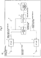
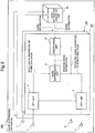
- Fig. 1 is a block diagram showing the overall arrangement of a noise suppressing apparatus 100.
- the noise suppressing apparatus 100 functions as part of a device such as a digital camera, a notebook computer, or a mobile phone.
- the exemplary embodiment is not limited to this and is also applicable to an information processing apparatus of any type that requires noise removal from an input signal.
- Fig. 12 is a block diagram showing an example of the arrangement of an information processing apparatus 1200 according to the exemplary embodiment.
- the information processing apparatus 1200 includes a noise suppression unit 3 and a modification unit 7.
- a noisy signal is input to an input terminal 1 as a sample value sequence.
- An FFT unit 2 performs transform such as Fourier transform of the noisy signal supplied to the input terminal 1, thereby dividing the signal into a plurality of frequency components.
- the noise suppression unit 3 receives the magnitude spectrum out of the plurality of frequency components, whereas an IFFT unit 4 is provided with the phase spectrum. Note that the magnitude spectrum is supplied to the noise suppression unit 3 in this case.
- the exemplary embodiment is not limited to this, and a power spectrum corresponding to the square of the magnitude spectrum may be supplied to the noise suppression unit 3.
- a noise information memory 6 includes a memory element such as a semiconductor memory and stores noise information (information about noise characteristics).
- the noise information memory 6 stores noise spectrum forms as the noise information.
- the noise information memory 6 can also store, for example, the frequency characteristics of phases and features such as the intensities and time-rate changes for a specific frequency in place of or together with the spectra.
- the noise information can also include statistics (maxima, minima, variances, and medians) and the like.
- the noise information recorded in the noise information memory 6 is supplied to the modification unit 7.
- the modification unit 7 modifies the noise information into modified noise information by multiplying a scaling factor and supplies the modified noise information to the noise suppression unit 3.
- the noise suppression unit 3 suppresses noise at each frequency using the noisy signal magnitude spectrum supplied by the FFT unit 2 and the modified noise information supplied by the modification unit 7, and provides the IFFT unit 4 with an enhanced signal magnitude spectrum as a noise suppression result.
- the modification unit 7 is also simultaneously provided with the enhanced signal magnitude spectrum. The modification unit 7 modifies the noise information based on the enhanced signal magnitude spectrum as the noise suppression result.
- the IFFT unit 4 inversely transforms the combination of the enhanced signal magnitude spectrum supplied from the noise suppression unit 3 and the noisy signal phase supplied from the FFT unit 2, and supplies an enhanced signal sample to an output terminal 5.
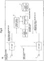
- Fig. 2 is a block diagram showing the arrangement of the FFT unit 2.
- the FFT unit 2 includes a frame dividing unit 21, a windowing unit 22, and a Fourier transform unit 23.
- the frame dividing unit 21 receives the noisy signal sample and divides it into frames corresponding to K/2 samples, where K is an even number.
- the noisy signal sample divided into frames is supplied to the windowing unit 22 and multiplied by a window function w(t).
- a symmetric window function is used for a real signal.
- the windowing unit 22 may use various window functions such as a hamming window, a Kaiser window, and a Blackman window.
- the windowed output is supplied to the Fourier transform unit 23 and transformed into a noisy signal spectrum Yn(k).
- the noisy signal spectrum Yn(k) is separated into the phase and the magnitude.
- a noisy signal phase spectrum argYn(k) is supplied to the IFFT unit 4, whereas a noisy signal magnitude spectrum
- the FFT unit 2 can use the power spectrum instead of the magnitude spectrum.
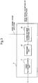
- Fig. 3 is a block diagram showing the arrangement of the IFFT unit 4.
- the IFFT unit 4 includes an inverse Fourier transform unit 43, a windowing unit 42, and a frame reconstruction unit 41.
- the inverse Fourier transform unit 43 inversely Fourier-transforms the resultant enhanced signal.
- the frame reconstruction unit 41 provides the output terminal 5 with the resultant output signal.
- the transform in the FFT unit 2 and the IFFT unit 4 in Figs. 2 and 3 has been described above as Fourier transform.
- the FFT unit 2 and the IFFT unit 4 can use any other transform such as cosine transform, modified discrete cosine transform (MDCT), Hadamard transform, Haar transform, or Wavelet transform in place of the Fourier transform.
- cosine transform or modified cosine transform obtains only a magnitude as a transform result. This obviates the necessity for the path from the FFT unit 2 to the IFFT unit 4 in Fig. 1 .
- the noise information recorded in the noise information memory 6 needs to include only magnitudes (or powers), contributing to reduction of the memory size and the number of computations of a noise suppressing process.
- Haar transform allows to omit multiplication and reduce the area of an LSI chip. Since Wavelet transform can change the time resolution depending on the frequency, better noise suppression is expected.
- the noise suppression unit 3 may perform actual suppression.
- the FFT unit 2 can achieve high sound quality by integrating more frequency components from the low frequency range where the discrimination capability of hearing characteristics is high to the high frequency range with a poorer capability.
- noise suppression is executed after integrating a plurality of frequency components, the number of frequency components to which noise suppression is applied decreases. The noise suppressing apparatus 100 can thus decrease the whole number of computations.
- the noise suppression unit 3 can perform various kinds of suppression. Typical suppressing methods are the SS (Spectrum Subtraction) method and the MMSE STSA (Minimum Mean-Square Error Short-Time Spectral Amplitude Estimator) method.
- the noise suppression unit 3 subtracts the modified noise information supplied by the modification unit 7 from the noisy signal magnitude spectrum supplied by the FFT unit 2.
- the noise suppression unit 3 calculates a spectral gain for each of the plurality of frequency components using the modified noise information supplied by the modification unit 7 and the noisy signal magnitude spectrum supplied by the FFT unit 2. The noise suppression unit 3 then multiplies the noisy signal magnitude spectrum by the spectral gain. The spectral gain is determined so as to minimize the mean square power of the enhanced signal.
- the noise suppression unit 3 can apply flooring to avoid excessive noise suppression.
- Flooring is a method of avoiding suppression beyond the maximum suppression amount.
- a flooring parameter determines the maximum suppression amount.
- the noise suppression unit 3 imposes restrictions so the result obtained by subtracting the modified noise information from the noisy signal magnitude spectrum is not smaller than the flooring parameter. More specifically, if the subtraction result is smaller than the flooring parameter, the noise suppression unit 3 replaces the subtraction result with the flooring parameter.
- the noise suppression unit 3 replaces the spectral gain with the flooring parameter. Details of the flooring are disclosed in literature " M. Berouti, R. Schwartz, and J.
- the noise suppression unit 3 can also set the number of frequency components of the noise information to be smaller than the number of frequency components of the noisy signal spectrum. At this time, a plurality of frequency components share a plurality of pieces of noise information.
- the frequency resolution of the noisy signal spectrum is higher than in a case in which the plurality of frequency components are integrated for both the noisy signal spectrum and the noise information. For this reason, the noise suppression unit 3 can achieve high sound quality by calculation in an amount smaller than in case of the absence of frequency component integration.
- Japanese Patent Laid-Open No. 2008-203879 discloses details of suppression using noise information whose number of frequency components is smaller than the number of frequency components of the noisy signal spectrum.
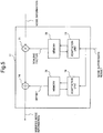
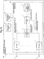
- Fig. 4 is a block diagram showing the arrangement of the modification unit 7.
- the modification unit 7 includes a multiplier 71, a memory 72, and an adaptation unit 73.
- the noise information supplied to the modification unit 7 is supplied to the multiplier 71.
- the memory 72 stores a scaling factor serving as modification information to be used to modify the noise information.
- the multiplier 71 obtains the product of the noise information and a scaling factor and outputs the product as modified noise information.
- the noise suppression unit 3 supplies the enhanced signal magnitude spectrum as the noise suppression result to the adaptation unit 73.
- the adaptation unit 73 reads out the scaling factor from the memory 72, changes the scaling factor using the noise suppression result, and supplies the new scaling factor after the change to the memory 72.
- the memory 72 newly stores the new scaling factor in place of the old scaling factor stored so far.
- the adaptation unit 73 adapts the scaling factor such that the larger the noise suppression result at a timing without target signal input is (the larger the noise remaining without being suppressed is), the larger the modified noise information is.
- the large noise suppression result at the timing without target signal input indicates insufficient suppression.
- the modified noise information is preferably made larger by changing the scaling factor.
- the modified noise information is large, the subtraction value of the SS method is large, and the noise suppression result thus becomes small.
- the signal-to-noise ratio (SNR) estimate to be used to calculate the spectral gain is small, and therefore, a small spectral gain can be obtained. This leads to more intensive suppression.
- a plurality of methods are available to adapt the scaling factor. A re-calculation algorithm and a recursive adaptation algorithm will be described as examples.
- the modification unit 7 can recalculate or recursively adapt the scaling factor, for example, when the magnitude or power of the noisy signal is small so as to completely suppress noise. This is because the power of the signal other than the noise to be suppressed is small at high probability when the magnitude or power of the noisy signal is small.
- the modification unit 7 can detect the small magnitude or power of the noisy signal using the fact that the magnitude or power of the noisy signal is smaller than a threshold.
- the modification unit 7 can also detect the small magnitude or power of the noisy signal using the fact that the difference between the magnitude or power of the noisy signal and the noise information recorded in the noise information memory 6 is smaller than a threshold. That is, the modification unit 7 uses the fact that when the magnitude or power of the noisy signal is similar to the noise information, the noise information makes up a large part of the noisy signal (the SNR is low). Especially, the modification unit 7 can compare the spectral envelopes using a combination of information at a plurality of frequency points, thereby raising the detection accuracy.
- the scaling factor in the SS method is recalculated such that the modified noise information equals the noisy signal spectrum for each frequency at the timing without target signal input.
- the adaptation unit 73 obtains a scaling factor ⁇ n(k) so as to make the noisy signal magnitude spectrum
- supplied from the FFT unit 2 when only noise has been input match the product of the scaling factor ⁇ n and noise information v(k). That is, the scaling factor an(k) is calculated by ⁇ n k Yn k / ⁇ n k where n is the frame number, and k is the frequency number.
- recursive adaptation of the scaling factor in the SS method is done by gradually adapting the scaling factor such that the enhanced signal magnitude spectrum at the timing without target signal input approaches zero for each frequency.
- the modification unit 7 can implement accurate noise suppression in real time by immediately adapting the scaling factor.
- the modification unit 7 may use the LS (Least Squares) algorithm or any other adaptive algorithm.
- the modification unit 7 can also immediately apply the adapted scaling factor.
- the implementor of the noise suppressing apparatus 100 may design the modification unit 7 to adapt the scaling factor in real time by modifying equations (11) to (13) with reference to the change from equation (9) to equation (10).
- the MMSE STSA method recursively adapts the scaling factor.
- the modification unit 7 adapts the scaling factor ⁇ n(k) for each frequency by the same methods as those described using equations (8) to (13).
- the modification unit 7 may change the adaptation method so as to, for example, first use the re-calculation algorithm and then use the recursive adaptation algorithm.
- the modification unit 7 may change the adaptation method on condition that the scaling factor has sufficiently approached the optimum value.
- the modification unit 7 may change the adaptation method when, for example, a predetermined time has elapsed. Otherwise, the modification unit 7 may change the adaptation method when the modification amount of the scaling factor has fallen below a predetermined threshold.
- the noise suppressing apparatus 100 of the exemplary embodiment adapts, based on the noise suppression result, modification information to be used for the modification. It is therefore possible to suppress various kinds of noise including unknown noise without storing a number of pieces of noise information in advance.
- the scaling factor is used as the modification information to be used to modify the noise signal.
- the exemplary embodiment is not limited to this.
- a value obtained by adding an offset to the scaling factor may be used as the modification information. In this case, both the scaling factor and the offset are adapted based on the noise suppression result.
- Fig. 5 is a block diagram showing the arrangement of a modification unit 17 according to the exemplary embodiment.
- the modification unit 17 includes an adder 74, a memory 75, and an adaptation unit 76 in addition to the arrangement described with reference to Fig. 4 .
- the operations of a multiplier 71, a memory 72, and an adaptation unit 73 are the same as those described using Fig. 4 , and a description thereof will not be repeated.
- the multiplier 71 multiplies input noise information by the scaling factor read out from the memory 72 and supplies the product to the adder 74.
- the adder 74 subtracts an offset value stored in the memory 75 from the output of the multiplier 71 and outputs the difference as modified noise information.
- the adaptation unit 76 receives, from a noise suppression unit 3, the same noise suppression result as that for the adaptation unit 73, adapts the offset value stored in the memory 75 using the noise suppression result, and supplies the new offset value to the memory 75.
- the memory 75 newly stores the new offset value in place of the old offset value stored so far.
- a noise suppressing apparatus 100 of the exemplary embodiment uses the scaling factor and the offset as the modification information to be used to modify noise information. This allows to more finely modify the noise information and consequently improve the noise suppression effect.
- the scaling factor and the offset have been exemplified as the modification information.
- the exemplary embodiments are not limited to this, and any other information (for example, a polynomial or nonlinear function of noise information) may be used.
- a noise suppressing apparatus 300 according to the third exemplary embodiment includes no noise information memory 6, unlike the above-described first exemplary embodiment.
- a modification unit 67 is provided with a real-time noise spectrum input from an input terminal 61. The remaining arrangements and operations are the same as in the first exemplary embodiment, and a detailed description thereof will not be repeated.
- the modification unit 67 generates modified noise information by modifying the noise information based on the noise suppression result, and provides a noise suppression unit 3 with the modified noise information, as in the first exemplary embodiment.
- the noise suppressing apparatus 300 of the exemplary embodiment can obtain more accurate noise information and also follow variations in noise. It is therefore possible to more effectively suppress various kinds of noise including unknown noise without storing a number of pieces of noise information in advance.
- the presence of the modification unit 67 enables to follow variations in the electrical characteristics of the target signal microphone and the noise microphone.
- a noise suppression unit 3 and a modification unit 77 included in a noise suppressing apparatus 400 according to the fourth exemplary embodiment additionally receive, from an input terminal 9, information (noise existence information) representing whether specific noise exists in the input noisy signal. This makes it possible to reliably suppress noise at a timing specific noise exists and simultaneously adapt the modification information.
- information noise existence information
- the noise suppressing apparatus 400 of the exemplary embodiment does not adapt the modification information at a timing specific noise does not exist. Hence, a higher noise suppression accuracy can be obtained for the specific noise.
- a noise suppressing apparatus 500 of the exemplary embodiment includes a target signal detecting unit 81.
- An FFT unit 2 provides the target signal detecting unit 81 with a noisy signal magnitude spectrum.
- the target signal detecting unit 81 analyzes the noisy signal magnitude spectrum and determines whether the target signal exists or the degree of existence.
- a modification unit 87 Based on the determination result from the target signal detecting unit 81, a modification unit 87 adapts modification information to be used to modify noise information. For example, without the target signal, the noisy signal includes only noise, and the suppression result of a noise suppression unit 3 has to be zero. Hence, the modification unit 87 adjusts the scaling factor and the like so as to obtain zero as the noise suppression result at this time.
- the modification unit 87 adapts the modification information in accordance with the existence ratio of the target signal. For example, if the ratio of the target signal existing in the noisy signal is 10%, the modification unit 87 adapts the modification information partially (only 90%).
- the noise suppressing apparatus 500 of the exemplary embodiment adapts the modification information in accordance with the ratio of noise in the noisy signal. This allows to obtain a more accurate noise suppression result.
- a noise suppressing apparatus 600 includes no noise information memory 6 but a noise information generation unit 63 instead.
- the noise information generation unit 63 generates noise information using signals input from a plurality of input terminals 1 and 11 and provides a modification unit 97 with the noise information.
- the noise suppressing apparatus 600 can form directivity.
- the noise suppressing apparatus 600 can form a sharp direction of a low sensitivity (null).
- the noise suppressing apparatus 600 makes the direction of a low sensitivity match the direction of arrival (DOA) of the target signal to suppress only the target signal, thereby extracting only noise as the output.
- DOA direction of arrival
- Fig. 10 is a block diagram showing an information processing apparatus 700 including a noise suppressing apparatus 100 described in the first exemplary embodiment.
- the information processing apparatus 700 includes a mechanical unit 91 serving as a noise source, and a mechanical control unit 92 that controls the mechanical unit 91.
- the noise suppressing apparatus 100 is provided with the operation information. This allows the noise suppressing apparatus 100 to reliably operate to adapt modification information during the operation of the mechanical unit 91.
- the mechanical control unit 92 may operate the mechanical unit 91 based on an instruction from the noise suppressing apparatus 100 to generate noise, and simultaneously, a modification unit 7 in the noise suppressing apparatus 100 may adapt modification information using a noisy signal including the noise.
- the first to seventh exemplary embodiments have been described above concerning noise suppressing apparatuses having different characteristic features.
- Exemplary embodiments also incorporate noise suppressing apparatuses formed by combining the characteristic features in whatever way.
- the present invention may be applied to a system including a plurality of devices or a single apparatus.
- the present invention is also applicable when the signal processing program of software for implementing the functions of the exemplary embodiments to the system or apparatus directly or from a remote site.
- the present invention also incorporates a program that is installed in a computer to cause the computer to implement the functions of the present invention, a medium that stores the program, and a WWW server from which the program is downloaded.
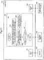
- Fig. 11 is a block diagram of a computer 1000 that executes a signal processing program configured as the first to seventh exemplary embodiments.
- the computer 1000 includes an input unit 1001, a CPU 1002, an output unit 1003, a memory 1004, an external memory 1005, and a communication control unit 1006.
- the CPU 1002 controls the operation of the computer 1000 by reading out the signal processing program. More specifically, upon executing the signal processing program, the CPU 1002 modifies, based on modification information, a noise signal associated with noise in the noisy signal, thereby calculating modified noise information (S801). Next, the CPU 1002 suppresses the noise in the noisy signal using the modified noise information (S802). The CPU 1002 determines whether a deactivate event has been input (S804). If no deactivate event has been input, the CPU 1002 adapts the modification information using the noise suppression result (S803). If a deactivate event has been input, the CPU 1002 ends the signal processing. That is, the CPU 1002 repeatedly executes noise information generation/adaptation and noise suppression until the deactivate event is input. Various deactivate events are assumed, including power-off and microphone-off.
Landscapes
- Engineering & Computer Science (AREA)
- Computational Linguistics (AREA)
- Quality & Reliability (AREA)
- Signal Processing (AREA)
- Health & Medical Sciences (AREA)
- Audiology, Speech & Language Pathology (AREA)
- Human Computer Interaction (AREA)
- Physics & Mathematics (AREA)
- Acoustics & Sound (AREA)
- Multimedia (AREA)
- Noise Elimination (AREA)
- Soundproofing, Sound Blocking, And Sound Damping (AREA)
- Circuit For Audible Band Transducer (AREA)
Description
- This application is based upon and claims the benefit of priority from Japanese patent application No.
2009-255420, filed on November 6, 2009 - The present invention relates to a signal processing technique of suppressing noise in a noisy signal to enhance a target signal.
- A noise suppressing technology is known as a signal processing technology of partially or completely suppressing noise in a noisy signal (a signal containing a mixture of noise and a target signal) and outputting an enhanced signal (a signal obtained by enhancing the target signal). For example, a noise suppressor is a system that suppresses noise mixed in a target audio signal. The noise suppressor is used in various audio terminals such as mobile phones.
- Concerning technologies of this type,
patent literature 1 discloses a method of suppressing noise by multiplying an input signal by a spectral gain smaller than 1.Patent literature 2 discloses a method of suppressing noise by directly subtracting estimated noise from a noisy signal. - The techniques described in
patent literatures patent literatures patent literatures - On the other hand,
patent literature 3 discloses a noise suppressing system capable of implementing a sufficient noise suppression effect and a smaller distortion in the enhanced signal even if the condition that the noise is much smaller than the target signal is not satisfied. Assuming that the characteristics of noise to be mixed into the target signal are known in advance to a certain extent, the method described inpatent literature 3 subtracts previously recorded noise information (information about the noise characteristics) from the noisy signal, thereby suppressing the noise.Patent literature 3 also discloses a method of, if an input signal power obtained by analyzing an input signal is large, integrating a large coefficient into noise information, or if the input signal power is small, integrating a small coefficient, and subtracting the integration result from the noisy signal. -
- [PTL 1] Japanese Patent No.
4282227 - [PTL 2] Japanese Patent Laid-Open No.
8-221092 - [PTL 3] Japanese Patent Laid-Open No.
2006-279185 - However, the arrangement disclosed in
patent literature 3 described above needs to store noise characteristic information in advance, and the types of erasable noise are extremely limited. To increase the types of erasable noise, a number of pieces of noise information need to be recorded. This increases the necessary memory size and the manufacturing cost of the apparatus. In addition, the technique disclosed inpatent literature 3 cannot suppress unknown noise different from the stored noise information. - The present invention has been made in consideration of the above-described situation, and has as its exemplary object to provide a signal processing technique of solving the above-described problems.
- In order to achieve the above exemplary object, a method according to
claim 1 is proposed. - In order to achieve the above exemplary object, an apparatus according to
claim 7 and a program stored in a program recording medium according toclaim 9 are likewise proposed. - According to the present invention, it is possible to provide a signal processing technique of suppressing various kinds of noise including unknown noise without storing a number of pieces of noise information in advance.
-
-
Fig. 1 is a block diagram showing the schematic arrangement of anoise suppressing apparatus 100 according to a first exemplary embodiment, in accordance with the the present invention; -
Fig. 2 is a block diagram showing the arrangement of an FFT (Fast Fourier Transform)unit 2 included in thenoise suppressing apparatus 100 according to the first exemplary embodiment; -
Fig. 3 is a block diagram showing the arrangement of an IFFT (Inverse Fast Fourier Transform)unit 4 included in thenoise suppressing apparatus 100 according to the first exemplary embodiment; -
Fig. 4 is a block diagram showing the arrangement of a modification unit included in thenoise suppressing apparatus 100 according to the first exemplary embodiment; -
Fig. 5 is a block diagram showing another arrangement of a modification unit included in anoise suppressing apparatus 100 according to a second exemplary embodiment in accordance with the present invention; -
Fig. 6 is a block diagram showing the schematic arrangement of anoise suppressing apparatus 300 according to a third exemplary embodiment ; -
Fig. 7 is a block diagram showing the schematic arrangement of anoise suppressing apparatus 400 according to a fourth exemplary embodiment, in accordance with the present invention; -
Fig. 8 is a block diagram showing the schematic arrangement of anoise suppressing apparatus 500 according to a fifth exemplary embodiment, in accordance with the present invention; -
Fig. 9 is a block diagram showing the schematic arrangement of anoise suppressing apparatus 600 according to a sixth exemplary embodiment ; -
Fig. 10 is a block diagram showing the schematic arrangement of aninformation processing apparatus 700 including anoise suppressing apparatus 100 according to a seventh exemplary embodiment, in accordance with the present invention; -
Fig. 11 is a schematic block diagram of acomputer 1000 that executes a signal processing program according to still another exemplary embodiment, in accordance with the present invention; and -
Fig. 12 is a block diagram showing an example of the arrangement of aninformation processing apparatus 1200 according to the present invention. - Exemplary embodiments will now be described in detail by way of example with reference to the accompanying drawings. Note that the constituent elements described in the exemplary embodiments are merely examples, and the technical scope is not limited by the following exemplary embodiments.
- As the first exemplary embodiment for implementing a signal processing method, a noise suppressing apparatus will be explained, which partially or completely suppresses noise in a noisy signal (a signal containing a mixture of noise and a target signal) and outputs an enhanced signal (a signal obtained by enhancing the target signal).
Fig. 1 is a block diagram showing the overall arrangement of anoise suppressing apparatus 100. Thenoise suppressing apparatus 100 functions as part of a device such as a digital camera, a notebook computer, or a mobile phone. However, the exemplary embodiment is not limited to this and is also applicable to an information processing apparatus of any type that requires noise removal from an input signal.Fig. 12 is a block diagram showing an example of the arrangement of aninformation processing apparatus 1200 according to the exemplary embodiment. Theinformation processing apparatus 1200 includes anoise suppression unit 3 and amodification unit 7. - A noisy signal is input to an
input terminal 1 as a sample value sequence. AnFFT unit 2 performs transform such as Fourier transform of the noisy signal supplied to theinput terminal 1, thereby dividing the signal into a plurality of frequency components. Thenoise suppression unit 3 receives the magnitude spectrum out of the plurality of frequency components, whereas anIFFT unit 4 is provided with the phase spectrum. Note that the magnitude spectrum is supplied to thenoise suppression unit 3 in this case. However, the exemplary embodiment is not limited to this, and a power spectrum corresponding to the square of the magnitude spectrum may be supplied to thenoise suppression unit 3. - A
noise information memory 6 includes a memory element such as a semiconductor memory and stores noise information (information about noise characteristics). In particular, thenoise information memory 6 stores noise spectrum forms as the noise information. However, thenoise information memory 6 can also store, for example, the frequency characteristics of phases and features such as the intensities and time-rate changes for a specific frequency in place of or together with the spectra. The noise information can also include statistics (maxima, minima, variances, and medians) and the like. The noise information recorded in thenoise information memory 6 is supplied to themodification unit 7. Themodification unit 7 modifies the noise information into modified noise information by multiplying a scaling factor and supplies the modified noise information to thenoise suppression unit 3. - The
noise suppression unit 3 suppresses noise at each frequency using the noisy signal magnitude spectrum supplied by theFFT unit 2 and the modified noise information supplied by themodification unit 7, and provides theIFFT unit 4 with an enhanced signal magnitude spectrum as a noise suppression result. Themodification unit 7 is also simultaneously provided with the enhanced signal magnitude spectrum. Themodification unit 7 modifies the noise information based on the enhanced signal magnitude spectrum as the noise suppression result. - The
IFFT unit 4 inversely transforms the combination of the enhanced signal magnitude spectrum supplied from thenoise suppression unit 3 and the noisy signal phase supplied from theFFT unit 2, and supplies an enhanced signal sample to anoutput terminal 5. -
Fig. 2 is a block diagram showing the arrangement of theFFT unit 2. As shown inFig. 2 , theFFT unit 2 includes aframe dividing unit 21, awindowing unit 22, and aFourier transform unit 23. Theframe dividing unit 21 receives the noisy signal sample and divides it into frames corresponding to K/2 samples, where K is an even number. The noisy signal sample divided into frames is supplied to thewindowing unit 22 and multiplied by a window function w(t). The signal obtained by windowing an nth frame input signal yn(t) (t = 0, 1,..., K/2-1) by w(t) is given by
- Also widely conducted is windowing two successive frames partially overlaid (overlapping) each other. Assume that the overlap length is 50% the frame length. For t = 0, 1,..., K/2-1, the
windowing unit 22 outputsy n(t) andy n(t + K / 2) given by
- A symmetric window function is used for a real signal. The window function makes the input signal match the output signal except an error when the spectral gain is set to 1 in the MMSE STSA method or zero is subtracted in the SS method. This means w(t) = w(t + K/2) = 1.
- The example of windowing two successive frames that overlap 50% will continuously be described below. The
windowing unit 22 can use, for example, a hanning window w(t) given by
- Alternatively, the
windowing unit 22 may use various window functions such as a hamming window, a Kaiser window, and a Blackman window. The windowed output is supplied to theFourier transform unit 23 and transformed into a noisy signal spectrum Yn(k). The noisy signal spectrum Yn(k) is separated into the phase and the magnitude. A noisy signal phase spectrum argYn(k) is supplied to theIFFT unit 4, whereas a noisy signal magnitude spectrum |Yn(k)| is supplied to thenoise suppression unit 3. As already described, theFFT unit 2 can use the power spectrum instead of the magnitude spectrum. -
Fig. 3 is a block diagram showing the arrangement of theIFFT unit 4. As shown inFig. 3 , theIFFT unit 4 includes an inverseFourier transform unit 43, awindowing unit 42, and aframe reconstruction unit 41. The inverseFourier transform unit 43 combines the enhanced signal magnitude spectrum supplied from thenoise suppression unit 3 with the noisy signal phase spectrum argYn(k) supplied from theFFT unit 2 to obtain an enhanced signal given by
- The inverse
Fourier transform unit 43 inversely Fourier-transforms the resultant enhanced signal. The inversely Fourier-transformed enhanced signal is supplied to thewindowing unit 42 as a series of time domain samples xn(t) (t = 0, 1,..., K-1) in which one frame includes K samples and multiplied by the window function w(t). The signal obtained by windowing an nth frame input signal xn(t) (t = 0, 1,..., K/2-1) by w(t) is given by
- Also widely conducted is windowing two successive frames partially overlaid (overlapping) each other. Assume that the overlap length is 50% the frame length. For t = 0, 1,..., K/2-1, the
windowing unit 42 outputsx n(t) andx n(t + K / 2) given by
frame reconstruction unit 41 with them. - The
frame reconstruction unit 41 extracts the output of two adjacent frames from thewindowing unit 42 for every K/2 samples, overlays them, and obtains an output signal x̂n(t) given by
frame reconstruction unit 41 provides theoutput terminal 5 with the resultant output signal. - Note that the transform in the
FFT unit 2 and theIFFT unit 4 inFigs. 2 and3 has been described above as Fourier transform. However, theFFT unit 2 and theIFFT unit 4 can use any other transform such as cosine transform, modified discrete cosine transform (MDCT), Hadamard transform, Haar transform, or Wavelet transform in place of the Fourier transform. For example, cosine transform or modified cosine transform obtains only a magnitude as a transform result. This obviates the necessity for the path from theFFT unit 2 to theIFFT unit 4 inFig. 1 . In addition, the noise information recorded in thenoise information memory 6 needs to include only magnitudes (or powers), contributing to reduction of the memory size and the number of computations of a noise suppressing process. Haar transform allows to omit multiplication and reduce the area of an LSI chip. Since Wavelet transform can change the time resolution depending on the frequency, better noise suppression is expected. - Alternatively, after the
FFT unit 2 has integrated a plurality of frequency components, thenoise suppression unit 3 may perform actual suppression. In this case, theFFT unit 2 can achieve high sound quality by integrating more frequency components from the low frequency range where the discrimination capability of hearing characteristics is high to the high frequency range with a poorer capability. When noise suppression is executed after integrating a plurality of frequency components, the number of frequency components to which noise suppression is applied decreases. Thenoise suppressing apparatus 100 can thus decrease the whole number of computations. - The
noise suppression unit 3 can perform various kinds of suppression. Typical suppressing methods are the SS (Spectrum Subtraction) method and the MMSE STSA (Minimum Mean-Square Error Short-Time Spectral Amplitude Estimator) method. When using the SS method, thenoise suppression unit 3 subtracts the modified noise information supplied by themodification unit 7 from the noisy signal magnitude spectrum supplied by theFFT unit 2. When using the MMSE STSA method, thenoise suppression unit 3 calculates a spectral gain for each of the plurality of frequency components using the modified noise information supplied by themodification unit 7 and the noisy signal magnitude spectrum supplied by theFFT unit 2. Thenoise suppression unit 3 then multiplies the noisy signal magnitude spectrum by the spectral gain. The spectral gain is determined so as to minimize the mean square power of the enhanced signal. - The
noise suppression unit 3 can apply flooring to avoid excessive noise suppression. Flooring is a method of avoiding suppression beyond the maximum suppression amount. A flooring parameter determines the maximum suppression amount. When using the SS method, thenoise suppression unit 3 imposes restrictions so the result obtained by subtracting the modified noise information from the noisy signal magnitude spectrum is not smaller than the flooring parameter. More specifically, if the subtraction result is smaller than the flooring parameter, thenoise suppression unit 3 replaces the subtraction result with the flooring parameter. In case of using the MMSE STSA method, if the spectral gain obtained from the modified noise information and the noisy signal magnitude spectrum is smaller than the flooring parameter, thenoise suppression unit 3 replaces the spectral gain with the flooring parameter. Details of the flooring are disclosed in literature "M. Berouti, R. Schwartz, and J. Makhoul, "Enhancement of speech corrupted by acoustic noise", Proceedings of ICASSP'79, pp. 208-211, Apr. 1979". When the flooring is introduced, thenoise suppression unit 3 does not perform excessive suppression. The flooring can prevent the enhanced signal from having a larger distortion. - The
noise suppression unit 3 can also set the number of frequency components of the noise information to be smaller than the number of frequency components of the noisy signal spectrum. At this time, a plurality of frequency components share a plurality of pieces of noise information. The frequency resolution of the noisy signal spectrum is higher than in a case in which the plurality of frequency components are integrated for both the noisy signal spectrum and the noise information. For this reason, thenoise suppression unit 3 can achieve high sound quality by calculation in an amount smaller than in case of the absence of frequency component integration. Japanese Patent Laid-Open No.2008-203879 -
Fig. 4 is a block diagram showing the arrangement of themodification unit 7. As shown inFig. 4 , themodification unit 7 includes amultiplier 71, amemory 72, and anadaptation unit 73. The noise information supplied to themodification unit 7 is supplied to themultiplier 71. Thememory 72 stores a scaling factor serving as modification information to be used to modify the noise information. Themultiplier 71 obtains the product of the noise information and a scaling factor and outputs the product as modified noise information. - On the other hand, the
noise suppression unit 3 supplies the enhanced signal magnitude spectrum as the noise suppression result to theadaptation unit 73. Theadaptation unit 73 reads out the scaling factor from thememory 72, changes the scaling factor using the noise suppression result, and supplies the new scaling factor after the change to thememory 72. Thememory 72 newly stores the new scaling factor in place of the old scaling factor stored so far. - When adapting the scaling factor using the noise suppression result fed back to the
modification unit 7, theadaptation unit 73 adapts the scaling factor such that the larger the noise suppression result at a timing without target signal input is (the larger the noise remaining without being suppressed is), the larger the modified noise information is. The large noise suppression result at the timing without target signal input indicates insufficient suppression. For this reason, the modified noise information is preferably made larger by changing the scaling factor. When the modified noise information is large, the subtraction value of the SS method is large, and the noise suppression result thus becomes small. In multiplication-based suppression such as the MMSE STSA method, the signal-to-noise ratio (SNR) estimate to be used to calculate the spectral gain is small, and therefore, a small spectral gain can be obtained. This leads to more intensive suppression. A plurality of methods are available to adapt the scaling factor. A re-calculation algorithm and a recursive adaptation algorithm will be described as examples. - In an ideal noise suppression result, noise is completely suppressed. The
modification unit 7 can recalculate or recursively adapt the scaling factor, for example, when the magnitude or power of the noisy signal is small so as to completely suppress noise. This is because the power of the signal other than the noise to be suppressed is small at high probability when the magnitude or power of the noisy signal is small. Themodification unit 7 can detect the small magnitude or power of the noisy signal using the fact that the magnitude or power of the noisy signal is smaller than a threshold. - The
modification unit 7 can also detect the small magnitude or power of the noisy signal using the fact that the difference between the magnitude or power of the noisy signal and the noise information recorded in thenoise information memory 6 is smaller than a threshold. That is, themodification unit 7 uses the fact that when the magnitude or power of the noisy signal is similar to the noise information, the noise information makes up a large part of the noisy signal (the SNR is low). Especially, themodification unit 7 can compare the spectral envelopes using a combination of information at a plurality of frequency points, thereby raising the detection accuracy. - The scaling factor in the SS method is recalculated such that the modified noise information equals the noisy signal spectrum for each frequency at the timing without target signal input. In other words, the
adaptation unit 73 obtains a scaling factor αn(k) so as to make the noisy signal magnitude spectrum |Yn(k)| supplied from theFFT unit 2 when only noise has been input match the product of the scaling factor αn and noise information v(k). That is, the scaling factor an(k) is calculated by
- On the other hand, recursive adaptation of the scaling factor in the SS method is done by gradually adapting the scaling factor such that the enhanced signal magnitude spectrum at the timing without target signal input approaches zero for each frequency. When using the LMS (Least Squares Method) algorithm for recursive adaptation, the
modification unit 7 calculates αn+1(k) using an error en(k) of the nth frame for the frequency number k as
modification unit 7 uses
modification unit 7 calculates the current scaling factor αn(k) using the current error and immediately applies it. Themodification unit 7 can implement accurate noise suppression in real time by immediately adapting the scaling factor. - When using the NLMS (Normalized Least Squares Method) algorithm, the
modification unit 7 calculates the scaling factor αn+1(k) using the above-described error en(k) as
- The
modification unit 7 may calculate the scaling factor αn+1(k) using a perturbation method as
- Alternatively, the
modification unit 7 may calculate the scaling factor αn+1(k) using a signum function sgn{en(k)} representing only the sign of the error as
- Similarly, the
modification unit 7 may use the LS (Least Squares) algorithm or any other adaptive algorithm. Themodification unit 7 can also immediately apply the adapted scaling factor. In this case, the implementor of thenoise suppressing apparatus 100 may design themodification unit 7 to adapt the scaling factor in real time by modifying equations (11) to (13) with reference to the change from equation (9) to equation (10). - The MMSE STSA method recursively adapts the scaling factor. The
modification unit 7 adapts the scaling factor αn(k) for each frequency by the same methods as those described using equations (8) to (13). - As the characteristic features of the above-described re-calculation and recursive adaptation algorithms serving as the scaling factor adaptation method, the re-calculation algorithm has a high follow-up speed, and the recursive adaptation algorithm has a high accuracy. To make use these characteristic features, the
modification unit 7 may change the adaptation method so as to, for example, first use the re-calculation algorithm and then use the recursive adaptation algorithm. When determining the timing to change the adaptation method, themodification unit 7 may change the adaptation method on condition that the scaling factor has sufficiently approached the optimum value. Alternatively, themodification unit 7 may change the adaptation method when, for example, a predetermined time has elapsed. Otherwise, themodification unit 7 may change the adaptation method when the modification amount of the scaling factor has fallen below a predetermined threshold. - As described above, when modifying noise information to be used in noise suppression, the
noise suppressing apparatus 100 of the exemplary embodiment adapts, based on the noise suppression result, modification information to be used for the modification. It is therefore possible to suppress various kinds of noise including unknown noise without storing a number of pieces of noise information in advance. - The second exemplary embodiment will be described with reference to
Fig. 5 . In the first exemplary embodiment, the scaling factor is used as the modification information to be used to modify the noise signal. However, the exemplary embodiment is not limited to this. A value obtained by adding an offset to the scaling factor may be used as the modification information. In this case, both the scaling factor and the offset are adapted based on the noise suppression result. -
Fig. 5 is a block diagram showing the arrangement of amodification unit 17 according to the exemplary embodiment. As shown inFig. 5 , themodification unit 17 includes anadder 74, amemory 75, and anadaptation unit 76 in addition to the arrangement described with reference toFig. 4 . The operations of amultiplier 71, amemory 72, and anadaptation unit 73 are the same as those described usingFig. 4 , and a description thereof will not be repeated. - The
multiplier 71 multiplies input noise information by the scaling factor read out from thememory 72 and supplies the product to theadder 74. Theadder 74 subtracts an offset value stored in thememory 75 from the output of themultiplier 71 and outputs the difference as modified noise information. - On the other hand, the
adaptation unit 76 receives, from anoise suppression unit 3, the same noise suppression result as that for theadaptation unit 73, adapts the offset value stored in thememory 75 using the noise suppression result, and supplies the new offset value to thememory 75. Thememory 75 newly stores the new offset value in place of the old offset value stored so far. - As described above, a
noise suppressing apparatus 100 of the exemplary embodiment uses the scaling factor and the offset as the modification information to be used to modify noise information. This allows to more finely modify the noise information and consequently improve the noise suppression effect. - Note that in the first and second exemplary embodiments, the scaling factor and the offset have been exemplified as the modification information. However, the exemplary embodiments are not limited to this, and any other information (for example, a polynomial or nonlinear function of noise information) may be used.
- The third exemplary embodiment will be described with reference to
Fig. 6 . Anoise suppressing apparatus 300 according to the third exemplary embodiment includes nonoise information memory 6, unlike the above-described first exemplary embodiment. Hence, amodification unit 67 is provided with a real-time noise spectrum input from aninput terminal 61. The remaining arrangements and operations are the same as in the first exemplary embodiment, and a detailed description thereof will not be repeated. - For example, assume a case in which another microphone exists near the noise source, and the
input terminal 61 is provide with the output from the noise microphone. However, the exemplary embodiment is not limited to this and is also applicable to any other case if the noise information can be obtained externally. In this case as well, themodification unit 67 generates modified noise information by modifying the noise information based on the noise suppression result, and provides anoise suppression unit 3 with the modified noise information, as in the first exemplary embodiment. - The
noise suppressing apparatus 300 of the exemplary embodiment can obtain more accurate noise information and also follow variations in noise. It is therefore possible to more effectively suppress various kinds of noise including unknown noise without storing a number of pieces of noise information in advance. In particular, the presence of themodification unit 67 enables to follow variations in the electrical characteristics of the target signal microphone and the noise microphone. - The fourth exemplary embodiment will be described with reference to
Fig. 7 . Anoise suppression unit 3 and amodification unit 77 included in anoise suppressing apparatus 400 according to the fourth exemplary embodiment additionally receive, from aninput terminal 9, information (noise existence information) representing whether specific noise exists in the input noisy signal. This makes it possible to reliably suppress noise at a timing specific noise exists and simultaneously adapt the modification information. The remaining arrangements and operations are the same as in the first exemplary embodiment, and a detailed description thereof will not be repeated. - The
noise suppressing apparatus 400 of the exemplary embodiment does not adapt the modification information at a timing specific noise does not exist. Hence, a higher noise suppression accuracy can be obtained for the specific noise. - The fifth exemplary embodiment will be described with reference to
Fig. 8 . Anoise suppressing apparatus 500 of the exemplary embodiment includes a targetsignal detecting unit 81. AnFFT unit 2 provides the targetsignal detecting unit 81 with a noisy signal magnitude spectrum. The targetsignal detecting unit 81 analyzes the noisy signal magnitude spectrum and determines whether the target signal exists or the degree of existence. - Based on the determination result from the target
signal detecting unit 81, amodification unit 87 adapts modification information to be used to modify noise information. For example, without the target signal, the noisy signal includes only noise, and the suppression result of anoise suppression unit 3 has to be zero. Hence, themodification unit 87 adjusts the scaling factor and the like so as to obtain zero as the noise suppression result at this time. - On the other hand, when the noisy signal includes the target signal, the
modification unit 87 adapts the modification information in accordance with the existence ratio of the target signal. For example, if the ratio of the target signal existing in the noisy signal is 10%, themodification unit 87 adapts the modification information partially (only 90%). - The
noise suppressing apparatus 500 of the exemplary embodiment adapts the modification information in accordance with the ratio of noise in the noisy signal. This allows to obtain a more accurate noise suppression result. - The sixth exemplary embodiment will be described with reference to
Fig. 9 . Anoise suppressing apparatus 600 according to the exemplary embodiment includes nonoise information memory 6 but a noiseinformation generation unit 63 instead. The noiseinformation generation unit 63 generates noise information using signals input from a plurality ofinput terminals modification unit 97 with the noise information. With, for example, a plurality of microphones, thenoise suppressing apparatus 600 can form directivity. Especially for an acoustic signal, thenoise suppressing apparatus 600 can form a sharp direction of a low sensitivity (null). Thenoise suppressing apparatus 600 makes the direction of a low sensitivity match the direction of arrival (DOA) of the target signal to suppress only the target signal, thereby extracting only noise as the output. Details of directivity formation using a plurality of microphones are disclosed in, for example, literature "M. Brandstein and D. Ward, Eds., "Microphone Arrays", O. Hoshuyama and A. Sugiyama, Chap. 5, "Robust Adaptive Beamforming", Springer, Berlin, pp.87-109, Jan. 2001. According to this method, even when it is difficult to arrange a microphone near the noise source, noise information can be obtained in real time, in addition to the effect of the third exemplary embodiment. - The seventh exemplary embodiment will be described with reference to
Fig. 10. Fig. 10 is a block diagram showing aninformation processing apparatus 700 including anoise suppressing apparatus 100 described in the first exemplary embodiment. Theinformation processing apparatus 700 includes amechanical unit 91 serving as a noise source, and amechanical control unit 92 that controls themechanical unit 91. When themechanical control unit 92 operates themechanical unit 91 for some reason, thenoise suppressing apparatus 100 is provided with the operation information. This allows thenoise suppressing apparatus 100 to reliably operate to adapt modification information during the operation of themechanical unit 91. Alternatively, themechanical control unit 92 may operate themechanical unit 91 based on an instruction from thenoise suppressing apparatus 100 to generate noise, and simultaneously, amodification unit 7 in thenoise suppressing apparatus 100 may adapt modification information using a noisy signal including the noise. - The first to seventh exemplary embodiments have been described above concerning noise suppressing apparatuses having different characteristic features. Exemplary embodiments also incorporate noise suppressing apparatuses formed by combining the characteristic features in whatever way.
- The present invention may be applied to a system including a plurality of devices or a single apparatus. The present invention is also applicable when the signal processing program of software for implementing the functions of the exemplary embodiments to the system or apparatus directly or from a remote site. Hence, the present invention also incorporates a program that is installed in a computer to cause the computer to implement the functions of the present invention, a medium that stores the program, and a WWW server from which the program is downloaded.
-
Fig. 11 is a block diagram of acomputer 1000 that executes a signal processing program configured as the first to seventh exemplary embodiments. Thecomputer 1000 includes aninput unit 1001, aCPU 1002, anoutput unit 1003, amemory 1004, anexternal memory 1005, and acommunication control unit 1006. - The
CPU 1002 controls the operation of thecomputer 1000 by reading out the signal processing program. More specifically, upon executing the signal processing program, theCPU 1002 modifies, based on modification information, a noise signal associated with noise in the noisy signal, thereby calculating modified noise information (S801). Next, theCPU 1002 suppresses the noise in the noisy signal using the modified noise information (S802). TheCPU 1002 determines whether a deactivate event has been input (S804). If no deactivate event has been input, theCPU 1002 adapts the modification information using the noise suppression result (S803). If a deactivate event has been input, theCPU 1002 ends the signal processing. That is, theCPU 1002 repeatedly executes noise information generation/adaptation and noise suppression until the deactivate event is input. Various deactivate events are assumed, including power-off and microphone-off. - This makes it possible to obtain the same effects as in the first to seventh exemplary embodiments.
- While the present invention has been described above with reference to exemplary embodiments, the invention is not limited to the exemplary embodiments. The arrangement and details of the present invention can variously be modified without departing from the scope thereof which is defined by the appended claims, as will be understood by those skilled in the art.
Claims (9)
- A signal processing method for suppressing noise in a noisy audio signal comprising:(a) modifying noise information about characteristics of said noise, the noise information being stored in advance in a noise information memory (6), by multiplying said noise information by a scaling factor stored in a memory (72) to obtain modified noise information;(b) suppressing said noise in the noisy audio signal using said modified noise information; and(c) updating said scaling factor based on the result of said suppression.
- The signal processing method according to claim 1, wherein said modified noise information is modified by subtracting an offset from said noise information, and said offset is updated based on the result of said suppression.
- The signal processing method according to claim 1 or 2, further comprising inputting said noise information from a noise source and using said noise information to suppress said noise in the noisy audio signal.
- The signal processing method according to any one of claims 1 to 3, further comprising
inputting information representing whether noise exists in the noisy audio signal, and
updating said scaling factor when said noise exists in the noisy signal. - The signal processing method according to any one of claims 1 to 4, further comprising
determining a degree of existence of a target signal in the noisy audio signal by analyzing the noisy audio signal, and updating said scaling factor based on the determination result. - The signal processing method according to any one of claims 1 to 5, further comprising generating said noise information using a plurality of noisy audio signals input from a plurality of input terminals and using said noise information to suppress said noise in the noisy audio signal.
- An information processing apparatus comprising:(a) a noise suppressor (3) adapted to suppress noise in a noisy audio signal and to generate a noise suppression result;(b) a noise storage unit (6) adapted to store noise information about characteristics of said noise;(c) a modification information storage unit (72) adapted to store a scaling factor to modify said noise information read out from said noise storage unit (6);(d) a modification unit (7) adapted to modify said noise information by multiplying said noise information by said scaling factor to obtain modified noise information; and(e) an updating unit (73) adapted to update said scaling factor based on said noise suppression result;(f) wherein said noise suppressor (3) adapted to suppress said noise using said modified noise information.
- The information processing apparatus according to claim 7, further comprising:a mechanical unit (91) adapted to serve as a noise source; anda mechanical control unit (92) adapted to control said mechanical unit (91),wherein said scaling factor is updated using said noise generated by operating said mechanical unit (91) via said mechanical control unit (92).
- A program recording medium storing a signal processing program that causes a computer to execute:(a) a modification process of modifying noise information about characteristics of noise in a noisy audio signal, the noise information being stored in advance in a noise information memory (6), by multiplying said noise information by a scaling factor stored in a memory (72) to obtain modified noise information;(b) a noise suppressing process of suppressing said noise using said modified noise information; and(c) an updating process of updating said scaling factor based on the result of said noise suppressing process.
Applications Claiming Priority (2)
| Application Number | Priority Date | Filing Date | Title |
|---|---|---|---|
| JP2009255420A JP5787126B2 (en) | 2009-11-06 | 2009-11-06 | Signal processing method, information processing apparatus, and signal processing program |
| PCT/JP2010/069875 WO2011055834A1 (en) | 2009-11-06 | 2010-11-02 | Signal processing method, information processor, and signal processing program |
Publications (3)
| Publication Number | Publication Date |
|---|---|
| EP2498253A1 EP2498253A1 (en) | 2012-09-12 |
| EP2498253A4 EP2498253A4 (en) | 2013-05-29 |
| EP2498253B1 true EP2498253B1 (en) | 2017-01-04 |
Family
ID=43970066
Family Applications (1)
| Application Number | Title | Priority Date | Filing Date |
|---|---|---|---|
| EP10828392.0A Active EP2498253B1 (en) | 2009-11-06 | 2010-11-02 | Noise suppression in a noisy audio signal |
Country Status (5)
| Country | Link |
|---|---|
| US (1) | US8736359B2 (en) |
| EP (1) | EP2498253B1 (en) |
| JP (1) | JP5787126B2 (en) |
| CN (1) | CN102598128A (en) |
| WO (1) | WO2011055834A1 (en) |
Families Citing this family (4)
| Publication number | Priority date | Publication date | Assignee | Title |
|---|---|---|---|---|
| JPWO2017119284A1 (en) | 2016-01-08 | 2018-11-08 | 日本電気株式会社 | Signal processing apparatus, gain adjustment method, and gain adjustment program |
| CN107123419A (en) * | 2017-05-18 | 2017-09-01 | 北京大生在线科技有限公司 | The optimization method of background noise reduction in the identification of Sphinx word speeds |
| CN108831500B (en) * | 2018-05-29 | 2023-04-28 | 平安科技(深圳)有限公司 | Speech enhancement method, device, computer equipment and storage medium |
| GB2577696B (en) | 2018-10-01 | 2022-09-14 | Janssen Pharmaceuticals Inc | Latch for an injection device and an injection device trainer |
Family Cites Families (18)
| Publication number | Priority date | Publication date | Assignee | Title |
|---|---|---|---|---|
| US4628529A (en) | 1985-07-01 | 1986-12-09 | Motorola, Inc. | Noise suppression system |
| US4658426A (en) * | 1985-10-10 | 1987-04-14 | Harold Antin | Adaptive noise suppressor |
| JP2679464B2 (en) * | 1991-08-13 | 1997-11-19 | ダイキン工業株式会社 | Adaptive noise removal filter |
| JP3451146B2 (en) | 1995-02-17 | 2003-09-29 | 株式会社日立製作所 | Denoising system and method using spectral subtraction |
| US6108610A (en) | 1998-10-13 | 2000-08-22 | Noise Cancellation Technologies, Inc. | Method and system for updating noise estimates during pauses in an information signal |
| KR100304666B1 (en) | 1999-08-28 | 2001-11-01 | 윤종용 | Speech enhancement method |
| JP2001215990A (en) * | 2000-01-31 | 2001-08-10 | Japan Science & Technology Corp | Robot hearing device |
| JP4282227B2 (en) | 2000-12-28 | 2009-06-17 | 日本電気株式会社 | Noise removal method and apparatus |
| JP2003216180A (en) * | 2002-01-25 | 2003-07-30 | Matsushita Electric Ind Co Ltd | Speech recognition device and its method |
| GB2389286A (en) * | 2002-05-28 | 2003-12-03 | Mitel Knowledge Corp | Echo cancellation |
| JP4269820B2 (en) * | 2003-07-22 | 2009-05-27 | アイシン精機株式会社 | Digital receiver |
| JP2006279185A (en) | 2005-03-28 | 2006-10-12 | Casio Comput Co Ltd | Imaging apparatus, and sound recording method and program |
| JP4639907B2 (en) * | 2005-03-31 | 2011-02-23 | カシオ計算機株式会社 | Imaging apparatus, audio recording method, and program |
| EP2555190B1 (en) | 2005-09-02 | 2014-07-02 | NEC Corporation | Method, apparatus and computer program for suppressing noise |
| US8073147B2 (en) * | 2005-11-15 | 2011-12-06 | Nec Corporation | Dereverberation method, apparatus, and program for dereverberation |
| US7555075B2 (en) * | 2006-04-07 | 2009-06-30 | Freescale Semiconductor, Inc. | Adjustable noise suppression system |
| JP2009255420A (en) | 2008-04-17 | 2009-11-05 | Toppan Cosmo Inc | Decorative sheet |
| JP4978696B2 (en) * | 2008-05-09 | 2012-07-18 | パナソニック株式会社 | Demodulator |
-
2009
- 2009-11-06 JP JP2009255420A patent/JP5787126B2/en active Active
-
2010
- 2010-11-02 EP EP10828392.0A patent/EP2498253B1/en active Active
- 2010-11-02 CN CN2010800504501A patent/CN102598128A/en active Pending
- 2010-11-02 WO PCT/JP2010/069875 patent/WO2011055834A1/en active Application Filing
- 2010-11-02 US US13/505,998 patent/US8736359B2/en active Active
Also Published As
| Publication number | Publication date |
|---|---|
| JP5787126B2 (en) | 2015-09-30 |
| WO2011055834A1 (en) | 2011-05-12 |
| CN102598128A (en) | 2012-07-18 |
| EP2498253A1 (en) | 2012-09-12 |
| US8736359B2 (en) | 2014-05-27 |
| EP2498253A4 (en) | 2013-05-29 |
| JP2011100030A (en) | 2011-05-19 |
| US20120268198A1 (en) | 2012-10-25 |
Similar Documents
| Publication | Publication Date | Title |
|---|---|---|
| EP2137728B1 (en) | Noise variance estimation for speech enhancement | |
| US9837097B2 (en) | Single processing method, information processing apparatus and signal processing program | |
| EP2500902B1 (en) | Signal processing method, information processor, and signal processing program | |
| EP2985761B1 (en) | Signal processing apparatus, signal processing method, signal processing program | |
| EP2767978B1 (en) | Noise suppression in a deteriorated audio signal | |
| EP2498253B1 (en) | Noise suppression in a noisy audio signal | |
| EP2498252B1 (en) | Information processing device, auxiliary device therefor, information processing system, control method therefor, and control program | |
| EP2498251B1 (en) | Signal processing method, information processor, and signal processing program | |
| EP2645738B1 (en) | Signal processing device, signal processing method, and signal processing program | |
| Hendriks et al. | Adaptive time segmentation of noisy speech for improved speech enhancement |
Legal Events
| Date | Code | Title | Description |
|---|---|---|---|
| PUAI | Public reference made under article 153(3) epc to a published international application that has entered the european phase |
Free format text: ORIGINAL CODE: 0009012 |
|
| 17P | Request for examination filed |
Effective date: 20120322 |
|
| AK | Designated contracting states |
Kind code of ref document: A1 Designated state(s): AL AT BE BG CH CY CZ DE DK EE ES FI FR GB GR HR HU IE IS IT LI LT LU LV MC MK MT NL NO PL PT RO RS SE SI SK SM TR |
|
| DAX | Request for extension of the european patent (deleted) | ||
| REG | Reference to a national code |
Ref country code: DE Ref legal event code: R079 Ref document number: 602010039406 Country of ref document: DE Free format text: PREVIOUS MAIN CLASS: G10L0021020000 Ipc: G10L0021020800 |
|
| A4 | Supplementary search report drawn up and despatched |
Effective date: 20130429 |
|
| RIC1 | Information provided on ipc code assigned before grant |
Ipc: G10L 21/0208 20130101AFI20130423BHEP |
|
| 17Q | First examination report despatched |
Effective date: 20140128 |
|
| GRAP | Despatch of communication of intention to grant a patent |
Free format text: ORIGINAL CODE: EPIDOSNIGR1 |
|
| INTG | Intention to grant announced |
Effective date: 20160609 |
|
| GRAS | Grant fee paid |
Free format text: ORIGINAL CODE: EPIDOSNIGR3 |
|
| GRAA | (expected) grant |
Free format text: ORIGINAL CODE: 0009210 |
|
| AK | Designated contracting states |
Kind code of ref document: B1 Designated state(s): AL AT BE BG CH CY CZ DE DK EE ES FI FR GB GR HR HU IE IS IT LI LT LU LV MC MK MT NL NO PL PT RO RS SE SI SK SM TR |
|
| REG | Reference to a national code |
Ref country code: GB Ref legal event code: FG4D |
|
| REG | Reference to a national code |
Ref country code: CH Ref legal event code: EP |
|
| REG | Reference to a national code |
Ref country code: AT Ref legal event code: REF Ref document number: 859936 Country of ref document: AT Kind code of ref document: T Effective date: 20170115 |
|
| REG | Reference to a national code |
Ref country code: IE Ref legal event code: FG4D |
|
| REG | Reference to a national code |
Ref country code: DE Ref legal event code: R096 Ref document number: 602010039406 Country of ref document: DE |
|
| REG | Reference to a national code |
Ref country code: LT Ref legal event code: MG4D Ref country code: NL Ref legal event code: MP Effective date: 20170104 |
|
| REG | Reference to a national code |
Ref country code: AT Ref legal event code: MK05 Ref document number: 859936 Country of ref document: AT Kind code of ref document: T Effective date: 20170104 |
|
| PG25 | Lapsed in a contracting state [announced via postgrant information from national office to epo] |
Ref country code: NL Free format text: LAPSE BECAUSE OF FAILURE TO SUBMIT A TRANSLATION OF THE DESCRIPTION OR TO PAY THE FEE WITHIN THE PRESCRIBED TIME-LIMIT Effective date: 20170104 |
|
| PG25 | Lapsed in a contracting state [announced via postgrant information from national office to epo] |
Ref country code: LT Free format text: LAPSE BECAUSE OF FAILURE TO SUBMIT A TRANSLATION OF THE DESCRIPTION OR TO PAY THE FEE WITHIN THE PRESCRIBED TIME-LIMIT Effective date: 20170104 Ref country code: NO Free format text: LAPSE BECAUSE OF FAILURE TO SUBMIT A TRANSLATION OF THE DESCRIPTION OR TO PAY THE FEE WITHIN THE PRESCRIBED TIME-LIMIT Effective date: 20170404 Ref country code: FI Free format text: LAPSE BECAUSE OF FAILURE TO SUBMIT A TRANSLATION OF THE DESCRIPTION OR TO PAY THE FEE WITHIN THE PRESCRIBED TIME-LIMIT Effective date: 20170104 Ref country code: GR Free format text: LAPSE BECAUSE OF FAILURE TO SUBMIT A TRANSLATION OF THE DESCRIPTION OR TO PAY THE FEE WITHIN THE PRESCRIBED TIME-LIMIT Effective date: 20170405 Ref country code: IS Free format text: LAPSE BECAUSE OF FAILURE TO SUBMIT A TRANSLATION OF THE DESCRIPTION OR TO PAY THE FEE WITHIN THE PRESCRIBED TIME-LIMIT Effective date: 20170504 Ref country code: HR Free format text: LAPSE BECAUSE OF FAILURE TO SUBMIT A TRANSLATION OF THE DESCRIPTION OR TO PAY THE FEE WITHIN THE PRESCRIBED TIME-LIMIT Effective date: 20170104 |
|
| PG25 | Lapsed in a contracting state [announced via postgrant information from national office to epo] |
Ref country code: PT Free format text: LAPSE BECAUSE OF FAILURE TO SUBMIT A TRANSLATION OF THE DESCRIPTION OR TO PAY THE FEE WITHIN THE PRESCRIBED TIME-LIMIT Effective date: 20170504 Ref country code: BG Free format text: LAPSE BECAUSE OF FAILURE TO SUBMIT A TRANSLATION OF THE DESCRIPTION OR TO PAY THE FEE WITHIN THE PRESCRIBED TIME-LIMIT Effective date: 20170404 Ref country code: ES Free format text: LAPSE BECAUSE OF FAILURE TO SUBMIT A TRANSLATION OF THE DESCRIPTION OR TO PAY THE FEE WITHIN THE PRESCRIBED TIME-LIMIT Effective date: 20170104 Ref country code: AT Free format text: LAPSE BECAUSE OF FAILURE TO SUBMIT A TRANSLATION OF THE DESCRIPTION OR TO PAY THE FEE WITHIN THE PRESCRIBED TIME-LIMIT Effective date: 20170104 Ref country code: SE Free format text: LAPSE BECAUSE OF FAILURE TO SUBMIT A TRANSLATION OF THE DESCRIPTION OR TO PAY THE FEE WITHIN THE PRESCRIBED TIME-LIMIT Effective date: 20170104 Ref country code: PL Free format text: LAPSE BECAUSE OF FAILURE TO SUBMIT A TRANSLATION OF THE DESCRIPTION OR TO PAY THE FEE WITHIN THE PRESCRIBED TIME-LIMIT Effective date: 20170104 Ref country code: RS Free format text: LAPSE BECAUSE OF FAILURE TO SUBMIT A TRANSLATION OF THE DESCRIPTION OR TO PAY THE FEE WITHIN THE PRESCRIBED TIME-LIMIT Effective date: 20170104 Ref country code: LV Free format text: LAPSE BECAUSE OF FAILURE TO SUBMIT A TRANSLATION OF THE DESCRIPTION OR TO PAY THE FEE WITHIN THE PRESCRIBED TIME-LIMIT Effective date: 20170104 |
|
| REG | Reference to a national code |
Ref country code: DE Ref legal event code: R097 Ref document number: 602010039406 Country of ref document: DE |
|
| PG25 | Lapsed in a contracting state [announced via postgrant information from national office to epo] |
Ref country code: RO Free format text: LAPSE BECAUSE OF FAILURE TO SUBMIT A TRANSLATION OF THE DESCRIPTION OR TO PAY THE FEE WITHIN THE PRESCRIBED TIME-LIMIT Effective date: 20170104 Ref country code: SK Free format text: LAPSE BECAUSE OF FAILURE TO SUBMIT A TRANSLATION OF THE DESCRIPTION OR TO PAY THE FEE WITHIN THE PRESCRIBED TIME-LIMIT Effective date: 20170104 Ref country code: IT Free format text: LAPSE BECAUSE OF FAILURE TO SUBMIT A TRANSLATION OF THE DESCRIPTION OR TO PAY THE FEE WITHIN THE PRESCRIBED TIME-LIMIT Effective date: 20170104 Ref country code: EE Free format text: LAPSE BECAUSE OF FAILURE TO SUBMIT A TRANSLATION OF THE DESCRIPTION OR TO PAY THE FEE WITHIN THE PRESCRIBED TIME-LIMIT Effective date: 20170104 Ref country code: CZ Free format text: LAPSE BECAUSE OF FAILURE TO SUBMIT A TRANSLATION OF THE DESCRIPTION OR TO PAY THE FEE WITHIN THE PRESCRIBED TIME-LIMIT Effective date: 20170104 |
|
| PLBE | No opposition filed within time limit |
Free format text: ORIGINAL CODE: 0009261 |
|
| STAA | Information on the status of an ep patent application or granted ep patent |
Free format text: STATUS: NO OPPOSITION FILED WITHIN TIME LIMIT |
|
| PG25 | Lapsed in a contracting state [announced via postgrant information from national office to epo] |
Ref country code: DK Free format text: LAPSE BECAUSE OF FAILURE TO SUBMIT A TRANSLATION OF THE DESCRIPTION OR TO PAY THE FEE WITHIN THE PRESCRIBED TIME-LIMIT Effective date: 20170104 Ref country code: SM Free format text: LAPSE BECAUSE OF FAILURE TO SUBMIT A TRANSLATION OF THE DESCRIPTION OR TO PAY THE FEE WITHIN THE PRESCRIBED TIME-LIMIT Effective date: 20170104 |
|
| 26N | No opposition filed |
Effective date: 20171005 |
|
| PG25 | Lapsed in a contracting state [announced via postgrant information from national office to epo] |
Ref country code: SI Free format text: LAPSE BECAUSE OF FAILURE TO SUBMIT A TRANSLATION OF THE DESCRIPTION OR TO PAY THE FEE WITHIN THE PRESCRIBED TIME-LIMIT Effective date: 20170104 |
|
| PG25 | Lapsed in a contracting state [announced via postgrant information from national office to epo] |
Ref country code: MC Free format text: LAPSE BECAUSE OF FAILURE TO SUBMIT A TRANSLATION OF THE DESCRIPTION OR TO PAY THE FEE WITHIN THE PRESCRIBED TIME-LIMIT Effective date: 20170104 |
|
| GBPC | Gb: european patent ceased through non-payment of renewal fee |
Effective date: 20171102 |
|
| PG25 | Lapsed in a contracting state [announced via postgrant information from national office to epo] |
Ref country code: CH Free format text: LAPSE BECAUSE OF NON-PAYMENT OF DUE FEES Effective date: 20171130 Ref country code: LI Free format text: LAPSE BECAUSE OF NON-PAYMENT OF DUE FEES Effective date: 20171130 |
|
| PG25 | Lapsed in a contracting state [announced via postgrant information from national office to epo] |
Ref country code: LU Free format text: LAPSE BECAUSE OF NON-PAYMENT OF DUE FEES Effective date: 20171102 |
|
| REG | Reference to a national code |
Ref country code: FR Ref legal event code: ST Effective date: 20180731 Ref country code: BE Ref legal event code: MM Effective date: 20171130 |
|
| REG | Reference to a national code |
Ref country code: IE Ref legal event code: MM4A |
|
| PG25 | Lapsed in a contracting state [announced via postgrant information from national office to epo] |
Ref country code: MT Free format text: LAPSE BECAUSE OF NON-PAYMENT OF DUE FEES Effective date: 20171102 |
|
| PG25 | Lapsed in a contracting state [announced via postgrant information from national office to epo] |
Ref country code: FR Free format text: LAPSE BECAUSE OF NON-PAYMENT OF DUE FEES Effective date: 20171130 Ref country code: IE Free format text: LAPSE BECAUSE OF NON-PAYMENT OF DUE FEES Effective date: 20171102 |
|
| PG25 | Lapsed in a contracting state [announced via postgrant information from national office to epo] |
Ref country code: BE Free format text: LAPSE BECAUSE OF NON-PAYMENT OF DUE FEES Effective date: 20171130 Ref country code: GB Free format text: LAPSE BECAUSE OF NON-PAYMENT OF DUE FEES Effective date: 20171102 |
|
| PG25 | Lapsed in a contracting state [announced via postgrant information from national office to epo] |
Ref country code: HU Free format text: LAPSE BECAUSE OF FAILURE TO SUBMIT A TRANSLATION OF THE DESCRIPTION OR TO PAY THE FEE WITHIN THE PRESCRIBED TIME-LIMIT; INVALID AB INITIO Effective date: 20101102 |
|
| PG25 | Lapsed in a contracting state [announced via postgrant information from national office to epo] |
Ref country code: CY Free format text: LAPSE BECAUSE OF NON-PAYMENT OF DUE FEES Effective date: 20170104 |
|
| PG25 | Lapsed in a contracting state [announced via postgrant information from national office to epo] |
Ref country code: MK Free format text: LAPSE BECAUSE OF FAILURE TO SUBMIT A TRANSLATION OF THE DESCRIPTION OR TO PAY THE FEE WITHIN THE PRESCRIBED TIME-LIMIT Effective date: 20170104 |
|
| PG25 | Lapsed in a contracting state [announced via postgrant information from national office to epo] |
Ref country code: TR Free format text: LAPSE BECAUSE OF FAILURE TO SUBMIT A TRANSLATION OF THE DESCRIPTION OR TO PAY THE FEE WITHIN THE PRESCRIBED TIME-LIMIT Effective date: 20170104 |
|
| PG25 | Lapsed in a contracting state [announced via postgrant information from national office to epo] |
Ref country code: AL Free format text: LAPSE BECAUSE OF FAILURE TO SUBMIT A TRANSLATION OF THE DESCRIPTION OR TO PAY THE FEE WITHIN THE PRESCRIBED TIME-LIMIT Effective date: 20170104 |
|
| PGFP | Annual fee paid to national office [announced via postgrant information from national office to epo] |
Ref country code: DE Payment date: 20231121 Year of fee payment: 14 |