EP2498118B1 - 3D Eyeglasses for personal and commercial use including reuse in 3d theater and other repeated operations - Google Patents
3D Eyeglasses for personal and commercial use including reuse in 3d theater and other repeated operations Download PDFInfo
- Publication number
- EP2498118B1 EP2498118B1 EP12157302.6A EP12157302A EP2498118B1 EP 2498118 B1 EP2498118 B1 EP 2498118B1 EP 12157302 A EP12157302 A EP 12157302A EP 2498118 B1 EP2498118 B1 EP 2498118B1
- Authority
- EP
- European Patent Office
- Prior art keywords
- glasses
- viewing
- lenses
- glasses according
- viewing glasses
- Prior art date
- Legal status (The legal status is an assumption and is not a legal conclusion. Google has not performed a legal analysis and makes no representation as to the accuracy of the status listed.)
- Active
Links
Images






Classifications
-
- G—PHYSICS
- G02—OPTICS
- G02C—SPECTACLES; SUNGLASSES OR GOGGLES INSOFAR AS THEY HAVE THE SAME FEATURES AS SPECTACLES; CONTACT LENSES
- G02C5/00—Constructions of non-optical parts
- G02C5/02—Bridges; Browbars; Intermediate bars
- G02C5/10—Intermediate bars or bars between bridge and side-members
-
- G—PHYSICS
- G02—OPTICS
- G02B—OPTICAL ELEMENTS, SYSTEMS OR APPARATUS
- G02B27/00—Optical systems or apparatus not provided for by any of the groups G02B1/00 - G02B26/00, G02B30/00
- G02B27/01—Head-up displays
- G02B27/017—Head mounted
- G02B27/0172—Head mounted characterised by optical features
-
- G—PHYSICS
- G02—OPTICS
- G02B—OPTICAL ELEMENTS, SYSTEMS OR APPARATUS
- G02B27/00—Optical systems or apparatus not provided for by any of the groups G02B1/00 - G02B26/00, G02B30/00
- G02B27/01—Head-up displays
- G02B27/017—Head mounted
- G02B27/0176—Head mounted characterised by mechanical features
-
- G—PHYSICS
- G02—OPTICS
- G02C—SPECTACLES; SUNGLASSES OR GOGGLES INSOFAR AS THEY HAVE THE SAME FEATURES AS SPECTACLES; CONTACT LENSES
- G02C1/00—Assemblies of lenses with bridges or browbars
- G02C1/06—Bridge or browbar secured to or integral with closed rigid rims for the lenses
-
- G—PHYSICS
- G02—OPTICS
- G02C—SPECTACLES; SUNGLASSES OR GOGGLES INSOFAR AS THEY HAVE THE SAME FEATURES AS SPECTACLES; CONTACT LENSES
- G02C11/00—Non-optical adjuncts; Attachment thereof
- G02C11/10—Electronic devices other than hearing aids
-
- G—PHYSICS
- G02—OPTICS
- G02C—SPECTACLES; SUNGLASSES OR GOGGLES INSOFAR AS THEY HAVE THE SAME FEATURES AS SPECTACLES; CONTACT LENSES
- G02C5/00—Constructions of non-optical parts
- G02C5/008—Spectacles frames characterized by their material, material structure and material properties
-
- G—PHYSICS
- G02—OPTICS
- G02C—SPECTACLES; SUNGLASSES OR GOGGLES INSOFAR AS THEY HAVE THE SAME FEATURES AS SPECTACLES; CONTACT LENSES
- G02C5/00—Constructions of non-optical parts
- G02C5/14—Side-members
- G02C5/146—Side-members having special front end
-
- G—PHYSICS
- G02—OPTICS
- G02C—SPECTACLES; SUNGLASSES OR GOGGLES INSOFAR AS THEY HAVE THE SAME FEATURES AS SPECTACLES; CONTACT LENSES
- G02C5/00—Constructions of non-optical parts
- G02C5/22—Hinges
- G02C5/2272—Hinges without well-defined pivot axis
-
- G—PHYSICS
- G02—OPTICS
- G02C—SPECTACLES; SUNGLASSES OR GOGGLES INSOFAR AS THEY HAVE THE SAME FEATURES AS SPECTACLES; CONTACT LENSES
- G02C7/00—Optical parts
- G02C7/16—Shades; shields; Obturators, e.g. with pinhole, with slot
-
- G—PHYSICS
- G02—OPTICS
- G02B—OPTICAL ELEMENTS, SYSTEMS OR APPARATUS
- G02B27/00—Optical systems or apparatus not provided for by any of the groups G02B1/00 - G02B26/00, G02B30/00
- G02B27/01—Head-up displays
- G02B27/0101—Head-up displays characterised by optical features
- G02B2027/0132—Head-up displays characterised by optical features comprising binocular systems
- G02B2027/0134—Head-up displays characterised by optical features comprising binocular systems of stereoscopic type
-
- G—PHYSICS
- G02—OPTICS
- G02B—OPTICAL ELEMENTS, SYSTEMS OR APPARATUS
- G02B27/00—Optical systems or apparatus not provided for by any of the groups G02B1/00 - G02B26/00, G02B30/00
- G02B27/01—Head-up displays
- G02B27/017—Head mounted
- G02B2027/0178—Eyeglass type
-
- G—PHYSICS
- G02—OPTICS
- G02B—OPTICAL ELEMENTS, SYSTEMS OR APPARATUS
- G02B5/00—Optical elements other than lenses
- G02B5/20—Filters
Definitions
- the present invention relates to eyewear and more particularly to 3D eyewear and 3D eyewear designated for repeated use in cinema theater operations.
- Eyewear for use in 3D theater and other operations are known.
- Richards et al US Patent No. 7,784,938 describes eyewear for 3D theater operations.
- Other types of eyewear for 3D theater operations are also known, including disposable and recyclable glasses that are less environmentally friendly than glasses designated for washing and re-use.
- Methods for 3D stereoscopic projection include Anaglyph, Linear Polarization, Circular Polarization, Shutter Glasses, and Spectral Separation.
- Anaglyph is the oldest technology, and provides left/right eye separation by filtering the light through a two color filter, commonly red for one eye, and cyan for the other eye.
- the left eye image is (commonly) filtered through a red filter, and the right image filtered through a cyan filter.
- the eyewear consists of a red filter for the left eye, and a cyan filter for the right eye. This method works best for black and white original images, and is not well suited for color images.
- Linear Polarization 3D provides separation at the projector by filtering the left eye through a linear polarizer (commonly) oriented vertically, and filtering the right eye image through a linear polarizer oriented horizontally.
- the eyewear consists of a vertically oriented linear polarizer for the left eye and a horizontally oriented polarizer for the right eye.
- the projection screen must be of the polarization preserving type, commonly referred to as a "silver screen" because of its distinctive color.
- Linear Polarization allows a full color image to be displayed with little color distortion. It has several problems, these include the need for a silver screen which is expensive, fragile, and not uniform. Another problem is that the viewer must keep his head oriented vertically to avoid crosstalk from one eye to another.
- Circular Polarization 3D was invented to address the problem of requiring the viewer to keep his head oriented vertically.
- Circular Polarization provides separation at the projector by filtering the left eye image through a (commonly) left handed circular polarizer, and filtering the right eye image through a right handed circular polarizer.
- the eyewear consists of a left handed circular polarizer for the left eye and a right handed circular polarizer for the right eye.
- a silver screen is also needed for this approach.
- Shutter Glasses provides separation by multiplexing the left and right images in time. A filter for separation at the projector is not required.
- the eyewear consists of Shutter Glasses. These are active glasses that electronically shutter the lens in synchrony with the projector frame rate. The left eye image is first displayed, followed by the right eye image etc. Since having a direct wired connection to the Glasses in a theatre is impractical, a wireless or infrared signaling method is used to provide a timing reference for the left/right eye shuttering. This method requires an IR or RF transmitter in the auditorium.
- the Shutter Glasses are expensive and hard to clean, require batteries that must be frequently replaced, and are limited in their switching rate. Shutter glasses are only practical for use with D-Cinema or other electronic projection systems since very few film projectors provide the signal required to synchronize the shutter glasses with the frame rate. The method does not require a silver screen.
- Spectral Separation provides separation at the projector by filtering the left and right eye spectrally.
- the system differs from anaglyph in that the filters for the left and right eye each pass a portion of the red, green, and blue spectrum, providing for a full color image.
- the band pass spectrum of the left eye filter is complementary to the band pass spectrum of the right eye filter.
- the eyewear consists of filters with the same general spectral characteristics as are used in the projector. While this method provides a full color image, it requires color compensation to make the colors in the left and right eye match the colors that were present in the original image, and there may be a small reduction in the color gamut compared to the gamut of the projector.
- All of the above methods for providing left/right eye separation for a 3D Stereoscopic presentation can be used with either two projectors (one for the left eye and one for the right eye), or may be used with a single D-Cinema projector system.
- the projection filter is usually static, and may be located in front of the projection lens or inside the projector.
- the left and right images are time multiplexed.
- the projection filters must change at the L/R multiplex frequency. This can be done with either a filter wheel in the projector synchronized to the multiplex frequency, or with an electronically switched filter.
- a search report was issued by the European Patent Office in connection with the present application.
- the search report identified: Chines patent application publication no. 101840075 , which discloses a pair of spectacles that comprises lenses, an outer frame, and lens feet pivoted on the two sides of the outer frame; and U.S. patent application publication no. 2011/187986 , which discloses a pair of eyeglasses that includes a pair of lenses, an outer border, and a pair of temple arms.
- Further prior art include US2011032476 (3D glasses), US2006244897 (rims with padding elements), CN101840075 and FR1126329 (spectacles with snap-in rings),
- the invention is defined by the claims.
- the present inventors have realized the need for improvements in eyewear and particularly for improvements in eyewear that is re-used and even more particularly for eyewear in 3D cinema theater operations.
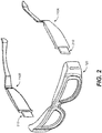
- the glasses 100 include removable temples 110 (e.g., right temple 110A and left temple 110B) that are illustrated in the removed position in Fig. 2 .
- removable temples 110 e.g., right temple 110A and left temple 110B
- the removable temples 110 include, for example, an attachment mechanism.
- An attachment mechanism 210 is shown which comprises an insert tab that fits into a receptacle (not shown) of the lens frame 120.
- the attachment mechanism securely fits into the receptacle and is not easily or casually removed by a user, but do remove prior to breakage when force is applied in a remove the temple motion (e.g., pulling the temple back from the lens frames 120 in this example).
- the removable temples allow for repair and by maintaining a fixed position help provide security from accidental (or intentional) folding and placement in a user's pocket when exiting a theater (since this embodiment does not fold).
- Other embodiment may include a similar attachment/detachment mechanism and include a hinge or other temple folding method (e.g., glasses intended for purchase by a user).
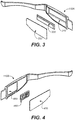
- Fig. 3 is a drawing of a temple (left temple 110A in this example) with a sensor tag (e.g., radio microchip, sensormatic tag, etc) according to a comparative example.
- the sensor tag may be utilized, for example, for accounting and other management aspects of the glasses. Example management and other aspects may be found in, for example, Hovanky et. al., US Patent Application serial No. 61/320,502 , (Attorney Docket Number D10019, titled "3D Glasses With RFID And Methods and Devices For Improving Management And Distribution Of Rented Or Leased Commodities"), and Healy et. al., Attorney Docket Number D10017, Serial No. 61/316,277.
- the sensor tag may be, for example, an embedded Sensormatic security tag 330. Cavity 310, cover 330 and adhesive (not shown) are selected to ensure a water tight seal and prevent damage during washing.
- Fig. 4 is a drawing of a temple (right temple 110B in this example) with an RFID tag 460 according to a comparative example.
- the RFID tag may be utilized for counting uses of glasses according to the present invention.
- glasses according to the present invention include both RFID and sensormatic type tags to enable the advantages of both types of devices in a management system unique to theater operations and re-use (either by owner reuse, theater operator re-use, or contractor/theater operator re-use scenarios - e.g., see Healy et al. referenced further above).
- Cavity 450, cover 470 and adhesive are selected to ensure a water tight seal and prevent damage during washing.
- Fig. 5 is a side view drawing of a removable temple 110 according to an embodiment of the present invention.
- the directional arrow 510 illustrates the application of force to remove the temple from the lens frame 120.
- Fig. 6 is a drawing of a lens retention mechanism according to a comparative example.
- the lens retention mechanism includes a lens securing area 610 (e.g., left eye lens securing area 610A, and right eye lens securing area 610B), and snap rings 630.
- Lenses 620 are fit into the lens securing area and held in place by the snap rings 630.
- the snap ring is shown as a full ring that fits around the entire lens securing area, however, other embodiments may use another type of fitting or device to hold the ring in place (e.g., a partial snap ring, securing screws, adhesive, etc.).
- the snap ring may be provided as shown (snapping in from the front of the glasses), or snap in from the rear.
- the illustrated embodiment is a snap in from the front embodiment (The lenses are assembled into the glasses frame from the front of the frame). Structurally, the finished product has the advantage of bringing the lens closer to the user's eyes. With the lenses closer to the user's eyes, a greater field of view is obtained, and reduces reflection (e.g., the user's own reflection) from/on the inside of the lenses. In one embodiment, a field of view is maintained (compared to a rear loaded snap ring) with a smaller lens size.
- a comparative example includes the use of key spaces 650 located at various locations in the lens securing areas 610. Key spaces for the left eye lens and right eye lens securing areas are different. Corresponding keys on the lenses (not shown) and the snap rings (e.g., snap ring keys 660) assure that left eye lenses and right eye lenses are placed in the proper corresponding lens securing area. In other comparative examples, the keys are located on the glasses frames and key spaces on the lenses (or snap rings).
- the lens keys facilitate manufacturing and also provide for easier and more certain field repair. This is particularly important when the 3D projection system for which the glasses are being utilized requires specific filters or other properties in the left or right lenses.
- the present invention includes manufacturing keyed 3D lenses (and/or snap rings), assembling 3D glasses with keyed lenses, and the collection, washing, repair, and distribution of 3D glasses with keyed lenses.
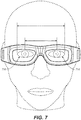
- Fig. 7 is a drawing illustrating inter pupil distances that are optimized in embodiments of the invention.
- the present invention includes one pair of glasses that adapted to fit and operate successfully on either child or adult head sizes. However, the invention also includes glasses prepared specifically for average children head sizes, and which carry a reduced weight.
- the inter pupil distances noted in Fig. 7 are maintained in the "adult" sized glasses of Fig. 1 for both average adult inter pupil distances and average child inter pupil distances. This is further described in Richards et al patent application serial numbers 11/804,602 and 12/530,379 .
- the present invention includes the use of spherically shaped lenses which can enhance the range of the lens' sweet spots (optimized viewing area) 710.
- Such an optimized viewing area can be used to account for differences in variable IPD (inter-pupil distances) such as those encountered between children and adults.
- the optimized sweet spot may be used to make a single sized pair of glasses that is effective for both adult and child viewers, or may be used to increase the sweet spot on either adult specific or child specific glasses.
- the optimized sweet spot of the cylindrical glasses on layered plastic type lenses e.g., spectrally separated lens filters
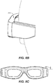
- Fig. 8 is a drawing illustrating a shelf (or lid) 810 according to an embodiment of the present invention.
- the shelf 810 comprises, for example, a lens frame attached device that enables optical alignment of prescription glasses to the viewing areas of the lenses of the 3D glasses. This feature allows the glasses to rest on top of prescription eyewear, bringing the lens sweet spot into optimal position for content viewing. Overall, the dimensions of the glasses support and is designed to fit over 98% of prescription eyewear, with the inner frame designed to 146mm.
- Visual performance of the glasses is a complex relationship between design features including angle (tilt) of the lenses, height of the bridge of the nose, temple position resting on the user's ears and the resultant angle created to the front (frame) of the glasses, for prescription eyewear users, the height of the shelf above the lenses [(e.g., 9.1mm as shown by 830)], and inter-temple dimension for fit over prescription eyewear.
- the sweet spot or optimized area is particularly important with the use of spectrally separated lens filters for 3D viewing.
- the spectrally separated lens filters may be of different varieties (e.g., filters that spectrally separate and specifically adapted to pass light bands blocked by a projection or display mechanism of the same channel - e.g., any of the configurations described in Richards et al. above; or, for example, spectrally separated filters configured to pass narrowband lights in pass areas (high pass, low pass, or band passes) that include a shifting pass area specifically configured to pass the narrow band light when viewed off-axis - e.g., any of the embodiments described in Richards, U.S. patent application serial number 61/452,638 ).
- filters that spectrally separate and specifically adapted to pass light bands blocked by a projection or display mechanism of the same channel - e.g., any of the configurations described in Richards et al. above
- spectrally separated filters configured to pass narrowband lights in pass areas (high pass, low pass, or band passes) that include a shifting pass area specifically configured to pass the narrow band light when
- the shelf may be used in conjunction with blocks, holders, or other mechanisms that help maintain the alignment such as pantoscopic tilt and placement of the optimized viewing areas of the glasses (e.g., 3D glasses) in proper alignment with lenses of the prescription glasses.
- the glasses e.g., 3D glasses
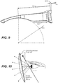
- Fig. 9 is a drawing illustrating a pantoscopic tilt 910 according to an embodiment of the present invention.
- the pantoscopic tilt is approximately 4.5 degrees.
- the preferred pantoscopic tilt for 3D cinema is opposite to that of typical eyewear as shown by Fig. 10 which is a drawing illustrating pantoscopic tilt of typical eyewear.
- the "reversed" pantoscopic tilt according to the invention is utilized to bring the 3D lens sweet spot to an optimal viewing position on the lens.
- the tilt remains the same for child and adult sized glasses.
- the distance 920 between the front of the glasses and the beginning of the arc has been adjusted [(smaller)] to suit children's heads.
- Fig. 11 is a drawing illustrating dimensions according to embodiments of the present invention. Taking into account flexibility of the frame (e.g., dihedral flex) and average child head sizes, the dimensions illustrated have been thoroughly reviewed, tested (including focus group study and actual field tests) and then modified for optimal performance for use by children. The noted dimensions are 1110 being 146mm, 1120 being 147mm, and 1130 being 149.4mm. Approximately as variations can be made and still result in acceptable (even if sub-optimal) performance on average.
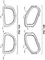
- Fig. 12 is a drawing illustrating lens retaining mechanisms (snap rings) and [textured] areas according to an embodiment of the present invention.
- the illustrated snap rings include keys 660 and the textured areas are designed to minimize unwanted reflections from edges of the snap rings that would otherwise degrade the quality of a 3D cinema experience. Texturing on this area of the snap ring (or on similar areas of other glasses of any design) address the unwanted reflection issue which only becomes apparent with use of glasses in a cinema environment (or other environments using glasses in dark areas with some sort of bright lighting or display being viewed), that is reflection from edges of a lens retention device (or perhaps even edges of lenses depending on the design of the glasses) through the lens and into the viewing path. Texturing is utilized in the present invention, but other mechanisms may be utilized (e.g., absorptive materials, non-reflective surfaces, etc.).
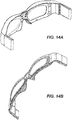
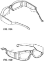
- Figs. 13 , 14 , 15 , and 16 are drawings illustrating [smooth] areas on glasses according to embodiments of the present invention.
- the smooth areas are in contrast to the non-reflective areas previously discussed. Most notably, the smooth areas function to help keep the glasses clean. Since the glasses come in contact with users from the general public (and privately owned models are used by their owners), they must be cleaned. Here, the areas of typical contact with the general public are smooth, which enhances cleaning of the areas that will likely pick up the largest amount of contaminants. The smooth areas may also reduce the amount of detergent and wash time necessary to effectively clean the glasses after every use.
- [smooth] areas 1310 comprise, for example, polished external surfaces of the snap rings -- as mounted on the frame - which are aesthetic appealing and easy to clean.
- smooth areas 1620 comprise, for example, Polished surfaces of the temples improve bonding strength and sealing integrity of the pressure-sensitive adhesive used to adhere the cover labels to the body of the temples.
Landscapes
- Physics & Mathematics (AREA)
- Health & Medical Sciences (AREA)
- General Physics & Mathematics (AREA)
- Optics & Photonics (AREA)
- Ophthalmology & Optometry (AREA)
- General Health & Medical Sciences (AREA)
- Acoustics & Sound (AREA)
- Otolaryngology (AREA)
- Eyeglasses (AREA)
Description
- The present invention relates to eyewear and more particularly to 3D eyewear and 3D eyewear designated for repeated use in cinema theater operations.
- Eyewear for use in 3D theater and other operations are known. For example,
Richards et al, US Patent No. 7,784,938 describes eyewear for 3D theater operations. Other types of eyewear for 3D theater operations are also known, including disposable and recyclable glasses that are less environmentally friendly than glasses designated for washing and re-use. - Methods for 3D stereoscopic projection include Anaglyph, Linear Polarization, Circular Polarization, Shutter Glasses, and Spectral Separation. Anaglyph is the oldest technology, and provides left/right eye separation by filtering the light through a two color filter, commonly red for one eye, and cyan for the other eye. At the projector, the left eye image is (commonly) filtered through a red filter, and the right image filtered through a cyan filter. The eyewear consists of a red filter for the left eye, and a cyan filter for the right eye. This method works best for black and white original images, and is not well suited for color images.
- Linear Polarization 3D provides separation at the projector by filtering the left eye through a linear polarizer (commonly) oriented vertically, and filtering the right eye image through a linear polarizer oriented horizontally. The eyewear consists of a vertically oriented linear polarizer for the left eye and a horizontally oriented polarizer for the right eye. The projection screen must be of the polarization preserving type, commonly referred to as a "silver screen" because of its distinctive color. Linear Polarization allows a full color image to be displayed with little color distortion. It has several problems, these include the need for a silver screen which is expensive, fragile, and not uniform. Another problem is that the viewer must keep his head oriented vertically to avoid crosstalk from one eye to another.
- Circular Polarization 3D was invented to address the problem of requiring the viewer to keep his head oriented vertically. Circular Polarization provides separation at the projector by filtering the left eye image through a (commonly) left handed circular polarizer, and filtering the right eye image through a right handed circular polarizer. The eyewear consists of a left handed circular polarizer for the left eye and a right handed circular polarizer for the right eye. A silver screen is also needed for this approach.
- Shutter Glasses provides separation by multiplexing the left and right images in time. A filter for separation at the projector is not required. The eyewear consists of Shutter Glasses. These are active glasses that electronically shutter the lens in synchrony with the projector frame rate. The left eye image is first displayed, followed by the right eye image etc. Since having a direct wired connection to the Glasses in a theatre is impractical, a wireless or infrared signaling method is used to provide a timing reference for the left/right eye shuttering. This method requires an IR or RF transmitter in the auditorium. The Shutter Glasses are expensive and hard to clean, require batteries that must be frequently replaced, and are limited in their switching rate. Shutter glasses are only practical for use with D-Cinema or other electronic projection systems since very few film projectors provide the signal required to synchronize the shutter glasses with the frame rate. The method does not require a silver screen.
- Spectral Separation provides separation at the projector by filtering the left and right eye spectrally. The system differs from anaglyph in that the filters for the left and right eye each pass a portion of the red, green, and blue spectrum, providing for a full color image. The band pass spectrum of the left eye filter is complementary to the band pass spectrum of the right eye filter. The eyewear consists of filters with the same general spectral characteristics as are used in the projector. While this method provides a full color image, it requires color compensation to make the colors in the left and right eye match the colors that were present in the original image, and there may be a small reduction in the color gamut compared to the gamut of the projector.
- All of the above methods for providing left/right eye separation for a 3D Stereoscopic presentation can be used with either two projectors (one for the left eye and one for the right eye), or may be used with a single D-Cinema projector system. In the dual projection system, the projection filter is usually static, and may be located in front of the projection lens or inside the projector. In a single D-Cinema projector system, the left and right images are time multiplexed. Except for the Shutter Glasses case where no projection filters are required, this means that the projection filters must change at the L/R multiplex frequency. This can be done with either a filter wheel in the projector synchronized to the multiplex frequency, or with an electronically switched filter.
- A search report was issued by the European Patent Office in connection with the present application. The search report identified: Chines patent application publication no.
101840075 , which discloses a pair of spectacles that comprises lenses, an outer frame, and lens feet pivoted on the two sides of the outer frame; andU.S. patent application publication no. 2011/187986 , which discloses a pair of eyeglasses that includes a pair of lenses, an outer border, and a pair of temple arms. Further prior art includeUS2011032476 (3D glasses),US2006244897 (rims with padding elements),CN101840075 andFR1126329 - The invention is defined by the claims.
The present inventors have realized the need for improvements in eyewear and particularly for improvements in eyewear that is re-used and even more particularly for eyewear in 3D cinema theater operations. - The present disclosure provides 3D viewing glasses as recited in claim 1. Optional features are recited in the dependent claims. These and other features of the invention may be practiced alone or, preferably, in combination with other features presented herein.
- A more complete appreciation of the invention and many of the attendant advantages thereof will be readily obtained as the same becomes better understood by reference to the following detailed description when considered in connection with the accompanying drawings, wherein:
-
Fig. 1 is a drawing of 3D viewing glasses according to an embodiment of the present invention; -
Fig. 2 is a drawing illustrating removable temples according to an embodiment of the present invention; -
Fig. 3 is a drawing of an [RFID] temple according to a comparative example; -
Fig. 4 is a drawing of a [radio microchip] temple according to a comparative example; -
Fig. 5 is a side view drawing of a removable temple according to an embodiment of the present invention; -
Fig. 6 is a drawing of a lens retention mechanism according to a comparative example; -
Fig. 7 is a drawing illustrating inter pupil distance that is optimized in embodiments of the invention; -
Fig. 8 is a drawing illustrating a shelf according to an embodiment of the present invention; -
Fig. 9 is a drawing illustrating a pantoscopic tilt according to an embodiment of the present invention; -
Fig. 10 is a drawing illustrating pantoscopic tilt for typical eyewear; -
Fig. 11 is a drawing illustrating dimensions according to embodiments of the present invention; -
Fig. 12 is a drawing illustrating lens retaining mechanisms and [textured] areas according to an embodiment of the present invention; -
Fig. 13 is a drawing illustrating [smooth] areas on glasses according to embodiments of the present invention; -
Fig. 14 is a drawing illustrating [smooth] areas on glasses according to embodiments of the present invention; -
Fig. 15 is a drawing illustrating [smooth] areas on glasses according to embodiments of the present invention; and -
Fig. 16 is a drawing illustrating smooth areas on glasses according to embodiments of the present invention. - Referring now to the drawings, wherein like reference numerals designate identical or corresponding parts, and more particularly to
Fig. 1 thereof, there is illustrated3D viewing glasses 100 according to an embodiment of the present invention. Theglasses 100 include removable temples 110 (e.g.,right temple 110A and lefttemple 110B) that are illustrated in the removed position inFig. 2 . - The
removable temples 110 include, for example, an attachment mechanism. Anattachment mechanism 210 is shown which comprises an insert tab that fits into a receptacle (not shown) of thelens frame 120. Preferably, the attachment mechanism securely fits into the receptacle and is not easily or casually removed by a user, but do remove prior to breakage when force is applied in a remove the temple motion (e.g., pulling the temple back from the lens frames 120 in this example). The removable temples allow for repair and by maintaining a fixed position help provide security from accidental (or intentional) folding and placement in a user's pocket when exiting a theater (since this embodiment does not fold). Other embodiment may include a similar attachment/detachment mechanism and include a hinge or other temple folding method (e.g., glasses intended for purchase by a user). -
Fig. 3 is a drawing of a temple (lefttemple 110A in this example) with a sensor tag (e.g., radio microchip, sensormatic tag, etc) according to a comparative example. The sensor tag may be utilized, for example, for accounting and other management aspects of the glasses. Example management and other aspects may be found in, for example, Hovanky et. al.,US Patent Application serial No. 61/320,502 Sensormatic security tag 330.Cavity 310,cover 330 and adhesive (not shown) are selected to ensure a water tight seal and prevent damage during washing. -
Fig. 4 is a drawing of a temple (right temple 110B in this example) with anRFID tag 460 according to a comparative example. The RFID tag may be utilized for counting uses of glasses according to the present invention. Preferably, glasses according to the present invention include both RFID and sensormatic type tags to enable the advantages of both types of devices in a management system unique to theater operations and re-use (either by owner reuse, theater operator re-use, or contractor/theater operator re-use scenarios - e.g., see Healy et al. referenced further above). As shown inFig. 4 ,Cavity 450,cover 470 and adhesive (not shown) are selected to ensure a water tight seal and prevent damage during washing. -
Fig. 5 is a side view drawing of aremovable temple 110 according to an embodiment of the present invention. Thedirectional arrow 510 illustrates the application of force to remove the temple from thelens frame 120. -
Fig. 6 is a drawing of a lens retention mechanism according to a comparative example. The lens retention mechanism includes a lens securing area 610 (e.g., left eyelens securing area 610A, and right eyelens securing area 610B), and snap rings 630. Lenses 620 are fit into the lens securing area and held in place by the snap rings 630. The snap ring is shown as a full ring that fits around the entire lens securing area, however, other embodiments may use another type of fitting or device to hold the ring in place (e.g., a partial snap ring, securing screws, adhesive, etc.). - The snap ring may be provided as shown (snapping in from the front of the glasses), or snap in from the rear. The illustrated embodiment is a snap in from the front embodiment (The lenses are assembled into the glasses frame from the front of the frame). Structurally, the finished product has the advantage of bringing the lens closer to the user's eyes. With the lenses closer to the user's eyes, a greater field of view is obtained, and reduces reflection (e.g., the user's own reflection) from/on the inside of the lenses. In one embodiment, a field of view is maintained (compared to a rear loaded snap ring) with a smaller lens size.
- A comparative example includes the use of
key spaces 650 located at various locations in the lens securing areas 610. Key spaces for the left eye lens and right eye lens securing areas are different. Corresponding keys on the lenses (not shown) and the snap rings (e.g., snap ring keys 660) assure that left eye lenses and right eye lenses are placed in the proper corresponding lens securing area. In other comparative examples, the keys are located on the glasses frames and key spaces on the lenses (or snap rings). - The lens keys facilitate manufacturing and also provide for easier and more certain field repair. This is particularly important when the 3D projection system for which the glasses are being utilized requires specific filters or other properties in the left or right lenses. Thus, the present invention includes manufacturing keyed 3D lenses (and/or snap rings), assembling 3D glasses with keyed lenses, and the collection, washing, repair, and distribution of 3D glasses with keyed lenses.
-
Fig. 7 is a drawing illustrating inter pupil distances that are optimized in embodiments of the invention. The present invention includes one pair of glasses that adapted to fit and operate successfully on either child or adult head sizes. However, the invention also includes glasses prepared specifically for average children head sizes, and which carry a reduced weight. The inter pupil distances noted inFig. 7 are maintained in the "adult" sized glasses ofFig. 1 for both average adult inter pupil distances and average child inter pupil distances. This is further described in Richards et al patent application serial numbers11/804,602 12/530,379 - In addition, the present invention includes the use of spherically shaped lenses which can enhance the range of the lens' sweet spots (optimized viewing area) 710. Such an optimized viewing area can be used to account for differences in variable IPD (inter-pupil distances) such as those encountered between children and adults. Accordingly, the optimized sweet spot may be used to make a single sized pair of glasses that is effective for both adult and child viewers, or may be used to increase the sweet spot on either adult specific or child specific glasses. The optimized sweet spot of the cylindrical glasses on layered plastic type lenses (e.g., spectrally separated lens filters) may have, for example, an aperture of 1066.2 mm2 and a Ratio (useable area/clear aperture area) of 0.564.
-
Fig. 8 is a drawing illustrating a shelf (or lid) 810 according to an embodiment of the present invention. Theshelf 810 comprises, for example, a lens frame attached device that enables optical alignment of prescription glasses to the viewing areas of the lenses of the 3D glasses. This feature allows the glasses to rest on top of prescription eyewear, bringing the lens sweet spot into optimal position for content viewing. Overall, the dimensions of the glasses support and is designed to fit over 98% of prescription eyewear, with the inner frame designed to 146mm. - Visual performance of the glasses is a complex relationship between design features including angle (tilt) of the lenses, height of the bridge of the nose, temple position resting on the user's ears and the resultant angle created to the front (frame) of the glasses, for prescription eyewear users, the height of the shelf above the lenses [(e.g., 9.1mm as shown by 830)], and inter-temple dimension for fit over prescription eyewear. The sweet spot or optimized area is particularly important with the use of spectrally separated lens filters for 3D viewing. The spectrally separated lens filters may be of different varieties (e.g., filters that spectrally separate and specifically adapted to pass light bands blocked by a projection or display mechanism of the same channel - e.g., any of the configurations described in Richards et al. above; or, for example, spectrally separated filters configured to pass narrowband lights in pass areas (high pass, low pass, or band passes) that include a shifting pass area specifically configured to pass the narrow band light when viewed off-axis - e.g., any of the embodiments described in Richards,
U.S. patent application serial number 61/452,638 - In one embodiment, the shelf may be used in conjunction with blocks, holders, or other mechanisms that help maintain the alignment such as pantoscopic tilt and placement of the optimized viewing areas of the glasses (e.g., 3D glasses) in proper alignment with lenses of the prescription glasses.
-
Fig. 9 is a drawing illustrating apantoscopic tilt 910 according to an embodiment of the present invention. In this example the pantoscopic tilt is approximately 4.5 degrees. Note that the preferred pantoscopic tilt for 3D cinema is opposite to that of typical eyewear as shown byFig. 10 which is a drawing illustrating pantoscopic tilt of typical eyewear. The "reversed" pantoscopic tilt according to the invention is utilized to bring the 3D lens sweet spot to an optimal viewing position on the lens. - The tilt remains the same for child and adult sized glasses. The
distance 920 between the front of the glasses and the beginning of the arc has been adjusted [(smaller)] to suit children's heads. -
Fig. 11 is a drawing illustrating dimensions according to embodiments of the present invention. Taking into account flexibility of the frame (e.g., dihedral flex) and average child head sizes, the dimensions illustrated have been thoroughly reviewed, tested (including focus group study and actual field tests) and then modified for optimal performance for use by children. The noted dimensions are 1110 being 146mm, 1120 being 147mm, and 1130 being 149.4mm. Approximately as variations can be made and still result in acceptable (even if sub-optimal) performance on average. -
Fig. 12 is a drawing illustrating lens retaining mechanisms (snap rings) and [textured] areas according to an embodiment of the present invention. The illustrated snap rings includekeys 660 and the textured areas are designed to minimize unwanted reflections from edges of the snap rings that would otherwise degrade the quality of a 3D cinema experience. Texturing on this area of the snap ring (or on similar areas of other glasses of any design) address the unwanted reflection issue which only becomes apparent with use of glasses in a cinema environment (or other environments using glasses in dark areas with some sort of bright lighting or display being viewed), that is reflection from edges of a lens retention device (or perhaps even edges of lenses depending on the design of the glasses) through the lens and into the viewing path. Texturing is utilized in the present invention, but other mechanisms may be utilized (e.g., absorptive materials, non-reflective surfaces, etc.). -
Figs. 13 ,14 ,15 , and16 are drawings illustrating [smooth] areas on glasses according to embodiments of the present invention. The smooth areas are in contrast to the non-reflective areas previously discussed. Most notably, the smooth areas function to help keep the glasses clean. Since the glasses come in contact with users from the general public (and privately owned models are used by their owners), they must be cleaned. Here, the areas of typical contact with the general public are smooth, which enhances cleaning of the areas that will likely pick up the largest amount of contaminants. The smooth areas may also reduce the amount of detergent and wash time necessary to effectively clean the glasses after every use. - In
Fig. 13 , [smooth]areas 1310 comprise, for example, polished external surfaces of the snap rings -- as mounted on the frame - which are aesthetic appealing and easy to clean. InFig. 16 , smooth areas 1620 comprise, for example, Polished surfaces of the temples improve bonding strength and sealing integrity of the pressure-sensitive adhesive used to adhere the cover labels to the body of the temples.
Claims (11)
- 3D viewing glasses comprising:removable temples (110) with an attachment mechanism; anda retaining mechanism for retaining lenses, the retaining mechanism comprising a) edges from which light could be reflected into a viewing path of the wearer, and b) areas that typically come into contact with the wearer, wherein said edges from which light could be reflected into a viewing path of the wearer comprise non-reflective surfaces, and wherein said areas that typically come into contact with the wearer comprise reflective surfaces (1310, 1620) that are smoother than the non-reflective surfaces and function to help keep the glasses clean,wherein the retaining mechanism comprises snap rings for retaining lenses and the edges from which light could be reflected into a viewing path of the wearer comprise edges of the snap rings.
- The 3D viewing glasses according to Claim 1, wherein the reflective surfaces comprise polished external surfaces of the snap rings.
- The 3D viewing glasses according to any preceding Claim, wherein at least one of the removable temples comprise a pin configured to be inserted into a receptacle on a frame of the viewing glasses.
- The 3D viewing glasses according to Claim 1, wherein the non-reflective surfaces are textured surfaces.
- The 3D viewing glasses according to any preceding Claim further comprising a lens frame and spectrally separated lenses and a shelf at a top of the lens frame.
- The 3D viewing glasses according to Claim 5, wherein the shelf is configured to rest on prescription glasses and optically align prescription glasses to the viewing areas of the lenses.
- The 3D viewing glasses according to Claim 5, wherein the shelf is configured to rest on top of prescription eyewear with a pantoscopic tilt of 4.5 degrees, thereby bringing a sweet spot of the lenses into an optimal position for content viewing.
- The 3D viewing glasses according to Claim 5, wherein an inner part of the lens frame of the 3D viewing glasses is 146 mm wide.
- The 3D viewing glasses according to Claim 5, wherein the spectrally separated lens filters are configured to spectrally separate narrow band lights in passbands that include a shifting pass area configured to pass the narrow band light when viewed off-axis.
- The 3D viewing glasses according to any preceding Claim wherein the inter pupil distances of the glasses are maintained for both average adult inter pupil distances and average child inter pupil distances, so that the glasses fit and operate on either child or adult head sizes.
- The 3D viewing glasses according to any preceding Claim wherein the lens frame is flexible so that the glasses fit and operate on either child or adult head sizes.
Applications Claiming Priority (1)
| Application Number | Priority Date | Filing Date | Title |
|---|---|---|---|
| US201161449635P | 2011-03-05 | 2011-03-05 |
Publications (3)
| Publication Number | Publication Date |
|---|---|
| EP2498118A2 EP2498118A2 (en) | 2012-09-12 |
| EP2498118A3 EP2498118A3 (en) | 2012-12-05 |
| EP2498118B1 true EP2498118B1 (en) | 2019-07-31 |
Family
ID=45874651
Family Applications (1)
| Application Number | Title | Priority Date | Filing Date |
|---|---|---|---|
| EP12157302.6A Active EP2498118B1 (en) | 2011-03-05 | 2012-02-28 | 3D Eyeglasses for personal and commercial use including reuse in 3d theater and other repeated operations |
Country Status (3)
| Country | Link |
|---|---|
| US (1) | US9766479B2 (en) |
| EP (1) | EP2498118B1 (en) |
| CN (1) | CN102681178B (en) |
Families Citing this family (50)
| Publication number | Priority date | Publication date | Assignee | Title |
|---|---|---|---|---|
| US20110047682A1 (en) * | 2009-08-25 | 2011-03-03 | Arman Hedayat | Protective Eyewear Device With Lateral Eye Access and Quick Release Mechanism for Interchanging Lenses |
| JP5865848B2 (en) | 2010-03-15 | 2016-02-17 | ドルビー ラボラトリーズ ライセンシング コーポレイション | 3D glasses and related systems |
| GB2536650A (en) | 2015-03-24 | 2016-09-28 | Augmedics Ltd | Method and system for combining video-based and optic-based augmented reality in a near eye display |
| USD847893S1 (en) * | 2016-02-23 | 2019-05-07 | Esight Corporation | Vision apparatus comprising eyewear frame and demountable display |
| CN105892065B (en) * | 2016-07-08 | 2018-08-17 | 邹泳峰 | A kind of VR glasses |
| CN109923444B (en) | 2016-09-30 | 2023-11-28 | 杜比实验室特许公司 | 3D glasses adapted to facial geometry |
| USD835707S1 (en) | 2017-04-12 | 2018-12-11 | Dolby Laboratories Licensing Corporation | 3D glasses |
| WO2018229688A1 (en) | 2017-06-15 | 2018-12-20 | 3M Innovative Properties Company | Vision-protective headgear with automatic darkening filter comprising an array of switchable shutters |
| US10747020B2 (en) * | 2017-12-06 | 2020-08-18 | VISCOTTA INDUSTRIES S.p.A. | Hinge for eyeglasses |
| US12458411B2 (en) | 2017-12-07 | 2025-11-04 | Augmedics Ltd. | Spinous process clamp |
| US12521201B2 (en) | 2017-12-07 | 2026-01-13 | Augmedics Ltd. | Spinous process clamp |
| USD872793S1 (en) | 2018-02-15 | 2020-01-14 | Dolby Laboratories Licensing Corporation | Eyeglasses |
| CN114721175B (en) | 2018-03-23 | 2025-05-27 | 斯纳普公司 | Eyewear device hinge assembly |
| USD864284S1 (en) * | 2018-04-13 | 2019-10-22 | Ningbo Geostar Photoelectric Technology Co., Ltd. | Digital welding goggle |
| US11980507B2 (en) | 2018-05-02 | 2024-05-14 | Augmedics Ltd. | Registration of a fiducial marker for an augmented reality system |
| CN108471529B (en) * | 2018-06-11 | 2020-09-25 | 河海大学文天学院 | 3D glasses with adjustable degree of myopia, glasses management system and using method thereof |
| USD876531S1 (en) | 2018-06-29 | 2020-02-25 | Reyewear Acquisition, Inc. | Eyewear |
| USD874555S1 (en) * | 2018-06-29 | 2020-02-04 | Revision Military Inc. | Eyewear temple bar |
| USD874554S1 (en) | 2018-07-12 | 2020-02-04 | Reyewear Acquisition, Inc. | Eyewear |
| USD866651S1 (en) * | 2018-07-12 | 2019-11-12 | Revision Military Inc. | Eyewear temple bar |
| JP1635250S (en) * | 2018-09-28 | 2019-07-01 | ||
| US11766296B2 (en) | 2018-11-26 | 2023-09-26 | Augmedics Ltd. | Tracking system for image-guided surgery |
| JP2020161923A (en) * | 2019-03-26 | 2020-10-01 | セイコーエプソン株式会社 | Wearable display device |
| EP3741333A1 (en) | 2019-05-23 | 2020-11-25 | 3M Innovative Properties Company | Darkening filter comprising a non-uniform pattern of switchable shutters |
| USD1005380S1 (en) * | 2019-07-23 | 2023-11-21 | Ckmc Enterprises, Ltd. | Eyeglass clip |
| US12178666B2 (en) | 2019-07-29 | 2024-12-31 | Augmedics Ltd. | Fiducial marker |
| USD923690S1 (en) * | 2019-12-20 | 2021-06-29 | Bose Corporation | Audio eyeglasses |
| USD933736S1 (en) * | 2019-12-20 | 2021-10-19 | Bose Corporation | Audio eyeglasses |
| USD923693S1 (en) * | 2019-12-20 | 2021-06-29 | Bose Corporation | Audio eyeglasses |
| USD923691S1 (en) * | 2019-12-20 | 2021-06-29 | Bose Corporation | Audio eyeglasses |
| USD923692S1 (en) * | 2019-12-20 | 2021-06-29 | Bose Corporation | Audio eyeglasses |
| US11382712B2 (en) | 2019-12-22 | 2022-07-12 | Augmedics Ltd. | Mirroring in image guided surgery |
| US11249312B2 (en) | 2020-05-01 | 2022-02-15 | Google Llc | Color-corrected curved optical see-through thin lightguide with large field of view in eyewear formfactor |
| US11747647B2 (en) * | 2020-05-18 | 2023-09-05 | Edward Chay | Endpiece assemblies for eyeglasses |
| US11389252B2 (en) | 2020-06-15 | 2022-07-19 | Augmedics Ltd. | Rotating marker for image guided surgery |
| USD963032S1 (en) * | 2020-08-10 | 2022-09-06 | Yiwu Shangwei Import & Export Co., Ltd. | Baby sunglasses with strap |
| USD964455S1 (en) * | 2020-08-31 | 2022-09-20 | Xiaolu Lu | Baby sunglasses with strap |
| USD964454S1 (en) * | 2020-08-31 | 2022-09-20 | Yiwu Shangwei Import & Export Co., Ltd. | Baby sunglasses with strap |
| US12502163B2 (en) | 2020-09-09 | 2025-12-23 | Augmedics Ltd. | Universal tool adapter for image-guided surgery |
| US12239385B2 (en) | 2020-09-09 | 2025-03-04 | Augmedics Ltd. | Universal tool adapter |
| JP1688745S (en) * | 2020-10-26 | 2021-06-28 | ||
| IT202100010256A1 (en) * | 2021-04-22 | 2022-10-22 | Andrea Drigo | ANTI-THEFT AND TRACKING DEVICE |
| USD969206S1 (en) * | 2021-07-14 | 2022-11-08 | Yiwu Shangwei Import & Export Co., Ltd. | Baby sunglasses with strap |
| US12150821B2 (en) | 2021-07-29 | 2024-11-26 | Augmedics Ltd. | Rotating marker and adapter for image-guided surgery |
| EP4388734A4 (en) | 2021-08-18 | 2025-05-07 | Augmedics Ltd. | Stereoscopic display and digital loupe for augmented-reality near-eye display |
| USD1028069S1 (en) * | 2022-02-15 | 2024-05-21 | Christian Dior Couture | Spectacles |
| WO2023203521A1 (en) | 2022-04-21 | 2023-10-26 | Augmedics Ltd. | Systems and methods for medical image visualization |
| EP4587881A1 (en) * | 2022-09-13 | 2025-07-23 | Augmedics Ltd. | Augmented reality eyewear for image-guided medical intervention |
| DE102023201496A1 (en) * | 2023-02-21 | 2024-08-22 | Robert Bosch Gesellschaft mit beschränkter Haftung | Device for precise alignment of a projection module to a projection surface, method for producing the device |
| US20240288710A1 (en) * | 2023-02-27 | 2024-08-29 | Maurice Matthew Trentel | Systems, methods, and devices for modular eyewear |
Citations (7)
| Publication number | Priority date | Publication date | Assignee | Title |
|---|---|---|---|---|
| US1785929A (en) * | 1928-11-08 | 1930-12-23 | Bausch & Lomb | Ophthalmic mounting |
| GB747235A (en) * | 1953-05-13 | 1956-03-28 | Polaroid Corp | Improvements in or relating to opthalmic devices |
| FR1126329A (en) * | 1955-06-21 | 1956-11-20 | Dolomit | Eyeglass frame for the sun and for sight |
| US4340282A (en) * | 1979-10-13 | 1982-07-20 | Mamoru Murakami | Lens securing device |
| US20060256281A1 (en) * | 2004-12-03 | 2006-11-16 | Li Xin L | Spectacles set with decorative frame |
| CN201477302U (en) * | 2009-05-05 | 2010-05-19 | 黄文泽 | Glasses structure with replaceable foot rest |
| CN101840075A (en) * | 2010-02-02 | 2010-09-22 | 鸿富锦精密工业(深圳)有限公司 | Spectacles |
Family Cites Families (29)
| Publication number | Priority date | Publication date | Assignee | Title |
|---|---|---|---|---|
| US3060804A (en) * | 1959-08-21 | 1962-10-30 | Rogers Nathan Jay | Adjustable eyeglass hinge |
| US3691565A (en) * | 1970-11-25 | 1972-09-19 | Omnitech Inc | Flight deck goggle |
| IT1033888B (en) * | 1975-05-26 | 1979-08-10 | Ottica Snc | EASY INTERCHANGEABLE FIXING SYSTEM FOR GLASSES AND RELATIVE SWIMMING GLASSES FOR SPORTS USE IN GENERAL AND UNDERWATER MASKS |
| US4921341A (en) * | 1988-04-19 | 1990-05-01 | Ace Ronald S | Opthalmic lens safety liner |
| US5218386A (en) | 1991-06-19 | 1993-06-08 | Levien Raphael L | Eyeglasses with spectral color shift |
| US5243460A (en) * | 1991-11-08 | 1993-09-07 | Elliot Kornberg | Light filtering system for creating perception of stereoscopic images from two-dimensional images and enhancing perception of objects |
| WO1994014285A1 (en) * | 1992-12-10 | 1994-06-23 | Dasso John M | Method and apparatus for generating a three-dimensional effect for two-dimensional images |
| US5638145A (en) * | 1996-02-29 | 1997-06-10 | Oakley, Inc. | Vented eyeglass lens |
| AUPP474898A0 (en) | 1998-07-17 | 1998-08-13 | Sola International Holdings Ltd | Optical lens |
| DE10057102B4 (en) | 2000-11-16 | 2010-09-30 | Infitec Gmbh | Method and arrangement for displaying a multi-dimensional image |
| US6789271B2 (en) * | 2002-03-18 | 2004-09-14 | World Suncare Products, Ltd. | Eye protection |
| US8109629B2 (en) | 2003-10-09 | 2012-02-07 | Ipventure, Inc. | Eyewear supporting electrical components and apparatus therefor |
| US7380936B2 (en) * | 2003-10-09 | 2008-06-03 | Ipventure, Inc. | Eyeglasses with a clock or other electrical component |
| US7255437B2 (en) * | 2003-10-09 | 2007-08-14 | Howell Thomas A | Eyeglasses with activity monitoring |
| US6736504B1 (en) | 2003-04-29 | 2004-05-18 | James Hermsen | Hingeless eyeglasses |
| JP2005107396A (en) * | 2003-10-01 | 2005-04-21 | Seiko Optical Products Co Ltd | Spectacle frame for reverse-surface reflection prevention |
| US20060244897A1 (en) * | 2005-04-27 | 2006-11-02 | Guenther Siegmar W | Modular eyewear |
| WO2007110681A1 (en) | 2006-03-29 | 2007-10-04 | Aten, Inc. | Spectacle frame |
| US20070236809A1 (en) | 2006-04-05 | 2007-10-11 | Barret Lippey | Forming spectral filters |
| US7524053B2 (en) | 2006-05-12 | 2009-04-28 | Real D | 3-D eyewear |
| US8622544B2 (en) | 2006-08-31 | 2014-01-07 | Nike, Inc. | Adjustable spectral transmittance curved lens eyewear |
| US7784938B2 (en) | 2007-05-09 | 2010-08-31 | Dolby Laboratories Licensing Corporation | Method and system for shaped glasses and viewing 3D images |
| TWI539230B (en) | 2007-05-09 | 2016-06-21 | 杜比實驗室特許公司 | 3D image projection and viewing system (1) |
| US7959295B2 (en) * | 2007-05-18 | 2011-06-14 | Dolby Laboratories Licensing Corporation | Spectral separation filters for 3D stereoscopic D-cinema presentation |
| DE202007012236U1 (en) | 2007-08-31 | 2008-09-04 | Infitec Gmbh | System for playing back stereo images |
| USD603445S1 (en) | 2009-03-13 | 2009-11-03 | X6D Limited | 3D glasses |
| US8226227B2 (en) | 2009-09-18 | 2012-07-24 | Sony Corporation | Glasses for image viewing |
| USD626167S1 (en) | 2010-01-07 | 2010-10-26 | Hon Hai Precision Industry Co., Ltd. | 3D spectacles |
| JP5865848B2 (en) | 2010-03-15 | 2016-02-17 | ドルビー ラボラトリーズ ライセンシング コーポレイション | 3D glasses and related systems |
-
2012
- 2012-02-16 US US13/398,437 patent/US9766479B2/en active Active
- 2012-02-28 EP EP12157302.6A patent/EP2498118B1/en active Active
- 2012-03-01 CN CN201210052243.0A patent/CN102681178B/en active Active
Patent Citations (8)
| Publication number | Priority date | Publication date | Assignee | Title |
|---|---|---|---|---|
| US1785929A (en) * | 1928-11-08 | 1930-12-23 | Bausch & Lomb | Ophthalmic mounting |
| GB747235A (en) * | 1953-05-13 | 1956-03-28 | Polaroid Corp | Improvements in or relating to opthalmic devices |
| FR1126329A (en) * | 1955-06-21 | 1956-11-20 | Dolomit | Eyeglass frame for the sun and for sight |
| US4340282A (en) * | 1979-10-13 | 1982-07-20 | Mamoru Murakami | Lens securing device |
| US20060256281A1 (en) * | 2004-12-03 | 2006-11-16 | Li Xin L | Spectacles set with decorative frame |
| CN201477302U (en) * | 2009-05-05 | 2010-05-19 | 黄文泽 | Glasses structure with replaceable foot rest |
| CN101840075A (en) * | 2010-02-02 | 2010-09-22 | 鸿富锦精密工业(深圳)有限公司 | Spectacles |
| US20110187986A1 (en) * | 2010-02-02 | 2011-08-04 | Hong Fu Jin Precision Industry (Shenzhen) Co., Ltd. | Eyeglasses |
Also Published As
| Publication number | Publication date |
|---|---|
| US20120224260A1 (en) | 2012-09-06 |
| CN102681178A (en) | 2012-09-19 |
| CN102681178B (en) | 2017-06-27 |
| EP2498118A2 (en) | 2012-09-12 |
| US9766479B2 (en) | 2017-09-19 |
| EP2498118A3 (en) | 2012-12-05 |
Similar Documents
| Publication | Publication Date | Title |
|---|---|---|
| US9766479B2 (en) | Eyeglasses for personal and commercial use including reuse in 3D theater and other repeated operations | |
| JP6648065B2 (en) | System for projecting and viewing 3D images | |
| US10338399B2 (en) | Method and system for shaped glasses and viewing 3D images | |
| US7524053B2 (en) | 3-D eyewear | |
| CN103221878A (en) | Shutter eyeglasses device | |
| CN101694549A (en) | Spectacles, telescopic spectacles and stereoscopic vision spectacle frame components | |
| HK1174395B (en) | 3d eyeglasses for personal and commercial use including reuse in 3d theater and other repeated operations | |
| US20120062446A1 (en) | Video image viewing glasses and image display system | |
| KR20110118456A (en) | Lens combination for viewing three-dimensional (3D) images with a functional water lens for easy removal | |
| US20130120836A1 (en) | Diopter lens | |
| HK1174395A (en) | 3d eyeglasses for personal and commercial use including reuse in 3d theater and other repeated operations | |
| CN117608100A (en) | Turning mechanisms, frames and spectacles | |
| CN201522597U (en) | Spectacles, telescopic spectacles and dimensional visible image spectacle frame component | |
| KR200464366Y1 (en) | Glasses for watching 3d image | |
| KR102185998B1 (en) | Multifocal film attached to eyeglasses | |
| US20150293367A1 (en) | 3D cover glasses for applying over prescription eyeglasses | |
| KR200464475Y1 (en) | 3d spectacles mounting apparatus | |
| RU2426271C2 (en) | System for demonstrating and viewing 3d images | |
| KR20140010231A (en) | Detatchable type 3d glasses |
Legal Events
| Date | Code | Title | Description |
|---|---|---|---|
| PUAI | Public reference made under article 153(3) epc to a published international application that has entered the european phase |
Free format text: ORIGINAL CODE: 0009012 |
|
| AK | Designated contracting states |
Kind code of ref document: A2 Designated state(s): AL AT BE BG CH CY CZ DE DK EE ES FI FR GB GR HR HU IE IS IT LI LT LU LV MC MK MT NL NO PL PT RO RS SE SI SK SM TR |
|
| AX | Request for extension of the european patent |
Extension state: BA ME |
|
| RIN1 | Information on inventor provided before grant (corrected) |
Inventor name: O'BRIEN, ALAN Inventor name: HEALY, ANDREW Inventor name: HOVANKY, THAO Inventor name: BASLER, BRAD Inventor name: SIJEN, PASCAL Inventor name: FARNAM, JULIAN |
|
| PUAL | Search report despatched |
Free format text: ORIGINAL CODE: 0009013 |
|
| AK | Designated contracting states |
Kind code of ref document: A3 Designated state(s): AL AT BE BG CH CY CZ DE DK EE ES FI FR GB GR HR HU IE IS IT LI LT LU LV MC MK MT NL NO PL PT RO RS SE SI SK SM TR |
|
| AX | Request for extension of the european patent |
Extension state: BA ME |
|
| RIC1 | Information provided on ipc code assigned before grant |
Ipc: G02C 5/22 20060101ALI20121031BHEP Ipc: G02C 5/10 20060101ALI20121031BHEP Ipc: G02B 27/26 20060101ALI20121031BHEP Ipc: G02C 1/06 20060101AFI20121031BHEP Ipc: G02B 27/01 20060101ALI20121031BHEP Ipc: G02C 5/00 20060101ALI20121031BHEP Ipc: G02C 11/06 20060101ALI20121031BHEP |
|
| REG | Reference to a national code |
Ref country code: HK Ref legal event code: DE Ref document number: 1174395 Country of ref document: HK |
|
| 17P | Request for examination filed |
Effective date: 20130605 |
|
| RBV | Designated contracting states (corrected) |
Designated state(s): AL AT BE BG CH CY CZ DE DK EE ES FI FR GB GR HR HU IE IS IT LI LT LU LV MC MK MT NL NO PL PT RO RS SE SI SK SM TR |
|
| RAP1 | Party data changed (applicant data changed or rights of an application transferred) |
Owner name: DOLBY LABORATORIES LICENSING CORPORATION |
|
| STAA | Information on the status of an ep patent application or granted ep patent |
Free format text: STATUS: EXAMINATION IS IN PROGRESS |
|
| 17Q | First examination report despatched |
Effective date: 20170503 |
|
| RIC1 | Information provided on ipc code assigned before grant |
Ipc: G02B 5/20 20060101ALN20190328BHEP Ipc: G02B 27/26 20060101ALI20190328BHEP Ipc: G02B 27/01 20060101ALI20190328BHEP Ipc: G02C 5/22 20060101ALI20190328BHEP Ipc: G02C 5/10 20060101ALI20190328BHEP Ipc: G02C 11/00 20060101ALN20190328BHEP Ipc: G02C 7/16 20060101ALI20190328BHEP Ipc: G02C 1/06 20060101AFI20190328BHEP Ipc: G02C 5/14 20060101ALI20190328BHEP |
|
| GRAP | Despatch of communication of intention to grant a patent |
Free format text: ORIGINAL CODE: EPIDOSNIGR1 |
|
| STAA | Information on the status of an ep patent application or granted ep patent |
Free format text: STATUS: GRANT OF PATENT IS INTENDED |
|
| INTG | Intention to grant announced |
Effective date: 20190506 |
|
| GRAS | Grant fee paid |
Free format text: ORIGINAL CODE: EPIDOSNIGR3 |
|
| GRAA | (expected) grant |
Free format text: ORIGINAL CODE: 0009210 |
|
| STAA | Information on the status of an ep patent application or granted ep patent |
Free format text: STATUS: THE PATENT HAS BEEN GRANTED |
|
| AK | Designated contracting states |
Kind code of ref document: B1 Designated state(s): AL AT BE BG CH CY CZ DE DK EE ES FI FR GB GR HR HU IE IS IT LI LT LU LV MC MK MT NL NO PL PT RO RS SE SI SK SM TR |
|
| REG | Reference to a national code |
Ref country code: CH Ref legal event code: EP Ref country code: GB Ref legal event code: FG4D |
|
| REG | Reference to a national code |
Ref country code: AT Ref legal event code: REF Ref document number: 1161534 Country of ref document: AT Kind code of ref document: T Effective date: 20190815 |
|
| REG | Reference to a national code |
Ref country code: IE Ref legal event code: FG4D |
|
| REG | Reference to a national code |
Ref country code: DE Ref legal event code: R096 Ref document number: 602012062392 Country of ref document: DE |
|
| REG | Reference to a national code |
Ref country code: NL Ref legal event code: MP Effective date: 20190731 |
|
| REG | Reference to a national code |
Ref country code: LT Ref legal event code: MG4D |
|
| REG | Reference to a national code |
Ref country code: AT Ref legal event code: MK05 Ref document number: 1161534 Country of ref document: AT Kind code of ref document: T Effective date: 20190731 |
|
| PG25 | Lapsed in a contracting state [announced via postgrant information from national office to epo] |
Ref country code: BG Free format text: LAPSE BECAUSE OF FAILURE TO SUBMIT A TRANSLATION OF THE DESCRIPTION OR TO PAY THE FEE WITHIN THE PRESCRIBED TIME-LIMIT Effective date: 20191031 Ref country code: NO Free format text: LAPSE BECAUSE OF FAILURE TO SUBMIT A TRANSLATION OF THE DESCRIPTION OR TO PAY THE FEE WITHIN THE PRESCRIBED TIME-LIMIT Effective date: 20191031 Ref country code: AT Free format text: LAPSE BECAUSE OF FAILURE TO SUBMIT A TRANSLATION OF THE DESCRIPTION OR TO PAY THE FEE WITHIN THE PRESCRIBED TIME-LIMIT Effective date: 20190731 Ref country code: NL Free format text: LAPSE BECAUSE OF FAILURE TO SUBMIT A TRANSLATION OF THE DESCRIPTION OR TO PAY THE FEE WITHIN THE PRESCRIBED TIME-LIMIT Effective date: 20190731 Ref country code: SE Free format text: LAPSE BECAUSE OF FAILURE TO SUBMIT A TRANSLATION OF THE DESCRIPTION OR TO PAY THE FEE WITHIN THE PRESCRIBED TIME-LIMIT Effective date: 20190731 Ref country code: LT Free format text: LAPSE BECAUSE OF FAILURE TO SUBMIT A TRANSLATION OF THE DESCRIPTION OR TO PAY THE FEE WITHIN THE PRESCRIBED TIME-LIMIT Effective date: 20190731 Ref country code: HR Free format text: LAPSE BECAUSE OF FAILURE TO SUBMIT A TRANSLATION OF THE DESCRIPTION OR TO PAY THE FEE WITHIN THE PRESCRIBED TIME-LIMIT Effective date: 20190731 Ref country code: FI Free format text: LAPSE BECAUSE OF FAILURE TO SUBMIT A TRANSLATION OF THE DESCRIPTION OR TO PAY THE FEE WITHIN THE PRESCRIBED TIME-LIMIT Effective date: 20190731 Ref country code: PT Free format text: LAPSE BECAUSE OF FAILURE TO SUBMIT A TRANSLATION OF THE DESCRIPTION OR TO PAY THE FEE WITHIN THE PRESCRIBED TIME-LIMIT Effective date: 20191202 |
|
| PG25 | Lapsed in a contracting state [announced via postgrant information from national office to epo] |
Ref country code: ES Free format text: LAPSE BECAUSE OF FAILURE TO SUBMIT A TRANSLATION OF THE DESCRIPTION OR TO PAY THE FEE WITHIN THE PRESCRIBED TIME-LIMIT Effective date: 20190731 Ref country code: GR Free format text: LAPSE BECAUSE OF FAILURE TO SUBMIT A TRANSLATION OF THE DESCRIPTION OR TO PAY THE FEE WITHIN THE PRESCRIBED TIME-LIMIT Effective date: 20191101 Ref country code: RS Free format text: LAPSE BECAUSE OF FAILURE TO SUBMIT A TRANSLATION OF THE DESCRIPTION OR TO PAY THE FEE WITHIN THE PRESCRIBED TIME-LIMIT Effective date: 20190731 Ref country code: LV Free format text: LAPSE BECAUSE OF FAILURE TO SUBMIT A TRANSLATION OF THE DESCRIPTION OR TO PAY THE FEE WITHIN THE PRESCRIBED TIME-LIMIT Effective date: 20190731 Ref country code: IS Free format text: LAPSE BECAUSE OF FAILURE TO SUBMIT A TRANSLATION OF THE DESCRIPTION OR TO PAY THE FEE WITHIN THE PRESCRIBED TIME-LIMIT Effective date: 20191130 Ref country code: AL Free format text: LAPSE BECAUSE OF FAILURE TO SUBMIT A TRANSLATION OF THE DESCRIPTION OR TO PAY THE FEE WITHIN THE PRESCRIBED TIME-LIMIT Effective date: 20190731 |
|
| PG25 | Lapsed in a contracting state [announced via postgrant information from national office to epo] |
Ref country code: TR Free format text: LAPSE BECAUSE OF FAILURE TO SUBMIT A TRANSLATION OF THE DESCRIPTION OR TO PAY THE FEE WITHIN THE PRESCRIBED TIME-LIMIT Effective date: 20190731 |
|
| PG25 | Lapsed in a contracting state [announced via postgrant information from national office to epo] |
Ref country code: DK Free format text: LAPSE BECAUSE OF FAILURE TO SUBMIT A TRANSLATION OF THE DESCRIPTION OR TO PAY THE FEE WITHIN THE PRESCRIBED TIME-LIMIT Effective date: 20190731 Ref country code: IT Free format text: LAPSE BECAUSE OF FAILURE TO SUBMIT A TRANSLATION OF THE DESCRIPTION OR TO PAY THE FEE WITHIN THE PRESCRIBED TIME-LIMIT Effective date: 20190731 Ref country code: RO Free format text: LAPSE BECAUSE OF FAILURE TO SUBMIT A TRANSLATION OF THE DESCRIPTION OR TO PAY THE FEE WITHIN THE PRESCRIBED TIME-LIMIT Effective date: 20190731 Ref country code: EE Free format text: LAPSE BECAUSE OF FAILURE TO SUBMIT A TRANSLATION OF THE DESCRIPTION OR TO PAY THE FEE WITHIN THE PRESCRIBED TIME-LIMIT Effective date: 20190731 Ref country code: PL Free format text: LAPSE BECAUSE OF FAILURE TO SUBMIT A TRANSLATION OF THE DESCRIPTION OR TO PAY THE FEE WITHIN THE PRESCRIBED TIME-LIMIT Effective date: 20190731 |
|
| PG25 | Lapsed in a contracting state [announced via postgrant information from national office to epo] |
Ref country code: IS Free format text: LAPSE BECAUSE OF FAILURE TO SUBMIT A TRANSLATION OF THE DESCRIPTION OR TO PAY THE FEE WITHIN THE PRESCRIBED TIME-LIMIT Effective date: 20200224 Ref country code: SK Free format text: LAPSE BECAUSE OF FAILURE TO SUBMIT A TRANSLATION OF THE DESCRIPTION OR TO PAY THE FEE WITHIN THE PRESCRIBED TIME-LIMIT Effective date: 20190731 Ref country code: SM Free format text: LAPSE BECAUSE OF FAILURE TO SUBMIT A TRANSLATION OF THE DESCRIPTION OR TO PAY THE FEE WITHIN THE PRESCRIBED TIME-LIMIT Effective date: 20190731 Ref country code: CZ Free format text: LAPSE BECAUSE OF FAILURE TO SUBMIT A TRANSLATION OF THE DESCRIPTION OR TO PAY THE FEE WITHIN THE PRESCRIBED TIME-LIMIT Effective date: 20190731 |
|
| REG | Reference to a national code |
Ref country code: DE Ref legal event code: R097 Ref document number: 602012062392 Country of ref document: DE |
|
| PLBE | No opposition filed within time limit |
Free format text: ORIGINAL CODE: 0009261 |
|
| STAA | Information on the status of an ep patent application or granted ep patent |
Free format text: STATUS: NO OPPOSITION FILED WITHIN TIME LIMIT |
|
| PG2D | Information on lapse in contracting state deleted |
Ref country code: IS |
|
| PG25 | Lapsed in a contracting state [announced via postgrant information from national office to epo] |
Ref country code: IS Free format text: LAPSE BECAUSE OF FAILURE TO SUBMIT A TRANSLATION OF THE DESCRIPTION OR TO PAY THE FEE WITHIN THE PRESCRIBED TIME-LIMIT Effective date: 20191030 |
|
| 26N | No opposition filed |
Effective date: 20200603 |
|
| PG25 | Lapsed in a contracting state [announced via postgrant information from national office to epo] |
Ref country code: SI Free format text: LAPSE BECAUSE OF FAILURE TO SUBMIT A TRANSLATION OF THE DESCRIPTION OR TO PAY THE FEE WITHIN THE PRESCRIBED TIME-LIMIT Effective date: 20190731 |
|
| REG | Reference to a national code |
Ref country code: CH Ref legal event code: PL |
|
| REG | Reference to a national code |
Ref country code: BE Ref legal event code: MM Effective date: 20200229 |
|
| PG25 | Lapsed in a contracting state [announced via postgrant information from national office to epo] |
Ref country code: LU Free format text: LAPSE BECAUSE OF NON-PAYMENT OF DUE FEES Effective date: 20200228 Ref country code: MC Free format text: LAPSE BECAUSE OF FAILURE TO SUBMIT A TRANSLATION OF THE DESCRIPTION OR TO PAY THE FEE WITHIN THE PRESCRIBED TIME-LIMIT Effective date: 20190731 |
|
| PG25 | Lapsed in a contracting state [announced via postgrant information from national office to epo] |
Ref country code: LI Free format text: LAPSE BECAUSE OF NON-PAYMENT OF DUE FEES Effective date: 20200229 Ref country code: CH Free format text: LAPSE BECAUSE OF NON-PAYMENT OF DUE FEES Effective date: 20200229 |
|
| PG25 | Lapsed in a contracting state [announced via postgrant information from national office to epo] |
Ref country code: IE Free format text: LAPSE BECAUSE OF NON-PAYMENT OF DUE FEES Effective date: 20200228 |
|
| PG25 | Lapsed in a contracting state [announced via postgrant information from national office to epo] |
Ref country code: BE Free format text: LAPSE BECAUSE OF NON-PAYMENT OF DUE FEES Effective date: 20200229 |
|
| PG25 | Lapsed in a contracting state [announced via postgrant information from national office to epo] |
Ref country code: MT Free format text: LAPSE BECAUSE OF FAILURE TO SUBMIT A TRANSLATION OF THE DESCRIPTION OR TO PAY THE FEE WITHIN THE PRESCRIBED TIME-LIMIT Effective date: 20190731 Ref country code: CY Free format text: LAPSE BECAUSE OF FAILURE TO SUBMIT A TRANSLATION OF THE DESCRIPTION OR TO PAY THE FEE WITHIN THE PRESCRIBED TIME-LIMIT Effective date: 20190731 |
|
| PG25 | Lapsed in a contracting state [announced via postgrant information from national office to epo] |
Ref country code: MK Free format text: LAPSE BECAUSE OF FAILURE TO SUBMIT A TRANSLATION OF THE DESCRIPTION OR TO PAY THE FEE WITHIN THE PRESCRIBED TIME-LIMIT Effective date: 20190731 |
|
| P01 | Opt-out of the competence of the unified patent court (upc) registered |
Effective date: 20230512 |
|
| PGFP | Annual fee paid to national office [announced via postgrant information from national office to epo] |
Ref country code: GB Payment date: 20260122 Year of fee payment: 15 |
|
| PGFP | Annual fee paid to national office [announced via postgrant information from national office to epo] |
Ref country code: DE Payment date: 20260121 Year of fee payment: 15 |
|
| PGFP | Annual fee paid to national office [announced via postgrant information from national office to epo] |
Ref country code: FR Payment date: 20260121 Year of fee payment: 15 |