EP2497904B1 - Gasturbinenmotor-Rotorkühlung mit verwirbelter Kühlungsluft - Google Patents
Gasturbinenmotor-Rotorkühlung mit verwirbelter Kühlungsluft Download PDFInfo
- Publication number
- EP2497904B1 EP2497904B1 EP12156054.4A EP12156054A EP2497904B1 EP 2497904 B1 EP2497904 B1 EP 2497904B1 EP 12156054 A EP12156054 A EP 12156054A EP 2497904 B1 EP2497904 B1 EP 2497904B1
- Authority
- EP
- European Patent Office
- Prior art keywords
- angle
- nozzles
- air entry
- air
- swirl angle
- Prior art date
- Legal status (The legal status is an assumption and is not a legal conclusion. Google has not performed a legal analysis and makes no representation as to the accuracy of the status listed.)
- Active
Links
Images

Classifications
-
- F—MECHANICAL ENGINEERING; LIGHTING; HEATING; WEAPONS; BLASTING
- F01—MACHINES OR ENGINES IN GENERAL; ENGINE PLANTS IN GENERAL; STEAM ENGINES
- F01D—NON-POSITIVE DISPLACEMENT MACHINES OR ENGINES, e.g. STEAM TURBINES
- F01D5/00—Blades; Blade-carrying members; Heating, heat-insulating, cooling or antivibration means on the blades or the members
- F01D5/02—Blade-carrying members, e.g. rotors
- F01D5/08—Heating, heat-insulating or cooling means
- F01D5/081—Cooling fluid being directed on the side of the rotor disc or at the roots of the blades
- F01D5/082—Cooling fluid being directed on the side of the rotor disc or at the roots of the blades on the side of the rotor disc
-
- F—MECHANICAL ENGINEERING; LIGHTING; HEATING; WEAPONS; BLASTING
- F05—INDEXING SCHEMES RELATING TO ENGINES OR PUMPS IN VARIOUS SUBCLASSES OF CLASSES F01-F04
- F05D—INDEXING SCHEME FOR ASPECTS RELATING TO NON-POSITIVE-DISPLACEMENT MACHINES OR ENGINES, GAS-TURBINES OR JET-PROPULSION PLANTS
- F05D2210/00—Working fluids
- F05D2210/40—Flow geometry or direction
-
- F—MECHANICAL ENGINEERING; LIGHTING; HEATING; WEAPONS; BLASTING
- F05—INDEXING SCHEMES RELATING TO ENGINES OR PUMPS IN VARIOUS SUBCLASSES OF CLASSES F01-F04
- F05D—INDEXING SCHEME FOR ASPECTS RELATING TO NON-POSITIVE-DISPLACEMENT MACHINES OR ENGINES, GAS-TURBINES OR JET-PROPULSION PLANTS
- F05D2260/00—Function
- F05D2260/14—Preswirling
Definitions
- the present invention relates to the delivery of swirled cooling air in a gas turbine engine.
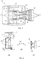
- a ducted fan gas turbine engine generally indicated at 10 has a principal and rotational axis X-X.
- the engine comprises, in axial flow series, an air intake 11, a propulsive fan 12, an intermediate pressure compressor 13, a high-pressure compressor 14, combustion equipment 15, a high-pressure turbine 16, and intermediate pressure turbine 17, a low-pressure turbine 18 and a core engine exhaust nozzle 19.
- a nacelle 21 generally surrounds the engine 10 and defines the intake 11, a bypass duct 22 and a bypass exhaust nozzle 23.
- the gas turbine engine 10 works in a conventional manner so that air entering the intake 11 is accelerated by the fan 12 to produce two air flows: a first air flow A into the intermediate pressure compressor 14 and a second air flow B which passes through the bypass duct 22 to provide propulsive thrust.
- the intermediate pressure compressor 13 compresses the air flow A directed into it before delivering that air to the high pressure compressor 14 where further compression takes place.
- the compressed air exhausted from the high-pressure compressor 14 is directed into the combustion equipment 15 where it is mixed with fuel and the mixture combusted.
- the resultant hot combustion products then expand through, and thereby drive the high, intermediate and low-pressure turbines 16, 17, 18 before being exhausted through the nozzle 19 to provide additional propulsive thrust.
- the high, intermediate and low-pressure turbines respectively drive the high and intermediate pressure compressors 14, 13 and the fan 12 by suitable interconnecting shafts.
- Figure 2(a) shows a closer view of a rotor disc 24 of an intermediate-pressure turbine.
- a row of rotor blades 25 are attached to the rim 26 of the disc.
- a cavity 27 is formed between a front face of the disc and a stationary wall 28 forward of the disc. Cooling air C is introduced to the cavity, and passes through the cavity to exit at one or more locations.
- exit D is to seal the disc rim from ingestion of annulus gas G
- exit E is to ventilate the disc rim blade fixing
- exit F is to feed downstream cavities and seals in the internal air system.
- the rotation of the disc 24 imparts windage power to the air flow passing through the cavity 27. This is potentially detrimental in several respects: (i) it reduces the power which can be transmitted through the turbine shaft to the attached compressor, (ii) it can contribute to the lost power in the overall performance cycle of the engine, and (iii) locally within the cavity it can generate high air temperatures, which in turn may require stronger materials to be specified for the disc or stationary components surrounding the cavity.
- the cooling air C is delivered axially.
- the air is delivered at an inlet angle providing significant swirl in the direction of rotation R of the rotor disc 24 to reduce the windage power loss.
- the nozzles can be formed as angled holes in the stationary wall giving an inlet angle ⁇ which is typically in the range from 60° to 80°.
- Transient blade tip clearances (T) are affected by the disc's rate of thermal response, with higher HTCs speeding up the disc response.
- a speeded up response can in turn affect transient "pinch point" closures, and alter the blade tip clearance rubs generated when running-in the engine.
- the disc front face HTCs may or may not affect the steady-state temperatures of the disc, but even if there is no effect on steady-state temperatures, there can still be an effect on subsequent steady-state running tip clearances resulting from alterations to the running-in rubs.
- the present invention is at least partly based on the recognition that appropriate control of inlet swirl angle can enable windage loss to be reduced and/or blade tip clearances to be improved.
- EP2011968 relates to a secondary flow system that provides a compact injector cooling structure for turbine blades which includes an Angled On-board Injector (AOBI) that locates a metering throat at an inward angle relative to an engine centerline.
- AOBI Angled On-board Injector
- the AOBI positions the metering throat at the inward angle relative to an engine centerline to communicate cooling airflow to an angled annular section of a turbine rotor disk coverplate.
- a first aspect of the present invention provides a gas turbine engine as claimed in claim 1.
- windage power loss is typically a function of the inlet swirl angle.
- the inlet swirl angle e.g. as the engine operating condition changes, the windage power loss can be reduced further.
- the inlet swirl angle can be better optimised to reduce windage power loss.
- the engine may have any one or, to the extent that they are compatible, any combination of the following optional features.
- the air entry nozzles may be circumferentially spaced around the stationary wall.
- the air entry nozzles may be at substantially equal radial positions.
- the cavity feeds cooling air: to seal the rim of the rotor disc against working gas ingestion, and/or to ventilate the fixing for rotor blades attached to the rim of the rotor disc, and/or to feed downstream cavities and seals.
- the inlet swirl angle at a given nozzle can be defined as the angle between the direction of flow of the air delivered out of the exit of the given nozzle, ignoring any radial component to the direction of flow, and a line parallel to the axial direction of the engine at that exit, a positive angle indicating swirl in the direction of rotation of the rotor disc, and a negative angle indicating swirl in the opposite direction of rotation to that of the rotor disc.
- the first inlet swirl angle can then be a positive angle
- the second inlet swirl angle can be a positive angle less than first swirl angle, a zero angle or a negative angle.
- the first inlet swirl angle may be in the range from +45° to +80°.
- the nozzles of the first and second portions may alternate with each other in the circumferential direction around the stationary wall.
- the switching system supplies compressed air only to the nozzles of the first portion or only to the nozzles of the second portion, e.g. by employing a two-position valve to switch the compressed air supply.
- the switching system allows varying proportions of compressed air to be supplied simultaneously to the nozzles of the first and the second portions, e.g. by employing a multi-position or continuously-variable valve to switch the compressed air supply.
- intermediate amounts of swirl can be generated in the cooling air delivered into the cavity. This is particularly useful for optimising the amount swirl for different operating conditions to reduce windage losses, to reduce transient tip clearances and/or to control disc thermal stresses.
- the first and second portions of the nozzles can be at the same radial height.
- the first portion of the nozzles can be at a first radial height and the second portion of the nozzles can be at a different second radial height.
- a greater radial height can be preferable for reducing the windage loss, while a lower radial height can be preferable for increasing HTCs.
- a further option is that some of the nozzles of the first portion are at a first radial height and others of the nozzles of the first portion are at a different second radial height. Likewise, some of the nozzles of the second portion can be at the first radial height and others of the nozzles of the second portion can be at the second radial height.
- a second aspect of the present invention provides a method as claimed in claim 7.
- the method may have any one or, to the extent that they are compatible, any combination of the following optional features.
- the air entry nozzles may be circumferentially spaced around the stationary wall.
- the air entry nozzles may be at substantially equal radial positions.
- the method may further include feeding the delivered air: to seal the rim of the rotor disc against working gas ingestion, and/or to ventilate the fixing for rotor blades attached to the rim of the rotor disc, and/or to feed downstream cavities and seals.
- the first inlet swirl angle can be a positive angle
- the second inlet swirl angle can be a positive angle less than first swirl angle, a zero angle or a negative angle.
- the first inlet swirl angle may be in the range from +45° to +90°.
- the nozzles of the first and second portions may alternate with each other in the circumferential direction around the stationary wall.
- the compressed air may switch between supplying only the nozzles of the first portion and supplying only the nozzles of the second portion.
- varying proportions of compressed air may be supplied simultaneously to the nozzles of the first and the second portions.
- the first portion of the air entry nozzles may be used to reduce windage losses during steady-state engine operation.
- the second portion of the air entry nozzles may be used for tip clearance control during engine thermal transients.
- the first and second portions of the nozzles can be at the same radial height.
- the first portion of the nozzles can be at a first radial height and the second portion of the nozzles can be at a different second radial height.
- a further option is that some of the nozzles of the first portion are at a first radial height and others of the nozzles of the first portion are at a different second radial height.
- some of the nozzles of the second portion can be at the first radial height and others of the nozzles of the second portion can be at the second radial height.
- the stationary wall 28 of the engine of Figure 3 has a first portion of air entry nozzles 29' which each provide a first inlet swirl angle ⁇ 1 , and a second portion of air entry nozzles 29" which each provide a different second inlet swirl angle ⁇ 2 .
- the first and the second nozzles alternate circumferentially around the wall, although other arrangements of nozzles are possible (for example, groups of first and second nozzles may alternate circumferentially around the wall, and there may be different numbers of first and second nozzles).
- the first inlet swirl angle is in the range from +45° to +80°
- the second inlet swirl angle is a positive angle which is less than first swirl angle, a zero angle or a negative angle.
- the engine also has a cooling air supply arrangement 30, which is shown schematically in Figure 4 , and which accepts a flow of compressed air bled from the compressor section of the engine and supplies the compressed air to the air entry nozzles 29', 29" for delivery into the cavity.
- the cooling air supply arrangement accepts compressed air bled from the compressor section of the engine and supplies the compressed air to the nozzles.
- the arrangement comprises a two-position valve 31, and first 32' ductwork and second 32" ductwork which lead from the valve to respectively the first nozzles 29' and the second nozzles 29".
- the valve can be inboard or outboard of the working gas annulus of the engine.
- the first nozzles 29' provide a large swirl angle ⁇ 1 in the direction of rotation R of the disc 24, and are used for windage reduction.
- the second nozzles 29" provide a smaller swirl angle ⁇ 2 in the direction of rotation R, or even a zero or negative swirl and are used for transient tip clearance improvement.
- a typical mode of valve scheduling would be for the first nozzles to be operated during steady-state engine operation and for the second nozzles to be operated for a period of time during engine thermal transient heating and cooling phases. In this way, an optimum swirl angle can be used for windage reduction at certain operating conditions, and, separately, an optimum swirl angle for control of tip clearance T can be used at other conditions.
- first and second nozzles are shown in Figure 3 at the same radial position, an option is for them to be at different radial positions.
- the first nozzles can be at a higher radius if their primary use is for optimising the swirl at the blade feed entry (exit E), and the second nozzles can be at a lower radius, if their primary purpose is to alter the HTCs the air flow generates on the disc front face.
- the individual entry nozzles 29', 29" will usually be of circular cross-section, there is no restriction on their cross-sectional shape. There are also no requirements for the cross-sectional shapes of the first and second nozzles to be the same, and for the total flow areas of the first and second nozzles to be equal.
- valve scheduling could call for the switching to the second nozzles only for selected thermal transients, e.g. for cooling transients only.
- the valve 31 can be of a multi-position or continuously-variable type instead of a two-position valve. In this way, at any point in time, the delivered air into the cavity 27 could be through both the first 29' and the second 29" nozzles. The amount of swirl can thus be optimised for different phases of flight.
- the valve 31 could be of the vortex amplifier type disclosed in US 7712317 .
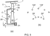
- Figure 5 shows schematically (a) a view on a longitudinal cross-section of a rotor disc 24 of an intermediate-pressure turbine of an engine according to a further embodiment of the present invention, and (b) a view along the axis of the engine of a part of the downstream face of a stationary wall 28 forward of the rotor disc. Similar features in Figures 2 , 3 and 5 share the same reference numbers.
- the stationary wall contains two sets of entry nozzles, a first set 29', 29" at a first radius indicated by the height of the arrow of cooling air C, and a second set 129', 129" at a second radius indicated by the height of the arrow of cooling air C'.
- a first portion of the air entry nozzles 29', 129' (drawn from both sets) provide the first inlet swirl angle ⁇ 1
- a second portion of air entry nozzles 29", 129" (again drawn from both sets) provide the different second inlet swirl angle ⁇ 2 .
- the swirl angle can be determined by switching between the first portion and the second portion of the nozzles.
Claims (8)
- Gasturbinentriebwerk, das in Strömungsreihenfolge einen Verdichterteil, eine Brennkammer und einen Turbinenteil aufweist, wobei das Gasturbinentriebwerk einschließt:eine Turbinenteil-Rotorscheibe (24),eine stationäre Wand (28) vor einer Frontfläche der Rotorscheibe oder rückwärtig einer hinteren Fläche der Rotorscheibe, wobei die stationäre Wand einen Hohlraum (27) zwischen der stationären Wand und der Rotorscheibe definiert, und eine Vielzahl von Lufteintrittsdüsen (29', 29") aufweist, die konfiguriert sind, Kühlluft mit einem Einlass-Verwirbelungswinkel in den Hohlraum zu liefern, undeine Versorgungsanordnung (30) für Kühlluft, die eine Strömung komprimierter Kühlluft akzeptiert, die vom Verdichterteil abgezapft wurde und die komprimierte Kühlluft zu den Lufteintrittsdüsen zur Lieferung in den Hohlraum zuführt;dadurch gekennzeichnet, dass
die Versorgungsanordnung für Kühlluft und die Lufteintrittsdüsen konfiguriert sind, den Einlass-Verwirbelungswinkel der komprimierten Kühlluft, die durch die Düsen in den Hohlraum geliefert wird, zwischen einem ersten Einlass-Verwirbelungswinkel (α1) und einem verschiedenen zweiten Einlass-Verwirbelungswinkel (α2) zu variieren; und
dass ein erster Abschnitt der Lufteintrittsdüsen (29') den ersten Einlass-Verwirbelungswinkel bereitstellt und ein zweiter Abschnitt der Lufteintrittsdüsen (29") den zweiten Einlass-Verwirbelungswinkel bereitstellt, wobei die Versorgungsanordnung für Kühlluft ein Schaltsystem zum Schalten der zugeführten komprimierten Kühlluft zwischen den ersten und zweiten Abschnitten aufweist, um den Einlass-Verwirbelungswinkel zu variieren. - Gasturbinentriebwerk nach Anspruch 1, wobei:der Einlass-Verwirbelungswinkel an einer gegebenen Lufteintrittsdüse als der Winkel zwischen der Strömungsrichtung der aus dem Ausgang der gegebenen Lufteintrittsdüse gelieferten Luft, unter Ignorieren irgendeiner radialen Komponente zur Strömungsrichtung, und einer Linie parallel zur Achsrichtung des Triebwerks am Ausgang definiert ist, wobei ein positiver Winkel Verwirbelung in der Rotationsrichtung der Rotorscheibe anzeigt und ein negativer Winkel Verwirbelung in der entgegengesetzten Rotationsrichtung zu jener der Rotorscheibe anzeigt, wobei der erste Einlass-Verwirbelungswinkel ein positiver Winkel ist undder zweite Einlass-Verwirbelungswinkel ein positiver Winkel weniger als der erste Verwirbelungswinkel, ein Nullwinkel oder ein negativer Winkel ist.
- Gasturbinentriebwerk nach Anspruch 2, wobei der erste Einlass-Verwirbelungswinkel im Bereich von +45° bis +90° liegt.
- Gasturbinentriebwerk nach einem der vorhergehenden Ansprüche,
wobei das Schaltsystem konfiguriert ist, simultan variierende Proportionen komprimierter Kühlluft an die Lufteintrittsdüsen der ersten und der zweiten Abschnitte zu liefern. - Gasturbinentriebwerk nach einem der Ansprüche 1 bis 4,
wobei sich der erste Abschnitt der Lufteintrittsdüsen auf einer ersten radialen Höhe befindet und sich der zweite Abschnitt der Lufteintrittsdüsen auf einer verschiedenen zweiten radialen Höhe befindet. - Gasturbinentriebwerk nach einem der Ansprüche 1 bis 4, wobei:sich einige der Lufteintrittsdüsen des ersten Abschnitts auf einer ersten radialen Höhe befinden und sich andere der Lufteintrittsdüsen des ersten Abschnitts auf einer verschiedenen zweiten radialen Höhe befinden; undsich einige der Lufteintrittsdüsen des zweiten Abschnitts auf einer ersten radialen Höhe befinden und sich andere der Lufteintrittsdüsen des zweiten Abschnitts auf der zweiten radialen Höhe befinden.
- Verfahren zum Betreiben eines Gasturbinentriebwerks, das in Strömungsreihenfolge einen Verdichterteil, eine Brennkammer und einen Turbinenteil aufweist, wobei ein Hohlraum (27) zwischen einer Turbinenteil-Rotorscheibe (24) und einer stationären Wand (28) vor einer Frontfläche der Rotorscheibe oder rückwärtig einer hinteren Fläche der Rotorscheibe definiert ist, wobei die stationäre Wand eine Vielzahl von Lufteintrittsdüsen aufweist, die konfiguriert sind, Kühlluft in den Hohlraum mit einem Einlass-Verwirbelungswinkel zu liefern, wobei ein erster Abschnitt der Lufteintrittsdüsen einen ersten Einlass-Verwirbelungswinkel bereitstellt und ein zweiter Abschnitt der Lufteintrittsdüsen einen verschiedenen zweiten Einlass-Verwirbelungswinkel bereitstellt, wobei das Verfahren einschließt:Zuführen einer Strömung von komprimierter Kühlluft, die vom Verdichteteil abgezapft ist, zu der Vielzahl von Lufteintrittsdüsen an der stationären Wand,Liefern der komprimierten Kühlluft durch die Lufteintrittsdüsen mit einem Einlass-Verwirbelungswinkel in den Hohlraum, undSchalten der Versorgung komprimierter Kühlluft zwischen den ersten und zweiten Abschnitten der Lufteintrittsdüsen, um den Einlass-Verwirbelungswinkel zwischen dem ersten Einlass-Verwirbelungswinkel (α1) und dem zweiten Einlass-Verwirbelungswinkel (α2) zu variieren.
- Verfahren wie in Anspruch 7 beansprucht, wobei das Schalten der Versorgung komprimierter Kühlluft das simultane Liefern variierender Proportionen der komprimierten Kühlluft zu den Lufteintrittsdüsen der ersten und zweiten Abschnitte umfasst.
Applications Claiming Priority (1)
| Application Number | Priority Date | Filing Date | Title |
|---|---|---|---|
| GBGB1103890.8A GB201103890D0 (en) | 2011-03-08 | 2011-03-08 | Gas turbine engine swirled cooling air |
Publications (3)
| Publication Number | Publication Date |
|---|---|
| EP2497904A2 EP2497904A2 (de) | 2012-09-12 |
| EP2497904A3 EP2497904A3 (de) | 2018-03-07 |
| EP2497904B1 true EP2497904B1 (de) | 2019-01-16 |
Family
ID=43923356
Family Applications (1)
| Application Number | Title | Priority Date | Filing Date |
|---|---|---|---|
| EP12156054.4A Active EP2497904B1 (de) | 2011-03-08 | 2012-02-17 | Gasturbinenmotor-Rotorkühlung mit verwirbelter Kühlungsluft |
Country Status (3)
| Country | Link |
|---|---|
| US (1) | US8555654B2 (de) |
| EP (1) | EP2497904B1 (de) |
| GB (1) | GB201103890D0 (de) |
Families Citing this family (5)
| Publication number | Priority date | Publication date | Assignee | Title |
|---|---|---|---|---|
| US9631512B2 (en) | 2013-01-31 | 2017-04-25 | Solar Turbines Incorporated | Gas turbine offline compressor wash with buffer air from combustor |
| US8778091B1 (en) | 2013-01-31 | 2014-07-15 | Solar Turbines Inc. | Compressor wash with air to turbine cooling passages |
| GB201412869D0 (en) | 2014-07-21 | 2014-09-03 | Rolls Royce Plc | Pressure controlled chamber |
| US10030582B2 (en) | 2015-02-09 | 2018-07-24 | United Technologies Corporation | Orientation feature for swirler tube |
| US20170292532A1 (en) * | 2016-04-08 | 2017-10-12 | United Technologies Corporation | Compressor secondary flow aft cone cooling scheme |
Family Cites Families (9)
| Publication number | Priority date | Publication date | Assignee | Title |
|---|---|---|---|---|
| US3043561A (en) * | 1958-12-29 | 1962-07-10 | Gen Electric | Turbine rotor ventilation system |
| US3647313A (en) * | 1970-06-01 | 1972-03-07 | Gen Electric | Gas turbine engines with compressor rotor cooling |
| US3936215A (en) * | 1974-12-20 | 1976-02-03 | United Technologies Corporation | Turbine vane cooling |
| FR2514408B1 (fr) | 1981-10-14 | 1985-11-08 | Snecma | Dispositif pour controler les dilatations et les contraintes thermiques dans un disque de turbine a gaz |
| US4822244A (en) * | 1987-10-15 | 1989-04-18 | United Technologies Corporation | Tobi |
| US5310319A (en) * | 1993-01-12 | 1994-05-10 | United Technologies Corporation | Free standing turbine disk sideplate assembly |
| GB2437969B (en) | 2006-04-13 | 2011-03-23 | Rolls Royce Plc | Flow control systems |
| US8562285B2 (en) * | 2007-07-02 | 2013-10-22 | United Technologies Corporation | Angled on-board injector |
| US8381533B2 (en) * | 2009-04-30 | 2013-02-26 | Honeywell International Inc. | Direct transfer axial tangential onboard injector system (TOBI) with self-supporting seal plate |
-
2011
- 2011-03-08 GB GBGB1103890.8A patent/GB201103890D0/en not_active Ceased
-
2012
- 2012-02-17 US US13/399,424 patent/US8555654B2/en active Active
- 2012-02-17 EP EP12156054.4A patent/EP2497904B1/de active Active
Non-Patent Citations (1)
| Title |
|---|
| None * |
Also Published As
| Publication number | Publication date |
|---|---|
| EP2497904A3 (de) | 2018-03-07 |
| GB201103890D0 (en) | 2011-04-20 |
| EP2497904A2 (de) | 2012-09-12 |
| US20120227414A1 (en) | 2012-09-13 |
| US8555654B2 (en) | 2013-10-15 |
Similar Documents
| Publication | Publication Date | Title |
|---|---|---|
| US11002195B2 (en) | Intercooled cooling air with auxiliary compressor control | |
| US10718268B2 (en) | Intercooled cooling air with dual pass heat exchanger | |
| EP3239478B1 (de) | Kombinierter antrieb für die luft-verdichter der jeweiligen kühlsysteme für kabinenklimatisierung und kühlung des turbinenabschnitts | |
| US9879603B2 (en) | Axial flow machine cooling system | |
| US7765789B2 (en) | Apparatus and method for assembling gas turbine engines | |
| US7631484B2 (en) | High pressure ratio aft fan | |
| CA2520471C (en) | Methods and apparatus for assembling a gas turbine engine | |
| US20160237906A1 (en) | Intercooled cooling air with heat exchanger packaging | |
| US9856793B2 (en) | Intercooled cooling air with improved air flow | |
| US20160305261A1 (en) | High pressure ratio twin spool industrial gas turbine engine with dual flow high spool compressor | |
| US10113486B2 (en) | Method and system for modulated turbine cooling | |
| JP2013506082A (ja) | 2ブロック圧縮機を備えたコンバーチブルファンエンジン | |
| JP2008163945A (ja) | コンバーチブルガスタービンエンジン | |
| EP2497904B1 (de) | Gasturbinenmotor-Rotorkühlung mit verwirbelter Kühlungsluft | |
| US20190323789A1 (en) | Intercooled cooling air | |
| GB2536628A (en) | HPT Integrated interstage seal and cooling air passageways | |
| EP3109435B1 (de) | Zwischengekühlte kühlluft mit wärmetauschergehäuse | |
| EP3492706B1 (de) | Gasturbinentriebwerk mit blattspitzenspielregelung | |
| US20210301665A1 (en) | Method and apparatus for cooling a portion of a counter-rotating turbine engine |
Legal Events
| Date | Code | Title | Description |
|---|---|---|---|
| PUAI | Public reference made under article 153(3) epc to a published international application that has entered the european phase |
Free format text: ORIGINAL CODE: 0009012 |
|
| AK | Designated contracting states |
Kind code of ref document: A2 Designated state(s): AL AT BE BG CH CY CZ DE DK EE ES FI FR GB GR HR HU IE IS IT LI LT LU LV MC MK MT NL NO PL PT RO RS SE SI SK SM TR |
|
| AX | Request for extension of the european patent |
Extension state: BA ME |
|
| RAP1 | Party data changed (applicant data changed or rights of an application transferred) |
Owner name: ROLLS-ROYCE PLC |
|
| PUAL | Search report despatched |
Free format text: ORIGINAL CODE: 0009013 |
|
| AK | Designated contracting states |
Kind code of ref document: A3 Designated state(s): AL AT BE BG CH CY CZ DE DK EE ES FI FR GB GR HR HU IE IS IT LI LT LU LV MC MK MT NL NO PL PT RO RS SE SI SK SM TR |
|
| AX | Request for extension of the european patent |
Extension state: BA ME |
|
| RIC1 | Information provided on ipc code assigned before grant |
Ipc: F01D 5/08 20060101AFI20180126BHEP |
|
| STAA | Information on the status of an ep patent application or granted ep patent |
Free format text: STATUS: REQUEST FOR EXAMINATION WAS MADE |
|
| 17P | Request for examination filed |
Effective date: 20180817 |
|
| RBV | Designated contracting states (corrected) |
Designated state(s): AL AT BE BG CH CY CZ DE DK EE ES FI FR GB GR HR HU IE IS IT LI LT LU LV MC MK MT NL NO PL PT RO RS SE SI SK SM TR |
|
| GRAP | Despatch of communication of intention to grant a patent |
Free format text: ORIGINAL CODE: EPIDOSNIGR1 |
|
| STAA | Information on the status of an ep patent application or granted ep patent |
Free format text: STATUS: GRANT OF PATENT IS INTENDED |
|
| INTG | Intention to grant announced |
Effective date: 20181019 |
|
| GRAS | Grant fee paid |
Free format text: ORIGINAL CODE: EPIDOSNIGR3 |
|
| GRAA | (expected) grant |
Free format text: ORIGINAL CODE: 0009210 |
|
| STAA | Information on the status of an ep patent application or granted ep patent |
Free format text: STATUS: THE PATENT HAS BEEN GRANTED |
|
| AK | Designated contracting states |
Kind code of ref document: B1 Designated state(s): AL AT BE BG CH CY CZ DE DK EE ES FI FR GB GR HR HU IE IS IT LI LT LU LV MC MK MT NL NO PL PT RO RS SE SI SK SM TR |
|
| REG | Reference to a national code |
Ref country code: GB Ref legal event code: FG4D |
|
| REG | Reference to a national code |
Ref country code: CH Ref legal event code: EP |
|
| REG | Reference to a national code |
Ref country code: IE Ref legal event code: FG4D |
|
| REG | Reference to a national code |
Ref country code: DE Ref legal event code: R096 Ref document number: 602012055929 Country of ref document: DE |
|
| REG | Reference to a national code |
Ref country code: AT Ref legal event code: REF Ref document number: 1089834 Country of ref document: AT Kind code of ref document: T Effective date: 20190215 |
|
| REG | Reference to a national code |
Ref country code: NL Ref legal event code: MP Effective date: 20190116 |
|
| REG | Reference to a national code |
Ref country code: LT Ref legal event code: MG4D |
|
| PG25 | Lapsed in a contracting state [announced via postgrant information from national office to epo] |
Ref country code: NL Free format text: LAPSE BECAUSE OF FAILURE TO SUBMIT A TRANSLATION OF THE DESCRIPTION OR TO PAY THE FEE WITHIN THE PRESCRIBED TIME-LIMIT Effective date: 20190116 |
|
| REG | Reference to a national code |
Ref country code: AT Ref legal event code: MK05 Ref document number: 1089834 Country of ref document: AT Kind code of ref document: T Effective date: 20190116 |
|
| PG25 | Lapsed in a contracting state [announced via postgrant information from national office to epo] |
Ref country code: FI Free format text: LAPSE BECAUSE OF FAILURE TO SUBMIT A TRANSLATION OF THE DESCRIPTION OR TO PAY THE FEE WITHIN THE PRESCRIBED TIME-LIMIT Effective date: 20190116 Ref country code: LT Free format text: LAPSE BECAUSE OF FAILURE TO SUBMIT A TRANSLATION OF THE DESCRIPTION OR TO PAY THE FEE WITHIN THE PRESCRIBED TIME-LIMIT Effective date: 20190116 Ref country code: ES Free format text: LAPSE BECAUSE OF FAILURE TO SUBMIT A TRANSLATION OF THE DESCRIPTION OR TO PAY THE FEE WITHIN THE PRESCRIBED TIME-LIMIT Effective date: 20190116 Ref country code: PL Free format text: LAPSE BECAUSE OF FAILURE TO SUBMIT A TRANSLATION OF THE DESCRIPTION OR TO PAY THE FEE WITHIN THE PRESCRIBED TIME-LIMIT Effective date: 20190116 Ref country code: NO Free format text: LAPSE BECAUSE OF FAILURE TO SUBMIT A TRANSLATION OF THE DESCRIPTION OR TO PAY THE FEE WITHIN THE PRESCRIBED TIME-LIMIT Effective date: 20190416 Ref country code: PT Free format text: LAPSE BECAUSE OF FAILURE TO SUBMIT A TRANSLATION OF THE DESCRIPTION OR TO PAY THE FEE WITHIN THE PRESCRIBED TIME-LIMIT Effective date: 20190516 Ref country code: SE Free format text: LAPSE BECAUSE OF FAILURE TO SUBMIT A TRANSLATION OF THE DESCRIPTION OR TO PAY THE FEE WITHIN THE PRESCRIBED TIME-LIMIT Effective date: 20190116 |
|
| PG25 | Lapsed in a contracting state [announced via postgrant information from national office to epo] |
Ref country code: LV Free format text: LAPSE BECAUSE OF FAILURE TO SUBMIT A TRANSLATION OF THE DESCRIPTION OR TO PAY THE FEE WITHIN THE PRESCRIBED TIME-LIMIT Effective date: 20190116 Ref country code: RS Free format text: LAPSE BECAUSE OF FAILURE TO SUBMIT A TRANSLATION OF THE DESCRIPTION OR TO PAY THE FEE WITHIN THE PRESCRIBED TIME-LIMIT Effective date: 20190116 Ref country code: HR Free format text: LAPSE BECAUSE OF FAILURE TO SUBMIT A TRANSLATION OF THE DESCRIPTION OR TO PAY THE FEE WITHIN THE PRESCRIBED TIME-LIMIT Effective date: 20190116 Ref country code: GR Free format text: LAPSE BECAUSE OF FAILURE TO SUBMIT A TRANSLATION OF THE DESCRIPTION OR TO PAY THE FEE WITHIN THE PRESCRIBED TIME-LIMIT Effective date: 20190417 Ref country code: IS Free format text: LAPSE BECAUSE OF FAILURE TO SUBMIT A TRANSLATION OF THE DESCRIPTION OR TO PAY THE FEE WITHIN THE PRESCRIBED TIME-LIMIT Effective date: 20190516 Ref country code: BG Free format text: LAPSE BECAUSE OF FAILURE TO SUBMIT A TRANSLATION OF THE DESCRIPTION OR TO PAY THE FEE WITHIN THE PRESCRIBED TIME-LIMIT Effective date: 20190416 |
|
| REG | Reference to a national code |
Ref country code: CH Ref legal event code: PL |
|
| REG | Reference to a national code |
Ref country code: DE Ref legal event code: R097 Ref document number: 602012055929 Country of ref document: DE |
|
| PG25 | Lapsed in a contracting state [announced via postgrant information from national office to epo] |
Ref country code: EE Free format text: LAPSE BECAUSE OF FAILURE TO SUBMIT A TRANSLATION OF THE DESCRIPTION OR TO PAY THE FEE WITHIN THE PRESCRIBED TIME-LIMIT Effective date: 20190116 Ref country code: MC Free format text: LAPSE BECAUSE OF FAILURE TO SUBMIT A TRANSLATION OF THE DESCRIPTION OR TO PAY THE FEE WITHIN THE PRESCRIBED TIME-LIMIT Effective date: 20190116 Ref country code: LU Free format text: LAPSE BECAUSE OF NON-PAYMENT OF DUE FEES Effective date: 20190217 Ref country code: CZ Free format text: LAPSE BECAUSE OF FAILURE TO SUBMIT A TRANSLATION OF THE DESCRIPTION OR TO PAY THE FEE WITHIN THE PRESCRIBED TIME-LIMIT Effective date: 20190116 Ref country code: RO Free format text: LAPSE BECAUSE OF FAILURE TO SUBMIT A TRANSLATION OF THE DESCRIPTION OR TO PAY THE FEE WITHIN THE PRESCRIBED TIME-LIMIT Effective date: 20190116 Ref country code: SK Free format text: LAPSE BECAUSE OF FAILURE TO SUBMIT A TRANSLATION OF THE DESCRIPTION OR TO PAY THE FEE WITHIN THE PRESCRIBED TIME-LIMIT Effective date: 20190116 Ref country code: AL Free format text: LAPSE BECAUSE OF FAILURE TO SUBMIT A TRANSLATION OF THE DESCRIPTION OR TO PAY THE FEE WITHIN THE PRESCRIBED TIME-LIMIT Effective date: 20190116 Ref country code: IT Free format text: LAPSE BECAUSE OF FAILURE TO SUBMIT A TRANSLATION OF THE DESCRIPTION OR TO PAY THE FEE WITHIN THE PRESCRIBED TIME-LIMIT Effective date: 20190116 Ref country code: AT Free format text: LAPSE BECAUSE OF FAILURE TO SUBMIT A TRANSLATION OF THE DESCRIPTION OR TO PAY THE FEE WITHIN THE PRESCRIBED TIME-LIMIT Effective date: 20190116 Ref country code: DK Free format text: LAPSE BECAUSE OF FAILURE TO SUBMIT A TRANSLATION OF THE DESCRIPTION OR TO PAY THE FEE WITHIN THE PRESCRIBED TIME-LIMIT Effective date: 20190116 |
|
| REG | Reference to a national code |
Ref country code: BE Ref legal event code: MM Effective date: 20190228 |
|
| PLBE | No opposition filed within time limit |
Free format text: ORIGINAL CODE: 0009261 |
|
| STAA | Information on the status of an ep patent application or granted ep patent |
Free format text: STATUS: NO OPPOSITION FILED WITHIN TIME LIMIT |
|
| REG | Reference to a national code |
Ref country code: IE Ref legal event code: MM4A |
|
| PG25 | Lapsed in a contracting state [announced via postgrant information from national office to epo] |
Ref country code: SM Free format text: LAPSE BECAUSE OF FAILURE TO SUBMIT A TRANSLATION OF THE DESCRIPTION OR TO PAY THE FEE WITHIN THE PRESCRIBED TIME-LIMIT Effective date: 20190116 |
|
| 26N | No opposition filed |
Effective date: 20191017 |
|
| PG25 | Lapsed in a contracting state [announced via postgrant information from national office to epo] |
Ref country code: LI Free format text: LAPSE BECAUSE OF NON-PAYMENT OF DUE FEES Effective date: 20190228 Ref country code: CH Free format text: LAPSE BECAUSE OF NON-PAYMENT OF DUE FEES Effective date: 20190228 |
|
| PG25 | Lapsed in a contracting state [announced via postgrant information from national office to epo] |
Ref country code: IE Free format text: LAPSE BECAUSE OF NON-PAYMENT OF DUE FEES Effective date: 20190217 |
|
| PG25 | Lapsed in a contracting state [announced via postgrant information from national office to epo] |
Ref country code: BE Free format text: LAPSE BECAUSE OF NON-PAYMENT OF DUE FEES Effective date: 20190228 Ref country code: SI Free format text: LAPSE BECAUSE OF FAILURE TO SUBMIT A TRANSLATION OF THE DESCRIPTION OR TO PAY THE FEE WITHIN THE PRESCRIBED TIME-LIMIT Effective date: 20190116 |
|
| PG25 | Lapsed in a contracting state [announced via postgrant information from national office to epo] |
Ref country code: TR Free format text: LAPSE BECAUSE OF FAILURE TO SUBMIT A TRANSLATION OF THE DESCRIPTION OR TO PAY THE FEE WITHIN THE PRESCRIBED TIME-LIMIT Effective date: 20190116 |
|
| PG25 | Lapsed in a contracting state [announced via postgrant information from national office to epo] |
Ref country code: MT Free format text: LAPSE BECAUSE OF NON-PAYMENT OF DUE FEES Effective date: 20190217 |
|
| PG25 | Lapsed in a contracting state [announced via postgrant information from national office to epo] |
Ref country code: CY Free format text: LAPSE BECAUSE OF FAILURE TO SUBMIT A TRANSLATION OF THE DESCRIPTION OR TO PAY THE FEE WITHIN THE PRESCRIBED TIME-LIMIT Effective date: 20190116 |
|
| PG25 | Lapsed in a contracting state [announced via postgrant information from national office to epo] |
Ref country code: HU Free format text: LAPSE BECAUSE OF FAILURE TO SUBMIT A TRANSLATION OF THE DESCRIPTION OR TO PAY THE FEE WITHIN THE PRESCRIBED TIME-LIMIT; INVALID AB INITIO Effective date: 20120217 |
|
| PG25 | Lapsed in a contracting state [announced via postgrant information from national office to epo] |
Ref country code: MK Free format text: LAPSE BECAUSE OF FAILURE TO SUBMIT A TRANSLATION OF THE DESCRIPTION OR TO PAY THE FEE WITHIN THE PRESCRIBED TIME-LIMIT Effective date: 20190116 |
|
| PGFP | Annual fee paid to national office [announced via postgrant information from national office to epo] |
Ref country code: FR Payment date: 20230223 Year of fee payment: 12 |
|
| PGFP | Annual fee paid to national office [announced via postgrant information from national office to epo] |
Ref country code: GB Payment date: 20230214 Year of fee payment: 12 Ref country code: DE Payment date: 20230227 Year of fee payment: 12 |
|
| P01 | Opt-out of the competence of the unified patent court (upc) registered |
Effective date: 20230528 |