EP2497900B1 - Modeling hydraulic fractures - Google Patents
Modeling hydraulic fractures Download PDFInfo
- Publication number
- EP2497900B1 EP2497900B1 EP11250920.3A EP11250920A EP2497900B1 EP 2497900 B1 EP2497900 B1 EP 2497900B1 EP 11250920 A EP11250920 A EP 11250920A EP 2497900 B1 EP2497900 B1 EP 2497900B1
- Authority
- EP
- European Patent Office
- Prior art keywords
- reservoir
- model
- hydraulic fractures
- properties
- well
- Prior art date
- Legal status (The legal status is an assumption and is not a legal conclusion. Google has not performed a legal analysis and makes no representation as to the accuracy of the status listed.)
- Active
Links
- 238000000034 method Methods 0.000 claims description 57
- 230000035699 permeability Effects 0.000 claims description 25
- 239000011148 porous material Substances 0.000 claims description 22
- 238000004519 manufacturing process Methods 0.000 claims description 21
- 230000005484 gravity Effects 0.000 claims description 3
- 239000011435 rock Substances 0.000 claims description 3
- 238000013507 mapping Methods 0.000 claims 1
- 238000005553 drilling Methods 0.000 description 30
- 230000015572 biosynthetic process Effects 0.000 description 29
- 238000005755 formation reaction Methods 0.000 description 29
- 238000004883 computer application Methods 0.000 description 26
- 238000005516 engineering process Methods 0.000 description 22
- 239000012530 fluid Substances 0.000 description 20
- 238000005259 measurement Methods 0.000 description 14
- 238000004891 communication Methods 0.000 description 11
- 238000012545 processing Methods 0.000 description 10
- 230000003287 optical effect Effects 0.000 description 8
- 230000003068 static effect Effects 0.000 description 8
- 238000010586 diagram Methods 0.000 description 4
- 239000000203 mixture Substances 0.000 description 4
- 230000008569 process Effects 0.000 description 4
- 238000004088 simulation Methods 0.000 description 4
- XLYOFNOQVPJJNP-UHFFFAOYSA-N water Substances O XLYOFNOQVPJJNP-UHFFFAOYSA-N 0.000 description 4
- 238000004458 analytical method Methods 0.000 description 3
- 238000013461 design Methods 0.000 description 3
- 230000003993 interaction Effects 0.000 description 3
- 230000002093 peripheral effect Effects 0.000 description 3
- 230000000638 stimulation Effects 0.000 description 3
- 241000191291 Abies alba Species 0.000 description 2
- BVKZGUZCCUSVTD-UHFFFAOYSA-L Carbonate Chemical compound [O-]C([O-])=O BVKZGUZCCUSVTD-UHFFFAOYSA-L 0.000 description 2
- 230000008901 benefit Effects 0.000 description 2
- 238000004364 calculation method Methods 0.000 description 2
- 230000007423 decrease Effects 0.000 description 2
- 230000000694 effects Effects 0.000 description 2
- 230000006870 function Effects 0.000 description 2
- 229930195733 hydrocarbon Natural products 0.000 description 2
- 150000002430 hydrocarbons Chemical class 0.000 description 2
- 230000007246 mechanism Effects 0.000 description 2
- 230000006855 networking Effects 0.000 description 2
- 230000004044 response Effects 0.000 description 2
- 239000004576 sand Substances 0.000 description 2
- 238000012360 testing method Methods 0.000 description 2
- XQCFHQBGMWUEMY-ZPUQHVIOSA-N Nitrovin Chemical compound C=1C=C([N+]([O-])=O)OC=1\C=C\C(=NNC(=N)N)\C=C\C1=CC=C([N+]([O-])=O)O1 XQCFHQBGMWUEMY-ZPUQHVIOSA-N 0.000 description 1
- 230000008859 change Effects 0.000 description 1
- 239000004927 clay Substances 0.000 description 1
- 238000013480 data collection Methods 0.000 description 1
- 239000002360 explosive Substances 0.000 description 1
- 238000001914 filtration Methods 0.000 description 1
- 230000008676 import Effects 0.000 description 1
- 238000002347 injection Methods 0.000 description 1
- 239000007924 injection Substances 0.000 description 1
- 230000005055 memory storage Effects 0.000 description 1
- 238000012544 monitoring process Methods 0.000 description 1
- 230000000704 physical effect Effects 0.000 description 1
- 238000005086 pumping Methods 0.000 description 1
- 230000002285 radioactive effect Effects 0.000 description 1
- 238000011084 recovery Methods 0.000 description 1
- 230000009467 reduction Effects 0.000 description 1
- 238000011160 research Methods 0.000 description 1
- 239000007787 solid Substances 0.000 description 1
- 238000012546 transfer Methods 0.000 description 1
- 230000007723 transport mechanism Effects 0.000 description 1
- 238000011282 treatment Methods 0.000 description 1
- 238000012795 verification Methods 0.000 description 1
Images


Classifications
-
- G—PHYSICS
- G06—COMPUTING; CALCULATING OR COUNTING
- G06F—ELECTRIC DIGITAL DATA PROCESSING
- G06F30/00—Computer-aided design [CAD]
- G06F30/20—Design optimisation, verification or simulation
- G06F30/28—Design optimisation, verification or simulation using fluid dynamics, e.g. using Navier-Stokes equations or computational fluid dynamics [CFD]
-
- G01V20/00—
-
- E—FIXED CONSTRUCTIONS
- E21—EARTH DRILLING; MINING
- E21B—EARTH DRILLING, e.g. DEEP DRILLING; OBTAINING OIL, GAS, WATER, SOLUBLE OR MELTABLE MATERIALS OR A SLURRY OF MINERALS FROM WELLS
- E21B43/00—Methods or apparatus for obtaining oil, gas, water, soluble or meltable materials or a slurry of minerals from wells
- E21B43/25—Methods for stimulating production
- E21B43/26—Methods for stimulating production by forming crevices or fractures
Definitions
- Implementations of various technologies described herein generally relate to geomechanical and petrophysical data processing.
- Hydraulic fracturing generally includes the process of pumping fracturing fluid into a wellbore with hydraulic pumps to create enough downhole pressure to crack or fracture a formation in the subsurface of the earth.
- the fracturing allows proppants to be injected into the formation, thereby creating a plane of high-permeability sand through which fluids, such as hydrocarbons, can flow.
- the proppants remain in place, prop open the fracture and enhance the flow of the fluids into the wellbore.
- hydraulic fracture simulations are used to determine permeability properties of the reservoir or the wellbore.
- these hydraulic fracturing simulators are still limited in that they fail to effectively account for variations in geomechanical and petrophysical properties of the earth.
- Described herein are implementations of various techniques for modeling hydraulic fractures of a well.
- the invention further relates to a computer system and a computer readable medium operable to implement 15 the method.
- a method for modeling hydraulic fractures of a well is performed by a computer application.
- the computer application receives a reservoir model and geomechanical properties of the reservoir.
- the computer application then builds a geomechanical model of the reservoir based on the received reservoir model and the geomechanical properties of the reservoir.
- the computer application uses the geomechanical model of the reservoir to simulate hydraulic fractures of a well.
- the simulated hydraulic fractures indicate the fracture geometry and the permeability profile along a planar fracture in the well.
- the computer application maps the simulated hydraulic fractures onto the reservoir model in order to generate a 3D representation of the hydraulic fractures of a stimulated well.
- the 3D representation of the hydraulic fractures may then be used to update the permeability properties of the reservoir model and to determine production forecasts for the well based on the updated permeability properties.
- the computer application may model the hydraulic fracture-reservoir interaction, evaluate hydraulic fracture containment and conductivity of a well, evaluate the influence of stress changes on hydraulic fracture geometry and investigate the complex interaction between pre-existing geological features and hydraulically induced fractures.
- Figures 1.1-1.4 illustrate simplified, schematic views of oilfield 100 having subterranean formation 102 containing reservoir 104 therein in accordance with implementations of various technologies and techniques described herein.
- Figure 1.1 illustrates a survey operation being performed by a survey tool, such as seismic truck 106.1, to measure properties of the subterranean formation.
- the survey operation is a seismic survey operation for producing sound vibrations.
- one such sound vibration e.g., sound vibration 112 generated by source 110
- sensors such as geophone-receivers 118, situated on the earth's surface.
- the data received 120 is provided as input data to a computer 122.1 of a seismic truck 106.1, and responsive to the input data, computer 122.1 generates seismic data output 124.
- This seismic data output may be stored, transmitted or further processed as desired, for example, by data reduction.
- Figure 1.2 illustrates a drilling operation being performed by drilling tools 106.2 suspended by rig 128 and advanced into subterranean formations 102 to form wellbore 136.
- Mud pit 130 is used to draw drilling mud into the drilling tools via flow line 132 for circulating drilling mud down through the drilling tools, then up wellbore 136 and back to the surface.
- the drilling mud is usually filtered and returned to the mud pit.
- a circulating system may be used for storing, controlling, or filtering the flowing drilling mud.
- the drilling tools are advanced into subterranean formations 102 to reach reservoir 104. Each well may target one or more reservoirs.
- the drilling tools are adapted for measuring downhole properties using logging while drilling tools.
- the logging while drilling tools may also be adapted for taking core sample 133 as shown.
- Computer facilities may be positioned at various locations about the oilfield 100 (e.g., the surface unit 134) and/or at remote locations.
- Surface unit 134 may be used to communicate with the drilling tools and/or offsite operations, as well as with other surface or downhole sensors.
- Surface unit 134 is capable of communicating with the drilling tools to send commands to the drilling tools, and to receive data therefrom.
- Surface unit 134 may also collect data generated during the drilling operation and produce data output 135, which may then be stored or transmitted.
- Sensors (S), such as gauges, may be positioned about oilfield 100 to collect data relating to various oilfield operations as described previously. As shown, sensor (S) is positioned in one or more locations in the drilling tools and/or at rig 128 to measure drilling parameters, such as weight on bit, torque on bit, pressures, temperatures, flow rates, compositions, rotary speed, and/or other parameters of the field operation. Sensors (S) may also be positioned in one or more locations in the circulating system.
- Drilling tools 106.2 may include a bottom hole assembly (BHA) (not shown), generally referenced, near the drill bit (e.g., within several drill collar lengths from the drill bit).
- BHA bottom hole assembly
- the bottom hole assembly includes capabilities for measuring, processing, and storing information, as well as communicating with surface unit 134.
- the bottom hole assembly further includes drill collars for performing various other measurement functions.
- the bottom hole assembly may include a communication subassembly that communicates with surface unit 134.
- the communication subassembly is adapted to send signals to and receive signals from the surface using a communications channel such as mud pulse telemetry, electro-magnetic telemetry, or wired drill pipe communications.
- the communication subassembly may include, for example, a transmitter that generates a signal, such as an acoustic or electromagnetic signal, which is representative of the measured drilling parameters. It will be appreciated by one of skill in the art that a variety of telemetry systems may be employed, such as wired drill pipe, electromagnetic or other known telemetry systems.
- the wellbore is drilled according to a drilling plan that is established prior to drilling.
- the drilling plan typically sets forth equipment, pressures, trajectories and/or other parameters that define the drilling process for the wellsite.
- the drilling operation may then be performed according to the drilling plan. However, as information is gathered, the drilling operation may need to deviate from the drilling plan. Additionally, as drilling or other operations are performed, the subsurface conditions may change.
- the earth model may also need adjustment as new information is collected
- the data gathered by sensors (S) may be collected by surface unit 134 and/or other data collection sources for analysis or other processing.
- the data collected by sensors (S) may be used alone or in combination with other data.
- the data may be collected in one or more databases and/or transmitted on or offsite.
- the data may be historical data, real time data, or combinations thereof.
- the real time data may be used in real time, or stored for later use.
- the data may also be combined with historical data or other inputs for further analysis.
- the data may be stored in separate databases, or combined into a single database.
- Surface unit 134 may include transceiver 137 to allow communications between surface unit 134 and various portions of the oilfield 100 or other locations.
- Surface unit 134 may also be provided with or functionally connected to one or more controllers (not shown) for actuating mechanisms at oilfield 100.
- Surface unit 134 may then send command signals to oilfield 100 in response to data received.
- Surface unit 134 may receive commands via transceiver 137 or may itself execute commands to the controller.
- a processor may be provided to analyze the data (locally or remotely), make the decisions and/or actuate the controller. In this manner, oilfield 100 may be selectively adjusted based on the data collected. This technique may be used to optimize portions of the field operation, such as controlling drilling, weight on bit, pump rates, or other parameters. These adjustments may be made automatically based on computer protocol, and/or manually by an operator. In some cases, well plans may be adjusted to select optimum operating conditions, or to avoid problems.
- Figure 1.3 illustrates a wireline operation being performed by wireline tool 106.3 suspended by rig 128 and into wellbore 136 of Figure 1.2 .
- Wireline tool 106.3 is adapted for deployment into wellbore 136 for generating well logs, performing downhole tests and/or collecting samples.
- Wireline tool 106.3 may be used to provide another method and apparatus for performing a seismic survey operation.
- Wireline tool 106.3 may, for example, have an explosive, radioactive, electrical, or acoustic energy source 144 that sends and/or receives electrical signals to surrounding subterranean formations 102 and fluids therein.
- Wireline tool 106.3 may be operatively connected to, for example, geophones 118 and a computer 122.1 of a seismic truck 106.1 of Figure 1.1 .
- Wireline tool 106.3 may also provide data to surface unit 134.
- Surface unit 134 may collect data generated during the wireline operation and may produce data output 135 that may be stored or transmitted.
- Wireline tool 106.3 may be positioned at various depths in the wellbore 136 to provide a survey or other information relating to the subterranean formation 102.
- Sensors such as gauges, may be positioned about oilfield 100 to collect data relating to various field operations as described previously. As shown, sensor S is positioned in wireline tool 106.3 to measure downhole parameters which relate to, for example porosity, permeability, fluid composition and/or other parameters of the field operation.
- Figure 1.4 illustrates a production operation being performed by production tool 106.4 deployed from a production unit or Christmas tree 129 and into completed wellbore 136 for drawing fluid from the downhole reservoirs into surface facilities 142.
- the fluid flows from reservoir 104 through perforations in the casing (not shown) and into production tool 106.4 in wellbore 136 and to surface facilities 142 via gathering network 146.
- Sensors such as gauges, may be positioned about oilfield 100 to collect data relating to various field operations as described previously. As shown, the sensor (S) may be positioned in production tool 106.4 or associated equipment, such as Christmas tree 129, gathering network 146, surface facility 142, and/or the production facility, to measure fluid parameters, such as fluid composition, flow rates, pressures, temperatures, and/or other parameters of the production operation.
- production tool 106.4 or associated equipment, such as Christmas tree 129, gathering network 146, surface facility 142, and/or the production facility, to measure fluid parameters, such as fluid composition, flow rates, pressures, temperatures, and/or other parameters of the production operation.
- Production may also include injection wells for added recovery.
- One or more gathering facilities may be operatively connected to one or more of the wellsites for selectively collecting downhole fluids from the wellsite(s).
- Figures 1.2-1.4 illustrate tools used to measure properties of an oilfield
- the tools may be used in connection with non-oilfield operations, such as gas fields, mines, aquifers, storage, or other subterranean facilities.
- non-oilfield operations such as gas fields, mines, aquifers, storage, or other subterranean facilities.
- various measurement tools capable of sensing parameters, such as seismic two-way travel time, density, resistivity, production rate, etc., of the subterranean formation and/or its geological formations may be used.
- Various sensors (S) may be located at various positions along the wellbore and/or the monitoring tools to collect and/or monitor the desired data. Other sources of data may also be provided from offsite locations.
- Figures 1.1-1.4 are intended to provide a brief description of an example of a field usable with oilfield application frameworks.
- Part, or all, of oilfield 100 may be on land, water, and/or sea.
- oilfield applications may be utilized with any combination of one or more oilfields, one or more processing facilities and one or more wellsites.
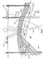
- Figure 2 illustrates a schematic view, partially in cross section of oilfield 200 having data acquisition tools 202.1, 202.2, 202.3 and 202.4 positioned at various locations along oilfield 200 for collecting data of subterranean formation 204 in accordance with implementations of various technologies and techniques described herein.
- Data acquisition tools 202.1-202.4 may be the same as data acquisition tools 106.1-106.4 of Figures 1.1-1.4 , respectively, or others not depicted.
- data acquisition tools 202.1-202.4 generate data plots or measurements 208.1-208.4, respectively. These data plots are depicted along oilfield 200 to demonstrate the data generated by the various operations.
- Data plots 208.1-208.3 are examples of static data plots that may be generated by data acquisition tools 202.1-202.3, respectively; however, it should be understood that data plots 208.1-208.3 may also be data plots that are updated in real time. These measurements may be analyzed to better define the properties of the formation(s) and/or determine the accuracy of the measurements and/or for checking for errors. The plots of each of the respective measurements may be aligned and scaled for comparison and verification of the properties.
- Static data plot 208.1 is a seismic two-way response over a period of time.
- Static plot 208.2 is core sample data measured from a core sample of the formation 204.
- the core sample may be used to provide data, such as a graph of the density, porosity, permeability, or some other physical property of the core sample over the length of the core. Tests for density and viscosity may be performed on the fluids in the core at varying pressures and temperatures.
- Static data plot 208.3 is a logging trace that typically provides a resistivity or other measurement of the formation at various depths.
- a production decline curve or graph 208.4 is a dynamic data plot of the fluid flow rate over time.
- the production decline curve typically provides the production rate as a function of time.
- measurements are taken of fluid properties, such as flow rates, pressures, composition, etc.
- Other data may also be collected, such as historical data, user inputs, economic information, and/or other measurement data and other parameters of interest.
- the static and dynamic measurements may be analyzed and used to generate models of the subterranean formation to determine characteristics thereof. Similar measurements may also be used to measure changes in formation aspects over time.
- the subterranean structure 204 has a plurality of geological formations 206.1-206.4. As shown, this structure has several formations or layers, including a shale layer 206.1, a carbonate layer 206.2, a shale layer 206.3 and a sand layer 206.4. A fault 207 extends through the shale layer 206.1 and the carbonate layer 206.2.
- the static data acquisition tools are adapted to take measurements and detect characteristics of the formations.
- oilfield 200 may contain a variety of geological structures and/or formations, sometimes having extreme complexity. In some locations, typically below the water line, fluid may occupy pore spaces of the formations.
- Each of the measurement devices may be used to measure properties of the formations and/or its geological features. While each acquisition tool is shown as being in specific locations in oilfield 200, it will be appreciated that one or more types of measurement may be taken at one or more locations across one or more fields or other locations for comparison and/or analysis.
- seismic data displayed in static data plot 208.1 from data acquisition tool 202.1 is used by a geophysicist to determine characteristics of the subterranean formations and features.
- the core data shown in static plot 208.2 and/or log data from well log 208.3 are typically used by a geologist to determine various characteristics of the subterranean formation.
- the production data from graph 208.4 is typically used by the reservoir engineer to determine fluid flow reservoir characteristics.
- the data analyzed by the geologist, geophysicist and the reservoir engineer may be analyzed using modeling techniques.
- Figure 3 illustrates an oilfield 300 for performing production operations in accordance with implementations of various technologies and techniques described herein.
- the oilfield has a plurality of wellsites 302 operatively connected to central processing facility 354.
- the oilfield configuration of Figure 3 is not intended to limit the scope of the oilfield application system. Part or all of the oilfield may be on land and/or sea. Also, while a single oilfield with a single processing facility and a plurality of wellsites is depicted, any combination of one or more oilfields, one or more processing facilities and one or more wellsites may be present.
- Each wellsite 302 has equipment that forms wellbore 336 into the earth.
- the wellbores extend through subterranean formations 306 including reservoirs 304.
- These reservoirs 304 contain fluids, such as hydrocarbons.
- the wellsites draw fluid from the reservoirs and pass them to the processing facilities via surface networks 344.
- the surface networks 344 have tubing and control mechanisms for controlling the flow of fluids from the wellsite to processing facility 354.
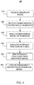
- Figure 4 illustrates a flow diagram of a method for modeling hydraulic fractures in a well in accordance with implementations of various technologies and techniques described herein.
- method 400 is performed by a computer application. It should be understood that while method 400 indicates a particular order of execution of the operations, in some implementations, certain portions of the operations might be executed in a different order. The following description of method 400 is provided with reference to data flow diagram 500 of Figures 5A-5B .
- Reservoir model 505 may describe the flow of fluids in the reservoir.
- Reservoir model 505 indicates various petrophysical properties of the subsurface of the earth near the reservoir.
- the petrophysical properties 530 may include pore pressure properties 510 in the subsurface of the earth and permeability properties along the trajectory of a well in the reservoir.
- Pore pressure properties 510 may include pore pressure changes along a well in the reservoir.
- the computer application receives mechanical properties 515 of the reservoir.
- Mechanical properties 515 describe mechanical properties of the subsurface of the earth.
- mechanical properties 515 may include faults, fractures and mechanical properties of the rock mass in which the reservoir resides.
- the computer application builds a geomechanical model of the reservoir based on reservoir model 505 and mechanical properties 515.
- the geomechanical model may incorporate pore pressure properties 510 such as pore pressure changes together with mechanical properties 515.
- Pore pressure properties 510 may include pore pressure loading.
- gravity loading and tectonics loading may be used to calculate a 3D stress state over the geomechanical model of the reservoir.
- the computer application may use pore pressure loading, gravity loading and tectonics loading elements to globally solve a set of three dimensional equilibrium equations. As a result, the computer application may account for the effects of faults/fractures in the calculation of the stresses, the lateral contrasts between mechanical properties 515 and the interaction between the earth layers.
- pore pressure changes in reservoir model 505 may be used to calculate corresponding stress fields in the geomechanical model of the reservoir.
- the geomechanical model of the reservoir may include stress fields near the well, elastic mechanical properties of the earth near the well, pore pressure properties along the trajectory of the well, the porosity and impact flow permeability properties along the trajectory of the well and the saturation properties (water, gas and oil saturations) of the subsurface of the earth near the well.
- the geomechanical model of the reservoir may be represented as a three dimensional model or map of the stress tensors or principal stresses of the subsurface of the earth (e.g., stresses 520).
- the computer application may import the geomechanical model into a seismic-to-simulation software to generate petrophysical and geomechanical parameter logs.
- the petrophysical and geomechanical logs may include stress contrast zones that may be used to more efficiently simulate hydraulic fractures in a simulator.
- the computer application simulates a hydraulic fracture of the well based on the geomechanical model of the reservoir and the reservoir model.
- inputs for the simulation of the hydraulic fracture includes stresses 520, namely the 3D stress map from the geomechanical model of the reservoir, and optionally mechanical properties 525 from the geomechanical model of the reservoir, pore pressure properties 510 from reservoir model 505, and petrophysical properties 530 from reservoir model 505.
- Petrophysical properties 530 may include properties of the reservoir such as clay volume, total porosity, effective porosity, water saturation, permeability and the like.
- Simulated hydraulic fracture 535 may indicate the fracture geometry such as variations in height, width and length of the fracture. Additionally, simulated hydraulic fracture 535 may also indicate the permeability profile along a one-dimensional or two-dimensional planar fracture.
- the computer application may be able to enhance the understanding of the effects of the stress state on hydraulic fracture stimulations, thereby simulating more accurate hydraulic fracture paths or propagation directions.
- the computer application maps simulated hydraulic fractures 535 onto reservoir model 505 using stresses 520 to generate a three dimensional representation of the hydraulic fracture 540 for a stimulated well.
- the computer application may generate the three dimensional representation of the hydraulic fracture 540 by building a three dimensional volume of the hydraulic fracture using the geometry information as indicated in simulated hydraulic fractures 535.
- the computer application may build the three dimensional volume starting from the well location for each grid cell in reservoir model 505 on a cell-by-cell basis using the stress directions, as indicated in stresses 520, as a guide to determine the hydraulic fracture path.
- simulated hydraulic fractures 535 may be planar features, by using a three dimensional stress field as indicated in stresses 520 as a guide, the computer application generates non-symmetrical hydraulic fracture propagations away from the well in order to build the three dimensional volume of the hydraulic fracture.
- the computer application may use the three dimensional representation of the hydraulic fracture 540 to create a hydraulic fracture design for the reservoir. Data regarding the hydraulic fractures in the wellbore may then be gathered and used to recalibrate simulated hydraulic fractures 535.
- the recalibration process may be used to reduce uncertainties in mechanical properties 525, petrophysical properties 530 and simulated hydraulic fractures 535.
- the recalibration process may be repeated until the discrepancy between a first set of recalibrated data and a subsequent set of recalibrated data is less than a predetermined value.
- the computer application may update the permeability properties of each grid cell in the reservoir model that has been intersected by the three dimensional representation of the hydraulic fracture 540.
- the computer application may use the permeability properties 545 from reservoir model 505 as the initial permeability properties in the reservoir model.
- the computer application may update the initial permeability properties 545 of reservoir model 505 based on the three dimensional representation of the hydraulic fracture 540.
- the permeability update may be done using tracking software that ensures that the hydraulic fracture direction on a cell-by-cell basis in the reservoir model 505 follows the direction of the maximum principal horizontal stress.
- the computer application may then use the updated permeability properties to generate an updated reservoir model 550 having the updated permeability properties.
- the computer application may determine production forecasts for the stimulated well based on the updated permeability properties.
- method 400 has been described as being used to determine updated permeability properties and production forecasts, it should be noted that method 400 is not limited to being used for these tasks. For instance, method 400 may also be used to determine an optimum stimulation design, thus allowing for an enhanced prediction of reservoir performance, and enhanced predictions of projected revenue.
- Method 400 creates a 3D representation of the hydraulic fractures.
- traditional methods for simulating hydraulic fractures use the principal stresses in the pay zone, such as a minimum principal horizontal stress, as an input in its simulator.
- the minimum principal horizontal stress may be calculated using a one-dimensional mechanical earth model (MEM).
- MEM mechanical earth model
- the traditional method for simulating hydraulic fractures use a one dimensional mechanical earth model for doing rock mechanics calculations and simulations.
- the benefits of the three dimensional representation become apparent when opening up new areas of predictive modeling such as the prediction of changes in stress magnitudes and directions caused by production. As a result, the predicted stress magnitudes and directions can be used to guide the design of better stimulation treatments.
- FIG. 6 illustrates a computer system 600 into which implementations of various technologies and techniques described herein may be implemented.
- computing system 600 may be a conventional desktop or a server computer, but it should be noted that other computer system configurations may be used.
- the computing system 600 may include a central processing unit (CPU) 621, a system memory 622 and a system bus 623 that couples various system components including the system memory 622 to the CPU 621. Although only one CPU is illustrated in Figure 6 , it should be understood that in some implementations the computing system 600 may include more than one CPU.
- the system bus 623 may be any of several types of bus structures, including a memory bus or memory controller, a peripheral bus, and a local bus using any of a variety of bus architectures.
- ISA Industry Standard Architecture
- MCA Micro Channel Architecture
- EISA Enhanced ISA
- VESA Video Electronics Standards Association
- PCI Peripheral Component Interconnect
- the system memory 622 may include a read only memory (ROM) 624 and a random access memory (RAM) 625.
- ROM read only memory
- RAM random access memory
- BIOS basic input/output system
- BIOS basic routines that help transfer information between elements within the computing system 600, such as during start-up, may be stored in the ROM 624.
- the computing system 600 may further include a hard disk drive 627 for reading from and writing to a hard disk, a magnetic disk drive 628 for reading from and writing to a removable magnetic disk 629, and an optical disk drive 630 for reading from and writing to a removable optical disk 631, such as a CD ROM or other optical media.
- the hard disk drive 627, the magnetic disk drive 628, and the optical disk drive 630 may be connected to the system bus 623 by a hard disk drive interface 632, a magnetic disk drive interface 633, and an optical drive interface 634, respectively.
- the drives and their associated computer-readable media may provide nonvolatile storage of computer-readable instructions, data structures, program modules and other data for the computing system 600.
- computing system 600 may also include other types of computer-readable media that may be accessed by a computer.
- computer-readable media may include computer storage media and communication media.
- Computer storage media may include volatile and non-volatile, and removable and non-removable media implemented in any method or technology for storage of information, such as computer-readable instructions, data structures, program modules or other data.
- Computer storage media may further include RAM, ROM, erasable programmable read-only memory (EPROM), electrically erasable programmable read-only memory (EEPROM), flash memory or other solid state memory technology, CD-ROM, digital versatile disks (DVD), or other optical storage, magnetic cassettes, magnetic tape, magnetic disk storage or other magnetic storage devices, or any other medium which can be used to store the desired information and which can be accessed by the computing system 600.
- Communication media may embody computer readable instructions, data structures, program modules or other data in a modulated data signal, such as a carrier wave or other transport mechanism and may include any information delivery media.
- communication media may include wired media such as a wired network or direct-wired connection, and wireless media such as acoustic, RF, infrared and other wireless media. Combinations of any of the above may also be included within the scope of computer readable media.
- a number of program modules may be stored on the hard disk 627, magnetic disk 629, optical disk 631, ROM 624 or RAM 625, including an operating system 635, one or more application programs 636, program data 638, and a database system 655.
- the operating system 635 may be any suitable operating system that may control the operation of a networked personal or server computer, such as Windows® XP, Mac OS® X, Unix-variants (e.g., Linux® and BSD®), and the like.
- the computer application described with reference to Figure 4 in the paragraphs above may be stored as application programs 636.
- a user may enter commands and information into the computing system 600 through input devices such as a keyboard 640 and pointing device 642.
- Other input devices may include a microphone, joystick, game pad, satellite dish, scanner, or the like.
- These and other input devices may be connected to the CPU 621 through a serial port interface 646 coupled to system bus 623, but may be connected by other interfaces, such as a parallel port, game port or a universal serial bus (USB).
- a monitor 647 or other type of display device may also be connected to system bus 623 via an interface, such as a video adapter 648.
- the computing system 600 may further include other peripheral output devices such as speakers and printers.
- the computing system 600 may operate in a networked environment using logical connections to one or more remote computers 649.
- the logical connections may be any connection that is commonplace in offices, enterprise-wide computer networks, intranets, and the Internet, such as local area network (LAN) 651 and a wide area network (WAN) 652.
- the remote computers 649 may each include application programs 636 similar to that as described above.
- the plug-in quality application i.e., performing method 500
- stored in plug-in quality center 460 may be stored as application programs 636 in system memory 622.
- the computing system 600 may be connected to the local network 651 through a network interface or adapter 653.
- the computing system 600 may include a modem 654, wireless router or other means for establishing communication over a wide area network 652, such as the Internet.
- the modem 654, which may be internal or external, may be connected to the system bus 623 via the serial port interface 646.
- program modules depicted relative to the computing system 600, or portions thereof, may be stored in a remote memory storage device 650. It will be appreciated that the network connections shown are exemplary and other means of establishing a communications link between the computers may be used.
- various technologies described herein may be implemented in connection with hardware, software or a combination of both.
- various technologies, or certain aspects or portions thereof may take the form of program code (i.e., instructions) embodied in tangible media, such as floppy diskettes, CD-ROMs, hard drives, or any other machine-readable storage medium wherein, when the program code is loaded into and executed by a machine, such as a computer, the machine becomes an apparatus for practicing the various technologies.
- the computing device may include a processor, a storage medium readable by the processor (including volatile and non-volatile memory and/or storage elements), at least one input device, and at least one output device.
- One or more programs that may implement or utilize the various technologies described herein may use an application programming interface (API), reusable controls, and the like.
- API application programming interface
- Such programs may be implemented in a high level procedural or object oriented programming language to communicate with a computer system.
- the program(s) may be implemented in assembly or machine language, if desired.
- the language may be a compiled or interpreted language, and combined with hardware implementations.
Description
- Implementations of various technologies described herein generally relate to geomechanical and petrophysical data processing.
- This section is intended to provide background information to facilitate a better understanding of various technologies described herein. As the section's title implies, this is a discussion of related art. That such art is related in no way implies that it is prior art. The related art may or may not be prior art. It should therefore be understood that the statements in this section are to be read in this light, and not as admissions of prior art.
- Hydraulic fracturing generally includes the process of pumping fracturing fluid into a wellbore with hydraulic pumps to create enough downhole pressure to crack or fracture a formation in the subsurface of the earth. The fracturing allows proppants to be injected into the formation, thereby creating a plane of high-permeability sand through which fluids, such as hydrocarbons, can flow. After the hydraulic pressure is removed, the proppants remain in place, prop open the fracture and enhance the flow of the fluids into the wellbore.
- In order to generate production forecasts of a reservoir or wellbore that uses fracturing, hydraulic fracture simulations are used to determine permeability properties of the reservoir or the wellbore. In spite of the investment by the research and industrial communities in developing various generations of hydraulic fracture simulators, these hydraulic fracturing simulators are still limited in that they fail to effectively account for variations in geomechanical and petrophysical properties of the earth.
-
US2010/121623 describes a modelling method. Lujun Ji et al: "A Novel Hydraulic Fracturing Model Fully Coupled with Geomechanics and Reservoir Simulation" (SPE110845) similarly describes a modelling method. - Described herein are implementations of various techniques for modeling hydraulic fractures of a well.
- According to the invention there is provided a method for modelling one or more hydraulic fractures of a well in a reservoir according to claim 1.
- The invention further relates to a computer system and a computer readable medium operable to implement 15 the method.
- The above referenced summary section is provided to introduce a selection of concepts in a simplified form that are further described below in the detailed description section. The invention is limited by the claims.
- Implementations of various technologies will hereafter be described with reference to the accompanying drawings. It should be understood, however, that the accompanying drawings illustrate only the various implementations described herein and are not meant to limit the scope of various technologies described herein.
-
Figures 1.1-1,4 illustrate simplified, schematic views of an oilfield having 30 subterranean formations containing reservoirs therein in accordance with implementations of various technologies and techniques described herein. -
Figure 2 illustrates a schematic view, partially in cross section of an oilfield having a plurality of data acquisition tools positioned at various locations along the oilfield for collecting data from the subterranean formations in accordance with implementations of various technologies and techniques described herein. -
Figure 3 illustrates a production system for performing one or more oilfield operations in accordance with implementations of various technologies and techniques described herein. -
Figure 4 illustrates a flow diagram of a method for modeling hydraulic fractures in a well in accordance with implementations of various technologies and techniques described herein. -
Figures 5A-5B illustrate a data flow diagram of a method for modeling hydraulic fractures of a well in accordance with implementations of various technologies and techniques described herein. -
Figure 6 illustrates a computer system into which implementations of various technologies and techniques described herein. - The discussion below is directed to certain specific implementations. It is to be understood that the discussion below is only for the purpose of enabling a person with ordinary skill in the art to make and use any subject matter defined now or later by the patent "claims" found in any issued patent herein.
- This patent application generally describes one or more implementations of various techniques directed to modeling hydraulic fractures of a well. Prior to describing the various techniques in detail, a brief executive summary of the claimed invention is provided in the following paragraphs.
- In one implementation, a method for modeling hydraulic fractures of a well is performed by a computer application. Initially, the computer application receives a reservoir model and geomechanical properties of the reservoir. The computer application then builds a geomechanical model of the reservoir based on the received reservoir model and the geomechanical properties of the reservoir. The computer application then uses the geomechanical model of the reservoir to simulate hydraulic fractures of a well. The simulated hydraulic fractures indicate the fracture geometry and the permeability profile along a planar fracture in the well. The computer application then maps the simulated hydraulic fractures onto the reservoir model in order to generate a 3D representation of the hydraulic fractures of a stimulated well. The 3D representation of the hydraulic fractures may then be used to update the permeability properties of the reservoir model and to determine production forecasts for the well based on the updated permeability properties.
- In this manner, the computer application may model the hydraulic fracture-reservoir interaction, evaluate hydraulic fracture containment and conductivity of a well, evaluate the influence of stress changes on hydraulic fracture geometry and investigate the complex interaction between pre-existing geological features and hydraulically induced fractures.
- One or more implementations of various techniques for simulating a hydraulic fracture of a well will now be described in more detail with reference to
Figures 1.1-6 in the following paragraphs. -
Figures 1.1-1.4 illustrate simplified, schematic views ofoilfield 100 havingsubterranean formation 102 containingreservoir 104 therein in accordance with implementations of various technologies and techniques described herein.Figure 1.1 illustrates a survey operation being performed by a survey tool, such as seismic truck 106.1, to measure properties of the subterranean formation. The survey operation is a seismic survey operation for producing sound vibrations. InFigure 1.1 , one such sound vibration, e.g.,sound vibration 112 generated bysource 110, reflects offhorizons 114 inearth formation 116. A set of sound vibrations is received by sensors, such as geophone-receivers 118, situated on the earth's surface. The data received 120 is provided as input data to a computer 122.1 of a seismic truck 106.1, and responsive to the input data, computer 122.1 generates seismic data output 124. This seismic data output may be stored, transmitted or further processed as desired, for example, by data reduction. -
Figure 1.2 illustrates a drilling operation being performed by drilling tools 106.2 suspended byrig 128 and advanced intosubterranean formations 102 to formwellbore 136.Mud pit 130 is used to draw drilling mud into the drilling tools viaflow line 132 for circulating drilling mud down through the drilling tools, then up wellbore 136 and back to the surface. The drilling mud is usually filtered and returned to the mud pit. A circulating system may be used for storing, controlling, or filtering the flowing drilling mud. The drilling tools are advanced intosubterranean formations 102 to reachreservoir 104. Each well may target one or more reservoirs. The drilling tools are adapted for measuring downhole properties using logging while drilling tools. The logging while drilling tools may also be adapted for takingcore sample 133 as shown. - Computer facilities may be positioned at various locations about the oilfield 100 (e.g., the surface unit 134) and/or at remote locations.
Surface unit 134 may be used to communicate with the drilling tools and/or offsite operations, as well as with other surface or downhole sensors.Surface unit 134 is capable of communicating with the drilling tools to send commands to the drilling tools, and to receive data therefrom.Surface unit 134 may also collect data generated during the drilling operation and producedata output 135, which may then be stored or transmitted. - Sensors (S), such as gauges, may be positioned about
oilfield 100 to collect data relating to various oilfield operations as described previously. As shown, sensor (S) is positioned in one or more locations in the drilling tools and/or atrig 128 to measure drilling parameters, such as weight on bit, torque on bit, pressures, temperatures, flow rates, compositions, rotary speed, and/or other parameters of the field operation. Sensors (S) may also be positioned in one or more locations in the circulating system. - Drilling tools 106.2 may include a bottom hole assembly (BHA) (not shown), generally referenced, near the drill bit (e.g., within several drill collar lengths from the drill bit). The bottom hole assembly includes capabilities for measuring, processing, and storing information, as well as communicating with
surface unit 134. The bottom hole assembly further includes drill collars for performing various other measurement functions. - The bottom hole assembly may include a communication subassembly that communicates with
surface unit 134. The communication subassembly is adapted to send signals to and receive signals from the surface using a communications channel such as mud pulse telemetry, electro-magnetic telemetry, or wired drill pipe communications. The communication subassembly may include, for example, a transmitter that generates a signal, such as an acoustic or electromagnetic signal, which is representative of the measured drilling parameters. It will be appreciated by one of skill in the art that a variety of telemetry systems may be employed, such as wired drill pipe, electromagnetic or other known telemetry systems. - Typically, the wellbore is drilled according to a drilling plan that is established prior to drilling. The drilling plan typically sets forth equipment, pressures, trajectories and/or other parameters that define the drilling process for the wellsite. The drilling operation may then be performed according to the drilling plan. However, as information is gathered, the drilling operation may need to deviate from the drilling plan. Additionally, as drilling or other operations are performed, the subsurface conditions may change. The earth model may also need adjustment as new information is collected
- The data gathered by sensors (S) may be collected by
surface unit 134 and/or other data collection sources for analysis or other processing. The data collected by sensors (S) may be used alone or in combination with other data. The data may be collected in one or more databases and/or transmitted on or offsite. The data may be historical data, real time data, or combinations thereof. The real time data may be used in real time, or stored for later use. The data may also be combined with historical data or other inputs for further analysis. The data may be stored in separate databases, or combined into a single database. -
Surface unit 134 may includetransceiver 137 to allow communications betweensurface unit 134 and various portions of theoilfield 100 or other locations.Surface unit 134 may also be provided with or functionally connected to one or more controllers (not shown) for actuating mechanisms atoilfield 100.Surface unit 134 may then send command signals tooilfield 100 in response to data received.Surface unit 134 may receive commands viatransceiver 137 or may itself execute commands to the controller. A processor may be provided to analyze the data (locally or remotely), make the decisions and/or actuate the controller. In this manner,oilfield 100 may be selectively adjusted based on the data collected. This technique may be used to optimize portions of the field operation, such as controlling drilling, weight on bit, pump rates, or other parameters. These adjustments may be made automatically based on computer protocol, and/or manually by an operator. In some cases, well plans may be adjusted to select optimum operating conditions, or to avoid problems. -
Figure 1.3 illustrates a wireline operation being performed by wireline tool 106.3 suspended byrig 128 and intowellbore 136 ofFigure 1.2 . Wireline tool 106.3 is adapted for deployment intowellbore 136 for generating well logs, performing downhole tests and/or collecting samples. Wireline tool 106.3 may be used to provide another method and apparatus for performing a seismic survey operation. Wireline tool 106.3 may, for example, have an explosive, radioactive, electrical, oracoustic energy source 144 that sends and/or receives electrical signals to surroundingsubterranean formations 102 and fluids therein. - Wireline tool 106.3 may be operatively connected to, for example,
geophones 118 and a computer 122.1 of a seismic truck 106.1 ofFigure 1.1 . Wireline tool 106.3 may also provide data to surfaceunit 134.Surface unit 134 may collect data generated during the wireline operation and may producedata output 135 that may be stored or transmitted. Wireline tool 106.3 may be positioned at various depths in thewellbore 136 to provide a survey or other information relating to thesubterranean formation 102. - Sensors (S), such as gauges, may be positioned about
oilfield 100 to collect data relating to various field operations as described previously. As shown, sensor S is positioned in wireline tool 106.3 to measure downhole parameters which relate to, for example porosity, permeability, fluid composition and/or other parameters of the field operation. -
Figure 1.4 illustrates a production operation being performed by production tool 106.4 deployed from a production unit orChristmas tree 129 and into completedwellbore 136 for drawing fluid from the downhole reservoirs intosurface facilities 142. The fluid flows fromreservoir 104 through perforations in the casing (not shown) and into production tool 106.4 inwellbore 136 and to surfacefacilities 142 viagathering network 146. - Sensors (S), such as gauges, may be positioned about
oilfield 100 to collect data relating to various field operations as described previously. As shown, the sensor (S) may be positioned in production tool 106.4 or associated equipment, such asChristmas tree 129,gathering network 146,surface facility 142, and/or the production facility, to measure fluid parameters, such as fluid composition, flow rates, pressures, temperatures, and/or other parameters of the production operation. - Production may also include injection wells for added recovery. One or more gathering facilities may be operatively connected to one or more of the wellsites for selectively collecting downhole fluids from the wellsite(s).
- While
Figures 1.2-1.4 illustrate tools used to measure properties of an oilfield, it will be appreciated that the tools may be used in connection with non-oilfield operations, such as gas fields, mines, aquifers, storage, or other subterranean facilities. Also, while certain data acquisition tools are depicted, it will be appreciated that various measurement tools capable of sensing parameters, such as seismic two-way travel time, density, resistivity, production rate, etc., of the subterranean formation and/or its geological formations may be used. Various sensors (S) may be located at various positions along the wellbore and/or the monitoring tools to collect and/or monitor the desired data. Other sources of data may also be provided from offsite locations. - The field configurations of
Figures 1.1-1.4 are intended to provide a brief description of an example of a field usable with oilfield application frameworks. Part, or all, ofoilfield 100 may be on land, water, and/or sea. Also, while a single field measured at a single location is depicted, oilfield applications may be utilized with any combination of one or more oilfields, one or more processing facilities and one or more wellsites. -
Figure 2 illustrates a schematic view, partially in cross section ofoilfield 200 having data acquisition tools 202.1, 202.2, 202.3 and 202.4 positioned at various locations alongoilfield 200 for collecting data ofsubterranean formation 204 in accordance with implementations of various technologies and techniques described herein. Data acquisition tools 202.1-202.4 may be the same as data acquisition tools 106.1-106.4 ofFigures 1.1-1.4 , respectively, or others not depicted. As shown, data acquisition tools 202.1-202.4 generate data plots or measurements 208.1-208.4, respectively. These data plots are depicted alongoilfield 200 to demonstrate the data generated by the various operations. - Data plots 208.1-208.3 are examples of static data plots that may be generated by data acquisition tools 202.1-202.3, respectively; however, it should be understood that data plots 208.1-208.3 may also be data plots that are updated in real time. These measurements may be analyzed to better define the properties of the formation(s) and/or determine the accuracy of the measurements and/or for checking for errors. The plots of each of the respective measurements may be aligned and scaled for comparison and verification of the properties.
- Static data plot 208.1 is a seismic two-way response over a period of time. Static plot 208.2 is core sample data measured from a core sample of the
formation 204. The core sample may be used to provide data, such as a graph of the density, porosity, permeability, or some other physical property of the core sample over the length of the core. Tests for density and viscosity may be performed on the fluids in the core at varying pressures and temperatures. Static data plot 208.3 is a logging trace that typically provides a resistivity or other measurement of the formation at various depths. - A production decline curve or graph 208.4 is a dynamic data plot of the fluid flow rate over time. The production decline curve typically provides the production rate as a function of time. As the fluid flows through the wellbore, measurements are taken of fluid properties, such as flow rates, pressures, composition, etc.
- Other data may also be collected, such as historical data, user inputs, economic information, and/or other measurement data and other parameters of interest. As described below, the static and dynamic measurements may be analyzed and used to generate models of the subterranean formation to determine characteristics thereof. Similar measurements may also be used to measure changes in formation aspects over time.
- The
subterranean structure 204 has a plurality of geological formations 206.1-206.4. As shown, this structure has several formations or layers, including a shale layer 206.1, a carbonate layer 206.2, a shale layer 206.3 and a sand layer 206.4. Afault 207 extends through the shale layer 206.1 and the carbonate layer 206.2. The static data acquisition tools are adapted to take measurements and detect characteristics of the formations. - While a specific subterranean formation with specific geological structures is depicted, it will be appreciated that
oilfield 200 may contain a variety of geological structures and/or formations, sometimes having extreme complexity. In some locations, typically below the water line, fluid may occupy pore spaces of the formations. Each of the measurement devices may be used to measure properties of the formations and/or its geological features. While each acquisition tool is shown as being in specific locations inoilfield 200, it will be appreciated that one or more types of measurement may be taken at one or more locations across one or more fields or other locations for comparison and/or analysis. - The data collected from various sources, such as the data acquisition tools of
Figure 2 , may then be processed and/or evaluated. Typically, seismic data displayed in static data plot 208.1 from data acquisition tool 202.1 is used by a geophysicist to determine characteristics of the subterranean formations and features. The core data shown in static plot 208.2 and/or log data from well log 208.3 are typically used by a geologist to determine various characteristics of the subterranean formation. The production data from graph 208.4 is typically used by the reservoir engineer to determine fluid flow reservoir characteristics. The data analyzed by the geologist, geophysicist and the reservoir engineer may be analyzed using modeling techniques. -
Figure 3 illustrates anoilfield 300 for performing production operations in accordance with implementations of various technologies and techniques described herein. As shown, the oilfield has a plurality ofwellsites 302 operatively connected tocentral processing facility 354. The oilfield configuration ofFigure 3 is not intended to limit the scope of the oilfield application system. Part or all of the oilfield may be on land and/or sea. Also, while a single oilfield with a single processing facility and a plurality of wellsites is depicted, any combination of one or more oilfields, one or more processing facilities and one or more wellsites may be present. - Each
wellsite 302 has equipment that forms wellbore 336 into the earth. The wellbores extend throughsubterranean formations 306 includingreservoirs 304. Thesereservoirs 304 contain fluids, such as hydrocarbons. The wellsites draw fluid from the reservoirs and pass them to the processing facilities viasurface networks 344. Thesurface networks 344 have tubing and control mechanisms for controlling the flow of fluids from the wellsite toprocessing facility 354. -
Figure 4 illustrates a flow diagram of a method for modeling hydraulic fractures in a well in accordance with implementations of various technologies and techniques described herein. In one implementation,method 400 is performed by a computer application. It should be understood that whilemethod 400 indicates a particular order of execution of the operations, in some implementations, certain portions of the operations might be executed in a different order. The following description ofmethod 400 is provided with reference to data flow diagram 500 ofFigures 5A-5B . - At
step 410, the computer application receivesreservoir model 505.Reservoir model 505 may describe the flow of fluids in the reservoir.Reservoir model 505 indicates various petrophysical properties of the subsurface of the earth near the reservoir. In one implementation, thepetrophysical properties 530 may includepore pressure properties 510 in the subsurface of the earth and permeability properties along the trajectory of a well in the reservoir.Pore pressure properties 510 may include pore pressure changes along a well in the reservoir. - At
step 420, the computer application receivesmechanical properties 515 of the reservoir.Mechanical properties 515 describe mechanical properties of the subsurface of the earth. For instance,mechanical properties 515 may include faults, fractures and mechanical properties of the rock mass in which the reservoir resides. - At
step 430, the computer application builds a geomechanical model of the reservoir based onreservoir model 505 andmechanical properties 515. In one implementation, the geomechanical model may incorporatepore pressure properties 510 such as pore pressure changes together withmechanical properties 515.Pore pressure properties 510 may include pore pressure loading. In one implementation, in addition to porepressure properties 510, gravity loading and tectonics loading may be used to calculate a 3D stress state over the geomechanical model of the reservoir. - In one implementation, the computer application may use pore pressure loading, gravity loading and tectonics loading elements to globally solve a set of three dimensional equilibrium equations. As a result, the computer application may account for the effects of faults/fractures in the calculation of the stresses, the lateral contrasts between
mechanical properties 515 and the interaction between the earth layers. - In one implementation, pore pressure changes (i.e., pore pressure properties 510) in
reservoir model 505 may be used to calculate corresponding stress fields in the geomechanical model of the reservoir. As a result, the geomechanical model of the reservoir may include stress fields near the well, elastic mechanical properties of the earth near the well, pore pressure properties along the trajectory of the well, the porosity and impact flow permeability properties along the trajectory of the well and the saturation properties (water, gas and oil saturations) of the subsurface of the earth near the well. In one implementation, the geomechanical model of the reservoir may be represented as a three dimensional model or map of the stress tensors or principal stresses of the subsurface of the earth (e.g., stresses 520). - After generating the geomechanical model of the reservoir, the computer application may import the geomechanical model into a seismic-to-simulation software to generate petrophysical and geomechanical parameter logs. The petrophysical and geomechanical logs may include stress contrast zones that may be used to more efficiently simulate hydraulic fractures in a simulator.
- At
step 440, the computer application simulates a hydraulic fracture of the well based on the geomechanical model of the reservoir and the reservoir model. In one implementation, inputs for the simulation of the hydraulic fracture includesstresses 520, namely the 3D stress map from the geomechanical model of the reservoir, and optionallymechanical properties 525 from the geomechanical model of the reservoir, porepressure properties 510 fromreservoir model 505, andpetrophysical properties 530 fromreservoir model 505.Petrophysical properties 530 may include properties of the reservoir such as clay volume, total porosity, effective porosity, water saturation, permeability and the like. Simulatedhydraulic fracture 535 may indicate the fracture geometry such as variations in height, width and length of the fracture. Additionally, simulatedhydraulic fracture 535 may also indicate the permeability profile along a one-dimensional or two-dimensional planar fracture. - By using the geomechanical model of the reservoir and the reservoir model to simulate the hydraulic fracture of the well, the computer application may be able to enhance the understanding of the effects of the stress state on hydraulic fracture stimulations, thereby simulating more accurate hydraulic fracture paths or propagation directions.
- At
step 450, the computer application maps simulatedhydraulic fractures 535 ontoreservoir model 505 usingstresses 520 to generate a three dimensional representation of thehydraulic fracture 540 for a stimulated well. In one implementation, the computer application may generate the three dimensional representation of thehydraulic fracture 540 by building a three dimensional volume of the hydraulic fracture using the geometry information as indicated in simulatedhydraulic fractures 535. The computer application may build the three dimensional volume starting from the well location for each grid cell inreservoir model 505 on a cell-by-cell basis using the stress directions, as indicated instresses 520, as a guide to determine the hydraulic fracture path. Although simulatedhydraulic fractures 535 may be planar features, by using a three dimensional stress field as indicated instresses 520 as a guide, the computer application generates non-symmetrical hydraulic fracture propagations away from the well in order to build the three dimensional volume of the hydraulic fracture. - In one implementation, the computer application may use the three dimensional representation of the
hydraulic fracture 540 to create a hydraulic fracture design for the reservoir. Data regarding the hydraulic fractures in the wellbore may then be gathered and used to recalibrate simulatedhydraulic fractures 535. The recalibration process may be used to reduce uncertainties inmechanical properties 525,petrophysical properties 530 and simulatedhydraulic fractures 535. In one implementation, the recalibration process may be repeated until the discrepancy between a first set of recalibrated data and a subsequent set of recalibrated data is less than a predetermined value. - At
step 460, the computer application may update the permeability properties of each grid cell in the reservoir model that has been intersected by the three dimensional representation of thehydraulic fracture 540. In one implementation, the computer application may use thepermeability properties 545 fromreservoir model 505 as the initial permeability properties in the reservoir model. The computer application may update theinitial permeability properties 545 ofreservoir model 505 based on the three dimensional representation of thehydraulic fracture 540. In one implementation, the permeability update may be done using tracking software that ensures that the hydraulic fracture direction on a cell-by-cell basis in thereservoir model 505 follows the direction of the maximum principal horizontal stress. - In one implementation, the computer application may then use the updated permeability properties to generate an updated
reservoir model 550 having the updated permeability properties. In another implementation, the computer application may determine production forecasts for the stimulated well based on the updated permeability properties. - Although
method 400 has been described as being used to determine updated permeability properties and production forecasts, it should be noted thatmethod 400 is not limited to being used for these tasks. For instance,method 400 may also be used to determine an optimum stimulation design, thus allowing for an enhanced prediction of reservoir performance, and enhanced predictions of projected revenue. -
Method 400 creates a 3D representation of the hydraulic fractures. In contrast, traditional methods for simulating hydraulic fractures use the principal stresses in the pay zone, such as a minimum principal horizontal stress, as an input in its simulator. The minimum principal horizontal stress may be calculated using a one-dimensional mechanical earth model (MEM). In this manner, the traditional method for simulating hydraulic fractures use a one dimensional mechanical earth model for doing rock mechanics calculations and simulations. The benefits of the three dimensional representation become apparent when opening up new areas of predictive modeling such as the prediction of changes in stress magnitudes and directions caused by production. As a result, the predicted stress magnitudes and directions can be used to guide the design of better stimulation treatments. -
Figure 6 illustrates acomputer system 600 into which implementations of various technologies and techniques described herein may be implemented. In one implementation,computing system 600 may be a conventional desktop or a server computer, but it should be noted that other computer system configurations may be used. - The
computing system 600 may include a central processing unit (CPU) 621, asystem memory 622 and asystem bus 623 that couples various system components including thesystem memory 622 to theCPU 621. Although only one CPU is illustrated inFigure 6 , it should be understood that in some implementations thecomputing system 600 may include more than one CPU. Thesystem bus 623 may be any of several types of bus structures, including a memory bus or memory controller, a peripheral bus, and a local bus using any of a variety of bus architectures. By way of example, and not limitation, such architectures include Industry Standard Architecture (ISA) bus, Micro Channel Architecture (MCA) bus, Enhanced ISA (EISA) bus, Video Electronics Standards Association (VESA) local bus, and Peripheral Component Interconnect (PCI) bus also known as Mezzanine bus. Thesystem memory 622 may include a read only memory (ROM) 624 and a random access memory (RAM) 625. A basic input/output system (BIOS) 626, containing the basic routines that help transfer information between elements within thecomputing system 600, such as during start-up, may be stored in theROM 624. - The
computing system 600 may further include ahard disk drive 627 for reading from and writing to a hard disk, amagnetic disk drive 628 for reading from and writing to a removablemagnetic disk 629, and anoptical disk drive 630 for reading from and writing to a removableoptical disk 631, such as a CD ROM or other optical media. Thehard disk drive 627, themagnetic disk drive 628, and theoptical disk drive 630 may be connected to thesystem bus 623 by a harddisk drive interface 632, a magneticdisk drive interface 633, and anoptical drive interface 634, respectively. The drives and their associated computer-readable media may provide nonvolatile storage of computer-readable instructions, data structures, program modules and other data for thecomputing system 600. - Although the
computing system 600 is described herein as having a hard disk, a removablemagnetic disk 629 and a removableoptical disk 631, it should be appreciated by those skilled in the art that thecomputing system 600 may also include other types of computer-readable media that may be accessed by a computer. For example, such computer-readable media may include computer storage media and communication media. Computer storage media may include volatile and non-volatile, and removable and non-removable media implemented in any method or technology for storage of information, such as computer-readable instructions, data structures, program modules or other data. Computer storage media may further include RAM, ROM, erasable programmable read-only memory (EPROM), electrically erasable programmable read-only memory (EEPROM), flash memory or other solid state memory technology, CD-ROM, digital versatile disks (DVD), or other optical storage, magnetic cassettes, magnetic tape, magnetic disk storage or other magnetic storage devices, or any other medium which can be used to store the desired information and which can be accessed by thecomputing system 600. Communication media may embody computer readable instructions, data structures, program modules or other data in a modulated data signal, such as a carrier wave or other transport mechanism and may include any information delivery media. By way of example, and not limitation, communication media may include wired media such as a wired network or direct-wired connection, and wireless media such as acoustic, RF, infrared and other wireless media. Combinations of any of the above may also be included within the scope of computer readable media. - A number of program modules may be stored on the
hard disk 627,magnetic disk 629,optical disk 631,ROM 624 orRAM 625, including anoperating system 635, one ormore application programs 636,program data 638, and adatabase system 655. Theoperating system 635 may be any suitable operating system that may control the operation of a networked personal or server computer, such as Windows® XP, Mac OS® X, Unix-variants (e.g., Linux® and BSD®), and the like. In one implementation, the computer application described with reference toFigure 4 in the paragraphs above may be stored asapplication programs 636. - A user may enter commands and information into the
computing system 600 through input devices such as akeyboard 640 andpointing device 642. Other input devices may include a microphone, joystick, game pad, satellite dish, scanner, or the like. These and other input devices may be connected to theCPU 621 through aserial port interface 646 coupled tosystem bus 623, but may be connected by other interfaces, such as a parallel port, game port or a universal serial bus (USB). Amonitor 647 or other type of display device may also be connected tosystem bus 623 via an interface, such as avideo adapter 648. In addition to themonitor 647, thecomputing system 600 may further include other peripheral output devices such as speakers and printers. - Further, the
computing system 600 may operate in a networked environment using logical connections to one or moreremote computers 649. The logical connections may be any connection that is commonplace in offices, enterprise-wide computer networks, intranets, and the Internet, such as local area network (LAN) 651 and a wide area network (WAN) 652. Theremote computers 649 may each includeapplication programs 636 similar to that as described above. In one implementation, the plug-in quality application (i.e., performing method 500) stored in plug-inquality center 460 may be stored asapplication programs 636 insystem memory 622. - When using a LAN networking environment, the
computing system 600 may be connected to thelocal network 651 through a network interface oradapter 653. When used in a WAN networking environment, thecomputing system 600 may include amodem 654, wireless router or other means for establishing communication over awide area network 652, such as the Internet. Themodem 654, which may be internal or external, may be connected to thesystem bus 623 via theserial port interface 646. In a networked environment, program modules depicted relative to thecomputing system 600, or portions thereof, may be stored in a remotememory storage device 650. It will be appreciated that the network connections shown are exemplary and other means of establishing a communications link between the computers may be used. - It should be understood that the various technologies described herein may be implemented in connection with hardware, software or a combination of both. Thus, various technologies, or certain aspects or portions thereof, may take the form of program code (i.e., instructions) embodied in tangible media, such as floppy diskettes, CD-ROMs, hard drives, or any other machine-readable storage medium wherein, when the program code is loaded into and executed by a machine, such as a computer, the machine becomes an apparatus for practicing the various technologies. In the case of program code execution on programmable computers, the computing device may include a processor, a storage medium readable by the processor (including volatile and non-volatile memory and/or storage elements), at least one input device, and at least one output device. One or more programs that may implement or utilize the various technologies described herein may use an application programming interface (API), reusable controls, and the like. Such programs may be implemented in a high level procedural or object oriented programming language to communicate with a computer system. However, the program(s) may be implemented in assembly or machine language, if desired. In any case, the language may be a compiled or interpreted language, and combined with hardware implementations.
- While the foregoing is directed to implementations of various technologies described herein, other and further implementations may be devised without departing from the basic scope thereof, which is determined by the claims that follow. Although the subject matter has been described in language specific to structural features and/or methodological acts, it is to be understood that the subject matter defined in the appended claims is not necessarily limited to the specific features or acts described above. Rather, the specific features and acts described above are disclosed as example forms of implementing the claims.
Claims (19)
- A computer-implemented method for modelling one or more hydraulic fractures of a well in a reservoir, comprising;receiving (410) a reservoir model having one or more petrophysical properties of a subsurface of the earth near the reservoir;receiving (420) one or more mechanical properties of the reservoir;generating (430) a geomechanical model of the reservoir based on the reservoir model and the mechanical properties;simulating (440) hydraulic fractures using the geomechanical model and the reservoir model; andcharacterised bythe generating (430) the geomechanical model of the reservoir comprises calculating a three-dimensional, 3D, stress field over the geomechanical model; andmapping (450) the simulated hydraulic fractures onto the reservoir model using the three-dimensional, 3D, stress field as a guide thereby generating a three-dimensional, 3D, representation of the hydraulic fractures based on the simulated hydraulic fractures and the geomechanical model wherein using the three-dimensional, 3D, stress field as a guide generates non-symmetrical hydraulic fracture propagations away from the well.
- The method of claim 1, wherein the petrophysical properties comprise one or more pore pressure properties in the subsurface of the earth, one or more permeability properties along a trajectory of the well, or combinations thereof.
- The method of claim 1, wherein the petrophysical properties comprise one or more pore pressure changes along the well.
- The method of claim 1, wherein the mechanical properties comprise one or more faults in the reservoir, one or more fractures in the reservoir, one or more pore pressure cubes in the reservoir, one or more mechanical properties of a rock mass in which the reservoir resides, or combinations thereof.
- The method of claim 1, wherein the geomechanical model incorporates one or more pore pressure changes from the reservoir model with the mechanical properties.
- The method of claim 1, wherein the 3D stress field is calculated based on pore pressure loading, gravity loading, tectonics loading or combinations thereof.
- The method of claim 1, further comprising calculating one or more stress fields in the geomechanical model based on one or more pore pressure changes from the reservoir model and a set of three dimensional equilibrium equations.
- The method of claim 1, wherein the geomechanical model comprises one or more stress fields near the well, one or more elastic mechanical properties of the earth near the well, one or more pore pressure properties along the trajectory of the well, one or more porosity and impact flow permeability properties along the trajectory of the well, one or more saturation properties of the subsurface of the earth near the well, or combinations thereof.
- The method of claim 1, wherein the geomechanical model is a three dimensional model of one or more stress tensors of the subsurface of the earth.
- The method of claim 1, wherein the simulated hydraulic fractures comprise one or more variations in height, width, length or combinations thereof of one or more fractures in the well.
- The method of claim 1, wherein the generating the 3D representation of the hydraulic fractures further comprises:
building a three dimensional volume of the hydraulic fractures starting from the well for each grid cell in the reservoir model on a cell-by-cell basis using one or more stress directions found in the geomechanical model as a guide to determine one or more paths of the hydraulic fractures. - The method of claim 1, wherein the hydraulic fractures are simulated using one or more stresses from the geomechanical model, mechanical properties from the geomechanical model, one or more pore pressure properties from the reservoir model, the petrophysical properties, or combinations thereof.
- The method of claim 1, further comprising updating one or more permeability properties of one or more grid cells in the reservoir model that has been intersected by the 3D representation of the hydraulic fractures.
- The method of claim 13, wherein the permeability properties are updated based on the direction of a maximum principal horizontal stress.
- The method of claim 13, further comprising generating an updated reservoir model based on the updated permeability properties.
- The method of claim 13, further comprising generating one or more production forecasts for the well based on the updated permeability properties.
- A computer-readable medium having stored thereon computer-executable instructions which, when executed by a computer, cause the computer to:receive (410) a reservoir model having one or more petrophysical properties of a subsurface of the earth near the reservoir;receive (420) one or more mechanical properties of the reservoir;generate (430) a geomechanical model of the reservoir based on the reservoir model and the mechanical properties;simulate (440) hydraulic fractures of a well in the reservoir_using the geomechanical model and the reservoir model; andcharacterised in thatto generate (430) the geomechanical model of the reservoir comprises to calculate a three-dimensional, 3D, stress field over the geomechanical model; andto map (450) the simulated hydraulic fractures onto the reservoir model uses the three-dimensional, 3D, stress field as a guide to thereby generate a three-dimensional, 3D, representation of the hydraulic fractures based on the simulated hydraulic fractures and the geomechanical model wherein use of the three-dimensional, 3D, stress field as a guide generates non-symmetrical hydraulic fracture propagations away from the well
- A computer system, comprising:a processor; anda memory comprising program instructions executable by the processor to:receive (410) a reservoir model having one or more petrophysical properties of a subsurface of the earth near the reservoir;receive (420) one or more mechanical properties of the reservoir;generate (430) a geomechanical model of the reservoir based on the reservoir model and the mechanical properties;simulate (440) hydraulic fractures using the geomechanical model and the reservoir model; andcharacterised in thatto generate (430) the geomechanical model of the reservoir comprises to calculate a three-dimensional, 3D, stress field over the geomechanical model; andto map (450) the simulated hydraulic fractures onto the reservoir model uses the three-dimensional, 3D, stress field as a guide to thereby generate a three-dimensional, 3D, representation of the hydraulic fractures based on the simulated hydraulic fractures and the geomechanical model wherein use of the three-dimensional, 3D, stress field as a guide generates non-symmetrical hydraulic fracture propagations away from the well.
- The computer system of claim 18, wherein the program instructions executable by the processor to generate the 3D representation of the hydraulic fractures further comprises program instructions executable by the processor to:
build a three dimensional volume of the hydraulic fractures starting from a well for each grid cell in the reservoir model on a cell-by-cell basis using one or more stress directions found in the geomechanical model as a guide to determine one or more paths of the hydraulic fractures.
Applications Claiming Priority (2)
| Application Number | Priority Date | Filing Date | Title |
|---|---|---|---|
| US201161449994P | 2011-03-07 | 2011-03-07 | |
| US13/275,091 US8762118B2 (en) | 2011-03-07 | 2011-10-17 | Modeling hydraulic fractures |
Publications (3)
| Publication Number | Publication Date |
|---|---|
| EP2497900A2 EP2497900A2 (en) | 2012-09-12 |
| EP2497900A3 EP2497900A3 (en) | 2015-12-23 |
| EP2497900B1 true EP2497900B1 (en) | 2021-06-09 |
Family
ID=45421999
Family Applications (1)
| Application Number | Title | Priority Date | Filing Date |
|---|---|---|---|
| EP11250920.3A Active EP2497900B1 (en) | 2011-03-07 | 2011-12-07 | Modeling hydraulic fractures |
Country Status (3)
| Country | Link |
|---|---|
| US (1) | US8762118B2 (en) |
| EP (1) | EP2497900B1 (en) |
| AR (1) | AR084654A1 (en) |
Families Citing this family (30)
| Publication number | Priority date | Publication date | Assignee | Title |
|---|---|---|---|---|
| US9618652B2 (en) | 2011-11-04 | 2017-04-11 | Schlumberger Technology Corporation | Method of calibrating fracture geometry to microseismic events |
| WO2015003028A1 (en) | 2011-03-11 | 2015-01-08 | Schlumberger Canada Limited | Method of calibrating fracture geometry to microseismic events |
| US10422208B2 (en) | 2011-11-04 | 2019-09-24 | Schlumberger Technology Corporation | Stacked height growth fracture modeling |
| CA2854371C (en) | 2011-11-04 | 2019-12-24 | Schlumberger Canada Limited | Modeling of interaction of hydraulic fractures in complex fracture networks |
| AU2013378834B2 (en) * | 2013-02-21 | 2016-07-21 | Halliburton Energy Services, Inc. | Systems and methods for optimized well creation in a shale formation |
| CN105452599A (en) * | 2013-07-08 | 2016-03-30 | 普拉德研究及开发股份有限公司 | Determining geomechanics completion quality |
| US20150120264A1 (en) * | 2013-10-28 | 2015-04-30 | Schlumberger Technology Corporation | Resevoir model tuning with complex parameter interactions |
| US10246978B2 (en) * | 2014-04-02 | 2019-04-02 | Schlumberger Technology Corporation | Well stimulation |
| RU2651719C1 (en) * | 2014-06-05 | 2018-04-23 | Геоквест Системз Б.В. | Method of improved planning of the height of a hydraulic fracturing crack in a layered rock of underground formation |
| WO2015199727A1 (en) * | 2014-06-27 | 2015-12-30 | Hewlett-Packard Development Company, L.P. | Finding faults in geological data |
| WO2016064476A1 (en) * | 2014-10-24 | 2016-04-28 | Halliburton Energy Services, Inc. | Shale fracturing characterization and optimization using three-dimensional fracture modeling and neural network |
| US20180030819A1 (en) * | 2015-02-03 | 2018-02-01 | Schlumberger Technology Corporation | Modeling of Fluid Introduction and/or Fluid Extraction Elements in Simulation of Coreflood Experiment |
| US9933535B2 (en) | 2015-03-11 | 2018-04-03 | Schlumberger Technology Corporation | Determining a fracture type using stress analysis |
| GB2539238B (en) * | 2015-06-10 | 2021-01-27 | Ikon Science Innovation Ltd | Method and apparatus for reservoir analysis and fracture design in a rock layer |
| US10846445B2 (en) * | 2015-06-18 | 2020-11-24 | M-I L.L.C. | Method of waste distribution and formation pressure profile determination |
| US10787887B2 (en) | 2015-08-07 | 2020-09-29 | Schlumberger Technology Corporation | Method of performing integrated fracture and reservoir operations for multiple wellbores at a wellsite |
| WO2017027342A1 (en) | 2015-08-07 | 2017-02-16 | Schlumberger Technology Corporation | Method of performing complex fracture operations at a wellsite having ledged fractures |
| US11578568B2 (en) | 2015-08-07 | 2023-02-14 | Schlumberger Technology Corporation | Well management on cloud computing system |
| WO2017027340A1 (en) | 2015-08-07 | 2017-02-16 | Schlumberger Technology Corporation | Method integrating fracture and reservoir operations into geomechanical operations of a wellsite |
| WO2017041074A1 (en) * | 2015-09-03 | 2017-03-09 | Schlumberger Technology Corporation | Method of integrating fracture, production, and reservoir operations into geomechanical operations of a wellsite |
| WO2017044074A1 (en) * | 2015-09-08 | 2017-03-16 | Halliburton Energy Services, Inc. | Domain-adaptive hydraulic fracture simulators and methods |
| CA2955245A1 (en) * | 2016-01-21 | 2017-07-21 | Step Energy Services Ltd. | Method and apparatus for selecting diversion material for a wellbore operation |
| RU2672296C1 (en) * | 2018-02-07 | 2018-11-13 | федеральное государственное бюджетное образовательное учреждение высшего образования "Санкт-Петербургский горный университет" | Method of developing adjacent of coal seams |
| WO2019226149A1 (en) | 2018-05-21 | 2019-11-28 | Newpark Drilling Fluids Llc | System for simulating in situ downhole drilling conditions and testing of core samples |
| US11608730B2 (en) | 2019-09-17 | 2023-03-21 | ExxonMobil Technology and Engineering Company | Grid modification during simulated fracture propagation |
| CN110907086B (en) * | 2019-11-27 | 2020-10-09 | 中国科学院武汉岩土力学研究所 | Three-dimensional ground stress determination method based on borehole wall surface displacement measurement |
| CN110929413B (en) * | 2019-12-04 | 2020-11-10 | 西南石油大学 | Method for simulating hydraulic fracture wall discontinuity behavior in fractured reservoir |
| US20210255361A1 (en) * | 2020-02-14 | 2021-08-19 | Halliburton Energy Services, Inc. | Systems and methods for optimum subsurface sensor usage |
| US11846741B2 (en) * | 2020-04-06 | 2023-12-19 | Saudi Arabian Oil Company | Systems and methods for evaluating a simulation model of a hydrocarbon field |
| CN111322050B (en) * | 2020-04-24 | 2022-02-11 | 西南石油大学 | Shale horizontal well section internal osculating temporary plugging fracturing construction optimization method |
Family Cites Families (11)
| Publication number | Priority date | Publication date | Assignee | Title |
|---|---|---|---|---|
| GB0017227D0 (en) * | 2000-07-14 | 2000-08-30 | Schlumberger Ind Ltd | Fully coupled geomechanics in a commerical reservoir simulator |
| US8527248B2 (en) * | 2008-04-18 | 2013-09-03 | Westerngeco L.L.C. | System and method for performing an adaptive drilling operation |
| US8200465B2 (en) * | 2008-06-18 | 2012-06-12 | Terratek Inc. | Heterogeneous earth models for a reservoir field |
| US8374836B2 (en) * | 2008-11-12 | 2013-02-12 | Geoscape Analytics, Inc. | Methods and systems for constructing and using a subterranean geomechanics model spanning local to zonal scale in complex geological environments |
| WO2010065774A2 (en) * | 2008-12-03 | 2010-06-10 | Chevron U.S.A. Inc. | System and method for predicting fluid flow characteristics within fractured subsurface reservoirs |
| US8117014B2 (en) * | 2009-03-27 | 2012-02-14 | Schlumberger Technology Corporation | Methods to estimate subsurface deviatoric stress characteristics from borehole sonic log anisotropy directions and image log failure directions |
| US20100250215A1 (en) * | 2009-03-30 | 2010-09-30 | Object Reservoir, Inc. | Methods of modeling flow of gas within a reservoir |
| US20100256964A1 (en) * | 2009-04-07 | 2010-10-07 | Schlumberger Technology Corporation | System and technique to quantify a fracture system |
| US8498852B2 (en) * | 2009-06-05 | 2013-07-30 | Schlumberger Tehcnology Corporation | Method and apparatus for efficient real-time characterization of hydraulic fractures and fracturing optimization based thereon |
| GB2515411B (en) * | 2009-10-09 | 2015-06-10 | Senergy Holdings Ltd | Well simulation |
| US8386226B2 (en) * | 2009-11-25 | 2013-02-26 | Halliburton Energy Services, Inc. | Probabilistic simulation of subterranean fracture propagation |
-
2011
- 2011-10-17 US US13/275,091 patent/US8762118B2/en active Active
- 2011-12-07 EP EP11250920.3A patent/EP2497900B1/en active Active
- 2011-12-29 AR ARP110105012A patent/AR084654A1/en unknown
Non-Patent Citations (1)
| Title |
|---|
| None * |
Also Published As
| Publication number | Publication date |
|---|---|
| US8762118B2 (en) | 2014-06-24 |
| EP2497900A2 (en) | 2012-09-12 |
| EP2497900A3 (en) | 2015-12-23 |
| US20120232872A1 (en) | 2012-09-13 |
| AR084654A1 (en) | 2013-05-29 |
Similar Documents
| Publication | Publication Date | Title |
|---|---|---|
| EP2497900B1 (en) | Modeling hydraulic fractures | |
| US10920538B2 (en) | Method integrating fracture and reservoir operations into geomechanical operations of a wellsite | |
| US10920552B2 (en) | Method of integrating fracture, production, and reservoir operations into geomechanical operations of a wellsite | |
| US10605060B2 (en) | System and method for performing stimulation operations | |
| US10577908B2 (en) | Workflow for determining stresses and/or mechanical properties in anisotropic formations | |
| US9715026B2 (en) | System and method for performing microseismic fracture operations | |
| US20150204174A1 (en) | System and method for performing stimulation operations | |
| US20150370934A1 (en) | Completion design based on logging while drilling (lwd) data | |
| US10895131B2 (en) | Probabilistic area of interest identification for well placement planning under uncertainty | |
| WO2017027433A1 (en) | Method of performing integrated fracture and reservoir operations for multiple wellbores at a wellsite | |
| CA2911107C (en) | Local layer geometry engine with work zone generated from buffer defined relative to a wellbore trajectory | |
| US10605955B2 (en) | Multi-step subsidence inversion for modeling lithospheric layer thickness through geological time | |
| US9482088B2 (en) | Mean regression function for permeability | |
| US10460051B2 (en) | Computationally-efficient modeling of viscous fingering effect for enhanced oil recovery (EOR) agent injected at multiple injection concentrations | |
| WO2023245051A1 (en) | Hydraulic fracturing system |
Legal Events
| Date | Code | Title | Description |
|---|---|---|---|
| PUAI | Public reference made under article 153(3) epc to a published international application that has entered the european phase |
Free format text: ORIGINAL CODE: 0009012 |
|
| AK | Designated contracting states |
Kind code of ref document: A2 Designated state(s): AL AT BE BG CH CY CZ DE DK EE ES FI FR GB GR HR HU IE IS IT LI LT LU LV MC MK MT NL NO PL PT RO RS SE SI SK SM TR |
|
| AX | Request for extension of the european patent |
Extension state: BA ME |
|
| PUAL | Search report despatched |
Free format text: ORIGINAL CODE: 0009013 |
|
| AK | Designated contracting states |
Kind code of ref document: A3 Designated state(s): AL AT BE BG CH CY CZ DE DK EE ES FI FR GB GR HR HU IE IS IT LI LT LU LV MC MK MT NL NO PL PT RO RS SE SI SK SM TR |
|
| AX | Request for extension of the european patent |
Extension state: BA ME |
|
| RIC1 | Information provided on ipc code assigned before grant |
Ipc: G01V 99/00 20090101ALI20151119BHEP Ipc: E21B 43/26 20060101AFI20151119BHEP Ipc: E21B 49/00 20060101ALI20151119BHEP |
|
| 17P | Request for examination filed |
Effective date: 20160518 |
|
| RBV | Designated contracting states (corrected) |
Designated state(s): AL AT BE BG CH CY CZ DE DK EE ES FI FR GB GR HR HU IE IS IT LI LT LU LV MC MK MT NL NO PL PT RO RS SE SI SK SM TR |
|
| STAA | Information on the status of an ep patent application or granted ep patent |
Free format text: STATUS: EXAMINATION IS IN PROGRESS |
|
| 17Q | First examination report despatched |
Effective date: 20171211 |
|
| GRAP | Despatch of communication of intention to grant a patent |
Free format text: ORIGINAL CODE: EPIDOSNIGR1 |
|
| STAA | Information on the status of an ep patent application or granted ep patent |
Free format text: STATUS: GRANT OF PATENT IS INTENDED |
|
| INTG | Intention to grant announced |
Effective date: 20210118 |
|
| GRAS | Grant fee paid |
Free format text: ORIGINAL CODE: EPIDOSNIGR3 |
|
| GRAA | (expected) grant |
Free format text: ORIGINAL CODE: 0009210 |
|
| STAA | Information on the status of an ep patent application or granted ep patent |
Free format text: STATUS: THE PATENT HAS BEEN GRANTED |
|
| AK | Designated contracting states |
Kind code of ref document: B1 Designated state(s): AL AT BE BG CH CY CZ DE DK EE ES FI FR GB GR HR HU IE IS IT LI LT LU LV MC MK MT NL NO PL PT RO RS SE SI SK SM TR |
|
| REG | Reference to a national code |
Ref country code: GB Ref legal event code: FG4D |
|
| REG | Reference to a national code |
Ref country code: CH Ref legal event code: EP Ref country code: AT Ref legal event code: REF Ref document number: 1400665 Country of ref document: AT Kind code of ref document: T Effective date: 20210615 |
|
| REG | Reference to a national code |
Ref country code: DE Ref legal event code: R096 Ref document number: 602011071129 Country of ref document: DE |
|
| REG | Reference to a national code |
Ref country code: IE Ref legal event code: FG4D |
|
| REG | Reference to a national code |
Ref country code: LT Ref legal event code: MG9D |
|
| PG25 | Lapsed in a contracting state [announced via postgrant information from national office to epo] |
Ref country code: FI Free format text: LAPSE BECAUSE OF FAILURE TO SUBMIT A TRANSLATION OF THE DESCRIPTION OR TO PAY THE FEE WITHIN THE PRESCRIBED TIME-LIMIT Effective date: 20210609 Ref country code: LT Free format text: LAPSE BECAUSE OF FAILURE TO SUBMIT A TRANSLATION OF THE DESCRIPTION OR TO PAY THE FEE WITHIN THE PRESCRIBED TIME-LIMIT Effective date: 20210609 Ref country code: BG Free format text: LAPSE BECAUSE OF FAILURE TO SUBMIT A TRANSLATION OF THE DESCRIPTION OR TO PAY THE FEE WITHIN THE PRESCRIBED TIME-LIMIT Effective date: 20210909 Ref country code: HR Free format text: LAPSE BECAUSE OF FAILURE TO SUBMIT A TRANSLATION OF THE DESCRIPTION OR TO PAY THE FEE WITHIN THE PRESCRIBED TIME-LIMIT Effective date: 20210609 |
|
| REG | Reference to a national code |
Ref country code: AT Ref legal event code: MK05 Ref document number: 1400665 Country of ref document: AT Kind code of ref document: T Effective date: 20210609 |
|
| REG | Reference to a national code |
Ref country code: NL Ref legal event code: MP Effective date: 20210609 |
|
| REG | Reference to a national code |
Ref country code: NO Ref legal event code: T2 Effective date: 20210609 |
|
| PG25 | Lapsed in a contracting state [announced via postgrant information from national office to epo] |
Ref country code: LV Free format text: LAPSE BECAUSE OF FAILURE TO SUBMIT A TRANSLATION OF THE DESCRIPTION OR TO PAY THE FEE WITHIN THE PRESCRIBED TIME-LIMIT Effective date: 20210609 Ref country code: GR Free format text: LAPSE BECAUSE OF FAILURE TO SUBMIT A TRANSLATION OF THE DESCRIPTION OR TO PAY THE FEE WITHIN THE PRESCRIBED TIME-LIMIT Effective date: 20210910 Ref country code: SE Free format text: LAPSE BECAUSE OF FAILURE TO SUBMIT A TRANSLATION OF THE DESCRIPTION OR TO PAY THE FEE WITHIN THE PRESCRIBED TIME-LIMIT Effective date: 20210609 Ref country code: RS Free format text: LAPSE BECAUSE OF FAILURE TO SUBMIT A TRANSLATION OF THE DESCRIPTION OR TO PAY THE FEE WITHIN THE PRESCRIBED TIME-LIMIT Effective date: 20210609 |
|
| PG25 | Lapsed in a contracting state [announced via postgrant information from national office to epo] |
Ref country code: AT Free format text: LAPSE BECAUSE OF FAILURE TO SUBMIT A TRANSLATION OF THE DESCRIPTION OR TO PAY THE FEE WITHIN THE PRESCRIBED TIME-LIMIT Effective date: 20210609 Ref country code: ES Free format text: LAPSE BECAUSE OF FAILURE TO SUBMIT A TRANSLATION OF THE DESCRIPTION OR TO PAY THE FEE WITHIN THE PRESCRIBED TIME-LIMIT Effective date: 20210609 Ref country code: RO Free format text: LAPSE BECAUSE OF FAILURE TO SUBMIT A TRANSLATION OF THE DESCRIPTION OR TO PAY THE FEE WITHIN THE PRESCRIBED TIME-LIMIT Effective date: 20210609 Ref country code: PT Free format text: LAPSE BECAUSE OF FAILURE TO SUBMIT A TRANSLATION OF THE DESCRIPTION OR TO PAY THE FEE WITHIN THE PRESCRIBED TIME-LIMIT Effective date: 20211011 Ref country code: NL Free format text: LAPSE BECAUSE OF FAILURE TO SUBMIT A TRANSLATION OF THE DESCRIPTION OR TO PAY THE FEE WITHIN THE PRESCRIBED TIME-LIMIT Effective date: 20210609 Ref country code: EE Free format text: LAPSE BECAUSE OF FAILURE TO SUBMIT A TRANSLATION OF THE DESCRIPTION OR TO PAY THE FEE WITHIN THE PRESCRIBED TIME-LIMIT Effective date: 20210609 Ref country code: CZ Free format text: LAPSE BECAUSE OF FAILURE TO SUBMIT A TRANSLATION OF THE DESCRIPTION OR TO PAY THE FEE WITHIN THE PRESCRIBED TIME-LIMIT Effective date: 20210609 Ref country code: SM Free format text: LAPSE BECAUSE OF FAILURE TO SUBMIT A TRANSLATION OF THE DESCRIPTION OR TO PAY THE FEE WITHIN THE PRESCRIBED TIME-LIMIT Effective date: 20210609 Ref country code: SK Free format text: LAPSE BECAUSE OF FAILURE TO SUBMIT A TRANSLATION OF THE DESCRIPTION OR TO PAY THE FEE WITHIN THE PRESCRIBED TIME-LIMIT Effective date: 20210609 |
|
| PG25 | Lapsed in a contracting state [announced via postgrant information from national office to epo] |
Ref country code: PL Free format text: LAPSE BECAUSE OF FAILURE TO SUBMIT A TRANSLATION OF THE DESCRIPTION OR TO PAY THE FEE WITHIN THE PRESCRIBED TIME-LIMIT Effective date: 20210609 |
|
| REG | Reference to a national code |
Ref country code: DE Ref legal event code: R097 Ref document number: 602011071129 Country of ref document: DE |
|
| PLBE | No opposition filed within time limit |
Free format text: ORIGINAL CODE: 0009261 |
|
| STAA | Information on the status of an ep patent application or granted ep patent |
Free format text: STATUS: NO OPPOSITION FILED WITHIN TIME LIMIT |
|
| PG25 | Lapsed in a contracting state [announced via postgrant information from national office to epo] |
Ref country code: DK Free format text: LAPSE BECAUSE OF FAILURE TO SUBMIT A TRANSLATION OF THE DESCRIPTION OR TO PAY THE FEE WITHIN THE PRESCRIBED TIME-LIMIT Effective date: 20210609 |
|
| 26N | No opposition filed |
Effective date: 20220310 |
|
| PG25 | Lapsed in a contracting state [announced via postgrant information from national office to epo] |
Ref country code: AL Free format text: LAPSE BECAUSE OF FAILURE TO SUBMIT A TRANSLATION OF THE DESCRIPTION OR TO PAY THE FEE WITHIN THE PRESCRIBED TIME-LIMIT Effective date: 20210609 |
|
| PG25 | Lapsed in a contracting state [announced via postgrant information from national office to epo] |
Ref country code: MC Free format text: LAPSE BECAUSE OF FAILURE TO SUBMIT A TRANSLATION OF THE DESCRIPTION OR TO PAY THE FEE WITHIN THE PRESCRIBED TIME-LIMIT Effective date: 20210609 Ref country code: IT Free format text: LAPSE BECAUSE OF FAILURE TO SUBMIT A TRANSLATION OF THE DESCRIPTION OR TO PAY THE FEE WITHIN THE PRESCRIBED TIME-LIMIT Effective date: 20210609 |
|
| REG | Reference to a national code |
Ref country code: CH Ref legal event code: PL |
|
| REG | Reference to a national code |
Ref country code: BE Ref legal event code: MM Effective date: 20211231 |
|
| PG25 | Lapsed in a contracting state [announced via postgrant information from national office to epo] |
Ref country code: LU Free format text: LAPSE BECAUSE OF NON-PAYMENT OF DUE FEES Effective date: 20211207 Ref country code: IE Free format text: LAPSE BECAUSE OF NON-PAYMENT OF DUE FEES Effective date: 20211207 |
|
| PG25 | Lapsed in a contracting state [announced via postgrant information from national office to epo] |
Ref country code: BE Free format text: LAPSE BECAUSE OF NON-PAYMENT OF DUE FEES Effective date: 20211231 |
|
| PG25 | Lapsed in a contracting state [announced via postgrant information from national office to epo] |
Ref country code: LI Free format text: LAPSE BECAUSE OF NON-PAYMENT OF DUE FEES Effective date: 20211231 Ref country code: CH Free format text: LAPSE BECAUSE OF NON-PAYMENT OF DUE FEES Effective date: 20211231 |
|
| PG25 | Lapsed in a contracting state [announced via postgrant information from national office to epo] |
Ref country code: HU Free format text: LAPSE BECAUSE OF FAILURE TO SUBMIT A TRANSLATION OF THE DESCRIPTION OR TO PAY THE FEE WITHIN THE PRESCRIBED TIME-LIMIT; INVALID AB INITIO Effective date: 20111207 Ref country code: CY Free format text: LAPSE BECAUSE OF FAILURE TO SUBMIT A TRANSLATION OF THE DESCRIPTION OR TO PAY THE FEE WITHIN THE PRESCRIBED TIME-LIMIT Effective date: 20210609 |
|
| PGFP | Annual fee paid to national office [announced via postgrant information from national office to epo] |
Ref country code: FR Payment date: 20230929 Year of fee payment: 13 |
|
| P01 | Opt-out of the competence of the unified patent court (upc) registered |
Effective date: 20231208 |
|
| PGFP | Annual fee paid to national office [announced via postgrant information from national office to epo] |
Ref country code: GB Payment date: 20231019 Year of fee payment: 13 |
|
| PGFP | Annual fee paid to national office [announced via postgrant information from national office to epo] |
Ref country code: NO Payment date: 20231212 Year of fee payment: 13 Ref country code: DE Payment date: 20231010 Year of fee payment: 13 |