EP2497899A2 - Systems and methods of harvesting energy in a wellbore - Google Patents
Systems and methods of harvesting energy in a wellbore Download PDFInfo
- Publication number
- EP2497899A2 EP2497899A2 EP12158783A EP12158783A EP2497899A2 EP 2497899 A2 EP2497899 A2 EP 2497899A2 EP 12158783 A EP12158783 A EP 12158783A EP 12158783 A EP12158783 A EP 12158783A EP 2497899 A2 EP2497899 A2 EP 2497899A2
- Authority
- EP
- European Patent Office
- Prior art keywords
- magnetostrictive
- magnetostrictive material
- downhole assembly
- coupled
- disposed
- Prior art date
- Legal status (The legal status is an assumption and is not a legal conclusion. Google has not performed a legal analysis and makes no representation as to the accuracy of the status listed.)
- Granted
Links
- 238000003306 harvesting Methods 0.000 title claims description 12
- 238000000034 method Methods 0.000 title description 12
- 239000000463 material Substances 0.000 claims abstract description 49
- 239000004020 conductor Substances 0.000 claims abstract description 10
- 239000000696 magnetic material Substances 0.000 claims abstract description 8
- 230000008878 coupling Effects 0.000 claims description 17
- 238000010168 coupling process Methods 0.000 claims description 17
- 238000005859 coupling reaction Methods 0.000 claims description 17
- 230000004044 response Effects 0.000 claims description 9
- 239000012530 fluid Substances 0.000 claims description 5
- 230000001939 inductive effect Effects 0.000 claims description 4
- 238000012546 transfer Methods 0.000 claims description 3
- 238000005553 drilling Methods 0.000 description 57
- 239000003381 stabilizer Substances 0.000 description 14
- 238000003491 array Methods 0.000 description 12
- 230000015572 biosynthetic process Effects 0.000 description 6
- 230000008901 benefit Effects 0.000 description 5
- 238000004519 manufacturing process Methods 0.000 description 5
- 230000008859 change Effects 0.000 description 3
- 230000008569 process Effects 0.000 description 3
- XEEYBQQBJWHFJM-UHFFFAOYSA-N Iron Chemical compound [Fe] XEEYBQQBJWHFJM-UHFFFAOYSA-N 0.000 description 2
- 229910001329 Terfenol-D Inorganic materials 0.000 description 2
- 230000006835 compression Effects 0.000 description 2
- 238000007906 compression Methods 0.000 description 2
- 230000001143 conditioned effect Effects 0.000 description 2
- 230000003750 conditioning effect Effects 0.000 description 2
- 238000011161 development Methods 0.000 description 2
- 238000005516 engineering process Methods 0.000 description 2
- 230000005381 magnetic domain Effects 0.000 description 2
- 230000003252 repetitive effect Effects 0.000 description 2
- 239000004215 Carbon black (E152) Substances 0.000 description 1
- 241001517546 Etrema Species 0.000 description 1
- 229910000640 Fe alloy Inorganic materials 0.000 description 1
- 230000004075 alteration Effects 0.000 description 1
- 238000010276 construction Methods 0.000 description 1
- 238000013461 design Methods 0.000 description 1
- 238000006073 displacement reaction Methods 0.000 description 1
- -1 e.g. Substances 0.000 description 1
- 230000007613 environmental effect Effects 0.000 description 1
- 230000004907 flux Effects 0.000 description 1
- 229930195733 hydrocarbon Natural products 0.000 description 1
- 150000002430 hydrocarbons Chemical class 0.000 description 1
- 230000003116 impacting effect Effects 0.000 description 1
- 238000002347 injection Methods 0.000 description 1
- 239000007924 injection Substances 0.000 description 1
- 229910052742 iron Inorganic materials 0.000 description 1
- 238000005259 measurement Methods 0.000 description 1
- 230000004048 modification Effects 0.000 description 1
- 238000012986 modification Methods 0.000 description 1
- 239000000047 product Substances 0.000 description 1
- 230000000246 remedial effect Effects 0.000 description 1
- 239000013589 supplement Substances 0.000 description 1
Images


Classifications
-
- H—ELECTRICITY
- H02—GENERATION; CONVERSION OR DISTRIBUTION OF ELECTRIC POWER
- H02N—ELECTRIC MACHINES NOT OTHERWISE PROVIDED FOR
- H02N2/00—Electric machines in general using piezoelectric effect, electrostriction or magnetostriction
- H02N2/18—Electric machines in general using piezoelectric effect, electrostriction or magnetostriction producing electrical output from mechanical input, e.g. generators
- H02N2/185—Electric machines in general using piezoelectric effect, electrostriction or magnetostriction producing electrical output from mechanical input, e.g. generators using fluid streams
-
- E—FIXED CONSTRUCTIONS
- E21—EARTH DRILLING; MINING
- E21B—EARTH DRILLING, e.g. DEEP DRILLING; OBTAINING OIL, GAS, WATER, SOLUBLE OR MELTABLE MATERIALS OR A SLURRY OF MINERALS FROM WELLS
- E21B41/00—Equipment or details not covered by groups E21B15/00 - E21B40/00
- E21B41/0085—Adaptations of electric power generating means for use in boreholes
-
- F—MECHANICAL ENGINEERING; LIGHTING; HEATING; WEAPONS; BLASTING
- F03—MACHINES OR ENGINES FOR LIQUIDS; WIND, SPRING, OR WEIGHT MOTORS; PRODUCING MECHANICAL POWER OR A REACTIVE PROPULSIVE THRUST, NOT OTHERWISE PROVIDED FOR
- F03B—MACHINES OR ENGINES FOR LIQUIDS
- F03B13/00—Adaptations of machines or engines for special use; Combinations of machines or engines with driving or driven apparatus; Power stations or aggregates
-
- H—ELECTRICITY
- H02—GENERATION; CONVERSION OR DISTRIBUTION OF ELECTRIC POWER
- H02K—DYNAMO-ELECTRIC MACHINES
- H02K7/00—Arrangements for handling mechanical energy structurally associated with dynamo-electric machines, e.g. structural association with mechanical driving motors or auxiliary dynamo-electric machines
- H02K7/18—Structural association of electric generators with mechanical driving motors, e.g. with turbines
- H02K7/1807—Rotary generators
- H02K7/1823—Rotary generators structurally associated with turbines or similar engines
-
- H—ELECTRICITY
- H02—GENERATION; CONVERSION OR DISTRIBUTION OF ELECTRIC POWER
- H02N—ELECTRIC MACHINES NOT OTHERWISE PROVIDED FOR
- H02N2/00—Electric machines in general using piezoelectric effect, electrostriction or magnetostriction
- H02N2/18—Electric machines in general using piezoelectric effect, electrostriction or magnetostriction producing electrical output from mechanical input, e.g. generators
-
- H—ELECTRICITY
- H10—SEMICONDUCTOR DEVICES; ELECTRIC SOLID-STATE DEVICES NOT OTHERWISE PROVIDED FOR
- H10N—ELECTRIC SOLID-STATE DEVICES NOT OTHERWISE PROVIDED FOR
- H10N35/00—Magnetostrictive devices
- H10N35/101—Magnetostrictive devices with mechanical input and electrical output, e.g. generators, sensors
Definitions
- the present disclosure relates generally to wellbore operations and, more particularly, to systems and methods of harvesting energy in a wellbore.
- Power for use in a downhole environment has generally in the past been either stored in a device, such as a battery, and conveyed downhole or it has been transmitted via conductors, such as a wireline, from the space or another remote location.
- a device such as a battery
- conductors such as a wireline
- batteries have the capability of storing only a finite amount of power therein and have environmental limits, such as temperature, on their use.
- Electrical conductors such as those in a conventional wireline, provide a practically unlimited amount of power, but require special facilities at the surface for deployment and typically obstruct the production flowpath, thereby preventing the use of safety valves, limiting the flow rate of fluids through the flowpath, etc., while the conductors are in the flowpath.
- wireline operations are typically carried out prior to the production phase of a well, or during remedial operations after the well has been placed into production.
- the present disclosure relates generally to wellbore operations and, more particularly, to systems and methods of harvesting energy in a wellbore.
- Embodiments of the present disclosure may be applicable to horizontal, vertical, deviated, or otherwise nonlinear wellbores in any type of subterranean formation. Embodiments may be applicable to injection wells as well as production wells, including hydrocarbon wells. Devices and methods in accordance with certain embodiments may be used in one or more of wireline, measurement-while-drilling (MWD) and logging-while-drilling (LWD) operations.
- MWD measurement-while-drilling
- LWD logging-while-drilling
- magnetostrictive technology may be capable of generating electrical power during the process of drilling a borehole by using the mechanical energy generated in a downhole drilling assembly.
- Magnetostrictive materials have the ability to convert kinetic energy into magnetic energy that may be used to generate electrical power.
- Magnetostrictive materials have the property that, when strain is induced in the material, the change in linear dimensions produces a corresponding change in magnetic field about the material. In other words, mechanical loads can deform the material and thereby rotate magnetic domains. The change of the magnetic flux can be used to generate electrical power.
- a suitable material for the magnetostrictive material may be Terfenol-D, available from Etrema Products, Inc.
- Various materials e.g., iron and iron alloys such as Terfenol, may provide suitable magnetostrictive and giant magnetostrictive responses. These materials normally respond to a force applied to their mechanical connection by creating a magnetic field which can be detected, for example, by a surrounding conductor coil.
- FIG 1 is an illustration of an example drilling assembly section 100 in accordance with certain embodiments of the present disclosure.
- the drilling assembly section 100 may be part of a larger drill string assembly that, for example, may be suspended in a wellbore by a derrick (not shown).
- the drilling assembly section 100 may be disposed near the bottom of the wellbore.
- the drilling assembly section 100 may include a collar 105 having disposed therein a housing 110, which may be a sonde pressure housing. Between the collar 105 and housing 110 may be formed an annulus 120 to accommodate the flow of drilling mud therethrough.
- a turbine 125 may be disposed within the collar 105 and may have a plurality of turbine blades, each curved so as to rotate the turbine 125 due to sufficient mud flow through the annulus 120.
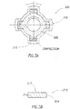
- Figure 1A is an illustration of a view corresponding to section A-A of a turbine blade of the turbine 125, in accordance with certain embodiments of the present disclosure.
- a rotor 130 may be disposed within the housing 110 to provide a non-contact inertia drive.
- the rotor 130 may be suitably spaced so that non-contact magnetic coupling elements 135 of the turbine 125 and the rotor 130 do not make contact, but, when sufficient drilling mud flow drives the turbine 125, the turbine 125 in turn drives the rotor 130 via the magnetic coupling of the elements 135.
- the drilling assembly section 100 may be powered by linear energy of the mud flow being transferred to the rotor 130 through the turbine blades and the non-contact magnetic coupling elements 135.
- a magnetic coupling is disclosed with this example, that type of coupling should not be seen as limiting.
- Alternative embodiments may include any other suitable type of coupling.
- Coupled to the rotor 130 may be a rotating array 140.
- the array 140 may include a plurality of beams, each of which may have magnetic material 142 at one or both ends. As such, the array 140 may be a rotating magnet array.
- the array 140 may be disposed within a carriage 145, which may surround the array 140 and a portion of the rotor 130. The carriage 145 may be fixed to the housing 110 and may remain stationary while the array 140 and rotor 130 rotate.
- Affixed to the carriage 145 may be one or more magnetostrictive beam arrays 150.
- the magnetostrictive beam arrays 150 may include a plurality of beams 152, each beam 152 affixed to the carriage 145 at a one end.
- Figure 1B is an illustration of a magnetostrictive beam 152 affixed to the carriage 145 at one end, in accordance with certain embodiments of the present disclosure.
- Each beam 152 may include magnetostrictive material.
- the magnetostrictive beam arrays 150 may be coupled to the array 140, where coupling means magnetically or inductively coupled.
- the magnetic material 142 may likewise rotate past the magnetostrictive beam arrays 150 without making contact with the magnetostrictive beam arrays 150.
- the resulting oscillating magnetic field may cause alternating strain and relaxation of the beams 152.
- the magnetostrictive material of the beams 152 may generate magnetic fields.
- about each beam 152 may be disposed a wire coil 154, a conductor in which the magnetic field of the beam 152 may induce an electric current.
- Each wire coil 154 and beam 152 may be coupled to allow current to be induced, which includes being coupled in direct contact or coupled magnetically or inductively, for example. Accordingly, with drilling assembly section 100, one method of harvesting the mechanical energy and generating electrical power includes using the mechanical energy of the mud flow to ultimately induce oscillating strain in the magnetostrictive beam arrays 150. In an alternative embodiment, an array of magnets may be affixed directly to the rotor 130 and disposed to alternately compress and relax the magnetostrictive beam arrays 150.
- FIG 2 is an illustration of an example drilling assembly section 200, in accordance with certain embodiments of the present disclosure.
- the drilling assembly section 200 may be similar to the drilling assembly section 100 with respect to certain features, such as being part of a larger drill string assembly, being disposed near the bottom of a wellbore, and may include a collar 205, a housing 210, an annulus 220, and a turbine 225 with a rotor 230 and non-contact magnetic coupling elements 235 to provide a non-contact inertia drive when sufficient drilling mud flow drives the turbine 225.
- a magnetic coupling is disclosed with this example, that type of coupling should not be seen as limiting.
- Alternative embodiments may include any other suitable type of coupling.
- Coupled to the rotor 230 may be an imbalanced rotary load 240.
- the load 240 may take any suitable eccentric form that produces an imbalanced load when rotating with the rotor 230.
- An end portion the imbalanced rotary load 240 may be coupled to a bearing assembly 245.
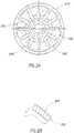
- Figure 2A is an illustration of a view corresponding to section A-A of the example drilling assembly section 200, in accordance with certain embodiments of the present disclosure.
- a carriage 250 may be fixed to the housing 210 and may remain stationary while the imbalanced rotary load 240 and rotor 230 rotate. Attached to the carriage 250 may be a circular array 255 of beams 256, each of which may include magnetostrictive material.
- Figure 2B is an illustration of a detailed view of a component of the circular array 255, in accordance with certain embodiments of the present disclosure. As shown in Figure 2B , about each beam 256 may be disposed a wire coil 257.
- the imbalanced rotary load 240 rotates, the resulting forces may be transferred to the array 255 via the bearing assembly 245, thereby repeatedly causing alternating compression and relaxation of the beams 256.
- the repeated strain induced in the magnetostrictive material may induce an electric current in the conductive wire coils 257.
- the eccentric weighting of the imbalanced rotary load 240 allows for inducing strain on the magnetostrictive material upon sufficient rotation of the rotor 230.
- one method of harvesting the mechanical energy and generating electrical power is by using the mechanical energy of the mud flow to ultimately induce oscillating strain in the magnetostrictive beam array 255.
- FIG. 3 is an illustration of an example drilling assembly section 300, in accordance with certain embodiments of the present disclosure.
- mechanical energy may be typically generated as a result of a variety of forces bearing on a drilling assembly section.
- the drilling assembly section may be subject to varying compression due to stabilizer(s) contacting the borehole wall.
- the points in the drilling hole assembly where the mechanical energy is being generated vary during the drilling process. If no special provisions are made, mechanical energy generation may not occur at all, or may occur but at insufficient levels to generate the electric energy sought.
- Certain embodiments according to the present disclosure provide for special provisions to ensure sufficient mechanical and electrical energy is generated at a point where magnetostrictive technology is deployed.
- the drilling assembly section 300 may be part of a larger drill string assembly that may be suspended in a wellbore, and the drilling assembly section 300 may be disposed near the bottom of the wellbore.
- the drilling assembly section 300 may be may be coupled directly or indirectly to a drill bit (not shown).
- the drilling assembly section 300 may include a collar 305.
- a stabilizer 310 may be attached to the collar 305.
- the stabilizer 310 may be adapted to surround the collar 305 and may be a single piece or may comprise multiple pieces secured to the collar 305 in any suitably secure manner.
- the stabilizer 310 may be a non-rotating stabilizer that extends radially from the collar 305 to a surface of the formation 320.
- the stabilizer 310 may be a rotating stabilizer that rotates with the collar 305 and repeatedly contacts a surface of the formation 320.
- Figure 3A is an illustration of a view corresponding to section A-A of the example drilling assembly section 300, in accordance with certain embodiments of the present disclosure.
- One or more magnetostrictive devices 315 may be embedded, or partially embedded, in the collar 305 with portions of the magnetostrictive devices 315 directly or indirectly contacting the stabilizer 310.
- Figure 3B is an illustration of a detailed view of a component of a magnetostrictive device 315, in accordance with certain embodiments of the present disclosure.
- Each magnetostrictive device 315 may include a magnetostrictive material 316 surrounded by a wire coil 317.
- the magnetostrictive material 316 may be in any suitable form and, in certain embodiments, may be in the form of a rod.
- the wire coil 317 forms the electrical connection of the magnetostrictive device 315.
- one method of harvesting the mechanical energy and generating electrical power is by disposing one or more magnetostrictive devices 315 between the collar 305 and the stabilizer 310.
- the points in a typical drill string where compressive energy is generated may vary during the drilling process.
- the stabilizer 310 imparts a compressive load on the magnetostrictive devices 315 as the stabilizer 310 impacts a surface of the formation 320.
- Sufficient compressive load may cause resulting strain in the one or more magnetostrictive devices 315.
- the magnetostrictive material 316 of a magnetostrictive device 315 may generate a magnetic field, and an electric current is produced in the coils 317 of the magnetostrictive device 315.
- the drilling assembly section 200 provides a stabilizer generator that transfers forces from the stabilizer 310 impacting the formation 320 to the magnetostrictive devices 315.
- the stabilizer 310 moves relative to the collar 305 to strain the magnetostrictive material 316 of the magnetostrictive devices 315 to alter the magnetic domains and thereby induce electrical current the coils 317.
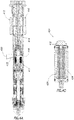
- FIG 4 is an illustration of a partial cross-sectional view of an example downhole assembly section 400, in accordance with certain embodiments of the present disclosure.
- the downhole assembly 400 includes a flow way 402 formed in the downhole component 400 to accommodate the flow of drilling mud.
- the downhole assembly section 400 may include a sonde pressure housing 404 disposed in the flow way 402.
- the sonde pressure housing 404 may include a stator 405 having multiple stator blades 406 extending from the stator 405 into the flow way 402 to accelerate and turn the mud flow to a more suitable velocity and angle of incidence as the mud flow exits the stator 405 and enters the impeller 408.
- the sonde pressure housing 404 may also include an impeller 408 having multiple impeller blades 410 extending from the impeller 408 into the flow way 402 to convert energy of the mud flow as it exits the stator 405 into rotational energy.
- Multiple magnets 412 may be attached to the impeller 408.
- a shaft 414 may be disposed inside the sonde pressure housing 404, the shaft 414 having multiple magnets 416 attached thereto. The shaft 414 may be suitably spaced to not contact the impeller 408.
- the impeller 408 with magnets 412 and the shaft 414 with magnets 416 may be disposed within the housing 410 to provide a non-contact inertia drive.
- the impeller 408 With sufficient drilling mud flow driving the impeller 408, the impeller 408 in turn drives the shaft 414 via the magnetic coupling of the magnets 412 and 416.
- a magnetic coupling is disclosed with this example, that type of coupling should not be seen as limiting.
- Alternative embodiments may include any other suitable type of coupling.
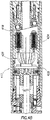
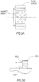
- FIG. 4A is an illustration of a detailed partial cross-sectional view of the sonde pressure housing 404 with a magnetostrictive generator 417, in accordance with certain embodiments of the present disclosure.
- a swash plate 418 may be coupled to the shaft 414 to rotate with rotation of the shaft 414.
- the swash plate 418 may be oriented at a swash plate angle 420 with respect to a plane perpendicular to the longitudinal axis of the shaft 414 and a swash plate bearing surface 422. As the shaft 414 and swash plate 418 rotate, a portion of the swash plate 418 that is distal from the shaft 414 rotates about the axis of shaft rotation.
- Adjacent to the swash plate 418 may be one or more magnetostrictive devices 424 disposed to be alternately compressed and relaxed by the rotating distal portion of the swash plate 418.
- the one or more magnetostrictive devices 424 may be disposed to be alternately flexed and relaxed by the rotating distal portion of the swash plate 418.
- Figure 4B is an illustration of a detailed partial cross-sectional view of the sonde pressure housing 404 with a magnetostrictive generator 417, in accordance with certain embodiments of the present disclosure.
- Electrical connections 426 may couple the one or more magnetostrictive devices 424 to power conditioning electronics 428, which may be configured to receive induced electrical current from the magnetostrictive devices 424 and provide a conditioned output.
- the swash plate 418 is depicted at an exemplary angle with respect to the longitudinal axis of the downhole assembly section 400, the swash plate 418 may be oriented at any suitable angle. Moreover, one or more of the angle of the swash plate 418, the displacement of the one or more magnetostrictive devices 424, the turbine blade angles, and flow rate may be selected as needed to produce a desired amount of power and/or avoid excess power production that would require dissipation or shunting. In certain embodiments, the flow rate, turbine blade angles, and/or swash plate angle may be adjusted downhole.
- FIG. 4C is an illustration of a detailed view of a magnetostrictive device 424, in accordance with certain embodiments of the present disclosure.
- the magnetostrictive material 426 may be in the form of a rod, for example.
- a wire coil 428 about the magnetostrictive material 426 may form the electrical connection of the magnetostrictive device 424.
- the magnetostrictive material 426 and the wire coil 428 may be housed within a housing assembly 430.
- a button assembly 432 may be coupled to the magnetostrictive material 426 and arranged to receive external forces and transfer corresponding axially directed forces to compress the magnetostrictive material 426. Sufficient compressive load transferred from the button assembly 432 may cause resulting strain in the magnetostrictive material 426. In response to that strain, the magnetostrictive material 426 may generate a magnetic field to produce an electric current in the wire coil 428. Electrical leads of the wire coil 428 may be disposed for connections at the end of the housing 430 generally opposite the button assembly 432.
- the magnetostrictive material 426 of the devices 424 produces corresponding repetitive electric currents.
- the electrical currents may be provided to the power conditioning electronics 428, which in turn may provide a conditioned output for powering one or more devices downhole.
- the sonde pressure housing 404 provides a magnetostrictive generator 417 that harvests the mechanical energy of the mud flow and generates electrical power by using the mechanical energy of the mud flow to ultimately induce oscillating strain in the magnetostrictive devices 424.
- the electrical power can be used to power any downhole device such as logging while drilling, measurement while drilling, rotary steerable or other tools that are well known in the art.
- the electrical power can also be used to store energy in downhole rechargeable batteries to provide electrical power when the mud flow is off or to supplement power when needed such as peak demands or in case of a failure of the magnetostrictive generator where the batteries might serve as emergency power.
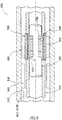
- FIG. 5 is an illustration of an example drilling assembly section 500 in accordance with certain embodiments of the present disclosure.
- the drilling assembly section 500 may be part of a larger drill string assembly that, for example, may be suspended in a wellbore by a derrick (not shown).
- the drilling assembly section 500 may be disposed near the bottom of the wellbore.
- the drilling assembly section 500 may include a collar 505 having disposed therein a housing 510, which may be a sonde pressure housing. Between the collar 505 and housing 510 may be formed an annulus 520 to accommodate the flow of drilling mud therethrough.
- a turbine 525 may be disposed within the collar 505 and may have a plurality of turbine blades 526, each curved so as to rotate the turbine 525 due to sufficient mud flow through the annulus 520.
- the turbine blades 526 may be similar to those shown in Figure 1A and may have a particular right hand or left orientation to function as a flow rotor.
- a flow stator 530 may be affixed to the collar 505 have having multiple stator blades extending in a particular right hand or left orientation into the flow way to accelerate and turn the mud flow to a more suitable velocity and angle of incidence as the mud flow exits the stator 530 and enters the turbine blades 526.
- Coupled to the turbine 525 may be a rotating array 540 of magnetic material 542.
- Figure 5A shows one non-limiting example of a magnetic array and flow rotor configuration.
- the array 540 may be a rotating magnet array.
- the array 540 may be disposed around housing 510.
- a carriage 545 may be positioned within array 540 inside the housing 510.
- the carriage 545 may be fixed to the housing 510 and may remain stationary while the array 540 rotates.
- Affixed to the carriage 545 may be one or more magnetostrictive beam arrays 550.
- the magnetostrictive beam arrays 550 may include a plurality of beams 552, each beam 552 affixed to the carriage 545.
- Figure 5B is an illustration of a magnetostrictive beam assembly where a magnetostrictive beam 552 may be affixed to the carriage 545 at one end, in accordance with certain embodiments of the present disclosure.
- Each beam 552 may include magnetostrictive material and may have one or more wire coils 554 disposed around it for electrical output.
- Each beam 552 may include a magnet or magnetic material cap 553.
- the magnetic material 542 may likewise rotate past the magnetostrictive beam arrays 550 without making contact with the magnetostrictive beam arrays 550.
- the resulting oscillating magnetic field may cause alternating strain and relaxation of the beams 552.
- the magnetostrictive material of the beams 552 may generate magnetic fields.
- about each beam 552 may be disposed a wire coil 554 in which the magnetic field of the beam 552 may induce an electric current. Accordingly, with drilling assembly section 500, one method of harvesting the mechanical energy and generating electrical power is by using the mechanical energy of the mud flow to ultimately induce oscillating strain in the magnetostrictive beam arrays 550.
- an array of magnets may be affixed to the turbine and adapted to apply an oscillating magnetic field to the magnetostrictive beam array through the wall of the sonde pressure housing, thereby inducing strain in the magnetostrictive material inside the sonde pressure housing.
- certain embodiments of the present disclosure allow for harvesting mechanical energy downhole and generating electrical power therefrom.
- the figures depict embodiments of the present disclosure in a horizontal orientation it should be understood by those skilled in the art that embodiments of the present disclosure are well suited for use in a variety of orientations. Accordingly, it should be understood by those skilled in the art that the use of directional terms such as above, below, upper, lower, upward, downward and the like are used in relation to the illustrative embodiments as they are depicted in the figures, the upward direction being toward the top of the corresponding figure and the downward direction being toward the bottom of the corresponding figure.
Abstract
Description
- This application claims the benefit of
U.S. Provisional Application No. 61/451,483, which was filed March 10, 2011 - The present disclosure relates generally to wellbore operations and, more particularly, to systems and methods of harvesting energy in a wellbore.
- Power for use in a downhole environment has generally in the past been either stored in a device, such as a battery, and conveyed downhole or it has been transmitted via conductors, such as a wireline, from the space or another remote location. As is well known, batteries have the capability of storing only a finite amount of power therein and have environmental limits, such as temperature, on their use.
- Electrical conductors, such as those in a conventional wireline, provide a practically unlimited amount of power, but require special facilities at the surface for deployment and typically obstruct the production flowpath, thereby preventing the use of safety valves, limiting the flow rate of fluids through the flowpath, etc., while the conductors are in the flowpath. Thus, wireline operations are typically carried out prior to the production phase of a well, or during remedial operations after the well has been placed into production.
- In wellbore drilling operations, it is desirable to provide one or more efficient power sources downhole, for example, to power downhole instrumentation. A wide variety of devices may use mechanical energy in order to perform work downhole. Those devices may be subject to a variety of forces and may release energy in a number of ways. What is needed is a method of harvesting mechanical energy downhole and generating electrical power therefrom.
- Some specific exemplary embodiments of the disclosure may be understood by referring, in part, to the following description and the accompanying drawings.
-
Figure 1 is an illustration of an example drilling assembly section, in accordance with certain embodiments of the present disclosure. -
Figure 1A is an illustration of a partial sectional view of the example drilling assembly section ofFigure 1 , in accordance with certain embodiments of the present disclosure. -
Figure 1B is an illustration of a partial detailed view of the example drilling assembly section ofFigure 1 , in accordance with certain embodiments of the present disclosure. -
Figure 2 is an illustration of an example drilling assembly section, in accordance with certain embodiments of the present disclosure. -
Figure 2A is an illustration of a partial sectional view of the example drilling assembly section ofFigure 2 , in accordance with certain embodiments of the present disclosure. -
Figure 2B is an illustration of a partial detailed view of the example drilling assembly section ofFigure 2 , in accordance with certain embodiments of the present disclosure. -
Figure 3 is an illustration of an example drilling assembly section, in accordance with certain embodiments of the present disclosure. -
Figure 3A is an illustration of a partial sectional view of the example drilling assembly section ofFigure 3 , in accordance with certain embodiments of the present disclosure. -
Figure 3B is an illustration of a detailed view of the example drilling assembly section ofFigure 3 , in accordance with certain embodiments of the present disclosure. -
Figure 4 is an illustration of a partial cross-sectional view of an example downhole assembly section, in accordance with certain embodiments of the present disclosure. -
Figure 4A is an illustration of a detailed partial cross-sectional view of the downhole assembly section ofFigure 4 , in accordance with certain embodiments of the present disclosure. -
Figure 4B is an illustration of another detailed partial cross-sectional view of the downhole assembly section ofFigure 4 , in accordance with certain embodiments of the present disclosure. -
Figure 4C is an illustration of another detailed partial cross-sectional view of the downhole assembly section ofFigure 4 , in accordance with certain embodiments of the present disclosure. -
Figure 5 is an illustration of an example drilling assembly section, in accordance with certain embodiments of the present disclosure. -
Figure 5A is an illustration of a partial sectional view of the example drilling assembly section ofFigure 5 , in accordance with certain embodiments of the present disclosure. -
Figure 5B is an illustration of a partial detailed view of the example drilling assembly section ofFigure 5 , in accordance with certain embodiments of the present disclosure. - While embodiments of this disclosure have been depicted and described and are defined by reference to exemplary embodiments of the disclosure, such references do not imply a limitation on the disclosure, and no such limitation is to be inferred. The subject matter disclosed is capable of considerable modification, alteration, and equivalents in form and function, as will occur to those skilled in the pertinent art and having the benefit of this disclosure. The depicted and described embodiments of this disclosure are examples only, and not exhaustive of the scope of the disclosure.
- The present disclosure relates generally to wellbore operations and, more particularly, to systems and methods of harvesting energy in a wellbore.
- Illustrative embodiments of the present disclosure are described in detail herein. In the interest of clarity, not all features of an actual implementation may be described in this specification. It will of course be appreciated that in the development of any such actual embodiment, numerous implementation specific decisions must be made to achieve the specific implementation goals, which will vary from one implementation to another. Moreover, it will be appreciated that such a development effort might be complex and time consuming, but would nevertheless be a routine undertaking for those of ordinary skill in the art having the benefit of the present disclosure.
- To facilitate a better understanding of the present disclosure, the following examples of certain embodiments are given. In no way should the following examples be read to limit, or define, the scope of the disclosure. Embodiments of the present disclosure may be applicable to horizontal, vertical, deviated, or otherwise nonlinear wellbores in any type of subterranean formation. Embodiments may be applicable to injection wells as well as production wells, including hydrocarbon wells. Devices and methods in accordance with certain embodiments may be used in one or more of wireline, measurement-while-drilling (MWD) and logging-while-drilling (LWD) operations.
- In certain embodiments according to the present disclosure, magnetostrictive technology may be capable of generating electrical power during the process of drilling a borehole by using the mechanical energy generated in a downhole drilling assembly. Magnetostrictive materials have the ability to convert kinetic energy into magnetic energy that may be used to generate electrical power. Magnetostrictive materials have the property that, when strain is induced in the material, the change in linear dimensions produces a corresponding change in magnetic field about the material. In other words, mechanical loads can deform the material and thereby rotate magnetic domains. The change of the magnetic flux can be used to generate electrical power. A suitable material for the magnetostrictive material may be Terfenol-D, available from Etrema Products, Inc. Various materials, e.g., iron and iron alloys such as Terfenol, may provide suitable magnetostrictive and giant magnetostrictive responses. These materials normally respond to a force applied to their mechanical connection by creating a magnetic field which can be detected, for example, by a surrounding conductor coil.
-
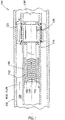
Figure 1 is an illustration of an exampledrilling assembly section 100 in accordance with certain embodiments of the present disclosure. Thedrilling assembly section 100 may be part of a larger drill string assembly that, for example, may be suspended in a wellbore by a derrick (not shown). Thedrilling assembly section 100 may be disposed near the bottom of the wellbore. Thedrilling assembly section 100 may include acollar 105 having disposed therein ahousing 110, which may be a sonde pressure housing. Between thecollar 105 andhousing 110 may be formed anannulus 120 to accommodate the flow of drilling mud therethrough. Aturbine 125 may be disposed within thecollar 105 and may have a plurality of turbine blades, each curved so as to rotate theturbine 125 due to sufficient mud flow through theannulus 120.Figure 1A is an illustration of a view corresponding to section A-A of a turbine blade of theturbine 125, in accordance with certain embodiments of the present disclosure. - As shown in
Figure 1 , arotor 130 may be disposed within thehousing 110 to provide a non-contact inertia drive. Therotor 130 may be suitably spaced so that non-contactmagnetic coupling elements 135 of theturbine 125 and therotor 130 do not make contact, but, when sufficient drilling mud flow drives theturbine 125, theturbine 125 in turn drives therotor 130 via the magnetic coupling of theelements 135. Stated otherwise, thedrilling assembly section 100 may be powered by linear energy of the mud flow being transferred to therotor 130 through the turbine blades and the non-contactmagnetic coupling elements 135. However, while a magnetic coupling is disclosed with this example, that type of coupling should not be seen as limiting. Alternative embodiments may include any other suitable type of coupling. - Coupled to the
rotor 130 may be arotating array 140. Thearray 140 may include a plurality of beams, each of which may havemagnetic material 142 at one or both ends. As such, thearray 140 may be a rotating magnet array. Thearray 140 may be disposed within acarriage 145, which may surround thearray 140 and a portion of therotor 130. Thecarriage 145 may be fixed to thehousing 110 and may remain stationary while thearray 140 androtor 130 rotate. - Affixed to the
carriage 145 may be one or moremagnetostrictive beam arrays 150. Themagnetostrictive beam arrays 150 may include a plurality ofbeams 152, eachbeam 152 affixed to thecarriage 145 at a one end.Figure 1B is an illustration of amagnetostrictive beam 152 affixed to thecarriage 145 at one end, in accordance with certain embodiments of the present disclosure. Eachbeam 152 may include magnetostrictive material. - Accordingly, the
magnetostrictive beam arrays 150 may be coupled to thearray 140, where coupling means magnetically or inductively coupled. As thearray 140 rotates with the rotation of therotor 130, themagnetic material 142 may likewise rotate past themagnetostrictive beam arrays 150 without making contact with themagnetostrictive beam arrays 150. The resulting oscillating magnetic field may cause alternating strain and relaxation of thebeams 152. In response to that oscillating strain, the magnetostrictive material of thebeams 152 may generate magnetic fields. About eachbeam 152 may be disposed awire coil 154, a conductor in which the magnetic field of thebeam 152 may induce an electric current. Eachwire coil 154 andbeam 152 may be coupled to allow current to be induced, which includes being coupled in direct contact or coupled magnetically or inductively, for example. Accordingly, withdrilling assembly section 100, one method of harvesting the mechanical energy and generating electrical power includes using the mechanical energy of the mud flow to ultimately induce oscillating strain in themagnetostrictive beam arrays 150. In an alternative embodiment, an array of magnets may be affixed directly to therotor 130 and disposed to alternately compress and relax themagnetostrictive beam arrays 150. -
Figure 2 is an illustration of an example drilling assembly section 200, in accordance with certain embodiments of the present disclosure. The drilling assembly section 200 may be similar to thedrilling assembly section 100 with respect to certain features, such as being part of a larger drill string assembly, being disposed near the bottom of a wellbore, and may include acollar 205, ahousing 210, anannulus 220, and aturbine 225 with arotor 230 and non-contactmagnetic coupling elements 235 to provide a non-contact inertia drive when sufficient drilling mud flow drives theturbine 225. However, while a magnetic coupling is disclosed with this example, that type of coupling should not be seen as limiting. Alternative embodiments may include any other suitable type of coupling. - Coupled to the
rotor 230 may be an imbalancedrotary load 240. Theload 240 may take any suitable eccentric form that produces an imbalanced load when rotating with therotor 230. An end portion the imbalancedrotary load 240 may be coupled to abearing assembly 245.Figure 2A is an illustration of a view corresponding to section A-A of the example drilling assembly section 200, in accordance with certain embodiments of the present disclosure. - A
carriage 250 may be fixed to thehousing 210 and may remain stationary while the imbalancedrotary load 240 androtor 230 rotate. Attached to thecarriage 250 may be a circular array 255 ofbeams 256, each of which may include magnetostrictive material.Figure 2B is an illustration of a detailed view of a component of the circular array 255, in accordance with certain embodiments of the present disclosure. As shown inFigure 2B , about eachbeam 256 may be disposed awire coil 257. - As the imbalanced
rotary load 240 rotates, the resulting forces may be transferred to the array 255 via the bearingassembly 245, thereby repeatedly causing alternating compression and relaxation of thebeams 256. The repeated strain induced in the magnetostrictive material may induce an electric current in the conductive wire coils 257. Thus, the eccentric weighting of the imbalancedrotary load 240 allows for inducing strain on the magnetostrictive material upon sufficient rotation of therotor 230. Accordingly, with drilling assembly section 200, one method of harvesting the mechanical energy and generating electrical power is by using the mechanical energy of the mud flow to ultimately induce oscillating strain in the magnetostrictive beam array 255. -
Figure 3 is an illustration of an exampledrilling assembly section 300, in accordance with certain embodiments of the present disclosure. In certain embodiments, mechanical energy may be typically generated as a result of a variety of forces bearing on a drilling assembly section. For example, the drilling assembly section may be subject to varying compression due to stabilizer(s) contacting the borehole wall. The points in the drilling hole assembly where the mechanical energy is being generated vary during the drilling process. If no special provisions are made, mechanical energy generation may not occur at all, or may occur but at insufficient levels to generate the electric energy sought. Certain embodiments according to the present disclosure provide for special provisions to ensure sufficient mechanical and electrical energy is generated at a point where magnetostrictive technology is deployed. - As with the
drilling assembly section 100, thedrilling assembly section 300 may be part of a larger drill string assembly that may be suspended in a wellbore, and thedrilling assembly section 300 may be disposed near the bottom of the wellbore. Thedrilling assembly section 300 may be may be coupled directly or indirectly to a drill bit (not shown). Thedrilling assembly section 300 may include acollar 305. Astabilizer 310 may be attached to thecollar 305. Thestabilizer 310, for example, may be adapted to surround thecollar 305 and may be a single piece or may comprise multiple pieces secured to thecollar 305 in any suitably secure manner. In certain embodiments, thestabilizer 310 may be a non-rotating stabilizer that extends radially from thecollar 305 to a surface of theformation 320. In certain embodiments, thestabilizer 310 may be a rotating stabilizer that rotates with thecollar 305 and repeatedly contacts a surface of theformation 320.Figure 3A is an illustration of a view corresponding to section A-A of the exampledrilling assembly section 300, in accordance with certain embodiments of the present disclosure. - One or more
magnetostrictive devices 315 may be embedded, or partially embedded, in thecollar 305 with portions of themagnetostrictive devices 315 directly or indirectly contacting thestabilizer 310.Figure 3B is an illustration of a detailed view of a component of amagnetostrictive device 315, in accordance with certain embodiments of the present disclosure. Eachmagnetostrictive device 315 may include amagnetostrictive material 316 surrounded by awire coil 317. Themagnetostrictive material 316 may be in any suitable form and, in certain embodiments, may be in the form of a rod. Thewire coil 317 forms the electrical connection of themagnetostrictive device 315. - With the
drilling assembly section 300, one method of harvesting the mechanical energy and generating electrical power is by disposing one or moremagnetostrictive devices 315 between thecollar 305 and thestabilizer 310. The points in a typical drill string where compressive energy is generated may vary during the drilling process. However, with thedrilling assembly section 300, thestabilizer 310 imparts a compressive load on themagnetostrictive devices 315 as thestabilizer 310 impacts a surface of theformation 320. Sufficient compressive load may cause resulting strain in the one or moremagnetostrictive devices 315. In response to that strain, themagnetostrictive material 316 of amagnetostrictive device 315 may generate a magnetic field, and an electric current is produced in thecoils 317 of themagnetostrictive device 315. Thus, as thedrilling assembly section 300 repetitively impacts theformation 320, the one or moremagnetostrictive devices 315 produce corresponding repetitive electric currents. Accordingly, the drilling assembly section 200 provides a stabilizer generator that transfers forces from thestabilizer 310 impacting theformation 320 to themagnetostrictive devices 315. Thestabilizer 310 moves relative to thecollar 305 to strain themagnetostrictive material 316 of themagnetostrictive devices 315 to alter the magnetic domains and thereby induce electrical current thecoils 317. -
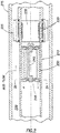
Figure 4 is an illustration of a partial cross-sectional view of an exampledownhole assembly section 400, in accordance with certain embodiments of the present disclosure. Thedownhole assembly 400 includes aflow way 402 formed in thedownhole component 400 to accommodate the flow of drilling mud. Thedownhole assembly section 400 may include asonde pressure housing 404 disposed in theflow way 402. Thesonde pressure housing 404 may include astator 405 havingmultiple stator blades 406 extending from thestator 405 into theflow way 402 to accelerate and turn the mud flow to a more suitable velocity and angle of incidence as the mud flow exits thestator 405 and enters theimpeller 408. Thesonde pressure housing 404 may also include animpeller 408 havingmultiple impeller blades 410 extending from theimpeller 408 into theflow way 402 to convert energy of the mud flow as it exits thestator 405 into rotational energy.Multiple magnets 412 may be attached to theimpeller 408. Ashaft 414 may be disposed inside thesonde pressure housing 404, theshaft 414 havingmultiple magnets 416 attached thereto. Theshaft 414 may be suitably spaced to not contact theimpeller 408. Theimpeller 408 withmagnets 412 and theshaft 414 withmagnets 416 may be disposed within thehousing 410 to provide a non-contact inertia drive. With sufficient drilling mud flow driving theimpeller 408, theimpeller 408 in turn drives theshaft 414 via the magnetic coupling of themagnets -
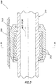
Figure 4A is an illustration of a detailed partial cross-sectional view of thesonde pressure housing 404 with amagnetostrictive generator 417, in accordance with certain embodiments of the present disclosure. Aswash plate 418 may be coupled to theshaft 414 to rotate with rotation of theshaft 414. Theswash plate 418 may be oriented at aswash plate angle 420 with respect to a plane perpendicular to the longitudinal axis of theshaft 414 and a swashplate bearing surface 422. As theshaft 414 andswash plate 418 rotate, a portion of theswash plate 418 that is distal from theshaft 414 rotates about the axis of shaft rotation. - Adjacent to the
swash plate 418 may be one or moremagnetostrictive devices 424 disposed to be alternately compressed and relaxed by the rotating distal portion of theswash plate 418. In an alternative embodiment, the one or moremagnetostrictive devices 424 may be disposed to be alternately flexed and relaxed by the rotating distal portion of theswash plate 418. -
Figure 4B is an illustration of a detailed partial cross-sectional view of thesonde pressure housing 404 with amagnetostrictive generator 417, in accordance with certain embodiments of the present disclosure.Electrical connections 426 may couple the one or moremagnetostrictive devices 424 topower conditioning electronics 428, which may be configured to receive induced electrical current from themagnetostrictive devices 424 and provide a conditioned output. - While the
swash plate 418 is depicted at an exemplary angle with respect to the longitudinal axis of thedownhole assembly section 400, theswash plate 418 may be oriented at any suitable angle. Moreover, one or more of the angle of theswash plate 418, the displacement of the one or moremagnetostrictive devices 424, the turbine blade angles, and flow rate may be selected as needed to produce a desired amount of power and/or avoid excess power production that would require dissipation or shunting. In certain embodiments, the flow rate, turbine blade angles, and/or swash plate angle may be adjusted downhole. -
Figure 4C is an illustration of a detailed view of amagnetostrictive device 424, in accordance with certain embodiments of the present disclosure. Themagnetostrictive material 426 may be in the form of a rod, for example. Awire coil 428 about themagnetostrictive material 426 may form the electrical connection of themagnetostrictive device 424. Themagnetostrictive material 426 and thewire coil 428 may be housed within a housing assembly 430. Abutton assembly 432 may be coupled to themagnetostrictive material 426 and arranged to receive external forces and transfer corresponding axially directed forces to compress themagnetostrictive material 426. Sufficient compressive load transferred from thebutton assembly 432 may cause resulting strain in themagnetostrictive material 426. In response to that strain, themagnetostrictive material 426 may generate a magnetic field to produce an electric current in thewire coil 428. Electrical leads of thewire coil 428 may be disposed for connections at the end of the housing 430 generally opposite thebutton assembly 432. - Thus, as the
swash plate 418 repetitively impacts thebutton assembly 432 of the one or moremagnetostrictive devices 424, themagnetostrictive material 426 of thedevices 424 produces corresponding repetitive electric currents. The electrical currents may be provided to thepower conditioning electronics 428, which in turn may provide a conditioned output for powering one or more devices downhole. Accordingly, thesonde pressure housing 404 provides amagnetostrictive generator 417 that harvests the mechanical energy of the mud flow and generates electrical power by using the mechanical energy of the mud flow to ultimately induce oscillating strain in themagnetostrictive devices 424. - The electrical power can be used to power any downhole device such as logging while drilling, measurement while drilling, rotary steerable or other tools that are well known in the art. The electrical power can also be used to store energy in downhole rechargeable batteries to provide electrical power when the mud flow is off or to supplement power when needed such as peak demands or in case of a failure of the magnetostrictive generator where the batteries might serve as emergency power.
-
Figure 5 is an illustration of an exampledrilling assembly section 500 in accordance with certain embodiments of the present disclosure. Thedrilling assembly section 500 may be part of a larger drill string assembly that, for example, may be suspended in a wellbore by a derrick (not shown). Thedrilling assembly section 500 may be disposed near the bottom of the wellbore. Thedrilling assembly section 500 may include acollar 505 having disposed therein ahousing 510, which may be a sonde pressure housing. Between thecollar 505 andhousing 510 may be formed anannulus 520 to accommodate the flow of drilling mud therethrough. Aturbine 525 may be disposed within thecollar 505 and may have a plurality ofturbine blades 526, each curved so as to rotate theturbine 525 due to sufficient mud flow through theannulus 520. Theturbine blades 526 may be similar to those shown inFigure 1A and may have a particular right hand or left orientation to function as a flow rotor. Aflow stator 530 may be affixed to thecollar 505 have having multiple stator blades extending in a particular right hand or left orientation into the flow way to accelerate and turn the mud flow to a more suitable velocity and angle of incidence as the mud flow exits thestator 530 and enters theturbine blades 526. - Coupled to the
turbine 525 may be arotating array 540 ofmagnetic material 542.Figure 5A shows one non-limiting example of a magnetic array and flow rotor configuration. As such, thearray 540 may be a rotating magnet array. Thearray 540 may be disposed aroundhousing 510. Acarriage 545 may be positioned withinarray 540 inside thehousing 510. Thecarriage 545 may be fixed to thehousing 510 and may remain stationary while thearray 540 rotates. - Affixed to the
carriage 545 may be one or moremagnetostrictive beam arrays 550. Themagnetostrictive beam arrays 550 may include a plurality ofbeams 552, eachbeam 552 affixed to thecarriage 545.Figure 5B is an illustration of a magnetostrictive beam assembly where amagnetostrictive beam 552 may be affixed to thecarriage 545 at one end, in accordance with certain embodiments of the present disclosure. Eachbeam 552 may include magnetostrictive material and may have one or more wire coils 554 disposed around it for electrical output. Eachbeam 552 may include a magnet ormagnetic material cap 553. - As the
array 540 rotates with the rotation of theturbine 525, themagnetic material 542 may likewise rotate past themagnetostrictive beam arrays 550 without making contact with themagnetostrictive beam arrays 550. The resulting oscillating magnetic field may cause alternating strain and relaxation of thebeams 552. In response to that oscillating strain, the magnetostrictive material of thebeams 552 may generate magnetic fields. About eachbeam 552 may be disposed awire coil 554 in which the magnetic field of thebeam 552 may induce an electric current. Accordingly, withdrilling assembly section 500, one method of harvesting the mechanical energy and generating electrical power is by using the mechanical energy of the mud flow to ultimately induce oscillating strain in themagnetostrictive beam arrays 550. In this embodiment, an array of magnets may be affixed to the turbine and adapted to apply an oscillating magnetic field to the magnetostrictive beam array through the wall of the sonde pressure housing, thereby inducing strain in the magnetostrictive material inside the sonde pressure housing. - Accordingly, certain embodiments of the present disclosure allow for harvesting mechanical energy downhole and generating electrical power therefrom. And even though the figures depict embodiments of the present disclosure in a horizontal orientation, it should be understood by those skilled in the art that embodiments of the present disclosure are well suited for use in a variety of orientations. Accordingly, it should be understood by those skilled in the art that the use of directional terms such as above, below, upper, lower, upward, downward and the like are used in relation to the illustrative embodiments as they are depicted in the figures, the upward direction being toward the top of the corresponding figure and the downward direction being toward the bottom of the corresponding figure.
- Therefore, the present disclosure is well adapted to attain the ends and advantages mentioned as well as those that are inherent therein. The particular embodiments disclosed above are illustrative only, as the present disclosure may be modified and practiced in different but equivalent manners apparent to those skilled in the art having the benefit of the teachings herein. Furthermore, no limitations are intended to the details of construction or design herein shown, other than as described in the claims below. It is therefore evident that the particular illustrative embodiments disclosed above may be altered or modified and all such variations are considered within the scope and spirit of the present disclosure. Also, the terms in the claims have their plain, ordinary meaning unless otherwise explicitly and clearly defined by the patentee. The indefinite articles "a" or "an," as used in the claims, are defined herein to mean one or more than one of the element that it introduces.
Claims (15)
- A downhole assembly comprising:a turbine to be disposed within a wellbore;a rotating array comprising magnetic material and coupled to the turbine; anda magnetostrictive material coupled to the rotating array to:strain the magnetostrictive material; andinduce an electric current in a conductor coupled to the magnetostrictive material.
- The downhole assembly of claim 1, further comprising:a rotor coupled to the turbine, wherein the rotating array is coupled to the rotor.
- The downhole assembly of claim 2, wherein the turbine drives the rotor via a magnetic coupling element in response to fluid flow within the wellbore.
- The downhole assembly of any preceding claim, wherein the magnetostrictive material is disposed radially exterior to the rotating array.
- The downhole assembly of any one of claims 1 to 3, wherein the magnetostrictive material is disposed radially interior to the rotating array.
- The downhole assembly of any preceding claim, wherein the magnetostrictive material is included in a magnetostrictive beam array.
- The downhole assembly of claim 6, wherein the rotating array includes a plurality of beams, wherein one or more of the beams have an end including the magnetic material.
- A downhole assembly to harvest energy in a wellbore, the downhole assembly comprising:a turbine to be disposed within a wellbore;a rotor coupled to the turbine; andan imbalanced rotary load disposed proximate to magnetostrictive material and coupled to the rotor so that the imbalanced rotary load rotates in response to fluid flow within the collar rotating the turbine;wherein, consequent to the rotation of the imbalanced rotary load, resulting forces strain the magnetostrictive material, thereby inducing an electrical current in a conductor disposed proximate to the magnetostrictive material.
- The downhole assembly of claim 9, wherein the turbine drives the rotor via a magnetic coupling element in response to fluid flow within the wellbore.
- The downhole assembly of claim 8 or 9, further comprising:a carriage in which the imbalanced rotary load is disposed, wherein the magnetostrictive material is included in a magnetostrictive beam array coupled to the carriage.
- The downhole assembly of any one of claims 8, 9 or 10, further comprising:a bearing assembly coupled to an end of the imbalance rotary load.
- A downhole assembly to harvest energy in a wellbore, the downhole assembly comprising:an impeller to be disposed in a wellbore;a shaft coupled to the impeller and disposed within a housing;a swash plate coupled to the shaft and having a surface disposed at an angle with respect to an axis of the shaft; anda magnetostrictive device proximate to the swash plate and comprising magnetostrictive material and a conductor proximate to the magnetostrictive material;wherein the impeller drives the shaft in response to fluid flow in the wellbore; andwherein the swash plate rotates with a rotation of the shaft, and the surface of the swash plate imparts an alternating compressive load to the magnetostrictive material, thereby inducing an electrical current in the conductor.
- The downhole assembly of claim 12, wherein the impeller is coupled to the shaft disposed to provide a non-contact inertia drive.
- The downhole assembly of claim 12 or 13, wherein the magnetostrictive material is in form of a rod.
- The downhole assembly of any one of claims 12 to 14, wherein the magnetostrictive device further comprises:a housing about the magnetostrictive material; anda button assembly couple to the magnetostrictive material to transfer the alternating compressive load to the magnetostrictive material.
Applications Claiming Priority (2)
| Application Number | Priority Date | Filing Date | Title |
|---|---|---|---|
| US201161451483P | 2011-03-10 | 2011-03-10 | |
| US13/242,716 US8604632B2 (en) | 2011-03-10 | 2011-09-23 | Systems and methods of harvesting energy in a wellbore |
Publications (3)
| Publication Number | Publication Date |
|---|---|
| EP2497899A2 true EP2497899A2 (en) | 2012-09-12 |
| EP2497899A3 EP2497899A3 (en) | 2015-01-21 |
| EP2497899B1 EP2497899B1 (en) | 2016-04-27 |
Family
ID=45833211
Family Applications (1)
| Application Number | Title | Priority Date | Filing Date |
|---|---|---|---|
| EP12158783.6A Active EP2497899B1 (en) | 2011-03-10 | 2012-03-09 | Systems and methods of harvesting energy in a wellbore |
Country Status (2)
| Country | Link |
|---|---|
| US (3) | US8604632B2 (en) |
| EP (1) | EP2497899B1 (en) |
Cited By (3)
| Publication number | Priority date | Publication date | Assignee | Title |
|---|---|---|---|---|
| CN106329993A (en) * | 2016-09-14 | 2017-01-11 | 长春工业大学 | Pressure-maintaining speeding-up excitation type energy harvesting device facing low power consumption sensor energy supply |
| CN106357157A (en) * | 2016-09-14 | 2017-01-25 | 长春工业大学 | Porous jet resonant mode piezoelectric harvester |
| WO2023091533A1 (en) * | 2021-11-17 | 2023-05-25 | Schlumberger Technology Corporation | Downhole vibration energy harvester for low power applications |
Families Citing this family (30)
| Publication number | Priority date | Publication date | Assignee | Title |
|---|---|---|---|---|
| WO2012103553A1 (en) * | 2011-01-28 | 2012-08-02 | Oscilla Power Inc. | Energy harvesting methods and devices, and applications thereof |
| US8836179B2 (en) * | 2011-03-10 | 2014-09-16 | Halliburton Energy Services, Inc. | Systems and methods of energy harvesting with positive displacement motor |
| US8686587B2 (en) * | 2011-03-10 | 2014-04-01 | Halliburton Energy Services, Inc. | Power generator for booster amplifier systems |
| US9948213B2 (en) | 2011-03-10 | 2018-04-17 | Halliburton Energy Services, Inc. | Magnetostrictive power supply for bottom hole assembly with rotation-resistant housing |
| US8890341B2 (en) * | 2011-07-29 | 2014-11-18 | Schlumberger Technology Corporation | Harvesting energy from a drillstring |
| US8624419B2 (en) * | 2011-09-01 | 2014-01-07 | Chevron U.S.A., Inc. | Downhole power generation by way of electromagnetic induction |
| US9634233B2 (en) | 2012-07-05 | 2017-04-25 | Oscilla Power, Inc. | Axial loading for magnetostrictive power generation |
| WO2014100267A1 (en) * | 2012-12-18 | 2014-06-26 | Oscilla Power Inc. | Downhole energy harvesting method and device |
| US9634234B2 (en) | 2012-12-18 | 2017-04-25 | Oscilla Power, Inc. | Downhole energy harvesting method and device |
| US20140239745A1 (en) * | 2013-02-26 | 2014-08-28 | Oscilla Power Inc. | Rotary to linear converter for downhole applications |
| US9112389B2 (en) * | 2013-03-25 | 2015-08-18 | Deere & Company | Machine for generating electrical energy or sensing material flow |
| WO2014168007A1 (en) * | 2013-04-12 | 2014-10-16 | ミツミ電機株式会社 | Power generation device |
| EP2988409A4 (en) * | 2013-04-12 | 2017-03-08 | Mitsumi Electric Co., Ltd. | Power generation device |
| US9431928B2 (en) * | 2013-11-06 | 2016-08-30 | Oscilla Power Inc. | Power production in a completed well using magnetostrictive materials |
| US9309862B2 (en) | 2013-11-25 | 2016-04-12 | Halliburton Energy Services, Inc. | Nutating fluid-mechanical energy converter |
| US9657519B2 (en) | 2014-01-30 | 2017-05-23 | Halliburton Energy Services, Inc. | Nutating fluid-mechanical energy converter to power wellbore drilling |
| PL3158159T3 (en) * | 2014-06-17 | 2021-05-04 | Flexidrill Limited | Mechanical force generator |
| US9490728B1 (en) * | 2014-11-20 | 2016-11-08 | The United States Of America As Represented By The Secretary Of The Navy | Magnetoelectric energy harvesting |
| US9837937B2 (en) * | 2014-12-04 | 2017-12-05 | Chevron U.S.A. Inc. | Piezoelectric power generation system |
| CN106230318B (en) * | 2016-09-14 | 2018-03-06 | 长春工业大学 | Vortex-excited oscillation formula piezoelectric harvester for low-power consumption sensor energy supply |
| CN106301075B (en) * | 2016-09-14 | 2018-03-06 | 长春工业大学 | Pneumatic system low energy-consumption electronic device energizes porous flow increasing excitation type piezoelectric harvester |
| CN106230317B (en) * | 2016-09-14 | 2018-02-02 | 长春工业大学 | Porous flow increasing type rotary type piezoelectric generator |
| US10340755B1 (en) * | 2016-11-14 | 2019-07-02 | George R Dreher | Energy harvesting and converting beam pumping unit |
| CA3115951C (en) * | 2017-05-01 | 2022-06-28 | U-Target Energy Ltd. | Downhole telemetry sub for communication with surface |
| CN109026508A (en) * | 2018-08-14 | 2018-12-18 | 沈阳工业大学 | A kind of magnetostriction thin slice float-type wave vibration power generator |
| US11398710B2 (en) * | 2019-05-17 | 2022-07-26 | David Anderson | Protective barrier for the dielectric materials of an electrical connection/interface in an oil well environment and a method of forming the same |
| GB201917357D0 (en) * | 2019-11-28 | 2020-01-15 | Expro North Sea Ltd | Downhole power generation devices and method of generating power downhole |
| US11686196B2 (en) | 2019-12-19 | 2023-06-27 | Saudi Arabian Oil Company | Downhole actuation system and methods with dissolvable ball bearing |
| WO2023101893A1 (en) * | 2021-12-03 | 2023-06-08 | Saudi Arabian Oil Company | Magnetically controlled release of chemicals in a downhole environment |
| CN116505712B (en) * | 2023-06-28 | 2023-08-29 | 西南石油大学 | Underground turbine power generation robot with guide mechanism |
Family Cites Families (27)
| Publication number | Priority date | Publication date | Assignee | Title |
|---|---|---|---|---|
| US2858108A (en) * | 1953-04-22 | 1958-10-28 | Drilling Res Inc | Well drilling system |
| US2825534A (en) * | 1954-09-20 | 1958-03-04 | Phillips Petroleum Co | Apparatus for drilling wells |
| US3036645A (en) * | 1958-12-15 | 1962-05-29 | Jersey Prod Res Co | Bottom-hole turbogenerator drilling unit |
| US4532614A (en) * | 1981-06-01 | 1985-07-30 | Peppers James M | Wall bore electrical generator |
| DE3277825D1 (en) * | 1981-11-24 | 1988-01-21 | Shell Int Research | Means for generating electric energy in a borehole during drilling thereof |
| US4578675A (en) * | 1982-09-30 | 1986-03-25 | Macleod Laboratories, Inc. | Apparatus and method for logging wells while drilling |
| US5172020A (en) * | 1990-12-18 | 1992-12-15 | Kabushiki Kaisha Toshiba | Magnetic core for AC electrical equipments |
| US5839508A (en) * | 1995-02-09 | 1998-11-24 | Baker Hughes Incorporated | Downhole apparatus for generating electrical power in a well |
| US5615172A (en) * | 1996-04-22 | 1997-03-25 | Kotlyar; Oleg M. | Autonomous data transmission apparatus |
| BR0017286A (en) * | 2000-01-28 | 2004-02-25 | Halliburton Energy Serv Inc | Electricity generator for use in conjunction with an underground well, and method of producing energy in an underground well |
| JP2002119075A (en) * | 2000-10-03 | 2002-04-19 | Matsushita Electric Ind Co Ltd | Actuator device |
| US6672409B1 (en) * | 2000-10-24 | 2004-01-06 | The Charles Machine Works, Inc. | Downhole generator for horizontal directional drilling |
| US7199480B2 (en) * | 2004-04-15 | 2007-04-03 | Halliburton Energy Services, Inc. | Vibration based power generator |
| US20060016606A1 (en) * | 2004-07-22 | 2006-01-26 | Tubel Paulo S | Methods and apparatus for in situ generation of power for devices deployed in a tubular |
| US20060254766A1 (en) * | 2005-05-13 | 2006-11-16 | Baker Hughes Incorporated | Acoustic inhibition of hydrates, scales and paraffins |
| US7675253B2 (en) * | 2006-11-15 | 2010-03-09 | Schlumberger Technology Corporation | Linear actuator using magnetostrictive power element |
| US7451835B1 (en) | 2007-11-14 | 2008-11-18 | Hall David R | Downhole turbine |
| US7816797B2 (en) | 2009-01-07 | 2010-10-19 | Oscilla Power Inc. | Method and device for harvesting energy from ocean waves |
| US7816799B2 (en) * | 2009-07-22 | 2010-10-19 | Oscilla Power Inc. | Method and device for energy generation |
| US7816833B2 (en) | 2009-11-20 | 2010-10-19 | Oscilla Power Inc. | Method and device for energy generation |
| US8097990B2 (en) | 2010-02-18 | 2012-01-17 | Oscilla Power Inc. | Electrical generator that utilizes rotational to linear motion conversion |
| US8633610B2 (en) * | 2011-03-10 | 2014-01-21 | Halliburton Energy Services, Inc. | Systems and methods of harvesting energy in a wellbore |
| EP2683937B1 (en) * | 2011-03-10 | 2015-06-17 | Halliburton Energy Services, Inc. | Systems and methods to harvest fluid energy in a wellbore using preloaded magnetostrictive elements |
| WO2013059646A1 (en) * | 2011-10-20 | 2013-04-25 | Scientific Drilling International, Inc. | Downhole apparatus for electrical power genaration from shaft flexure |
| US9634234B2 (en) * | 2012-12-18 | 2017-04-25 | Oscilla Power, Inc. | Downhole energy harvesting method and device |
| US20140239745A1 (en) * | 2013-02-26 | 2014-08-28 | Oscilla Power Inc. | Rotary to linear converter for downhole applications |
| US20140284937A1 (en) * | 2013-03-20 | 2014-09-25 | Oscilla Power Inc. | Vibration energy harvester |
-
2011
- 2011-09-23 US US13/242,716 patent/US8604632B2/en active Active
-
2012
- 2012-03-09 EP EP12158783.6A patent/EP2497899B1/en active Active
-
2013
- 2013-11-06 US US14/073,152 patent/US9337705B2/en active Active
-
2016
- 2016-04-12 US US15/096,347 patent/US10014802B2/en active Active
Non-Patent Citations (1)
| Title |
|---|
| None |
Cited By (3)
| Publication number | Priority date | Publication date | Assignee | Title |
|---|---|---|---|---|
| CN106329993A (en) * | 2016-09-14 | 2017-01-11 | 长春工业大学 | Pressure-maintaining speeding-up excitation type energy harvesting device facing low power consumption sensor energy supply |
| CN106357157A (en) * | 2016-09-14 | 2017-01-25 | 长春工业大学 | Porous jet resonant mode piezoelectric harvester |
| WO2023091533A1 (en) * | 2021-11-17 | 2023-05-25 | Schlumberger Technology Corporation | Downhole vibration energy harvester for low power applications |
Also Published As
| Publication number | Publication date |
|---|---|
| US8604632B2 (en) | 2013-12-10 |
| EP2497899B1 (en) | 2016-04-27 |
| US10014802B2 (en) | 2018-07-03 |
| US20120228875A1 (en) | 2012-09-13 |
| US20160226405A1 (en) | 2016-08-04 |
| US9337705B2 (en) | 2016-05-10 |
| US20140103660A1 (en) | 2014-04-17 |
| EP2497899A3 (en) | 2015-01-21 |
Similar Documents
| Publication | Publication Date | Title |
|---|---|---|
| US10014802B2 (en) | Systems and methods of harvesting energy in a wellbore | |
| EP2497898B1 (en) | Systems and methods of harvesting energy in a wellbore | |
| US9948213B2 (en) | Magnetostrictive power supply for bottom hole assembly with rotation-resistant housing | |
| EP1250512B1 (en) | Vibration based downhole power generator | |
| US9863238B2 (en) | Submersible electrical machine and method | |
| US8944185B2 (en) | Systems and methods to reduce oscillations in magnetic couplings | |
| EP2683937B1 (en) | Systems and methods to harvest fluid energy in a wellbore using preloaded magnetostrictive elements | |
| US11230887B2 (en) | Enclosed module for a downhole system | |
| US20160102529A1 (en) | Electromagnetic induction generator for use in a well | |
| US9093875B2 (en) | Downhole apparatus for electrical power generation from shaft flexure | |
| WO2017015004A1 (en) | Energy harvesting in wellbore applications | |
| US10145215B2 (en) | Drill bit with electrical power generator | |
| US11913335B2 (en) | Apparatus and method for drilling a wellbore with a rotary steerable system | |
| US10017996B2 (en) | Magnetostrictive motor for a borehole assembly | |
| WO2016153483A1 (en) | Electric submersible pump vibration damping |
Legal Events
| Date | Code | Title | Description |
|---|---|---|---|
| PUAI | Public reference made under article 153(3) epc to a published international application that has entered the european phase |
Free format text: ORIGINAL CODE: 0009012 |
|
| AK | Designated contracting states |
Kind code of ref document: A2 Designated state(s): AL AT BE BG CH CY CZ DE DK EE ES FI FR GB GR HR HU IE IS IT LI LT LU LV MC MK MT NL NO PL PT RO RS SE SI SK SM TR |
|
| AX | Request for extension of the european patent |
Extension state: BA ME |
|
| PUAL | Search report despatched |
Free format text: ORIGINAL CODE: 0009013 |
|
| AK | Designated contracting states |
Kind code of ref document: A3 Designated state(s): AL AT BE BG CH CY CZ DE DK EE ES FI FR GB GR HR HU IE IS IT LI LT LU LV MC MK MT NL NO PL PT RO RS SE SI SK SM TR |
|
| AX | Request for extension of the european patent |
Extension state: BA ME |
|
| RIC1 | Information provided on ipc code assigned before grant |
Ipc: H01L 41/12 20060101ALI20141212BHEP Ipc: F03B 13/00 20060101ALI20141212BHEP Ipc: E21B 41/00 20060101AFI20141212BHEP Ipc: H02K 7/18 20060101ALI20141212BHEP |
|
| REG | Reference to a national code |
Ref country code: DE Ref legal event code: R079 Ref document number: 602012017528 Country of ref document: DE Free format text: PREVIOUS MAIN CLASS: E21B0041000000 Ipc: H02N0002180000 |
|
| 17P | Request for examination filed |
Effective date: 20150612 |
|
| RBV | Designated contracting states (corrected) |
Designated state(s): AL AT BE BG CH CY CZ DE DK EE ES FI FR GB GR HR HU IE IS IT LI LT LU LV MC MK MT NL NO PL PT RO RS SE SI SK SM TR |
|
| GRAP | Despatch of communication of intention to grant a patent |
Free format text: ORIGINAL CODE: EPIDOSNIGR1 |
|
| RIC1 | Information provided on ipc code assigned before grant |
Ipc: H01L 41/12 20060101ALI20150717BHEP Ipc: H02K 7/18 20060101ALI20150717BHEP Ipc: E21B 41/00 20060101ALI20150717BHEP Ipc: F03B 13/00 20060101ALI20150717BHEP Ipc: H02N 2/18 20060101AFI20150717BHEP |
|
| INTG | Intention to grant announced |
Effective date: 20150825 |
|
| GRAS | Grant fee paid |
Free format text: ORIGINAL CODE: EPIDOSNIGR3 |
|
| INTG | Intention to grant announced |
Effective date: 20160218 |
|
| GRAA | (expected) grant |
Free format text: ORIGINAL CODE: 0009210 |
|
| AK | Designated contracting states |
Kind code of ref document: B1 Designated state(s): AL AT BE BG CH CY CZ DE DK EE ES FI FR GB GR HR HU IE IS IT LI LT LU LV MC MK MT NL NO PL PT RO RS SE SI SK SM TR |
|
| REG | Reference to a national code |
Ref country code: GB Ref legal event code: FG4D |
|
| REG | Reference to a national code |
Ref country code: CH Ref legal event code: EP |
|
| REG | Reference to a national code |
Ref country code: AT Ref legal event code: REF Ref document number: 795767 Country of ref document: AT Kind code of ref document: T Effective date: 20160515 |
|
| REG | Reference to a national code |
Ref country code: IE Ref legal event code: FG4D |
|
| REG | Reference to a national code |
Ref country code: DE Ref legal event code: R096 Ref document number: 602012017528 Country of ref document: DE |
|
| REG | Reference to a national code |
Ref country code: NO Ref legal event code: T2 Effective date: 20160427 |
|
| REG | Reference to a national code |
Ref country code: LT Ref legal event code: MG4D |
|
| REG | Reference to a national code |
Ref country code: NL Ref legal event code: MP Effective date: 20160427 |
|
| REG | Reference to a national code |
Ref country code: AT Ref legal event code: MK05 Ref document number: 795767 Country of ref document: AT Kind code of ref document: T Effective date: 20160427 |
|
| PG25 | Lapsed in a contracting state [announced via postgrant information from national office to epo] |
Ref country code: NL Free format text: LAPSE BECAUSE OF FAILURE TO SUBMIT A TRANSLATION OF THE DESCRIPTION OR TO PAY THE FEE WITHIN THE PRESCRIBED TIME-LIMIT Effective date: 20160427 |
|
| PG25 | Lapsed in a contracting state [announced via postgrant information from national office to epo] |
Ref country code: LT Free format text: LAPSE BECAUSE OF FAILURE TO SUBMIT A TRANSLATION OF THE DESCRIPTION OR TO PAY THE FEE WITHIN THE PRESCRIBED TIME-LIMIT Effective date: 20160427 Ref country code: FI Free format text: LAPSE BECAUSE OF FAILURE TO SUBMIT A TRANSLATION OF THE DESCRIPTION OR TO PAY THE FEE WITHIN THE PRESCRIBED TIME-LIMIT Effective date: 20160427 Ref country code: PL Free format text: LAPSE BECAUSE OF FAILURE TO SUBMIT A TRANSLATION OF THE DESCRIPTION OR TO PAY THE FEE WITHIN THE PRESCRIBED TIME-LIMIT Effective date: 20160427 |
|
| PG25 | Lapsed in a contracting state [announced via postgrant information from national office to epo] |
Ref country code: PT Free format text: LAPSE BECAUSE OF FAILURE TO SUBMIT A TRANSLATION OF THE DESCRIPTION OR TO PAY THE FEE WITHIN THE PRESCRIBED TIME-LIMIT Effective date: 20160829 Ref country code: LV Free format text: LAPSE BECAUSE OF FAILURE TO SUBMIT A TRANSLATION OF THE DESCRIPTION OR TO PAY THE FEE WITHIN THE PRESCRIBED TIME-LIMIT Effective date: 20160427 Ref country code: RS Free format text: LAPSE BECAUSE OF FAILURE TO SUBMIT A TRANSLATION OF THE DESCRIPTION OR TO PAY THE FEE WITHIN THE PRESCRIBED TIME-LIMIT Effective date: 20160427 Ref country code: ES Free format text: LAPSE BECAUSE OF FAILURE TO SUBMIT A TRANSLATION OF THE DESCRIPTION OR TO PAY THE FEE WITHIN THE PRESCRIBED TIME-LIMIT Effective date: 20160427 Ref country code: HR Free format text: LAPSE BECAUSE OF FAILURE TO SUBMIT A TRANSLATION OF THE DESCRIPTION OR TO PAY THE FEE WITHIN THE PRESCRIBED TIME-LIMIT Effective date: 20160427 Ref country code: AT Free format text: LAPSE BECAUSE OF FAILURE TO SUBMIT A TRANSLATION OF THE DESCRIPTION OR TO PAY THE FEE WITHIN THE PRESCRIBED TIME-LIMIT Effective date: 20160427 Ref country code: SE Free format text: LAPSE BECAUSE OF FAILURE TO SUBMIT A TRANSLATION OF THE DESCRIPTION OR TO PAY THE FEE WITHIN THE PRESCRIBED TIME-LIMIT Effective date: 20160427 Ref country code: GR Free format text: LAPSE BECAUSE OF FAILURE TO SUBMIT A TRANSLATION OF THE DESCRIPTION OR TO PAY THE FEE WITHIN THE PRESCRIBED TIME-LIMIT Effective date: 20160728 |
|
| PG25 | Lapsed in a contracting state [announced via postgrant information from national office to epo] |
Ref country code: IT Free format text: LAPSE BECAUSE OF FAILURE TO SUBMIT A TRANSLATION OF THE DESCRIPTION OR TO PAY THE FEE WITHIN THE PRESCRIBED TIME-LIMIT Effective date: 20160427 Ref country code: BE Free format text: LAPSE BECAUSE OF FAILURE TO SUBMIT A TRANSLATION OF THE DESCRIPTION OR TO PAY THE FEE WITHIN THE PRESCRIBED TIME-LIMIT Effective date: 20160427 |
|
| REG | Reference to a national code |
Ref country code: DE Ref legal event code: R097 Ref document number: 602012017528 Country of ref document: DE |
|
| PG25 | Lapsed in a contracting state [announced via postgrant information from national office to epo] |
Ref country code: EE Free format text: LAPSE BECAUSE OF FAILURE TO SUBMIT A TRANSLATION OF THE DESCRIPTION OR TO PAY THE FEE WITHIN THE PRESCRIBED TIME-LIMIT Effective date: 20160427 Ref country code: SK Free format text: LAPSE BECAUSE OF FAILURE TO SUBMIT A TRANSLATION OF THE DESCRIPTION OR TO PAY THE FEE WITHIN THE PRESCRIBED TIME-LIMIT Effective date: 20160427 Ref country code: CZ Free format text: LAPSE BECAUSE OF FAILURE TO SUBMIT A TRANSLATION OF THE DESCRIPTION OR TO PAY THE FEE WITHIN THE PRESCRIBED TIME-LIMIT Effective date: 20160427 Ref country code: RO Free format text: LAPSE BECAUSE OF FAILURE TO SUBMIT A TRANSLATION OF THE DESCRIPTION OR TO PAY THE FEE WITHIN THE PRESCRIBED TIME-LIMIT Effective date: 20160427 Ref country code: DK Free format text: LAPSE BECAUSE OF FAILURE TO SUBMIT A TRANSLATION OF THE DESCRIPTION OR TO PAY THE FEE WITHIN THE PRESCRIBED TIME-LIMIT Effective date: 20160427 |
|
| PG25 | Lapsed in a contracting state [announced via postgrant information from national office to epo] |
Ref country code: SM Free format text: LAPSE BECAUSE OF FAILURE TO SUBMIT A TRANSLATION OF THE DESCRIPTION OR TO PAY THE FEE WITHIN THE PRESCRIBED TIME-LIMIT Effective date: 20160427 |
|
| PLBE | No opposition filed within time limit |
Free format text: ORIGINAL CODE: 0009261 |
|
| STAA | Information on the status of an ep patent application or granted ep patent |
Free format text: STATUS: NO OPPOSITION FILED WITHIN TIME LIMIT |
|
| 26N | No opposition filed |
Effective date: 20170130 |
|
| PG25 | Lapsed in a contracting state [announced via postgrant information from national office to epo] |
Ref country code: SI Free format text: LAPSE BECAUSE OF FAILURE TO SUBMIT A TRANSLATION OF THE DESCRIPTION OR TO PAY THE FEE WITHIN THE PRESCRIBED TIME-LIMIT Effective date: 20160427 |
|
| REG | Reference to a national code |
Ref country code: CH Ref legal event code: PL |
|
| PG25 | Lapsed in a contracting state [announced via postgrant information from national office to epo] |
Ref country code: MC Free format text: LAPSE BECAUSE OF FAILURE TO SUBMIT A TRANSLATION OF THE DESCRIPTION OR TO PAY THE FEE WITHIN THE PRESCRIBED TIME-LIMIT Effective date: 20160427 |
|
| REG | Reference to a national code |
Ref country code: IE Ref legal event code: MM4A |
|
| REG | Reference to a national code |
Ref country code: FR Ref legal event code: ST Effective date: 20171130 |
|
| PG25 | Lapsed in a contracting state [announced via postgrant information from national office to epo] |
Ref country code: LU Free format text: LAPSE BECAUSE OF NON-PAYMENT OF DUE FEES Effective date: 20170309 Ref country code: FR Free format text: LAPSE BECAUSE OF NON-PAYMENT OF DUE FEES Effective date: 20170331 |
|
| PG25 | Lapsed in a contracting state [announced via postgrant information from national office to epo] |
Ref country code: LI Free format text: LAPSE BECAUSE OF NON-PAYMENT OF DUE FEES Effective date: 20170331 Ref country code: CH Free format text: LAPSE BECAUSE OF NON-PAYMENT OF DUE FEES Effective date: 20170331 Ref country code: IE Free format text: LAPSE BECAUSE OF NON-PAYMENT OF DUE FEES Effective date: 20170309 |
|
| PG25 | Lapsed in a contracting state [announced via postgrant information from national office to epo] |
Ref country code: MT Free format text: LAPSE BECAUSE OF NON-PAYMENT OF DUE FEES Effective date: 20170309 |
|
| PG25 | Lapsed in a contracting state [announced via postgrant information from national office to epo] |
Ref country code: AL Free format text: LAPSE BECAUSE OF FAILURE TO SUBMIT A TRANSLATION OF THE DESCRIPTION OR TO PAY THE FEE WITHIN THE PRESCRIBED TIME-LIMIT Effective date: 20160427 |
|
| PGFP | Annual fee paid to national office [announced via postgrant information from national office to epo] |
Ref country code: CH Payment date: 20190304 Year of fee payment: 8 |
|
| PG25 | Lapsed in a contracting state [announced via postgrant information from national office to epo] |
Ref country code: HU Free format text: LAPSE BECAUSE OF FAILURE TO SUBMIT A TRANSLATION OF THE DESCRIPTION OR TO PAY THE FEE WITHIN THE PRESCRIBED TIME-LIMIT; INVALID AB INITIO Effective date: 20120309 |
|
| PG25 | Lapsed in a contracting state [announced via postgrant information from national office to epo] |
Ref country code: BG Free format text: LAPSE BECAUSE OF FAILURE TO SUBMIT A TRANSLATION OF THE DESCRIPTION OR TO PAY THE FEE WITHIN THE PRESCRIBED TIME-LIMIT Effective date: 20160427 |
|
| PG25 | Lapsed in a contracting state [announced via postgrant information from national office to epo] |
Ref country code: CY Free format text: LAPSE BECAUSE OF NON-PAYMENT OF DUE FEES Effective date: 20160427 |
|
| PG25 | Lapsed in a contracting state [announced via postgrant information from national office to epo] |
Ref country code: MK Free format text: LAPSE BECAUSE OF FAILURE TO SUBMIT A TRANSLATION OF THE DESCRIPTION OR TO PAY THE FEE WITHIN THE PRESCRIBED TIME-LIMIT Effective date: 20160427 |
|
| PG25 | Lapsed in a contracting state [announced via postgrant information from national office to epo] |
Ref country code: TR Free format text: LAPSE BECAUSE OF FAILURE TO SUBMIT A TRANSLATION OF THE DESCRIPTION OR TO PAY THE FEE WITHIN THE PRESCRIBED TIME-LIMIT Effective date: 20160427 |
|
| PG25 | Lapsed in a contracting state [announced via postgrant information from national office to epo] |
Ref country code: IS Free format text: LAPSE BECAUSE OF FAILURE TO SUBMIT A TRANSLATION OF THE DESCRIPTION OR TO PAY THE FEE WITHIN THE PRESCRIBED TIME-LIMIT Effective date: 20160827 |
|
| REG | Reference to a national code |
Ref country code: DE Ref legal event code: R119 Ref document number: 602012017528 Country of ref document: DE |
|
| PG25 | Lapsed in a contracting state [announced via postgrant information from national office to epo] |
Ref country code: DE Free format text: LAPSE BECAUSE OF NON-PAYMENT OF DUE FEES Effective date: 20201001 |
|
| PGFP | Annual fee paid to national office [announced via postgrant information from national office to epo] |
Ref country code: NO Payment date: 20230223 Year of fee payment: 12 |
|
| PGFP | Annual fee paid to national office [announced via postgrant information from national office to epo] |
Ref country code: GB Payment date: 20230104 Year of fee payment: 12 |