EP2497755A1 - Method of manufacturing fluorine-containing optical fiber base material and fluorine-containing optical fiber base material - Google Patents
Method of manufacturing fluorine-containing optical fiber base material and fluorine-containing optical fiber base material Download PDFInfo
- Publication number
- EP2497755A1 EP2497755A1 EP20120158732 EP12158732A EP2497755A1 EP 2497755 A1 EP2497755 A1 EP 2497755A1 EP 20120158732 EP20120158732 EP 20120158732 EP 12158732 A EP12158732 A EP 12158732A EP 2497755 A1 EP2497755 A1 EP 2497755A1
- Authority
- EP
- European Patent Office
- Prior art keywords
- fluorine
- optical fiber
- base material
- porous glass
- fiber base
- Prior art date
- Legal status (The legal status is an assumption and is not a legal conclusion. Google has not performed a legal analysis and makes no representation as to the accuracy of the status listed.)
- Granted
Links
- YCKRFDGAMUMZLT-UHFFFAOYSA-N Fluorine atom Chemical compound [F] YCKRFDGAMUMZLT-UHFFFAOYSA-N 0.000 title claims abstract description 70
- 239000011737 fluorine Substances 0.000 title claims abstract description 70
- 229910052731 fluorine Inorganic materials 0.000 title claims abstract description 70
- 239000013307 optical fiber Substances 0.000 title claims abstract description 37
- 239000000463 material Substances 0.000 title claims abstract description 30
- 238000004519 manufacturing process Methods 0.000 title claims abstract description 17
- 239000005373 porous glass Substances 0.000 claims abstract description 38
- 238000000034 method Methods 0.000 claims abstract description 37
- 238000010438 heat treatment Methods 0.000 claims abstract description 11
- 238000005245 sintering Methods 0.000 claims abstract description 9
- ZAMOUSCENKQFHK-UHFFFAOYSA-N Chlorine atom Chemical compound [Cl] ZAMOUSCENKQFHK-UHFFFAOYSA-N 0.000 claims abstract description 5
- 229910052801 chlorine Inorganic materials 0.000 claims abstract description 5
- 239000000460 chlorine Substances 0.000 claims abstract description 5
- VYPSYNLAJGMNEJ-UHFFFAOYSA-N silicon dioxide Inorganic materials O=[Si]=O VYPSYNLAJGMNEJ-UHFFFAOYSA-N 0.000 claims description 4
- 239000010453 quartz Substances 0.000 claims description 2
- 239000007789 gas Substances 0.000 description 21
- 239000011521 glass Substances 0.000 description 9
- 230000000052 comparative effect Effects 0.000 description 8
- 229910004014 SiF4 Inorganic materials 0.000 description 6
- ABTOQLMXBSRXSM-UHFFFAOYSA-N silicon tetrafluoride Chemical compound F[Si](F)(F)F ABTOQLMXBSRXSM-UHFFFAOYSA-N 0.000 description 6
- 150000002222 fluorine compounds Chemical class 0.000 description 5
- 239000011261 inert gas Substances 0.000 description 3
- 230000004075 alteration Effects 0.000 description 2
- 238000005253 cladding Methods 0.000 description 2
- 238000010586 diagram Methods 0.000 description 2
- KZBUYRJDOAKODT-UHFFFAOYSA-N Chlorine Chemical compound ClCl KZBUYRJDOAKODT-UHFFFAOYSA-N 0.000 description 1
- 238000003795 desorption Methods 0.000 description 1
- 238000009826 distribution Methods 0.000 description 1
- 229910052732 germanium Inorganic materials 0.000 description 1
- GNPVGFCGXDBREM-UHFFFAOYSA-N germanium atom Chemical compound [Ge] GNPVGFCGXDBREM-UHFFFAOYSA-N 0.000 description 1
- 230000003287 optical effect Effects 0.000 description 1
- 230000001902 propagating effect Effects 0.000 description 1
- 239000000377 silicon dioxide Substances 0.000 description 1
Images
Classifications
-
- C—CHEMISTRY; METALLURGY
- C03—GLASS; MINERAL OR SLAG WOOL
- C03B—MANUFACTURE, SHAPING, OR SUPPLEMENTARY PROCESSES
- C03B37/00—Manufacture or treatment of flakes, fibres, or filaments from softened glass, minerals, or slags
- C03B37/01—Manufacture of glass fibres or filaments
- C03B37/012—Manufacture of preforms for drawing fibres or filaments
- C03B37/014—Manufacture of preforms for drawing fibres or filaments made entirely or partially by chemical means, e.g. vapour phase deposition of bulk porous glass either by outside vapour deposition [OVD], or by outside vapour phase oxidation [OVPO] or by vapour axial deposition [VAD]
- C03B37/01446—Thermal after-treatment of preforms, e.g. dehydrating, consolidating, sintering
- C03B37/01453—Thermal after-treatment of preforms, e.g. dehydrating, consolidating, sintering for doping the preform with flourine
-
- C—CHEMISTRY; METALLURGY
- C03—GLASS; MINERAL OR SLAG WOOL
- C03B—MANUFACTURE, SHAPING, OR SUPPLEMENTARY PROCESSES
- C03B37/00—Manufacture or treatment of flakes, fibres, or filaments from softened glass, minerals, or slags
- C03B37/01—Manufacture of glass fibres or filaments
- C03B37/012—Manufacture of preforms for drawing fibres or filaments
- C03B37/014—Manufacture of preforms for drawing fibres or filaments made entirely or partially by chemical means, e.g. vapour phase deposition of bulk porous glass either by outside vapour deposition [OVD], or by outside vapour phase oxidation [OVPO] or by vapour axial deposition [VAD]
- C03B37/01446—Thermal after-treatment of preforms, e.g. dehydrating, consolidating, sintering
-
- C—CHEMISTRY; METALLURGY
- C03—GLASS; MINERAL OR SLAG WOOL
- C03C—CHEMICAL COMPOSITION OF GLASSES, GLAZES OR VITREOUS ENAMELS; SURFACE TREATMENT OF GLASS; SURFACE TREATMENT OF FIBRES OR FILAMENTS MADE FROM GLASS, MINERALS OR SLAGS; JOINING GLASS TO GLASS OR OTHER MATERIALS
- C03C3/00—Glass compositions
- C03C3/04—Glass compositions containing silica
- C03C3/06—Glass compositions containing silica with more than 90% silica by weight, e.g. quartz
-
- C—CHEMISTRY; METALLURGY
- C03—GLASS; MINERAL OR SLAG WOOL
- C03B—MANUFACTURE, SHAPING, OR SUPPLEMENTARY PROCESSES
- C03B2201/00—Type of glass produced
- C03B2201/06—Doped silica-based glasses
- C03B2201/08—Doped silica-based glasses doped with boron or fluorine or other refractive index decreasing dopant
- C03B2201/12—Doped silica-based glasses doped with boron or fluorine or other refractive index decreasing dopant doped with fluorine
-
- C—CHEMISTRY; METALLURGY
- C03—GLASS; MINERAL OR SLAG WOOL
- C03C—CHEMICAL COMPOSITION OF GLASSES, GLAZES OR VITREOUS ENAMELS; SURFACE TREATMENT OF GLASS; SURFACE TREATMENT OF FIBRES OR FILAMENTS MADE FROM GLASS, MINERALS OR SLAGS; JOINING GLASS TO GLASS OR OTHER MATERIALS
- C03C2201/00—Glass compositions
- C03C2201/06—Doped silica-based glasses
- C03C2201/08—Doped silica-based glasses containing boron or halide
- C03C2201/12—Doped silica-based glasses containing boron or halide containing fluorine
-
- C—CHEMISTRY; METALLURGY
- C03—GLASS; MINERAL OR SLAG WOOL
- C03C—CHEMICAL COMPOSITION OF GLASSES, GLAZES OR VITREOUS ENAMELS; SURFACE TREATMENT OF GLASS; SURFACE TREATMENT OF FIBRES OR FILAMENTS MADE FROM GLASS, MINERALS OR SLAGS; JOINING GLASS TO GLASS OR OTHER MATERIALS
- C03C2203/00—Production processes
- C03C2203/50—After-treatment
- C03C2203/52—Heat-treatment
- C03C2203/54—Heat-treatment in a dopant containing atmosphere
Definitions
- the present invention relates to a method of manufacturing a fluorine-containing optical fiber base material and a fluorine-containing optical fiber base material thereof. More specifically, the invention relates to a method of manufacturing a glass base material for an optical fiber in which fluorine is evenly added in its radial direction, in particular, to a method of manufacturing a fluorine-containing optical fiber base material in which variation in relative refractive index difference ⁇ in the radial direction of the base material can be reduced, and a fluorine-containing optical fiber base material thereof.
- Optical fibers have a cladding which surrounds an outer surface of a core of the optical fiber propagating light to prevent light leakage therefrom.
- the core portion has a higher refractive index than that of the cladding portion.
- Characteristics of optical fibers are defined by their refractive-index distributions.
- germanium (Ge) which increases the refractive index or fluorine which lowers the refractive index are added to the optical fiber made of synthetic silica.
- One of techniques to add fluorine into optical fibers is performing a heat treatment under a fluorine compound gas atmosphere onto a porous glass stack which is formed by a VAD method or the like. After fluorine is added, the porous glass stack is further heated at a higher processing temperature in order to make the glass transparent, and then a fluorine-containing optical fiber base material is obtained.
- the fluorine which has been added in the previous process can be desorbed or stripped when it is subjected to a high temperature during the heating process for making the stack into a transparent glass.
- the optical fiber base material would have an unequal concentration along its radial direction.
- a fluorine-containing optical fiber base material and a fluorine-containing optical fiber base material thereof which are capable of overcoming the above drawbacks accompanying the related art.
- the above and other objects can be achieved by combinations described in the claims.
- a method of manufacturing a fluorine-containing optical fiber base material through a sintering process is provided.
- the sintering process includes a first step in which a porous glass stack is dehydrated by heating the porous glass stack under a chlorine-based gas atmosphere, a second step in which fluorine is added into the porous glass stack by heating the porous glass stack under a fluorine source gas atmosphere, and a third step in which the porous glass stack is made transparent by heating the porous glass stack at a higher temperature than the second step under a fluorine source gas atmosphere.
- process temperatures in the first, second and third steps are T 1 , T 2 and T 3 (K) respectively
- concentrations of the fluorine source gas in the second and third steps are C 2 and C 3 (%) respectively
- the process temperatures and the concentrations of the fluorine source gas satisfy the relation Q > 0.14.
- a value of the parameter Q may be 0.27 or greater.
- a fifth aspect of the innovations may provide a fluorine-containing optical fiber base material manufactured by the above-described manufacturing method, and a coefficient of variation (standard deviation/arithmetic average) for relative refractive index difference ⁇ in a radial direction of a fluorine-added layer with respect to a level of quartz is 0.03 or smaller.
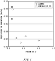
- Fig. 1 is a graph showing a relationship between a value of a parameter Q and a coefficient of variation for relative refractive index difference ⁇ of a fluorine added layer.
- a manufacturing method for an optical fiber base material includes a sintering process including a first step in which a porous glass stack is dehydrated using a chlorine-based gas, a second step in which fluorine is added, and a third step in which the glass is made transparent under a gas atmosphere containing a fluorine source, in order to obtain a fluorine-containing optical fiber base material.
- a value of the parameter Q is set to the range Q > 0.14 is that if Q is 0.14 or less, a coefficient of variation for the relative refractive index difference ⁇ of the fluorine added layer along its radial direction will exceed 0.03 and an optical fiber with fine optical characteristics cannot be obtained.
- a porous glass stack was first inserted in a furnace core tube and placed above a heater.
- the glass stack was heated to 1100 °C (1373K) and then Cl 2 as a chlorine-based gas was introduced along with an inert gas (He) into the furnace core tube.
- the porous glass stack was gradually moved downward from above the heater to dehydrate the porous glass stack from its lower end (the first step).
- the porous glass stack was again placed over the heater, the temperature was maintained at 1100 °C, and an inert gas (Fe) and a fluorine compound gas (SiF 4 ; 0.75%) was introduced into the furnace core tube.
- the porous glass stack was then gradually moved downward from above the heater to add fluorine therein (the second step).
- the fluorine compound gas was introduced also in the third step so that desorption and stripping of the fluorine added in the second step could be controlled even though the porous glass stack was subjected to the high temperature to obtain the transparent glass.
- a coefficient of variation (standard deviation/arithmetic average) for the relative refractive index difference ⁇ along the radial direction of the fluorine added layer in the porous glass stack was 0.011.
- the fluorine-source gas concentration C 2 in the second step may be higher than the fluorine-source gas concentration C 3 in the third step.
- the process temperature T 1 in the first step may be higher than the process temperature T 2 in the second step.
- Comparative Example 1 through 3 fluorine was added to the porous glass stack and the porous glass stack was made transparent in the same manner as the above Example 1 except for the sintering gas condition, in other words, a value of Q.
- Process conditions for each comparative example were shown in Table 2 below. In the comparative examples, values of Q were made smaller than the above examples, and consequently coefficients of variation for the relative refractive index difference ⁇ were above 0.03.
- Table 2 FIRST STEP SECOND STEP THIRD STEP PARAMETER Q COEFFICIENT OF VARIATION TEMP. TEMP. SiF4 CONC.
- the sintering condition can also be set such that the value of the parameter Q is 0.27 or above in order to manufacture a fluorine-containing optical fiber base material with a small variation in relative refractive index difference ⁇ along the radial direction of its fluorine added layer.
Landscapes
- Chemical & Material Sciences (AREA)
- Engineering & Computer Science (AREA)
- Chemical Kinetics & Catalysis (AREA)
- General Chemical & Material Sciences (AREA)
- Life Sciences & Earth Sciences (AREA)
- Geochemistry & Mineralogy (AREA)
- Materials Engineering (AREA)
- Organic Chemistry (AREA)
- Physics & Mathematics (AREA)
- Thermal Sciences (AREA)
- General Life Sciences & Earth Sciences (AREA)
- Manufacturing & Machinery (AREA)
- Manufacture, Treatment Of Glass Fibers (AREA)
- Glass Melting And Manufacturing (AREA)
- Glass Compositions (AREA)
Abstract
Description
- The present invention relates to a method of manufacturing a fluorine-containing optical fiber base material and a fluorine-containing optical fiber base material thereof. More specifically, the invention relates to a method of manufacturing a glass base material for an optical fiber in which fluorine is evenly added in its radial direction, in particular, to a method of manufacturing a fluorine-containing optical fiber base material in which variation in relative refractive index difference Δ in the radial direction of the base material can be reduced, and a fluorine-containing optical fiber base material thereof.
- Optical fibers have a cladding which surrounds an outer surface of a core of the optical fiber propagating light to prevent light leakage therefrom. The core portion has a higher refractive index than that of the cladding portion. Characteristics of optical fibers are defined by their refractive-index distributions. In order to obtain desired characteristics of an optical fiber, generally, germanium (Ge) which increases the refractive index or fluorine which lowers the refractive index are added to the optical fiber made of synthetic silica. One of techniques to add fluorine into optical fibers is performing a heat treatment under a fluorine compound gas atmosphere onto a porous glass stack which is formed by a VAD method or the like. After fluorine is added, the porous glass stack is further heated at a higher processing temperature in order to make the glass transparent, and then a fluorine-containing optical fiber base material is obtained.
- However, when the outside diameter of the porous glass stack is large and/or a target density of fluorine added in the porous glass stack is high, the fluorine which has been added in the previous process can be desorbed or stripped when it is subjected to a high temperature during the heating process for making the stack into a transparent glass. As a result, the optical fiber base material would have an unequal concentration along its radial direction.
- Therefore, it is an object of an aspect of the innovations herein to provide a method for manufacturing a fluorine-containing optical fiber base material in which fluorine can be added evenly along a radial direction and variation in relative refractive index difference Δ in the radial direction can be reduced, and to provide such fluorine-containing optical fiber base material, which are capable of overcoming the above drawbacks accompanying the related art.
- In a first aspect of the innovations, it is an object of the invention to provide a method of manufacturing a fluorine-containing optical fiber base material and a fluorine-containing optical fiber base material thereof, which are capable of overcoming the above drawbacks accompanying the related art. The above and other objects can be achieved by combinations described in the claims. In the first aspect of the innovations, provided is a method of manufacturing a fluorine-containing optical fiber base material through a sintering process. The sintering process includes a first step in which a porous glass stack is dehydrated by heating the porous glass stack under a chlorine-based gas atmosphere, a second step in which fluorine is added into the porous glass stack by heating the porous glass stack under a fluorine source gas atmosphere, and a third step in which the porous glass stack is made transparent by heating the porous glass stack at a higher temperature than the second step under a fluorine source gas atmosphere. Here, process temperatures in the first, second and third steps are T1, T2 and T3 (K) respectively, concentrations of the fluorine source gas in the second and third steps are C2 and C3 (%) respectively, a parameter Q is represented by the formula Q = C2×exp(-T2/T1) + C3×exp(-T2/T1), and the process temperatures and the concentrations of the fluorine source gas satisfy the relation Q > 0.14.
- In a second aspect of the innovations, the concentration C2 of the fluorine source gas in the second step may be equal to or above the concentration C3 of the fluorine source gas in the third step.
- In a third aspect of the innovations, the process temperature T1 in the first step may be equal to or above the process temperature T2 in the second step.
- In a fourth aspect of the innovations, a value of the parameter Q may be 0.27 or greater.
- A fifth aspect of the innovations may provide a fluorine-containing optical fiber base material manufactured by the above-described manufacturing method, and a coefficient of variation (standard deviation/arithmetic average) for relative refractive index difference Δ in a radial direction of a fluorine-added layer with respect to a level of quartz is 0.03 or smaller.
- The summary clause does not necessarily describe all necessary features of the embodiments of the present invention. The present invention may also be a sub-combination of the features described above.
-
Fig. 1 is a graph showing a relationship between a value of a parameter Q and a coefficient of variation for relative refractive index difference Δ of a fluorine added layer. - Hereinafter, some embodiments of the present invention will be described. The embodiments do not limit the invention according to the claims, and all the combinations of the features described in the embodiments are not necessarily essential to means provided by aspects of the invention.
- According to an aspect of the invention, a manufacturing method for an optical fiber base material includes a sintering process including a first step in which a porous glass stack is dehydrated using a chlorine-based gas, a second step in which fluorine is added, and a third step in which the glass is made transparent under a gas atmosphere containing a fluorine source, in order to obtain a fluorine-containing optical fiber base material. The fluorine-containing optical fiber base material is manufactured at process temperatures and fluorine-source gas concentrations with which a parameter Q in the formula Q = C2×exp(-T2/T1) + C3×exp(-T2/T1) satisfies Q > 0.14, where T1, T2 and T3 (K) are process temperatures for the first, second and third steps respectively, and C2 and C3 (%) are fluorine-source gas concentrations in the second and third steps respectively. The reason why a value of the parameter Q is set to the range Q > 0.14 is that if Q is 0.14 or less, a coefficient of variation for the relative refractive index difference Δ of the fluorine added layer along its radial direction will exceed 0.03 and an optical fiber with fine optical characteristics cannot be obtained.
- Although fluorine addition to a porous glass stack and a process to make the glass transparent according to the invention will be hereunder described in conjunction with examples and comparative examples, it should be understood that the present invention is not limited to such examples but various embodiments are possible.
- A porous glass stack was first inserted in a furnace core tube and placed above a heater. The glass stack was heated to 1100 °C (1373K) and then Cl2 as a chlorine-based gas was introduced along with an inert gas (He) into the furnace core tube. The porous glass stack was gradually moved downward from above the heater to dehydrate the porous glass stack from its lower end (the first step). The porous glass stack was again placed over the heater, the temperature was maintained at 1100 °C, and an inert gas (Fe) and a fluorine compound gas (SiF4; 0.75%) was introduced into the furnace core tube. The porous glass stack was then gradually moved downward from above the heater to add fluorine therein (the second step).
- Again the porous glass stack was placed above the heater, the temperature was raised to 1420 °C (1693K) at which the porous glass stack can be made transparent. An inert gas (He) and a fluorine compound gas (SiF4; 0.30%) were subsequently introduced into the furnace core tube, and the porous glass stack was then gradually moved downward from above the heater to make the glass stack transparent while adding fluorine therein (the third step). A value of Q which was calculated from the formula Q = C2×exp(-T2/T1) + C3×exp(-T2/T1) was 0.41 in this example. According to such method, the fluorine compound gas was introduced also in the third step so that desorption and stripping of the fluorine added in the second step could be controlled even though the porous glass stack was subjected to the high temperature to obtain the transparent glass. As a result, a coefficient of variation (standard deviation/arithmetic average) for the relative refractive index difference Δ along the radial direction of the fluorine added layer in the porous glass stack was 0.011.
- The process temperatures T1, T2 and T3 (K) in the first, second and third steps and the fluorine-source gas concentrations C2 and C3 (%) in the second and third steps were adequately set such that a value of Q calculated from the formula Q = C2×exp(-T2/T1) + C3×exp(-T2/T1) satisfies Q > 0.14. Fluorine was added to the porous glass stack and the porous glass stack was then made transparent in the same manner as the above Example 1 except for different values of Q. Process conditions for each example were shown in Table 1 below.
- The fluorine-source gas concentration C2 in the second step may be higher than the fluorine-source gas concentration C3 in the third step. The process temperature T1 in the first step may be higher than the process temperature T2 in the second step.
- Consequently, as shown in Table 1, a coefficient of variation for the relative refractive index difference Δ was below 0.03 in all of the examples.
[Table 1] FIRST STEP SECOND STEP THIRD STEP PARAMETER Q COEFFICIENT OF VARIATION TEMP. TEMP. SiF4 CONC. TEMP. SiF4 CONC. (K) (K) (%) (K) (%) (-) (-) EXAMPLE 1 1373 1373 0.75 1693 0.30 0.41 0.011 EXAMPLE 2 1373 1373 1.25 1693 1.25 1.02 0.017 EXAMPLE 3 1373 1373 1.25 1673 0.25 0.57 0.028 EXAMPLE 4 1373 1323 0.50 1693 0.20 0.27 0.023 - In Comparative Example 1 through 3, fluorine was added to the porous glass stack and the porous glass stack was made transparent in the same manner as the above Example 1 except for the sintering gas condition, in other words, a value of Q. Process conditions for each comparative example were shown in Table 2 below. In the comparative examples, values of Q were made smaller than the above examples, and consequently coefficients of variation for the relative refractive index difference Δ were above 0.03.
[Table 2] FIRST STEP SECOND STEP THIRD STEP PARAMETER Q COEFFICIENT OF VARIATION TEMP. TEMP. SiF4 CONC. TEMP. SiF4 CONC. (K) (K) (%) (K) (%) (-) (-) COMPARATIVE EXAMPLE 1 1373 1373 0.25 1693 0.10 0.14 0.098 COMPARATIVE EXAMPLE 2 1373 1373 0.25 1693 0.05 0.11 0.105 COMPARATIVE EXAMPLE 3 1373 1323 0.15 1673 0.15 0.12 0.074 -
Fig. 1 illustrates a relationship between the values of Q and the coefficients of variation for the relative refractive index difference Δ. As shown in the above results, it was demonstrated that a fluorine-containing optical fiber base material with a small variation in relative refractive index difference Δ along the radial direction of its fluorine added layer could be manufactured by introducing a fluorine compound gas into the furnace core tube in the step of making the glass stack transparent after the step of fluorine addition, and setting a sintering condition such that a value of Q represented by the formula Q = C2×exp(-T2/T1) + C3×exp(-T2/T1) satisfies Q > 0.14. - The sintering condition can also be set such that the value of the parameter Q is 0.27 or above in order to manufacture a fluorine-containing optical fiber base material with a small variation in relative refractive index difference Δ along the radial direction of its fluorine added layer.
- In this way, it is also possible to manufacture a fluorine-containing optical fiber with a small variation in relative refractive index difference Δ along the radial direction of its fluorine added layer.
- While the embodiments of the present invention have been described, the technical scope of the invention is not limited to the above described embodiments. It is apparent to persons skilled in the art that various alterations and improvements can be added to the above-described embodiments. It is also apparent from the scope of the claims that the embodiments added with such alterations or improvements can be included in the technical scope of the invention.
- The operations, procedures, steps, and stages of each process performed by an apparatus, system, program, and method shown in the claims, embodiments, or diagrams can be performed in any order as long as the order is not indicated by "prior to," "before," or the like and as long as the output from a previous process is not used in a later process. Even if the process flow is described using phrases such as "first" or "next" in the claims, embodiments, or diagrams, it does not necessarily mean that the process must be performed in this order.
- As described above, according to the embodiments of the invention, even when an outer diameter of the porous glass stack is large and/or a target fluorine adding concentration is high, it is possible to realize a manufacturing method for a fluorine-containing optical fiber base material with a very small variation coefficient (standard deviation/arithmetic average) for relative refractive index difference Δ along the radial direction of its fluorine added layer, and a fluorine-containing optical fiber base material thereof.
Claims (5)
- A method of manufacturing a fluorine-containing optical fiber base material through a sintering process, the sintering process comprising;
dehydrating a porous glass stack by heating the porous glass stack under a chlorine-based gas atmosphere;
adding fluorine into the porous glass stack by heating the porous glass stack under a fluorine source gas atmosphere; and
making the porous glass stack transparent by heating the porous glass stack under a fluorine source gas atmosphere at a higher temperature than a temperature at which the porous glass stack is heated in the adding, wherein
process temperatures in the dehydrating, adding and making are T1, T2 and T3 (K) respectively, concentrations of the fluorine source gas in the adding and making are C2 and C3 (%) respectively, a parameter Q is represented by the formula:
and the process temperatures and the concentrations of the fluorine source gas satisfy the relation Q > 0.14. - The method of manufacturing a fluorine-containing optical fiber base material according to Claim 1, wherein
the concentration C2 of the fluorine source gas in the adding is equal to or above the concentration C3 of the fluorine source gas in the making. - The method of manufacturing a fluorine-containing optical fiber base material according to Claim 1 or Claim 2, wherein
the process temperature T1 in the dehydrating is equal to or above the process temperature T2 in the adding. - The method of manufacturing a fluorine-containing optical fiber base material according to any one of Claims 1-3, wherein a value of the parameter Q is 0.27 or greater.
- A fluorine-containing optical fiber base material manufactured by the method according to Claim 1, wherein a coefficient of variation (standard deviation/arithmetic average) for relative refractive index difference Δ in a radial direction of a fluorine-added layer with respect to a level of quartz is 0.03 or smaller.
Applications Claiming Priority (1)
| Application Number | Priority Date | Filing Date | Title |
|---|---|---|---|
| JP2011052634A JP2012188314A (en) | 2011-03-10 | 2011-03-10 | Method of manufacturing fluorine-containing optical fiber base material and fluorine-containing optical fiber base material |
Publications (2)
| Publication Number | Publication Date |
|---|---|
| EP2497755A1 true EP2497755A1 (en) | 2012-09-12 |
| EP2497755B1 EP2497755B1 (en) | 2015-10-21 |
Family
ID=45814393
Family Applications (1)
| Application Number | Title | Priority Date | Filing Date |
|---|---|---|---|
| EP12158732.3A Not-in-force EP2497755B1 (en) | 2011-03-10 | 2012-03-09 | Method of manufacturing fluorine-containing optical fiber base material |
Country Status (4)
| Country | Link |
|---|---|
| US (1) | US20120231943A1 (en) |
| EP (1) | EP2497755B1 (en) |
| JP (1) | JP2012188314A (en) |
| CN (1) | CN102674682B (en) |
Families Citing this family (1)
| Publication number | Priority date | Publication date | Assignee | Title |
|---|---|---|---|---|
| JP7332559B2 (en) * | 2020-09-16 | 2023-08-23 | 信越化学工業株式会社 | Manufacturing method of glass base material for optical fiber |
Citations (7)
| Publication number | Priority date | Publication date | Assignee | Title |
|---|---|---|---|---|
| JPH01286932A (en) * | 1988-05-11 | 1989-11-17 | Fujikura Ltd | Production of optical fiber preform |
| US5306322A (en) * | 1989-06-29 | 1994-04-26 | Sumitomo Electric Industries, Ltd. | Process for thermal treatment of glass fiber preform |
| US20010043782A1 (en) * | 1997-01-16 | 2001-11-22 | Yoshio Yokoyama | Optical fiber and method of manufacturing the same |
| JP2002274876A (en) * | 2001-03-15 | 2002-09-25 | Sumitomo Electric Ind Ltd | Method for manufacturing glass articles |
| US20040151455A1 (en) * | 2000-08-28 | 2004-08-05 | Sumitomo Electric Industries, Ltd. | Optical fiber, method of making optical fiber preform, and method of making optical fiber |
| JP2004345902A (en) * | 2003-05-22 | 2004-12-09 | Fujikura Ltd | Method for producing quartz glass, quartz glass, optical parts and optical fiber |
| JP2011052634A (en) | 2009-09-03 | 2011-03-17 | Nippon Steel Corp | Hermetic electric compressor |
Family Cites Families (5)
| Publication number | Priority date | Publication date | Assignee | Title |
|---|---|---|---|---|
| JPS60260430A (en) * | 1984-06-04 | 1985-12-23 | Sumitomo Electric Ind Ltd | Manufacture of base material for optical fiber containing fluorine in clad part |
| KR900003449B1 (en) * | 1986-06-11 | 1990-05-19 | 스미도모덴기고오교오 가부시기가이샤 | Dispersion-shift fiber and its production |
| JPH0450130A (en) * | 1990-06-20 | 1992-02-19 | Sumitomo Electric Ind Ltd | Method for manufacturing optical fiber base material |
| JP2002114531A (en) * | 2000-08-04 | 2002-04-16 | Sumitomo Electric Ind Ltd | Fluorine added glass |
| JP2004269287A (en) * | 2003-03-06 | 2004-09-30 | Shinetsu Quartz Prod Co Ltd | Optical synthetic quartz glass member and method of manufacturing the same |
-
2011
- 2011-03-10 JP JP2011052634A patent/JP2012188314A/en not_active Withdrawn
-
2012
- 2012-03-08 CN CN201210058782.5A patent/CN102674682B/en not_active Expired - Fee Related
- 2012-03-08 US US13/414,731 patent/US20120231943A1/en not_active Abandoned
- 2012-03-09 EP EP12158732.3A patent/EP2497755B1/en not_active Not-in-force
Patent Citations (7)
| Publication number | Priority date | Publication date | Assignee | Title |
|---|---|---|---|---|
| JPH01286932A (en) * | 1988-05-11 | 1989-11-17 | Fujikura Ltd | Production of optical fiber preform |
| US5306322A (en) * | 1989-06-29 | 1994-04-26 | Sumitomo Electric Industries, Ltd. | Process for thermal treatment of glass fiber preform |
| US20010043782A1 (en) * | 1997-01-16 | 2001-11-22 | Yoshio Yokoyama | Optical fiber and method of manufacturing the same |
| US20040151455A1 (en) * | 2000-08-28 | 2004-08-05 | Sumitomo Electric Industries, Ltd. | Optical fiber, method of making optical fiber preform, and method of making optical fiber |
| JP2002274876A (en) * | 2001-03-15 | 2002-09-25 | Sumitomo Electric Ind Ltd | Method for manufacturing glass articles |
| JP2004345902A (en) * | 2003-05-22 | 2004-12-09 | Fujikura Ltd | Method for producing quartz glass, quartz glass, optical parts and optical fiber |
| JP2011052634A (en) | 2009-09-03 | 2011-03-17 | Nippon Steel Corp | Hermetic electric compressor |
Non-Patent Citations (1)
| Title |
|---|
| TANDON ET AL: "Doping of silica during sintering", JOURNAL OF NON-CRYSTALLINE SOLIDS, NORTH-HOLLAND PHYSICS PUBLISHING. AMSTERDAM, NL, vol. 351, no. 16-17, 1 June 2005 (2005-06-01), pages 1466 - 1472, XP027660835, ISSN: 0022-3093, [retrieved on 20050601] * |
Also Published As
| Publication number | Publication date |
|---|---|
| CN102674682A (en) | 2012-09-19 |
| CN102674682B (en) | 2014-08-13 |
| US20120231943A1 (en) | 2012-09-13 |
| EP2497755B1 (en) | 2015-10-21 |
| JP2012188314A (en) | 2012-10-04 |
Similar Documents
| Publication | Publication Date | Title |
|---|---|---|
| JP5394734B2 (en) | Cage made of quartz glass for processing semiconductor wafers and method of manufacturing the cage | |
| US10031282B2 (en) | Optical fiber | |
| EP1739063A2 (en) | Low loss optical fiber designs and methods for their manufacture | |
| Tomashuk et al. | Enhanced Radiation Resistance of Silica Optical Fibers Fabricated in High O Excess Conditions | |
| EP2479150A1 (en) | Optical fiber preform, optical fiber, and method of manufacturing optical fiber preform | |
| EP3041801B1 (en) | Method of making updoped cladding by using silicon tertrachloride as the dopant | |
| EP2692705B1 (en) | Method for manufacturing optical fiber base material | |
| CN105916823A (en) | Method for producing optical fiber preform and method for producing optical fiber | |
| CN1849270A (en) | Process for producing optical fiber preform, process for producing optical fiber and optical fiber | |
| CN108700704B (en) | Optical fiber | |
| JP2019505837A (en) | Bromine-doped optical fiber and method for producing the bromine-doped optical fiber | |
| JP2017526599A (en) | Method of making optical fiber in a reducing atmosphere | |
| US4812153A (en) | Method of making a glass body having a graded refractive index profile | |
| CN1284738C (en) | Treatment of soot preforms with reducing agents | |
| US6823125B2 (en) | Optical fiber base material, its manufacturing method and optical fiber | |
| EP2497755B1 (en) | Method of manufacturing fluorine-containing optical fiber base material | |
| GB2457946A (en) | Method of manufacturing a photonic bandgap fibre | |
| JP7044189B2 (en) | Synthetic quartz glass substrate | |
| JP5783712B2 (en) | Optical fiber preform manufacturing method and optical fiber manufacturing method | |
| KR890001124B1 (en) | Method for producing glass preform | |
| JP2010070432A (en) | Method for processing highly homogenous material | |
| JP2006030655A (en) | Optical fiber and its evaluation method and manufacturing method | |
| EP4371950B1 (en) | Optical fiber and manufacturing method therefor | |
| CN1330985C (en) | Method for reducing hydrogen sensitivity of optical fiber | |
| US8245542B2 (en) | Method for producing a cylinder from synthetic quartz glass |
Legal Events
| Date | Code | Title | Description |
|---|---|---|---|
| PUAI | Public reference made under article 153(3) epc to a published international application that has entered the european phase |
Free format text: ORIGINAL CODE: 0009012 |
|
| AK | Designated contracting states |
Kind code of ref document: A1 Designated state(s): AL AT BE BG CH CY CZ DE DK EE ES FI FR GB GR HR HU IE IS IT LI LT LU LV MC MK MT NL NO PL PT RO RS SE SI SK SM TR |
|
| AX | Request for extension of the european patent |
Extension state: BA ME |
|
| 17P | Request for examination filed |
Effective date: 20130311 |
|
| GRAP | Despatch of communication of intention to grant a patent |
Free format text: ORIGINAL CODE: EPIDOSNIGR1 |
|
| RIC1 | Information provided on ipc code assigned before grant |
Ipc: C03B 37/014 20060101AFI20150206BHEP |
|
| INTG | Intention to grant announced |
Effective date: 20150311 |
|
| GRAP | Despatch of communication of intention to grant a patent |
Free format text: ORIGINAL CODE: EPIDOSNIGR1 |
|
| INTG | Intention to grant announced |
Effective date: 20150518 |
|
| GRAP | Despatch of communication of intention to grant a patent |
Free format text: ORIGINAL CODE: EPIDOSNIGR1 |
|
| INTG | Intention to grant announced |
Effective date: 20150624 |
|
| GRAS | Grant fee paid |
Free format text: ORIGINAL CODE: EPIDOSNIGR3 |
|
| GRAA | (expected) grant |
Free format text: ORIGINAL CODE: 0009210 |
|
| AK | Designated contracting states |
Kind code of ref document: B1 Designated state(s): AL AT BE BG CH CY CZ DE DK EE ES FI FR GB GR HR HU IE IS IT LI LT LU LV MC MK MT NL NO PL PT RO RS SE SI SK SM TR |
|
| REG | Reference to a national code |
Ref country code: GB Ref legal event code: FG4D Ref country code: NL Ref legal event code: MP Effective date: 20151021 |
|
| REG | Reference to a national code |
Ref country code: CH Ref legal event code: EP |
|
| REG | Reference to a national code |
Ref country code: AT Ref legal event code: REF Ref document number: 756480 Country of ref document: AT Kind code of ref document: T Effective date: 20151115 |
|
| REG | Reference to a national code |
Ref country code: IE Ref legal event code: FG4D |
|
| REG | Reference to a national code |
Ref country code: DE Ref legal event code: R096 Ref document number: 602012011709 Country of ref document: DE |
|
| REG | Reference to a national code |
Ref country code: FR Ref legal event code: PLFP Year of fee payment: 5 |
|
| REG | Reference to a national code |
Ref country code: LT Ref legal event code: MG4D |
|
| REG | Reference to a national code |
Ref country code: AT Ref legal event code: MK05 Ref document number: 756480 Country of ref document: AT Kind code of ref document: T Effective date: 20151021 |
|
| PG25 | Lapsed in a contracting state [announced via postgrant information from national office to epo] |
Ref country code: HR Free format text: LAPSE BECAUSE OF FAILURE TO SUBMIT A TRANSLATION OF THE DESCRIPTION OR TO PAY THE FEE WITHIN THE PRESCRIBED TIME-LIMIT Effective date: 20151021 Ref country code: IS Free format text: LAPSE BECAUSE OF FAILURE TO SUBMIT A TRANSLATION OF THE DESCRIPTION OR TO PAY THE FEE WITHIN THE PRESCRIBED TIME-LIMIT Effective date: 20160221 Ref country code: NO Free format text: LAPSE BECAUSE OF FAILURE TO SUBMIT A TRANSLATION OF THE DESCRIPTION OR TO PAY THE FEE WITHIN THE PRESCRIBED TIME-LIMIT Effective date: 20160121 Ref country code: ES Free format text: LAPSE BECAUSE OF FAILURE TO SUBMIT A TRANSLATION OF THE DESCRIPTION OR TO PAY THE FEE WITHIN THE PRESCRIBED TIME-LIMIT Effective date: 20151021 Ref country code: NL Free format text: LAPSE BECAUSE OF FAILURE TO SUBMIT A TRANSLATION OF THE DESCRIPTION OR TO PAY THE FEE WITHIN THE PRESCRIBED TIME-LIMIT Effective date: 20151021 Ref country code: LT Free format text: LAPSE BECAUSE OF FAILURE TO SUBMIT A TRANSLATION OF THE DESCRIPTION OR TO PAY THE FEE WITHIN THE PRESCRIBED TIME-LIMIT Effective date: 20151021 Ref country code: IT Free format text: LAPSE BECAUSE OF FAILURE TO SUBMIT A TRANSLATION OF THE DESCRIPTION OR TO PAY THE FEE WITHIN THE PRESCRIBED TIME-LIMIT Effective date: 20151021 |
|
| PG25 | Lapsed in a contracting state [announced via postgrant information from national office to epo] |
Ref country code: SE Free format text: LAPSE BECAUSE OF FAILURE TO SUBMIT A TRANSLATION OF THE DESCRIPTION OR TO PAY THE FEE WITHIN THE PRESCRIBED TIME-LIMIT Effective date: 20151021 Ref country code: AT Free format text: LAPSE BECAUSE OF FAILURE TO SUBMIT A TRANSLATION OF THE DESCRIPTION OR TO PAY THE FEE WITHIN THE PRESCRIBED TIME-LIMIT Effective date: 20151021 Ref country code: PL Free format text: LAPSE BECAUSE OF FAILURE TO SUBMIT A TRANSLATION OF THE DESCRIPTION OR TO PAY THE FEE WITHIN THE PRESCRIBED TIME-LIMIT Effective date: 20151021 Ref country code: GR Free format text: LAPSE BECAUSE OF FAILURE TO SUBMIT A TRANSLATION OF THE DESCRIPTION OR TO PAY THE FEE WITHIN THE PRESCRIBED TIME-LIMIT Effective date: 20160122 Ref country code: PT Free format text: LAPSE BECAUSE OF FAILURE TO SUBMIT A TRANSLATION OF THE DESCRIPTION OR TO PAY THE FEE WITHIN THE PRESCRIBED TIME-LIMIT Effective date: 20160222 Ref country code: FI Free format text: LAPSE BECAUSE OF FAILURE TO SUBMIT A TRANSLATION OF THE DESCRIPTION OR TO PAY THE FEE WITHIN THE PRESCRIBED TIME-LIMIT Effective date: 20151021 Ref country code: RS Free format text: LAPSE BECAUSE OF FAILURE TO SUBMIT A TRANSLATION OF THE DESCRIPTION OR TO PAY THE FEE WITHIN THE PRESCRIBED TIME-LIMIT Effective date: 20151021 Ref country code: LV Free format text: LAPSE BECAUSE OF FAILURE TO SUBMIT A TRANSLATION OF THE DESCRIPTION OR TO PAY THE FEE WITHIN THE PRESCRIBED TIME-LIMIT Effective date: 20151021 |
|
| REG | Reference to a national code |
Ref country code: DE Ref legal event code: R097 Ref document number: 602012011709 Country of ref document: DE |
|
| PG25 | Lapsed in a contracting state [announced via postgrant information from national office to epo] |
Ref country code: CZ Free format text: LAPSE BECAUSE OF FAILURE TO SUBMIT A TRANSLATION OF THE DESCRIPTION OR TO PAY THE FEE WITHIN THE PRESCRIBED TIME-LIMIT Effective date: 20151021 |
|
| PLBE | No opposition filed within time limit |
Free format text: ORIGINAL CODE: 0009261 |
|
| STAA | Information on the status of an ep patent application or granted ep patent |
Free format text: STATUS: NO OPPOSITION FILED WITHIN TIME LIMIT |
|
| PG25 | Lapsed in a contracting state [announced via postgrant information from national office to epo] |
Ref country code: RO Free format text: LAPSE BECAUSE OF FAILURE TO SUBMIT A TRANSLATION OF THE DESCRIPTION OR TO PAY THE FEE WITHIN THE PRESCRIBED TIME-LIMIT Effective date: 20151021 Ref country code: BE Free format text: LAPSE BECAUSE OF NON-PAYMENT OF DUE FEES Effective date: 20160331 Ref country code: SM Free format text: LAPSE BECAUSE OF FAILURE TO SUBMIT A TRANSLATION OF THE DESCRIPTION OR TO PAY THE FEE WITHIN THE PRESCRIBED TIME-LIMIT Effective date: 20151021 Ref country code: DK Free format text: LAPSE BECAUSE OF FAILURE TO SUBMIT A TRANSLATION OF THE DESCRIPTION OR TO PAY THE FEE WITHIN THE PRESCRIBED TIME-LIMIT Effective date: 20151021 Ref country code: EE Free format text: LAPSE BECAUSE OF FAILURE TO SUBMIT A TRANSLATION OF THE DESCRIPTION OR TO PAY THE FEE WITHIN THE PRESCRIBED TIME-LIMIT Effective date: 20151021 Ref country code: SK Free format text: LAPSE BECAUSE OF FAILURE TO SUBMIT A TRANSLATION OF THE DESCRIPTION OR TO PAY THE FEE WITHIN THE PRESCRIBED TIME-LIMIT Effective date: 20151021 |
|
| 26N | No opposition filed |
Effective date: 20160722 |
|
| PG25 | Lapsed in a contracting state [announced via postgrant information from national office to epo] |
Ref country code: LU Free format text: LAPSE BECAUSE OF FAILURE TO SUBMIT A TRANSLATION OF THE DESCRIPTION OR TO PAY THE FEE WITHIN THE PRESCRIBED TIME-LIMIT Effective date: 20160309 Ref country code: MC Free format text: LAPSE BECAUSE OF FAILURE TO SUBMIT A TRANSLATION OF THE DESCRIPTION OR TO PAY THE FEE WITHIN THE PRESCRIBED TIME-LIMIT Effective date: 20151021 |
|
| REG | Reference to a national code |
Ref country code: CH Ref legal event code: PL |
|
| GBPC | Gb: european patent ceased through non-payment of renewal fee |
Effective date: 20160309 |
|
| PG25 | Lapsed in a contracting state [announced via postgrant information from national office to epo] |
Ref country code: SI Free format text: LAPSE BECAUSE OF FAILURE TO SUBMIT A TRANSLATION OF THE DESCRIPTION OR TO PAY THE FEE WITHIN THE PRESCRIBED TIME-LIMIT Effective date: 20151021 |
|
| REG | Reference to a national code |
Ref country code: IE Ref legal event code: MM4A |
|
| PG25 | Lapsed in a contracting state [announced via postgrant information from national office to epo] |
Ref country code: BE Free format text: LAPSE BECAUSE OF FAILURE TO SUBMIT A TRANSLATION OF THE DESCRIPTION OR TO PAY THE FEE WITHIN THE PRESCRIBED TIME-LIMIT Effective date: 20151021 |
|
| PG25 | Lapsed in a contracting state [announced via postgrant information from national office to epo] |
Ref country code: CH Free format text: LAPSE BECAUSE OF NON-PAYMENT OF DUE FEES Effective date: 20160331 Ref country code: LI Free format text: LAPSE BECAUSE OF NON-PAYMENT OF DUE FEES Effective date: 20160331 Ref country code: IE Free format text: LAPSE BECAUSE OF NON-PAYMENT OF DUE FEES Effective date: 20160309 Ref country code: GB Free format text: LAPSE BECAUSE OF NON-PAYMENT OF DUE FEES Effective date: 20160309 |
|
| REG | Reference to a national code |
Ref country code: FR Ref legal event code: PLFP Year of fee payment: 6 |
|
| PG25 | Lapsed in a contracting state [announced via postgrant information from national office to epo] |
Ref country code: MT Free format text: LAPSE BECAUSE OF FAILURE TO SUBMIT A TRANSLATION OF THE DESCRIPTION OR TO PAY THE FEE WITHIN THE PRESCRIBED TIME-LIMIT Effective date: 20151021 |
|
| REG | Reference to a national code |
Ref country code: FR Ref legal event code: PLFP Year of fee payment: 7 |
|
| PG25 | Lapsed in a contracting state [announced via postgrant information from national office to epo] |
Ref country code: CY Free format text: LAPSE BECAUSE OF FAILURE TO SUBMIT A TRANSLATION OF THE DESCRIPTION OR TO PAY THE FEE WITHIN THE PRESCRIBED TIME-LIMIT Effective date: 20151021 Ref country code: HU Free format text: LAPSE BECAUSE OF FAILURE TO SUBMIT A TRANSLATION OF THE DESCRIPTION OR TO PAY THE FEE WITHIN THE PRESCRIBED TIME-LIMIT; INVALID AB INITIO Effective date: 20120309 |
|
| PG25 | Lapsed in a contracting state [announced via postgrant information from national office to epo] |
Ref country code: MT Free format text: LAPSE BECAUSE OF FAILURE TO SUBMIT A TRANSLATION OF THE DESCRIPTION OR TO PAY THE FEE WITHIN THE PRESCRIBED TIME-LIMIT Effective date: 20160331 Ref country code: MK Free format text: LAPSE BECAUSE OF FAILURE TO SUBMIT A TRANSLATION OF THE DESCRIPTION OR TO PAY THE FEE WITHIN THE PRESCRIBED TIME-LIMIT Effective date: 20151021 Ref country code: TR Free format text: LAPSE BECAUSE OF FAILURE TO SUBMIT A TRANSLATION OF THE DESCRIPTION OR TO PAY THE FEE WITHIN THE PRESCRIBED TIME-LIMIT Effective date: 20151021 |
|
| PG25 | Lapsed in a contracting state [announced via postgrant information from national office to epo] |
Ref country code: BG Free format text: LAPSE BECAUSE OF FAILURE TO SUBMIT A TRANSLATION OF THE DESCRIPTION OR TO PAY THE FEE WITHIN THE PRESCRIBED TIME-LIMIT Effective date: 20151021 |
|
| PG25 | Lapsed in a contracting state [announced via postgrant information from national office to epo] |
Ref country code: AL Free format text: LAPSE BECAUSE OF FAILURE TO SUBMIT A TRANSLATION OF THE DESCRIPTION OR TO PAY THE FEE WITHIN THE PRESCRIBED TIME-LIMIT Effective date: 20151021 |
|
| PGFP | Annual fee paid to national office [announced via postgrant information from national office to epo] |
Ref country code: FR Payment date: 20230208 Year of fee payment: 12 |
|
| PGFP | Annual fee paid to national office [announced via postgrant information from national office to epo] |
Ref country code: DE Payment date: 20230131 Year of fee payment: 12 |
|
| REG | Reference to a national code |
Ref country code: DE Ref legal event code: R119 Ref document number: 602012011709 Country of ref document: DE |
|
| PG25 | Lapsed in a contracting state [announced via postgrant information from national office to epo] |
Ref country code: DE Free format text: LAPSE BECAUSE OF NON-PAYMENT OF DUE FEES Effective date: 20241001 |
|
| PG25 | Lapsed in a contracting state [announced via postgrant information from national office to epo] |
Ref country code: FR Free format text: LAPSE BECAUSE OF NON-PAYMENT OF DUE FEES Effective date: 20240331 |
|
| PG25 | Lapsed in a contracting state [announced via postgrant information from national office to epo] |
Ref country code: FR Free format text: LAPSE BECAUSE OF NON-PAYMENT OF DUE FEES Effective date: 20240331 Ref country code: DE Free format text: LAPSE BECAUSE OF NON-PAYMENT OF DUE FEES Effective date: 20241001 |