EP2497641A1 - Ink cleaning method and device for flexographic press - Google Patents
Ink cleaning method and device for flexographic press Download PDFInfo
- Publication number
- EP2497641A1 EP2497641A1 EP10828239A EP10828239A EP2497641A1 EP 2497641 A1 EP2497641 A1 EP 2497641A1 EP 10828239 A EP10828239 A EP 10828239A EP 10828239 A EP10828239 A EP 10828239A EP 2497641 A1 EP2497641 A1 EP 2497641A1
- Authority
- EP
- European Patent Office
- Prior art keywords
- ink
- cleaning
- multiphase fluid
- ink chamber
- printing machine
- Prior art date
- Legal status (The legal status is an assumption and is not a legal conclusion. Google has not performed a legal analysis and makes no representation as to the accuracy of the status listed.)
- Granted
Links
Images


Classifications
-
- B—PERFORMING OPERATIONS; TRANSPORTING
- B41—PRINTING; LINING MACHINES; TYPEWRITERS; STAMPS
- B41F—PRINTING MACHINES OR PRESSES
- B41F35/00—Cleaning arrangements or devices
- B41F35/04—Cleaning arrangements or devices for inking rollers
-
- B—PERFORMING OPERATIONS; TRANSPORTING
- B41—PRINTING; LINING MACHINES; TYPEWRITERS; STAMPS
- B41F—PRINTING MACHINES OR PRESSES
- B41F31/00—Inking arrangements or devices
- B41F31/02—Ducts, containers, supply or metering devices
- B41F31/027—Ink rail devices for inking ink rollers
-
- B—PERFORMING OPERATIONS; TRANSPORTING
- B41—PRINTING; LINING MACHINES; TYPEWRITERS; STAMPS
- B41F—PRINTING MACHINES OR PRESSES
- B41F31/00—Inking arrangements or devices
- B41F31/20—Ink-removing or collecting devices
-
- B—PERFORMING OPERATIONS; TRANSPORTING
- B41—PRINTING; LINING MACHINES; TYPEWRITERS; STAMPS
- B41F—PRINTING MACHINES OR PRESSES
- B41F35/00—Cleaning arrangements or devices
-
- B—PERFORMING OPERATIONS; TRANSPORTING
- B41—PRINTING; LINING MACHINES; TYPEWRITERS; STAMPS
- B41P—INDEXING SCHEME RELATING TO PRINTING, LINING MACHINES, TYPEWRITERS, AND TO STAMPS
- B41P2200/00—Printing processes
- B41P2200/10—Relief printing
- B41P2200/12—Flexographic printing
-
- B—PERFORMING OPERATIONS; TRANSPORTING
- B41—PRINTING; LINING MACHINES; TYPEWRITERS; STAMPS
- B41P—INDEXING SCHEME RELATING TO PRINTING, LINING MACHINES, TYPEWRITERS, AND TO STAMPS
- B41P2231/00—Inking devices; Recovering printing ink
- B41P2231/20—Recovering printing ink
-
- B—PERFORMING OPERATIONS; TRANSPORTING
- B41—PRINTING; LINING MACHINES; TYPEWRITERS; STAMPS
- B41P—INDEXING SCHEME RELATING TO PRINTING, LINING MACHINES, TYPEWRITERS, AND TO STAMPS
- B41P2235/00—Cleaning
- B41P2235/30—Recovering used solvents or residues
-
- B—PERFORMING OPERATIONS; TRANSPORTING
- B41—PRINTING; LINING MACHINES; TYPEWRITERS; STAMPS
- B41P—INDEXING SCHEME RELATING TO PRINTING, LINING MACHINES, TYPEWRITERS, AND TO STAMPS
- B41P2235/00—Cleaning
- B41P2235/50—Selection of materials or products for cleaning
Definitions
- the present invention relates a method of and a system for cleaning off an ink in a flexographic printing machine provided in a corrugated board box producing line, which improves the cleaning effect, reduces the time required for cleaning, as well as reducing the consumption of cleaning water, during ink cleaning.
- a box producing apparatus line for producing corrugated board sheet boxes from corrugated board sheets is provided with a paper supply section, a flexographic printing section, a slotting section for forming scorer lines, flaps, and joints, a perforating section, a folding section, and a joint bounding section, in this order, from the upstream.
- the flexographic printing section perform printing on corrugated board sheets wish flexographic inks using a flexographic printing machine.
- "flexographic printing” is one type of letterpress printing techniques.
- Flexographic printing is a printing technique using printing brocks, made from rubber or synthetics resins, and liquid inks (water-soluble inks and UV inks), and has been employed for surface printing on corrugated board sheets, films, and textiles. Decently, improvement s in the laser engraving and printing techniques tenable more-precise printing, and new demands for the flexographic printing is being created.
- Patent Reference 1 Japanese Laid-Open Patent Application H10-296961 discloses a procedure for changing inks in a flexographic printing machine.
- a flexographic printing machine and a procedure for changing inks in this flexographic printing machine, disclosed in Patent Reference 1, will be described with reference to FIGS. 11 and 12 .
- a flexographic printing machine 100 includes an ink supply device 102, an anilox roll 104, a printing die 106, a printing cylinder 108, and an impression cylinder (receiving roll) 110, for printing on a corrugated board sheet "c".
- the printing die 106 is wound about the outer peripheral face of the printing cylinder 108, and a flexographic ink (hereinafter, simply referred to as an ink) "f" is supplied from the ink supply device 102 to the outer peripheral face of the anilox roll 104.
- the anilox roll 104 rotates while contacting the printing die 106 to transfer the ink "f" to the surface of the print i ng die 106.
- the impression cylinder 110 is provided udder the printing cylinder 108 so as to face the printing cylinder 108.
- the corrugated board sheet "c" is inverted between the printing cylinder 108 and the impression cylinder 110 by means of rotation of the printing cylinder 108 and the impression cylinder 110, and the printing die 106 prints on the corrugated board sheet "c" .
- the ink supply device 102 is provided with an ink chamber 112 which is enclosed with a chamber frame 114 that defines the rear wall and the left and right walls, a seal blade 116 provided at the upper end of the chamber frame 114, a doctor blade 118 provided at the lower end of the chamber frame 114, and the anilox roll 104 that rotates while contacting the blades 116 and 118.
- the ink chamber 112 is formed along the long axis direction of the anilox roll 104 such that an ink "f" stored in the ink chamber 112 contacts the outer peripheral face of the anilox roll 104.
- air supply ports 120 are provided along the longitudinal direction of the chamber frame 114 at the top of the chamber frame 114 .
- An air supply branch pipe 124 branched from an air supply pipe 122 is connected to each air supply port 120.
- a solenoid valve 126 is interposed, and a compressed air supply device (not shown), such as a compressor, for supplying compressed air "a", is connected
- an ink supply port 128 is formed at the bottom of the center with respect to the longitudinal direction of the chamber frame 114, and an ink supply pipe 130 is connected to the ink supply port 128.
- An ink pump 132 and a solenoid valve 134 are interposed in the ink supple pipe 130, and the ink supply pipe 130 is connected to an ink contained 136.
- An ink recovery system for recovering the ink "f" in the ink chamber 112 to the ink container 136 is constructed from ink recovery pipes 142 connected to ink recovery ports 138 formed at the bottom ends of the chamber frame 114; excessive ink recovery pipes 144 connected to the excessive ink recovery ports 140 (for maintaining constant ink fluid level) formed at the upper ends of the chamber frame 114; solenoid valves 146 interposed in the ink recovery pipes 142 ; and an ink recovery pipe 148 connecting between the ink recovery pipes 142 and the excessive ink recovery pipes 144, and the ink container 136.
- a cleaning water supply pipe 152 is connected to the ink supply pipe 130 between the solenoid valves 134 and the ink pump 132, via a solenoid valve 150.
- the ink pump 132 is operated with the solenoid valve 150 being closed and the solenoid valve 134 being opened, to supply the ink "f" from the ink contained 136 through the ink supply port 128 into the ink chamber 112.
- the solenoid valves 146 are closed, and the ink "f” is maintained to a certain ink fluid level in the ink chamber 112, since any excessive ink overflows from the excessive ink recovery ports 140.
- the ink pump 132 is operated in the reverse direction to remover the ink "f" in the ink chamber 112 from the ink supply port 128 , as well as opening the solenoid valves 146.
- the solenoid valve 126 is opened to supply the compressed air "a” from the air supply pipe 122 into the ink chamber 112, thereby pressurizing the ink chamber 112.
- the ink "f" in the ink chamber 112 is forcefully collected from the ink supply pipe 130 and the ink recovery pipe 148 to the ink container 136.
- the solenoid valve 126 is closed to stop the supply of the compressed air "a".
- the ink container 136 is replaced with a waste fluid pit (not shown), and the solenoid valves 134 and 146 are closed. Subsequently, the solenoid valve 150 is opened, as well gas operating the ink pump 132 in the forward direction, to supply cleaning water "w" from the cleaning water supply pipe 152.
- the cleaning water "w” is supplied into the ink chamber 112 via the same path during the circulation of the ink "f” , and the ink chamber 112 is filled with the cleaning water "w”.
- the cleaning waster "w” is then collected from the excessive ink recovery ports 140 to the caste fluid pit, through the ink recovery pipe 148. This operation is repeated for a predetermined time duration to clean inside the ink circulation path.
- the solenoid valve 150 For collecting the cleaning water, the solenoid valve 150 is closed to stop the supply of the cleaning water "w”, and the solenoid valves 134 and 146 are opened. Subsequently, the ink pump 132 is operated in the reverse direction and the solenoid valve 126 is opened to supply the compressed air '"a" from the air supply pipe 122 into the ink chamber 112. As a result, the cleaning water "w” in the ink chamber 112 is drained out of the ink chamber 112 from the ink supply port 128 and the ink recovery ports 138, under the pressure by the compressed air "a” , and is forcefully collected into the caste fluid pit.
- the ink supply pipe 130 and the ink recovery pipe 148 are connected to an ink container 136 for a subsequent order.
- An subsequent order ink "f" is supplied two the ink chamber 112 through the ink supply pipe 130, for commencing printing of the subsequent order.
- an object of the present invention is to reduce the cleaning time and to reduce the consumption of cleaning water, by improving the cleaning effect during cleaning of an inside of the ink chamber of a flexographic printing machine. Furthermore, it is also an object to reduce the ink change time, including a cleaning step.
- a method of cleaning off an ink in a flexographic printing machine of the present invention is: a method of cleaning off an ink in a flexographic printing machine, wherein a flexographic ink is supplied to an ink chamber facing an outer peripheral face of an anilox roll, and the flexographic ink is transferred from the anilox roll to a printing die wound about a printing cylinder, the method includes: after removing the flexographic ink from the ink chamber, supplying a multiphase fluid to the ink chamber, to clean the ink chamber by means of a cleaning action of the multiphase fluid.
- the multiphase fluid is formed by mixing a gas or minute granular solids in two or more liquids or a liquid, in which the cleaning action is provided by suitably selecting the components to be mixed.
- the multiphase fluid is a cleaning liquid of water mixed with a cleaning agent, water or a cleaning liquid mixed with bubbles, or any other mixture of two or more liquids or gases having the cleaning action.
- the cleaning effect on the inside of the ink chamber is further enhanced by the agitating action and the turbulent flow generation action of the cleaning liquid containing the bubble. Since the cleaning effect on the outer peripheral face of the anilox roll and the inside of the ink chamber can be enhanced by means of the multiphase fluid, the cleaning time can be reduced and the consumption of the multiphase fluid can also be reduced.
- a circulation line for the multiphase fluid may be connected to the ink chamber to supply the multiphase fluid to the ink chamber through the circulation line in a circulatory manner.
- a system for cleaning off an ink in a flexographic printing machine of the present invention which can be directly used for the above-described method of the present invention, is: a system for cleaning off an ink in a flexographic printing machine, wherein a flexographic ink is supplied to an ink chamber facing an outer peripheral face of an anilox roll, and the flexographic ink is transferred from the anilox roll to a printing die wound about a printing cylinder, the system includes: a multiphase fluid supply path that supplies a multiphase fluid to an ink chamber; a multiphase fluid drain path that drains the multiphase fluid out of the ink chamber ; and a multiphase fluid generator that supplies the multiphase fluid to the multiphase fluid supply path, wherein the system is configured to supply the multiphase fluid to the ink chamber to clean an inside of the ink chamber bey means of a cleaning action of the multiphase fluid.
- the cleaning effect on the inside of the ink chamber can be improved with the cleaning action of the multiphase fluid.
- the cleaning time can be reduced and the consumption of the multiphase fluid can also be reduced.
- a supply circulatory passage may be connected to the multiphase fluid supply path and the multiphase fluid drain path, for supply the multiphase fluid to the ink chamber in a circulatory manner. Since this allows the multiphase fluid to be supplied into the ink chamber in a circulatory manner, the cleaning effect on the inside of the ink chamber can be further improved and the consumption of the multiphase fluid can be further reduced.
- a multiphase fluid generator may generate the cleaning liquid containing the bubbles at the multiphase fluid supply path by supplying the air to the cleaning liquid slowing through the multiphase fluid supply path.
- the multiphase fluid generator may be an air gun that forcefully injects the air into the multiphase fluid supply path or a device for taking the air into the multiphase fluid supply path by means of an ejector action. The air is taken into the cleaning liquid by employing the air sectioning action of the air gun or the ejector action, and the cleaning liquid containing bubbles is supplied to the ink chamber.
- the cleaning effect on the inside of the ink chamber can be enhanced by means of the agitating action and the turbulent flow generation action of the cleaning liquid containing bubbles and the energy of the high velocity flow of the cleaning liquid. Furthermore, infection of the bubbles into the cleaning liquid and the supply of the cleaning liquid to the ink chamber can be achieved only by a device utilizing an air gun or the ejector action, which can simplify the structure of the system and reduce the cost.
- a device for generating a pressure difference between two ends of the ink chamber in a longitudinal direction of the ink chamber may be provided, to generate a one-directional flow of the multiphase fluid in the longitudinal direction of the ink chamber by generating a pressure difference between the two ends of the ink chamber in the longitudinal direction.
- the device may be an air gun provided at feast one of upstream and downstream multiphase fluid supply paths with respect to the ink chamber.
- the air gun provided at the multiphase fluid supply path enables both the infection of bubbles into the multiphase fluid and the generation of the pressure difference, with a lower cost .
- the pressure gradient can be increased with the combined effect of the discharging action of the bubbles by the air gun provided at the upstream side and the suctioning action by the bubbles by the air gun provided at the downstream side, thereby improving the efficiency of the cleaning.
- a pressure reduction device may be provided at the multiphase fluid supply path, to induce a cavitation action in the cleaning liquid to generated bubbles, to supply the cleaning liquid containing bubbles to the ink chamber. This facilitates generation of the bubble-containing cleaning liquid, and the cleaning effect on the inside of the ink chamber can be enhanced by the agitating action resulted from collapse of the bubbles.
- a turbulent flow generator may be provided at the multiphase fluid supply path. This generates a turbulent flow in the cleaning water supplied to the ink chamber, thereby enhancing the cleaning effect.
- a control panel that displays a pressure ratio or a flow rate ratio between each fluid contained in the multiphase fluid may be provided. This allows the operator to appropriately control the pressure ratio or the flow rate ratio between each fluid contained in the multiphase fluid, while watching the control panel, to improve the cleaning effect on the inside of the ink chamber.
- the control panel provided to the flexographic printing machine facilitates control of the pressure ratio or the flow rate ratio between each fluid contained in the multiphase fluid.
- a method of cleaning of an ink in a flexographic printing machine wherein a flexographic ink is supplied to an ink chamber facing an outer peripheral face of an anilox roll, and the flexographic ink is transferred from the anilox roll to a printing die wound about a printing cylinder
- the method includes: after removing the flexographic ink from the ink chamber, supplying a multiphase fluid to the ink chamber, to clean the ink chamber by means of a cleaning action of the multiphase fluid.
- the system for cleaning of an ink in a flexographic printing machine wherein a flexographic ink is supplied to an ink chamber facing an outer peripheral face of an anilox roll, and the flexographic ink is transferred from the anilox roll to a printing die wound about a printing cylinder
- the system includes : a multiphase fluid supply path that supplies a multiphase fluid to an ink chamber; a multiphase fluid drain path that drains the multiphase fluid out of the ink chamber; and a multiphase fluid generator that supplies the multiphase fluid to the multiphase fluid supply path, wherein the system is configured to supply the multiphase fluid to the ink chamber to clean an inside of the ink chamber by means of a cleaning action of the multiphase fluid.
- FIGS. 1 and 2 show a portion of a flexographic printing machine 10 of this embodiment.
- a chamber frame 14 extends in the long axis direction of an anilox roll 12 so as to face the outer peripheral face of the anilox roll 12.
- the chamber frame 14 is provided with an ink chamber. 20 which is enclosed with a seal blade 16 that forms the rear wall and the left and right walls and is provided at the upper end of the chamber frame 14, a doctor blade 18 provided at the lower end of the chamber frame 14, and
- the anilox roll 12 that rotates while contacting the blades 16 and 18.
- the ink chamber 20 is formed along the axis direction of the anilox roll 12 such that a flexographic ink “f" (hereinafter, referred to as “ink “f") stored in the ink chamber 20 contacts the outer peripheral face of the anilox roll 12.
- An ink supply port 22 is formed at the bottom of the center with respect to the longitudinal direction of the chamber frame 14 , and an ink supply pipe 26 is connected to the ink supply port 22 via a three-way valve 24.
- An ink supply pump 28 is interposed in the ink supply pipe 26, and an end of the ink supply pump 28 is connected to an ink can 30.
- Excessive ink recovery ports 32 are formed at the upper ends of the chamber frame 14, and an ink recovery pipe 36 is connected to the excessive ink recovery port 32 via a three-way valve 34.
- An ink recovery pump 38 is interposed in the ink recovery pipe 36, and an end of the ink recovers pump 36 is connected to the ink can 30.
- the ink supply pipe 26 and the ink recovery pipe 36 are coupled to a connecting pipe 40 via the three-way valves 24 and 34, and an air gun 42 is interposed in the connecting pipe 40.
- the ink supply port 22 is selectively communicative to the ink supply pipe 26 or the connecting pipe 40 by means of the three-way valve 24, and the excessive ink recovery ports 32 are selectively communicative to the ink recovery pipe 36 or the connecting pipe 40 by means of the three-way valve 34.
- a circulatory piping line 44 is defined, which circulates through the ink supply pipe 26, the three-way valve 24, the ink supply port 22, the ink chamber 20, the excessive ink recovery ports 32, the three-way valve 34, and the connecting pipe 40.
- a pipe 46 for supplying cleaning water "w” or compressed air “a'” is also provided, and the pipe 46 is branched into two pipes 46a and 46b.
- the pipes 46a and 46b are respectively connected, near the ends of the chamber frame 14, to a header 41 provided in the longitudinal direction of the chamber frame 14.
- Multiple jetting ports 43 are formed in the header 41, through which the cleaning water "w” or the compressed air “a” supplied to the pipe 46 is distributed evenly within the ink chamber 20, along the longitudinal direction of the chamber frame 14.
- a supply pipe 48 which supplies dampening water “m” to the outer peripheral face of the anilox roll 12, is provided abode the seal blade 16. Solenoid valves 47 and 49 are provided at the pipes 46 and 48 for opening or cloying the pipes 46 and 48.
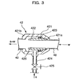
- a casing main body 421 of the air gun 42 is interposed in the connecting pipe 40, and includes a suctioning section 421a and an electing section 421b.
- a cylindrical passage defining member 422 is provided inside the casing main body 421 to define a passage 426 having a circular cross-section within the casing main body 421.
- An O-ring 423 is provided between the casing main body 421 and the passage defining member 422 for providing sealing.
- a compressed air supply pipe 424 is connected to the passage 426 via a solenoid valve 425. The compressed air supply pipe 424 is opened or closed by the solenoid valves 425.
- the cleaning water "w” may be pure water, or pure water mixed with some sort of a cleaning liquid or a cleaning agent.
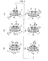
- FIGS . 4 and 5 show a printing operatic; using an ink prior to ink change.
- the ink supply pump 28 is operated to supply an ink "f" from the ink supply pipe 26 to the ink chamber 20 via the three-way valve 24 and the ink supply port 22.
- the ink recovery pump 38 is also operated to drain the ink "f” overflowing from the excessive ink recovery ports 32 to the ink recovery pipe 36 via the three-way valve 34.
- the flow of the ink is indicated with the arrow "b", and the flow of bubble-containing cleaning water (a + w), which will be described later, is indicated with the arrow "d".
- the three-way valves 24 and 34 are switched to connect the ink supply port 22 to the ink supply pipe 26 and to connect the excessive ink recovery ports 32 to the ink recovery pipe 36.
- Compressed air "a” is then supplied to the pipes 46a-b to pressurize inside the ink chamber 20, and the cleaning water “w” in the ink chamber 20 is collected to the waste fluid pit through the ink supply pipe 26 and the ink recovery pipe 36.
- the ink supply pipe 26 and the ink recovery pipe 36 define a cleaning water drain path.
- the cleaning water "w" can be quickly collected by rotating the ink supply pump 28 in the direction reverse to the rotation direction during the ink supply, as well as rotating the ink recovery pump 38 in the same direction as in the ink recovery.
- the circulatory passage 44 that supplies bubble-containing cleaning water (a + w) to the ink chamber 20 in a circulatory manner is defined, and compressed air "a" is supplied from the compressed air supply pipe 424 of the air gun 42.
- compressed air "a” is supplied from the compressed air supply pipe 424 of the air gun 42.
- the bubble-containing cleaning water (a + w) can be circulated to the ink chamber 20. Accordingly, the cleaning effect on the outer peripheral face of the anilox roll 12 and the inside of the ink chamber 20 can be improved by the agitating action and the turbulent flow generation action by the bubbles and a high velocity flow generated by the air gun 42.
- the cleaning effect can be obtained in a shorter time and the consumption of the cleaning water "w" can be significantly reduced.
- the amount of the ink supplied or recovered and the amount of the cleaning water "w” recovered can be increased, thereby significantly reducing the time required for these operations.
- the total time required for changing inks can be significantly reduced in this embodiment. For example, three minutes required for a conventional ink change procedure can be reduced to about two minutes, and accordingly, the machine stop time for set change is reduced. This can significantly improve the productivity of a box producing apparatus.
- FIGS. 6-8 a cleaning water supply port 54 is formed in an ink chamber 20, and a cleaning water supply pipe 50 is connected to the cleaning water supply port 54.
- An air gun 42 and a solenoid valve 52 are interposed in the cleaning water supply pipe 50.
- an air gun 56 is interposed in the ink recovery pipe 36, in place of the ink recovery pump 38 of the first embodiment.
- Other structures are same as those in the first embodiment.
- the air gun 56 has the same structure as that of the air gun 42 shown in FIG. 3 .
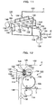
- FIG. 8(a) illustrates a printing operation with a previous order ink.
- the ink supply pump 28 is operated two supply the previous order ink "f" from the ink supply pipe 26 into the ink chamber 20, via the ink supply port 22.
- dampening water "m” is supplied from the pipe 48 to the anilox roll 12, as well as supplying compressed air '"a” from the pipes 46a-b into the ink chamber 20.
- the supplied compressed air “a” pressurizes inside the ink chamber 20, and the ink “f” in the ink chamber 20 is drained from the ink supply pipe 26 and the ink recovery pipe 36 to the ink can 30.
- the ink can be quickly collected, by rotating the ink supply pump 28 in the direction reverse to the rotation direction during the ink supply, and by supplying compressed air "a" two the compressed air supply pipe 561 connected to the air gun 56 two suction the ink "f" toward the ink can 30.
- the cleaning effect on the inside of the ink chamber 20 can be improved by means of the agitating action of the bubbles and a high velocity flow generated by the air gun 42. Accordingly, the cleaning time can be reduced, as well as reducing the consumption of the cleaning water "w". Furthermore, during ink recovery and recovery of cleaning water, the ink recovery time and the recover time for cleaning water can be reduced by rotating the ink supply pump 28 in the reverse direction, as well as operating the air gun 56. Thus, the total time required for ink cleaning or ink change can be significantly reduced. As a result, the production efficiency of a box producing apparatus can be improved.
- the cleaning and ink change steps in the flexographic printing machine 100 can be automated by providing a controller for controlling the solenoid valves, pumps, and the air guns; storing, in the controller, historical operation data of a box producing apparatus line and a flexographic printing machines 100; and providing a learning function or a function to select among operation modes.
- FIG. 9 is a schematic diagram of an ink chamber 60 viewed from the front, and components, such as an anilox roll 12, are omitted from the illustration.
- a cleaning water supply port 62 is provided at one end of the ink chamber 60, and a cleaning water drain port 64 is provided at the other end of the ink chamber 60.
- a cleaning water supply pipe 61 is connected to the cleaning water supply port 62, and a cleaning water drain pipe 63 is connected to the cleaning water supply port 62.
- An air gun 66 is interposed in the cleaning water supply port 62, and an air gun 68 is interposed in the cleaning water drain port 64.
- compressed air "a” is supplied to the air gun 66, thereby suctioning cleaning water “w” by means of the suction force of the compressed air "a”.
- the cleaning water (a + w) containing the air and the cleaning water mixed together, is supplied into the ink chamber 60, from the cleaning water supply port 62.
- the mixed cleaning water (a + w) flows to reach the cleaning water drain port 64, while cleaning off the ink "f” in the ink chamber 60.
- the mixed liquid of the mixed cleaning water (a + w) and the ink "f” reaching the cleaning water drain port 64 is drained from the cleaning water drain port 64 into the cleaning water drain pipe 63.
- Compressed air "b" supplied to the air gun 66 interposed in the cleaning water drain pipe 63 provides an ejection action, which causes the mixed liquid in the ink chamber 60 to be ejected into the cleaning water drain pipe 63.
- the mixed liquid which is the mixture of the compressed air (a + b) and the cleaning water "w”, and the ink “f” cleaned off from the ink chamber 60, is drained to the cleaning water drain pipe 63 downstream to the air gun 68.
- the pressure gradient inside the ink chamber 60 can be increased.
- a high velocity one-directional flow 65 of the mixed cleaning water (a + w) can be generated in the ink chamber 60.
- the ink cleaning effect on the inside of the ink chamber 60 can be improved.
- the efficiency of the cleaning can be improved.
- FIGS. 10(a) to 10(e) show carious exemplary configurations of bubble generators.
- FIG. 10 (a) shows a generator 70 including a cleaning water supply pipe 71 and an air supply pipe 72 connected to the cleaning water supply pipe 71, diagonally towards the direction of the flow of cleaning water "w".
- This generator 70 can take the air “a, from the outside, through the air supply pipe 72 by means of the ejector action which directs the cleaning water "w” to the cleaning water supply pipe 71 to the ink chamber.
- This configuration can generate dual-phase mixed flow (a + w) containing bubbles, which is supplied to the ink chamber.
- the structure can be simplified, which helps to reduce the cost.
- FIG. 10 (b) shows a disk-shaped contraction flow plate 74 having an orifice 73 at the center, within a cleaning water supply pipe 71.
- the contraction flow plate 74 When cleaning water "w" passes through the contraction flow plate 74, the flow is contracted by the orifice 73, which increases the flow velocity. This includes a pressure drop, which results in generation of bubbles by the cavitation action.
- the cleaning effect on the ink chamber can be improved by the agitating action resulted from collapse of the bubbles .
- FIG. 10 (d) is an example in which a contraction flow plate 77 having mesh pores 79 formed therein, in a ring body 78 defining an orifice, is provided at the passage in a cleaning water supply pipe 71.
- a contraction flow plate 77 By providing the contraction flow plate 77, bubbles are generated due to a pressure drop resulted from the orifice effect.
- the turbulent flow is generated when dual-phrase mixed flow (a + w) passes through the mesh pores 79.
- dual-phase mixed flow (a + w) exhibiting a higher cleaning effect, containing evenly distributed bubbles, is formed.
- FIG. 10 (e) is an example in which an axial flow pump 80 is provided within a cleaning water supply pipe 71.
- a cavitation action is induced on the surface of the fan to generate bubbles.
- This example is advantageous in that bubbles can be generated without inducing any undesirable pressure loss in the cleaning water supply pipe 71.
- the cleaning effect can be improved.
- change of inks can be performer in a shorter time, in a flexographic printing machine provided to a box producing apparatus.
- the production efficiency of the box producing apparatus can be improved, as well as improving the cleaning effect of an ink chamber and reducing the consumption of cleaning water.
Landscapes
- Inking, Control Or Cleaning Of Printing Machines (AREA)
Abstract
Description
- The present invention relates a method of and a system for cleaning off an ink in a flexographic printing machine provided in a corrugated board box producing line, which improves the cleaning effect, reduces the time required for cleaning, as well as reducing the consumption of cleaning water, during ink cleaning.
- A box producing apparatus line for producing corrugated board sheet boxes from corrugated board sheets is provided with a paper supply section, a flexographic printing section, a slotting section for forming scorer lines, flaps, and joints, a perforating section, a folding section, and a joint bounding section, in this order, from the upstream.
Among them, the flexographic printing section perform printing on corrugated board sheets wish flexographic inks using a flexographic printing machine.
As used herein, "flexographic printing" is one type of letterpress printing techniques. Flexographic printing is a printing technique using printing brocks, made from rubber or synthetics resins, and liquid inks (water-soluble inks and UV inks), and has been employed for surface printing on corrugated board sheets, films, and textiles. Decently, improvement s in the laser engraving and printing techniques tenable more-precise printing, and new demands for the flexographic printing is being created. - Patent Reference 1 (Japanese Laid-Open Patent Application
H10-296961 Patent Reference 1, will be described with reference toFIGS. 11 and 12 .
InFIGS. 11 and 12 , aflexographic printing machine 100 includes anink supply device 102, ananilox roll 104, a printing die 106, aprinting cylinder 108, and an impression cylinder (receiving roll) 110, for printing on a corrugated board sheet "c". - The printing die 106 is wound about the outer peripheral face of the
printing cylinder 108, and a flexographic ink (hereinafter, simply referred to as an ink) "f" is supplied from theink supply device 102 to the outer peripheral face of theanilox roll 104. Theanilox roll 104 rotates while contacting the printing die 106 to transfer the ink "f" to the surface of the printing die 106. Theimpression cylinder 110 is provided udder theprinting cylinder 108 so as to face theprinting cylinder 108. The corrugated board sheet "c" is inverted between theprinting cylinder 108 and theimpression cylinder 110 by means of rotation of theprinting cylinder 108 and theimpression cylinder 110, and the printing die 106 prints on the corrugated board sheet "c" . - The
ink supply device 102 is provided with anink chamber 112 which is enclosed with achamber frame 114 that defines the rear wall and the left and right walls, aseal blade 116 provided at the upper end of thechamber frame 114, adoctor blade 118 provided at the lower end of thechamber frame 114, and theanilox roll 104 that rotates while contacting theblades ink chamber 112 is formed along the long axis direction of theanilox roll 104 such that an ink "f" stored in theink chamber 112 contacts the outer peripheral face of theanilox roll 104. - Multiple (four, in
FIG. 11 )air supply ports 120 are provided along the longitudinal direction of thechamber frame 114 at the top of thechamber frame 114 . An airsupply branch pipe 124 branched from anair supply pipe 122 is connected to eachair supply port 120. In theair supply pipe 122, asolenoid valve 126 is interposed, and a compressed air supply device (not shown), such as a compressor, for supplying compressed air "a", is connected
Furthermore, anink supply port 128 is formed at the bottom of the center with respect to the longitudinal direction of thechamber frame 114, and anink supply pipe 130 is connected to theink supply port 128. Anink pump 132 and asolenoid valve 134 are interposed in theink supple pipe 130, and theink supply pipe 130 is connected to an ink contained 136. - An ink recovery system for recovering the ink "f" in the
ink chamber 112 to theink container 136 is constructed fromink recovery pipes 142 connected toink recovery ports 138 formed at the bottom ends of thechamber frame 114; excessiveink recovery pipes 144 connected to the excessive ink recovery ports 140 (for maintaining constant ink fluid level) formed at the upper ends of thechamber frame 114;solenoid valves 146 interposed in theink recovery pipes 142 ; and anink recovery pipe 148 connecting between theink recovery pipes 142 and the excessiveink recovery pipes 144, and theink container 136.
A cleaningwater supply pipe 152 is connected to theink supply pipe 130 between thesolenoid valves 134 and theink pump 132, via asolenoid valve 150. - In this configuration, during normal printing operations, the
ink pump 132 is operated with thesolenoid valve 150 being closed and thesolenoid valve 134 being opened, to supply the ink "f" from the ink contained 136 through theink supply port 128 into theink chamber 112. At this time, thesolenoid valves 146 are closed, and the ink "f" is maintained to a certain ink fluid level in theink chamber 112, since any excessive ink overflows from the excessiveink recovery ports 140. - For changing inks, the
ink pump 132 is operated in the reverse direction to remover the ink "f" in theink chamber 112 from theink supply port 128 , as well as opening thesolenoid valves 146. Subsequently, thesolenoid valve 126 is opened to supply the compressed air "a" from theair supply pipe 122 into theink chamber 112, thereby pressurizing theink chamber 112. As a result, the ink "f" in theink chamber 112 is forcefully collected from theink supply pipe 130 and theink recovery pipe 148 to theink container 136. After a predetermined time duration, thesolenoid valve 126 is closed to stop the supply of the compressed air "a". - For ink cleaning, the
ink container 136 is replaced with a waste fluid pit (not shown), and thesolenoid valves solenoid valve 150 is opened, as well gas operating theink pump 132 in the forward direction, to supply cleaning water "w" from the cleaningwater supply pipe 152. The cleaning water "w" is supplied into theink chamber 112 via the same path during the circulation of the ink "f" , and theink chamber 112 is filled with the cleaning water "w". The cleaning waster "w" is then collected from the excessiveink recovery ports 140 to the caste fluid pit, through theink recovery pipe 148. This operation is repeated for a predetermined time duration to clean inside the ink circulation path. - For collecting the cleaning water, the
solenoid valve 150 is closed to stop the supply of the cleaning water "w", and thesolenoid valves ink pump 132 is operated in the reverse direction and thesolenoid valve 126 is opened to supply the compressed air '"a" from theair supply pipe 122 into theink chamber 112. As a result, the cleaning water "w" in theink chamber 112 is drained out of theink chamber 112 from theink supply port 128 and theink recovery ports 138, under the pressure by the compressed air "a" , and is forcefully collected into the caste fluid pit. - Subsequently, the
ink supply pipe 130 and theink recovery pipe 148 are connected to anink container 136 for a subsequent order. An subsequent order ink "f" is supplied two theink chamber 112 through theink supply pipe 130, for commencing printing of the subsequent order. -
- Patent Reference 1: Japanese Laid-Open Patent Application No.
H10-296961 - In the method for changing inks disclosed in
Patent Reference 1, after supplying cleaning water "w" to theink chamber 112 through the cleaningwater supply pipe 152, the inside of theink chamber 112 is cleaned, while collecting the cleaning water "w" through theink supply pipe 130 and theink recovery pipe 148. Thus, cleaning water "w" is drained after the cleaning water "w" is lowed through theink chamber 112 once. Accordingly, there are issues of a lower cleaning effect relative to the consumption of the cleaning water, as well as a longer cleaning time and an increased consumption of the cleaning water "w". - in light of the issues of the above-described related art, an object of the present invention is to reduce the cleaning time and to reduce the consumption of cleaning water, by improving the cleaning effect during cleaning of an inside of the ink chamber of a flexographic printing machine. Furthermore, it is also an object to reduce the ink change time, including a cleaning step.
- To accomplish the above-identified objects, a method of cleaning off an ink in a flexographic printing machine of the present invention is: a method of cleaning off an ink in a flexographic printing machine, wherein a flexographic ink is supplied to an ink chamber facing an outer peripheral face of an anilox roll, and the flexographic ink is transferred from the anilox roll to a printing die wound about a printing cylinder, the method includes: after removing the flexographic ink from the ink chamber, supplying a multiphase fluid to the ink chamber, to clean the ink chamber by means of a cleaning action of the multiphase fluid.
- In the method of the present invention, the multiphase fluid is formed by mixing a gas or minute granular solids in two or more liquids or a liquid, in which the cleaning action is provided by suitably selecting the components to be mixed. Forexample, the multiphase fluid is a cleaning liquid of water mixed with a cleaning agent, water or a cleaning liquid mixed with bubbles, or any other mixture of two or more liquids or gases having the cleaning action.
When water containing bubbles or a cleaning liquid is supplied into the ink chamber, the cleaning effect on the inside of the ink chamber is further enhanced by the agitating action and the turbulent flow generation action of the cleaning liquid containing the bubble.
Since the cleaning effect on the outer peripheral face of the anilox roll and the inside of the ink chamber can be enhanced by means of the multiphase fluid, the cleaning time can be reduced and the consumption of the multiphase fluid can also be reduced. - In the method of the present invention, a circulation line for the multiphase fluid may be connected to the ink chamber to supply the multiphase fluid to the ink chamber through the circulation line in a circulatory manner.
By supplying the multiphase fluid to the ink chamber in a circulatory manner, the cleaning effect can be further improved and the consumption of the multiphase fluid can also be further reduced, since the multiphase fluid is cycled in a circulatory manner. - Experimental results by the present inventors et al. found that the cleaning effect on the inside of the ink chamber can be improved by providing a one-directional flow of a multiphase fluid in the longitudinal direction in the ink chamber. In the method of the present invention, a one-directional flow (either the direction from the driven side to the operating side, or the direction from the operating side to the driven side) of the multiphase fluid may be generated in a longitudinal direction of the ink chamber inside the ink chamber.
- The experimental results by the present inventors et al. also found that a pressure ratio or a flow rate ratio between each fluid contained in the multiphase fluid is related to the cleaning effect. Therefore, pressure ratio or a flow rate ratio between each fluid contained in the multiphase fluid may be controlled to improve an cleaning effect on the inside of the ink chamber.
- Furthermore, a system for cleaning off an ink in a flexographic printing machine of the present invention which can be directly used for the above-described method of the present invention, is: a system for cleaning off an ink in a flexographic printing machine, wherein a flexographic ink is supplied to an ink chamber facing an outer peripheral face of an anilox roll, and the flexographic ink is transferred from the anilox roll to a printing die wound about a printing cylinder, the system includes: a multiphase fluid supply path that supplies a multiphase fluid to an ink chamber; a multiphase fluid drain path that drains the multiphase fluid out of the ink chamber ; and a multiphase fluid generator that supplies the multiphase fluid to the multiphase fluid supply path, wherein the system is configured to supply the multiphase fluid to the ink chamber to clean an inside of the ink chamber bey means of a cleaning action of the multiphase fluid.
- Since the outer peripheral face of the anilox roll and the inside of the ink chamber can be cleaned with the multiphase fluid in the above-described configuration, the cleaning effect on the inside of the ink chamber can be improved with the cleaning action of the multiphase fluid. As a result, the cleaning time can be reduced and the consumption of the multiphase fluid can also be reduced.
- In the system of the present invention, a supply circulatory passage may be connected to the multiphase fluid supply path and the multiphase fluid drain path, for supply the multiphase fluid to the ink chamber in a circulatory manner. Since this allows the multiphase fluid to be supplied into the ink chamber in a circulatory manner, the cleaning effect on the inside of the ink chamber can be further improved and the consumption of the multiphase fluid can be further reduced.
- In the system of the present invention, if the multiphase fluid is a cleaning liquid containing bubbles, a multiphase fluid generator may generate the cleaning liquid containing the bubbles at the multiphase fluid supply path by supplying the air to the cleaning liquid slowing through the multiphase fluid supply path.
For example, the multiphase fluid generator may be an air gun that forcefully injects the air into the multiphase fluid supply path or a device for taking the air into the multiphase fluid supply path by means of an ejector action. The air is taken into the cleaning liquid by employing the air sectioning action of the air gun or the ejector action, and the cleaning liquid containing bubbles is supplied to the ink chamber. - By employing the air suctioning action of the air gun or the ejector action, the cleaning effect on the inside of the ink chamber can be enhanced by means of the agitating action and the turbulent flow generation action of the cleaning liquid containing bubbles and the energy of the high velocity flow of the cleaning liquid. Furthermore, infection of the bubbles into the cleaning liquid and the supply of the cleaning liquid to the ink chamber can be achieved only by a device utilizing an air gun or the ejector action, which can simplify the structure of the system and reduce the cost.
- In the system of the present invention, a device for generating a pressure difference between two ends of the ink chamber in a longitudinal direction of the ink chamber may be provided, to generate a one-directional flow of the multiphase fluid in the longitudinal direction of the ink chamber by generating a pressure difference between the two ends of the ink chamber in the longitudinal direction. As described above, by generating the pressure difference between the ends of the longitudinal direction of the ink chamber to generate a one-directional flow of the multiphase fluid in the longitudinal direction of the ink chamber, the cleaning effect on the inside of the ink chamber can be improved. The greater the pressure difference is, the higher the flow velocity of the multiphase fluid becomes, which further enhances the cleaning effect.
- The device may be an air gun provided at feast one of upstream and downstream multiphase fluid supply paths with respect to the ink chamber. The air gun provided at the multiphase fluid supply path enables both the infection of bubbles into the multiphase fluid and the generation of the pressure difference, with a lower cost . By providing air guns at the upstream and downstream sides to the ink chamber, the pressure gradient can be increased with the combined effect of the discharging action of the bubbles by the air gun provided at the upstream side and the suctioning action by the bubbles by the air gun provided at the downstream side, thereby improving the efficiency of the cleaning.
- In the system of the present invention, a pressure reduction device may be provided at the multiphase fluid supply path, to induce a cavitation action in the cleaning liquid to generated bubbles, to supply the cleaning liquid containing bubbles to the ink chamber. This facilitates generation of the bubble-containing cleaning liquid, and the cleaning effect on the inside of the ink chamber can be enhanced by the agitating action resulted from collapse of the bubbles.
- Furthermore, in the system of the present invention, a turbulent flow generator may be provided at the multiphase fluid supply path. This generates a turbulent flow in the cleaning water supplied to the ink chamber, thereby enhancing the cleaning effect.
- Furthermore, in the system of the present invention, a control panel that displays a pressure ratio or a flow rate ratio between each fluid contained in the multiphase fluid may be provided. This allows the operator to appropriately control the pressure ratio or the flow rate ratio between each fluid contained in the multiphase fluid, while watching the control panel, to improve the cleaning effect on the inside of the ink chamber. The control panel provided to the flexographic printing machine facilitates control of the pressure ratio or the flow rate ratio between each fluid contained in the multiphase fluid.
- In accordance with the method of the present invention, a method of cleaning of an ink in a flexographic printing machine, wherein a flexographic ink is supplied to an ink chamber facing an outer peripheral face of an anilox roll, and the flexographic ink is transferred from the anilox roll to a printing die wound about a printing cylinder, the method includes: after removing the flexographic ink from the ink chamber, supplying a multiphase fluid to the ink chamber, to clean the ink chamber by means of a cleaning action of the multiphase fluid. Hence, since the cleaning effect on the outer peripheral face of the anilox roll and the inside of the ink chamber can be enhanced, the cleaning time can be reduced and the consumption of the multiphase fluid can also be reduced.
- Furthermore, in accordance with the system of the present invention, the system for cleaning of an ink in a flexographic printing machine, wherein a flexographic ink is supplied to an ink chamber facing an outer peripheral face of an anilox roll, and the flexographic ink is transferred from the anilox roll to a printing die wound about a printing cylinder, the system includes : a multiphase fluid supply path that supplies a multiphase fluid to an ink chamber; a multiphase fluid drain path that drains the multiphase fluid out of the ink chamber; and a multiphase fluid generator that supplies the multiphase fluid to the multiphase fluid supply path, wherein the system is configured to supply the multiphase fluid to the ink chamber to clean an inside of the ink chamber by means of a cleaning action of the multiphase fluid. Hence, the effects similar to those of the above-described method of the present invention can be obtained.
-
-
FIG. 1 is a perspective view schematically illustrating a flexographic printing machine according to a first embodiment of a method and a system of the present invention; -
FIG. 2 is a side cross-sectional view schematically illustrating the flexographic printing machine; -
FIG. 3 is a cross-sectional view of anair gun 42 used in the flexographic printing machine; -
FIG. 4 is a perspective view schematically illustrating an ink change procedure in the flexographic printing machine; -
FIG. 5 is a side cross-sectional view schematically illustrating an ink change procedure in the flexographic printing machine; -
FIG. 6 is a perspective vies schematically illustrating a flexographic printing machine according to a second embodiment of a method and a system of the present invention; -
FIG. 7 is a side cross-sectional view schematically illustrating the flexographic printing machine of the second embodiment; -
FIG. 8 is a side cross-sectional view schematically illustrating an ink change procedure of the second embodiment,; -
Fig. 9 is a schematic diagram illustrating a third embodiment of a method and a system of the present invention ; -
FIGS. 10 is an illustrative diagram illustrating various exemplary configurations of bubble generators used in the method and the system of the present invention; -
FIG. 11 is a perspective view schematically illustrating a conventional system for cleaning off an ink in a flexographic printing machine; and -
FIG. 12 is a side cross-sectional view schematically illustrating the system for cleaning off an ink in the flexographic printing machine inFig. 11 . - Hereinafter, the present invention will be described with reference to embodiments of the present invention shown inthedrawings. Unless otherwise stated, it is not intended that the sizes, materials, shapes, relative positions, and the like of components described in the embodiments do not limit the scope of the present invention to these specifics .
- A first embodiment of a method and a system of the present invention will be described with reference to
FIGS. 1-5 .FIGS . 1 and 2 show a portion of aflexographic printing machine 10 of this embodiment. InFIGS. 1 and 2 , achamber frame 14 extends in the long axis direction of ananilox roll 12 so as to face the outer peripheral face of theanilox roll 12. Thechamber frame 14 is provided with an ink chamber. 20 which is enclosed with aseal blade 16 that forms the rear wall and the left and right walls and is provided at the upper end of thechamber frame 14, adoctor blade 18 provided at the lower end of thechamber frame 14, and The anilox roll 12 that rotates while contacting theblades - The
ink chamber 20 is formed along the axis direction of the anilox roll 12 such that a flexographic ink "f" (hereinafter, referred to as "ink "f") stored in theink chamber 20 contacts the outer peripheral face of theanilox roll 12. Anink supply port 22 is formed at the bottom of the center with respect to the longitudinal direction of thechamber frame 14 , and anink supply pipe 26 is connected to theink supply port 22 via a three-way valve 24. Anink supply pump 28 is interposed in theink supply pipe 26, and an end of theink supply pump 28 is connected to anink can 30. - Excessive
ink recovery ports 32 are formed at the upper ends of thechamber frame 14, and anink recovery pipe 36 is connected to the excessiveink recovery port 32 via a three-way valve 34. Anink recovery pump 38 is interposed in theink recovery pipe 36, and an end of the ink recoverspump 36 is connected to the ink can 30. Theink supply pipe 26 and theink recovery pipe 36 are coupled to a connectingpipe 40 via the three-way valves air gun 42 is interposed in the connectingpipe 40. - If
Fig. 1 , theink supply port 22 is selectively communicative to theink supply pipe 26 or the connectingpipe 40 by means of the three-way valve 24, and the excessiveink recovery ports 32 are selectively communicative to theink recovery pipe 36 or the connectingpipe 40 by means of the three-way valve 34.
In this manner, by operating the three-way valves circulatory piping line 44 is defined, which circulates through theink supply pipe 26, the three-way valve 24, theink supply port 22, theink chamber 20, the excessiveink recovery ports 32, the three-way valve 34, and the connectingpipe 40. - Furthermore, a
pipe 46 for supplying cleaning water "w" or compressed air "a'" is also provided, and thepipe 46 is branched into twopipes pipes chamber frame 14, to aheader 41 provided in the longitudinal direction of thechamber frame 14.
Multiple jetting ports 43 (seeFIG. 2 ) are formed in theheader 41, through which the cleaning water "w" or the compressed air "a" supplied to thepipe 46 is distributed evenly within theink chamber 20, along the longitudinal direction of thechamber frame 14. Furthermore, asupply pipe 48, which supplies dampening water "m" to the outer peripheral face of theanilox roll 12, is provided abode theseal blade 16.Solenoid valves pipes pipes - Next , the structure of the
air gun 42 will he described with reference toFIG. 3 . InFIG. 3 , a casingmain body 421 of theair gun 42 is interposed in the connectingpipe 40, and includes asuctioning section 421a and an electingsection 421b. A cylindricalpassage defining member 422 is provided inside the casingmain body 421 to define apassage 426 having a circular cross-section within the casingmain body 421. An O-ring 423 is provided between the casingmain body 421 and thepassage defining member 422 for providing sealing. A compressedair supply pipe 424 is connected to thepassage 426 via asolenoid valve 425. The compressedair supply pipe 424 is opened or closed by thesolenoid valves 425. - when the
solenoid valve 425 is opened to open the compressedair supply pipe 424, compressed air "a" flows between the casingmain body 421 and thepassage defining member 422 is jetted to thepassage 426. The jetting of the compressed air "a" provides the cleaning water "w" with auction force directed from the suctioning section, 421a toward theejecting section 421b. This results in mixing of the compressed air "a" and the cleaning water "w" inside thepassage 426, and the cleaning water containing bubbles (a + w) is jetted from the ejectingsection 421b.
In this embodiment, the cleaning water "w" may be pure water, or pure water mixed with some sort of a cleaning liquid or a cleaning agent. - The procedure for changing inks in the above stricture will be described with reference to
FIGS . 4 and5 . InFIGS . 4 and5 ,Fig. 4 (a) andFIG. 5 (a) show a printing operatic; using an ink prior to ink change. In the drawings, theink supply pump 28 is operated to supply an ink "f" from theink supply pipe 26 to theink chamber 20 via the three-way valve 24 and theink supply port 22. Theink recovery pump 38 is also operated to drain the ink "f" overflowing from the excessiveink recovery ports 32 to theink recovery pipe 36 via the three-way valve 34. InFIG. 2 , the flow of the ink is indicated with the arrow "b", and the flow of bubble-containing cleaning water (a + w), which will be described later, is indicated with the arrow "d". - in
FIG. 4(b) andFIG. 5(b) , the printing with the precious order ink is stopped. Dampening water "m" is supplied to the anilox roll 12 from thepipe 48, and purging compressed air "a" is supplied, from thepipes 46a-b to theheader 41, and then to the jettingports 43, into theink chamber 20. The compressed air "a" pressurizes inside theink chamber 20, which results in the ink "f" being collected from theink supply pipe 26 and theink recovery pipe 36.
In this step, the ink can be quickly collected by rotating theink supply pump 28 in the direction reverse to the rotation direction during the ink supply, as well as rotating theink recovery pump 38 in the same direction as in the ink recovery. - After the previous order ink "f" is being collected, the ink can 30 is replaced with a waste fluid pit (not shown). Subsequently, as shown in
FIG. 4 (c) andFIG. 5 (c) , cleaning water "w" is supplied to thepipes 46a-b while continuing the supply of the dampening water "m" to thepipe 48, to fill theink chamber 20 with the cleaning water "w". - Subsequently, as shown in
FIG. 4 (d) andFIG. 5 (d) , the three-way valves circulatory passage 44. Then, compressed air "a" is supplied from the compressedair supply pipe 424 of theair gun 42 into the cleaning water "w", to generate bubbles in the cleaning water "w" and to forcefully circulate the bubble-containing cleaning water (a + w) through thecirculatory passage 44 by means of the auctioning action of the compressed air "a". A source for compressed air in a factory may be used for supplying the compressed air "a", and compressed air "a" of 0.6 MPa or below is typically used. - Subsequently, as shown in
FIG. 4(e) andFIG. 5(e) , the three-way valves ink supply port 22 to theink supply pipe 26 and to connect the excessiveink recovery ports 32 to theink recovery pipe 36. Compressed air "a" is then supplied to thepipes 46a-b to pressurize inside theink chamber 20, and the cleaning water "w" in theink chamber 20 is collected to the waste fluid pit through theink supply pipe 26 and theink recovery pipe 36. In other words, theink supply pipe 26 and theink recovery pipe 36 define a cleaning water drain path.
In this step, in the manner similar to the ink recovery, the cleaning water "w" can be quickly collected by rotating theink supply pump 28 in the direction reverse to the rotation direction during the ink supply, as well as rotating theink recovery pump 38 in the same direction as in the ink recovery. - The cleaning and cleaning water recovery steeps from
FIG. 4(c) to FIG. 4(e) are repeated several times, if necessary, with changing cleaning water "w".
Subsequently, as shown inFIG. 4(f) andFIG. 5(f) , the waste fluid pit is replaced with an ink can 30 containing an subsequent order ink, and the ink "f" for the subsequent order is supplied into theink chamber 20. In this step, by rotating theink supply pump 28 in the forward direction and rotating theink recovery pump 38 in the reverse direction, the ink "f" can be supplied to theink chamber 20 both from theink supply pipe 26 and from theink recovery pipe 36. Thereby, the ink supply time can be reduced. - In accordance with this embodiment, during ink cleaning, the
circulatory passage 44 that supplies bubble-containing cleaning water (a + w) to theink chamber 20 in a circulatory manner is defined, and compressed air "a" is supplied from the compressedair supply pipe 424 of theair gun 42. Thus, the bubble-containing cleaning water (a + w) can be circulated to theink chamber 20. Accordingly, the cleaning effect on the outer peripheral face of theanilox roll 12 and the inside of theink chamber 20 can be improved by the agitating action and the turbulent flow generation action by the bubbles and a high velocity flow generated by theair gun 42.
Furthermore, by supplying the bubble-containing cleaning water (a + w) to theink chamber 20 in a circulatory manner and by repeating the circulatory cleaning several times with changing cleaning water "w", if necessary, the cleaning effect can be obtained in a shorter time and the consumption of the cleaning water "w" can be significantly reduced. - Furthermore, by rotating the
ink supply pump 28 and theink recovery pump 38 in the forward or reverse direction during ink supply, ink recovery, or recovery of cleaning water "w", the amount of the ink supplied or recovered and the amount of the cleaning water "w" recovered can be increased, thereby significantly reducing the time required for these operations.
As described above, the total time required for changing inks can be significantly reduced in this embodiment. For example, three minutes required for a conventional ink change procedure can be reduced to about two minutes, and accordingly, the machine stop time for set change is reduced. This can significantly improve the productivity of a box producing apparatus. - Next, a second embodiment of a method and a system of the present invention will be described with reference to
FIGS 6-8 . In the drawings, components or elements having the same reference numerals as inFIGS. 1-5 have the same structure, and thus the descriptions therefor will be omitted.
InFIGS. 6 and 7 , a cleaningwater supply port 54 is formed in anink chamber 20, and a cleaningwater supply pipe 50 is connected to the cleaningwater supply port 54. Anair gun 42 and asolenoid valve 52 are interposed in the cleaningwater supply pipe 50. Furthermore , anair gun 56 is interposed in theink recovery pipe 36, in place of theink recovery pump 38 of the first embodiment. Other structures are same as those in the first embodiment. Theair gun 56 has the same structure as that of theair gun 42 shown inFIG. 3 . - The procedure for changing inks in the
flexographic printing machine 10 of this embodiment in this structure will be described with reference twoFIG. 8. FIG. 8(a) illustrates a printing operation with a previous order ink. Theink supply pump 28 is operated two supply the previous order ink "f" from theink supply pipe 26 into theink chamber 20, via theink supply port 22. - For changing inks, firstly, as shown in
FIG. 8(b) , dampening water "m" is supplied from thepipe 48 to theanilox roll 12, as well as supplying compressed air '"a" from thepipes 46a-b into theink chamber 20. The supplied compressed air "a" pressurizes inside theink chamber 20, and the ink "f" in theink chamber 20 is drained from theink supply pipe 26 and theink recovery pipe 36 to the ink can 30.
In this step, the ink can be quickly collected, by rotating theink supply pump 28 in the direction reverse to the rotation direction during the ink supply, and by supplying compressed air "a" two the compressedair supply pipe 561 connected to theair gun 56 two suction the ink "f" toward the ink can 30. - Subsequently, the ink can 30 is replaced with the waste fluid pit (not shown) . Subsequently, as shown in
FIG . 8 (c) , cleaning water "w" is supplied from thepipes 46a-b into theink chamber 20 to fill thechamber 20 with the cleaning water "w". - Subsequently, as shown in
FIG. 8(d) , by supplying cleaning water "w" to the cleaningwater supply pipe 50, and by supplying compressed air "a" to the compressedair supply pipe 424 of theair gun 42, the compressed air "a" is mixed into the cleaning water "w" , as well as jetting the bubble-containing cleaning water (a + w) into theink chamber 20 by means of the suctioning action of the compressed air "a". By jetting the bubble-containing cleaning water (a + w) into theink chamber 20, the outer peripheral face of theanilox roll 12 and the inside of theink chamber 20 are cleaned by means of the agitating action of the bubbles and a high velocity flow generated by theair gun 42. This cleaning step is continued for a predetermined time duration. - After the cleaning step is completed, as shown in
FIG. 8(e) , compressed air "a" is supplied to thepipes 46a-b to recover the cleaning water "w" in theink chamber 20, through theink supply pipe 26 theink recovery pipe 36, into the waste fluid pit. In this step, by rotating theink supply pump 28 in the reverse direction and operating theair gun 56, the recovery time of the cleaning water "w" can be reduced.
After collecting the cleaning water "w" , the waste fluid pit is replaced with an ink can 30 for a subsequent order, and as shown inFIG. 8(f) , a subsequent order ink is supplied to theink chamber 20 through theink supply pipe 26, for performing printing of the subsequent order. - In accordance with this embodiment, by supplying bubble-containing water "w" to the
ink chamber 20 during ink cleaning, the cleaning effect on the inside of theink chamber 20 can be improved by means of the agitating action of the bubbles and a high velocity flow generated by theair gun 42. Accordingly, the cleaning time can be reduced, as well as reducing the consumption of the cleaning water "w".
Furthermore, during ink recovery and recovery of cleaning water, the ink recovery time and the recover time for cleaning water can be reduced by rotating theink supply pump 28 in the reverse direction, as well as operating theair gun 56. Thus, the total time required for ink cleaning or ink change can be significantly reduced. As a result, the production efficiency of a box producing apparatus can be improved. - If the first and second embodiments, the cleaning and ink change steps in the
flexographic printing machine 100 can be automated by providing a controller for controlling the solenoid valves, pumps, and the air guns; storing, in the controller, historical operation data of a box producing apparatus line and aflexographic printing machines 100; and providing a learning function or a function to select among operation modes. - Next, a third embodiment of a method and a system of the present invention will be described with reference to
FIG. 9. FIG. 9 is a schematic diagram of anink chamber 60 viewed from the front, and components, such as ananilox roll 12, are omitted from the illustration. InFIG. 9 , a cleaningwater supply port 62 is provided at one end of theink chamber 60, and a cleaningwater drain port 64 is provided at the other end of theink chamber 60. A cleaningwater supply pipe 61 is connected to the cleaningwater supply port 62, and a cleaningwater drain pipe 63 is connected to the cleaningwater supply port 62. Anair gun 66 is interposed in the cleaningwater supply port 62, and anair gun 68 is interposed in the cleaningwater drain port 64. - For cleaning of an ink in the
ink chamber 60, compressed air "a" is supplied to theair gun 66, thereby suctioning cleaning water "w" by means of the suction force of the compressed air "a". The cleaning water (a + w), containing the air and the cleaning water mixed together, is supplied into theink chamber 60, from the cleaningwater supply port 62. A one-directional flow (a + w) 65 of the mixed cleaning water (a + w), flowing from the cleaningwater supply port 62 toward the cleaningwater drain port 64, is generated in theink chamber 60. The mixed cleaning water (a + w) flows to reach the cleaningwater drain port 64, while cleaning off the ink "f" in theink chamber 60. The mixed liquid of the mixed cleaning water (a + w) and the ink "f" reaching the cleaningwater drain port 64 is drained from the cleaningwater drain port 64 into the cleaningwater drain pipe 63. - Compressed air "b" supplied to the
air gun 66 interposed in the cleaningwater drain pipe 63 provides an ejection action, which causes the mixed liquid in theink chamber 60 to be ejected into the cleaningwater drain pipe 63. In this manner, the mixed liquid, which is the mixture of the compressed air (a + b) and the cleaning water "w", and the ink "f" cleaned off from theink chamber 60, is drained to the cleaningwater drain pipe 63 downstream to theair gun 68. - In accordance with this embodiment, by means of the combined effect of the suctioning action by the
air gun 66 disposed upstream to theink chamber 60 and the ejection action by theair gun 68 disposed downstream to theink chamber 60, the pressure gradient inside theink chamber 60 can be increased. As a result, a high velocity one-directional flow 65 of the mixed cleaning water (a + w) can be generated in theink chamber 60. By generating such a one-directional flow 65, the ink cleaning effect on the inside of theink chamber 60 can be improved. Furthermore, by generating a high velocity one-directional flow 65 in theink chamber 60, the efficiency of the cleaning can be improved. - Next, a fourth embodiment of a method and a system of the present invention will be described with reference to
FIGS. 10(a) to 10(e) . This embodiment supplies bubble-containing cleaning water to an ink chamber by providing a bubble generator at a passage for supplying cleaning water "w" to the ink chamber.FIGS. 10(a) to 10(e) show carious exemplary configurations of bubble generators. -
FIG. 10 (a) shows agenerator 70 including a cleaningwater supply pipe 71 and anair supply pipe 72 connected to the cleaningwater supply pipe 71, diagonally towards the direction of the flow of cleaning water "w". Thisgenerator 70 can take the air "a, from the outside, through theair supply pipe 72 by means of the ejector action which directs the cleaning water "w" to the cleaningwater supply pipe 71 to the ink chamber. This configuration can generate dual-phase mixed flow (a + w) containing bubbles, which is supplied to the ink chamber. Furthermore, the structure can be simplified, which helps to reduce the cost. -
FIG. 10 (b) shows a disk-shapedcontraction flow plate 74 having anorifice 73 at the center, within a cleaningwater supply pipe 71. When cleaning water "w" passes through thecontraction flow plate 74, the flow is contracted by theorifice 73, which increases the flow velocity. This includes a pressure drop, which results in generation of bubbles by the cavitation action. By supplying the bubble-containing cleaning water to theink chamber 20, the cleaning effect on the ink chamber can be improved by the agitating action resulted from collapse of the bubbles .
Providing aporous plate 75 havingmultiple pores 76 formed therein, in place of thecontraction flow plate 74, a pressure drop can also be induced to generate bubbles , as shown inFIG. 10(c) . -
FIG. 10 (d) is an example in which acontraction flow plate 77 having mesh pores 79 formed therein, in aring body 78 defining an orifice, is provided at the passage in a cleaningwater supply pipe 71. By providing thecontraction flow plate 77, bubbles are generated due to a pressure drop resulted from the orifice effect. In addition, the turbulent flow is generated when dual-phrase mixed flow (a + w) passes through the mesh pores 79. As a result, dual-phase mixed flow (a + w) exhibiting a higher cleaning effect, containing evenly distributed bubbles, is formed. -
FIG. 10 (e) is an example in which anaxial flow pump 80 is provided within a cleaningwater supply pipe 71. By rotating afan 81 of theaxial flow pump 80, a cavitation action is induced on the surface of the fan to generate bubbles. This example is advantageous in that bubbles can be generated without inducing any undesirable pressure loss in the cleaningwater supply pipe 71.
By providing any of carious bubble generators at a piping line for supplying cleaning water to an ink chamber, the cleaning effect can be improved. - In accordance with the present invention, change of inks, including a cleaning step, can be performer in a shorter time, in a flexographic printing machine provided to a box producing apparatus. Thus, the production efficiency of the box producing apparatus can be improved, as well as improving the cleaning effect of an ink chamber and reducing the consumption of cleaning water.
Claims (14)
- A method of cleaning off an ink in a flexographic printing machine, wherein a flexographic ink is supplied to an ink chamber facing an outer peripheral face of an anilox roll, and the flexographic ink is transferred from the anilox roll two a printing die wound about a printing cylinder, the method comprising:after removing the flexographic ink from the ink chamber, supplying a multiphase fluid to the ink chamber, to clean the ink chamber by means of a cleaning action of the multiphase fluid, the multiphase fluid containing a gas or minute granular solids in two or more liquids or a liquid.
- The method of cleaning off an ink in a flexographic printing machine according to claim 1, further comprising connecting a circulation line for the multiphase fluid to the ink chamber to supply the multiphase fluid to the ink chamber through the circulation line in a circulatory manner.
- The method of cleaning off an ink in a flexographic printing machine according to claim 1 or 2, further comprising generating a one-directional flow of the multiphase fluid in a longitudinal direction of the ink chamber inside the ink chamber.
- The method of cleaning off an ink in a flexographic printing machine according to claim 1 or 2, controlling a pressure ratio or a flow rate ratio between each fluid contained in the multiphase fluid to improve an cleaning effect on the inside of the ink chamber.
- A system for cleaning off an ink in a flexographic printing machine, wherein a flexographic ink is supplied to an ink chamber facing an outer peripheral face of an anilox roll, and the flexographic ink is transferred from the anilox roll to a printing die wound about a printing cylinder, the system comprising:a multiphase fluid supply path that supplies a multiphase fluid to an ink chamber;a multiphase fluid drain path that drains the multiphase fluid out of the ink chamber; anda multiphase fluid generator that supplies the multiphase fluid to the multiphase fluid supply path,wherein the system is configured to supply the multiphase fluid to the ink chamber to clean an inside of the ink chamber by means of a cleaning action of the multiphase fluid.
- The system for cleaning off an ink in a flexographic printing machine according to claim 5, further comprising a supply circulatory passage which connects the multiphase fluid supply path and the multiphase fluid drain path, for supply the multiphase fluid to the ink chamber in a circulatory manner.
- The system for cleaning off an ink in a flexographic printing machine according to claim or 6, the multiphase fluid is a cleaning liquids containing bubbles, and the multiphase fluid generator generates the cleaning liquid containing the bubbles at the multiphase fluid supply path by supplying the air to the cleaning liquid flowing through the multiphase fluid supply path.
- The system for cleaning off an ink in a flexographic printing machine according to claim 7, wherein the multiphase fluid generator is an air gun that forcefully injects the air into the multiphase fluid supply path.
- The system for cleaning off an ink in a flexographic printing machine according to claim 7, wherein the multiphase fluid generator is a device for tasking the air into the multiphase fluid supply path by means of an ejector action.
- The system for cleaning off an ink in a flexographic printing machine according to claim 5 or 6, further comprising a device for generating a pressure difference between two ends of the ink chamber in a longitudinal direction of the ink chamber, to generate a one-directional flow of the multiphase fluid in the longitudinal direction of the ink chamber by generating a pressure difference between the two ends of the ink chamber in the longitudinal direction.
- The system for cleaning off an ink in a flexographic printing machine according to claim 10, wherein the device is an air gun provided at least one of upstream and downstream multiphase fluid supply paths with respect to the ink chamber.
- The system for cleaning off an ink in a flexographic printing machine according to claim 5 or 6, further comprising a pressure reduction device provided at the multiphase fluid supply path, to induce a cavitation action in the cleaning liquid to generate bubbles, to supply the cleaning liquid containing bubbles to the ink chamber.
- The system for cleaning off an ink in a flexographic printing machine according to claim 5 or 6, further comprising a turbulent flow generator provided at the multiphase fluid supply path.
- The system for cleaning off an ink in a flexographic printing machine according two claim 5 or 6, further comprising a control panel that displays a pressure ratio or a flow rate ratio between each fluid contained in the multiphase fluid.
Applications Claiming Priority (2)
| Application Number | Priority Date | Filing Date | Title |
|---|---|---|---|
| JP2009253820A JP5529497B2 (en) | 2009-11-05 | 2009-11-05 | Ink cleaning method and apparatus for flexographic printing machine |
| PCT/JP2010/069179 WO2011055679A1 (en) | 2009-11-05 | 2010-10-28 | Ink cleaning method and device for flexographic press |
Publications (3)
| Publication Number | Publication Date |
|---|---|
| EP2497641A1 true EP2497641A1 (en) | 2012-09-12 |
| EP2497641A4 EP2497641A4 (en) | 2015-07-08 |
| EP2497641B1 EP2497641B1 (en) | 2017-07-12 |
Family
ID=43969919
Family Applications (1)
| Application Number | Title | Priority Date | Filing Date |
|---|---|---|---|
| EP10828239.3A Active EP2497641B1 (en) | 2009-11-05 | 2010-10-28 | Ink cleaning method and device for flexographic press |
Country Status (6)
| Country | Link |
|---|---|
| US (1) | US8915186B2 (en) |
| EP (1) | EP2497641B1 (en) |
| JP (1) | JP5529497B2 (en) |
| KR (1) | KR101509297B1 (en) |
| CN (1) | CN102481780B (en) |
| WO (1) | WO2011055679A1 (en) |
Cited By (2)
| Publication number | Priority date | Publication date | Assignee | Title |
|---|---|---|---|---|
| EP3020552A4 (en) * | 2013-11-05 | 2016-08-31 | Mitsubishi Heavy Ind Printing | INK CLEANING DEVICE AND INK CLEANING METHOD OF FLEXOGRAPHIC PRESS |
| EP3124245A1 (en) * | 2015-07-31 | 2017-02-01 | Windmöller & Hölscher KG | Device for emptying the feeding and dispensing line of an inking system of a printing press |
Families Citing this family (12)
| Publication number | Priority date | Publication date | Assignee | Title |
|---|---|---|---|---|
| DE102012103850B3 (en) * | 2012-05-02 | 2013-07-25 | Windmöller & Hölscher Kg | Device for setting an operating parameter of a color for a printing process of a rotary printing machine and method for this purpose |
| US20140216502A1 (en) * | 2013-02-05 | 2014-08-07 | Ecochem Australia Pty Ltd | System and method for automatically cleaning converters |
| CN104943360B (en) * | 2014-03-28 | 2017-09-15 | 南京造币有限公司 | A kind of waste liquid circulation wipes version device and its implementation |
| JP6421093B2 (en) * | 2015-08-05 | 2018-11-07 | Viscon Japan株式会社 | Viscosity controller |
| DK3393808T3 (en) * | 2015-12-22 | 2024-09-02 | Tetra Laval Holdings & Finance | APPARATUS FOR FLEXOGRAPHIC PRINTING AND INLET MODULE |
| JP6677002B2 (en) * | 2016-02-16 | 2020-04-08 | 富士ゼロックス株式会社 | Liquid developer supply device, developing device, and image forming device |
| US10029453B2 (en) * | 2016-04-25 | 2018-07-24 | Baldwin Americas Corporation | Modular digital inking system |
| KR20180116113A (en) * | 2016-08-03 | 2018-10-24 | 나칸 테크노 가부시키가이샤 | Automatic cleaning system of anilox roll and method for cleaning the same |
| WO2020032953A1 (en) | 2018-08-09 | 2020-02-13 | Hewlett-Packard Development Company, L.P. | Valve assembly and liquid recovery system for an inkjet type dispenser |
| US12097694B2 (en) * | 2019-04-05 | 2024-09-24 | Bobst Bielefeld Gmbh | Ink supply system |
| JP7454841B2 (en) | 2020-04-08 | 2024-03-25 | 株式会社Isowa | Printer |
| CN116787927B (en) * | 2023-08-15 | 2023-11-21 | 广东东方精工科技股份有限公司 | A scraper ink supply device for a cardboard printing machine |
Family Cites Families (24)
| Publication number | Priority date | Publication date | Assignee | Title |
|---|---|---|---|---|
| DK0568674T3 (en) * | 1991-11-26 | 1996-12-23 | Namic Bv | Color chamber radicle for a color transferring body |
| DK83193A (en) * | 1993-07-09 | 1995-01-10 | Tresu A S Maskinfabriken | Method and apparatus for cleaning the surface of a roller |
| US5402724A (en) * | 1993-10-29 | 1995-04-04 | Paper Converting Machine Company | Method and apparatus for washing the deck of a press or coater |
| CH690124A5 (en) * | 1994-06-17 | 2000-05-15 | Bobst Sa | washing device of the inking means of a rotary printing machine. |
| US5855171A (en) * | 1994-12-22 | 1999-01-05 | Mcmanamon; David | Printing machines |
| DE19548535C2 (en) | 1995-12-22 | 1999-12-30 | Windmoeller & Hoelscher | Method and device for cleaning a doctor blade device for a rinsing inking unit of a rotary printing press |
| JPH09201952A (en) | 1996-01-29 | 1997-08-05 | Ishikawa Seisakusho Ltd | Ink recovery device for flexographic printing machine |
| DE19629658C2 (en) * | 1996-07-23 | 1999-01-14 | Degussa | Cyanide-free galvanic bath for the deposition of gold and gold alloys |
| JPH10157078A (en) | 1996-11-29 | 1998-06-16 | Ishikawa Seisakusho Ltd | Ink collection and cleaning equipment for flexographic printing press |
| JPH10296961A (en) * | 1997-04-24 | 1998-11-10 | Mitsubishi Heavy Ind Ltd | Flexographic press |
| US6012391A (en) * | 1997-05-02 | 2000-01-11 | The Langston Corporation | Ink/cleaning fluid delivery system for a chambered doctor blade |
| US5768993A (en) * | 1997-05-09 | 1998-06-23 | Bryce International, L.L.C. | Inking system for offset printers |
| JP3901802B2 (en) * | 1997-07-22 | 2007-04-04 | 三菱重工業株式会社 | Flexo printing machine |
| US5868858A (en) * | 1997-11-05 | 1999-02-09 | Creed; Bruce W. | Method and apparatus for cleaning heating air conditioning and ventilating ducts |
| US5967044A (en) * | 1998-05-04 | 1999-10-19 | Marquip, Inc. | Quick change ink supply for printer |
| DE59802237D1 (en) * | 1998-06-25 | 2002-01-10 | Fischer & Krecke Gmbh & Co | Method and device for cleaning the ink transport system of a printing press |
| DE29918488U1 (en) * | 1999-10-20 | 1999-12-30 | MAN Roland Druckmaschinen AG, 63075 Offenbach | Sheet-fed rotary printing machine with printing units for multi-color printing and at least one coating unit |
| US6576059B2 (en) * | 1999-11-22 | 2003-06-10 | Harris & Bruno Company, Inc. | Chambered doctor blade system for water-based and UV-based coatings |
| ITGE20020033A1 (en) * | 2002-04-24 | 2003-10-24 | Schiavi Spa | AUTOMATIC WASHING METHOD OF THE INKING CIRCUIT IN ROTARY PRINTING MACHINES, AND PLANT FOR IMPLEMENTING THE METHOD |
| DK176343B1 (en) * | 2004-03-19 | 2007-09-03 | Tresu Anlaeg As | Process and system for cleaning a color chamber's color chamber and cleaning nozzle for use in such a system |
| GB0421483D0 (en) * | 2004-09-28 | 2004-10-27 | Absolute Engineering Ltd | Ink recovery system |
| ES2606783T3 (en) * | 2005-09-13 | 2017-03-27 | Bobst Mex Sa | Installation for changing ink in a printing station of a flexographic printer |
| JP2009214363A (en) * | 2008-03-10 | 2009-09-24 | J P Ii Kk | Apparatus for washing ink roller group |
| DE102009033046A1 (en) * | 2008-07-25 | 2010-01-28 | Heidelberger Druckmaschinen Ag | System for coating a printing material with a fluid |
-
2009
- 2009-11-05 JP JP2009253820A patent/JP5529497B2/en active Active
-
2010
- 2010-10-28 KR KR20127014564A patent/KR101509297B1/en not_active Expired - Fee Related
- 2010-10-28 WO PCT/JP2010/069179 patent/WO2011055679A1/en not_active Ceased
- 2010-10-28 EP EP10828239.3A patent/EP2497641B1/en active Active
- 2010-10-28 CN CN201080036952.9A patent/CN102481780B/en active Active
- 2010-10-28 US US13/390,298 patent/US8915186B2/en active Active
Non-Patent Citations (1)
| Title |
|---|
| See references of WO2011055679A1 * |
Cited By (2)
| Publication number | Priority date | Publication date | Assignee | Title |
|---|---|---|---|---|
| EP3020552A4 (en) * | 2013-11-05 | 2016-08-31 | Mitsubishi Heavy Ind Printing | INK CLEANING DEVICE AND INK CLEANING METHOD OF FLEXOGRAPHIC PRESS |
| EP3124245A1 (en) * | 2015-07-31 | 2017-02-01 | Windmöller & Hölscher KG | Device for emptying the feeding and dispensing line of an inking system of a printing press |
Also Published As
| Publication number | Publication date |
|---|---|
| CN102481780B (en) | 2015-07-15 |
| EP2497641A4 (en) | 2015-07-08 |
| KR101509297B1 (en) | 2015-04-14 |
| WO2011055679A1 (en) | 2011-05-12 |
| US8915186B2 (en) | 2014-12-23 |
| JP2011098478A (en) | 2011-05-19 |
| KR20120088834A (en) | 2012-08-08 |
| EP2497641B1 (en) | 2017-07-12 |
| US20120167791A1 (en) | 2012-07-05 |
| JP5529497B2 (en) | 2014-06-25 |
| CN102481780A (en) | 2012-05-30 |
Similar Documents
| Publication | Publication Date | Title |
|---|---|---|
| EP2497641A1 (en) | Ink cleaning method and device for flexographic press | |
| KR101930599B1 (en) | Ink cleaning device and ink cleaning method of flexographic press | |
| KR101115173B1 (en) | Backwash | |
| EP1744892B1 (en) | Inkjet printhead shut down method | |
| KR20110025767A (en) | Printing equipment | |
| CN101152798A (en) | Ink circulation system, inkjet recording device and ink circulation method | |
| JP2018138335A (en) | Liquid jet device | |
| JP2015016471A (en) | Pneumatic circuit | |
| JP4784129B2 (en) | Inkjet printing device | |
| JP2009214363A (en) | Apparatus for washing ink roller group | |
| JP2018118484A (en) | Liquid ejecting apparatus and method for driving liquid ejecting apparatus | |
| JP3392548B2 (en) | Apparatus and method for cleaning a printing or coating machine deck | |
| JPH08108005A (en) | Deaeration device | |
| JP7328818B2 (en) | inkjet printer | |
| JP2008247450A (en) | Liquid filling apparatus and liquid filling method | |
| JP5597097B2 (en) | Processing oil separation system | |
| JPWO2017042936A1 (en) | Inkjet printer | |
| US20240269983A1 (en) | Method for changing at least one printing fluid, and method for cleaning and/or maintaining at least one printing fluid supply system, and printing press | |
| JP2017202572A (en) | Filling liquid exchanging apparatus | |
| KR20090000021U (en) | Carbon Dioxide Removal System Using Ejector | |
| JP2018171731A (en) | Inkjet recording device | |
| JPH07222777A (en) | Bubble generator |
Legal Events
| Date | Code | Title | Description |
|---|---|---|---|
| PUAI | Public reference made under article 153(3) epc to a published international application that has entered the european phase |
Free format text: ORIGINAL CODE: 0009012 |
|
| 17P | Request for examination filed |
Effective date: 20120604 |
|
| AK | Designated contracting states |
Kind code of ref document: A1 Designated state(s): AL AT BE BG CH CY CZ DE DK EE ES FI FR GB GR HR HU IE IS IT LI LT LU LV MC MK MT NL NO PL PT RO RS SE SI SK SM TR |
|
| DAX | Request for extension of the european patent (deleted) | ||
| RA4 | Supplementary search report drawn up and despatched (corrected) |
Effective date: 20150610 |
|
| RIC1 | Information provided on ipc code assigned before grant |
Ipc: B41F 35/04 20060101AFI20150603BHEP Ipc: B41F 31/02 20060101ALI20150603BHEP Ipc: B41F 35/00 20060101ALI20150603BHEP Ipc: B41F 31/20 20060101ALI20150603BHEP |
|
| 17Q | First examination report despatched |
Effective date: 20160623 |
|
| GRAP | Despatch of communication of intention to grant a patent |
Free format text: ORIGINAL CODE: EPIDOSNIGR1 |
|
| INTG | Intention to grant announced |
Effective date: 20170203 |
|
| GRAS | Grant fee paid |
Free format text: ORIGINAL CODE: EPIDOSNIGR3 |
|
| GRAA | (expected) grant |
Free format text: ORIGINAL CODE: 0009210 |
|
| AK | Designated contracting states |
Kind code of ref document: B1 Designated state(s): AL AT BE BG CH CY CZ DE DK EE ES FI FR GB GR HR HU IE IS IT LI LT LU LV MC MK MT NL NO PL PT RO RS SE SI SK SM TR |
|
| REG | Reference to a national code |
Ref country code: GB Ref legal event code: FG4D |
|
| REG | Reference to a national code |
Ref country code: CH Ref legal event code: EP |
|
| REG | Reference to a national code |
Ref country code: AT Ref legal event code: REF Ref document number: 907955 Country of ref document: AT Kind code of ref document: T Effective date: 20170715 |
|
| REG | Reference to a national code |
Ref country code: IE Ref legal event code: FG4D |
|
| REG | Reference to a national code |
Ref country code: DE Ref legal event code: R096 Ref document number: 602010043641 Country of ref document: DE |
|
| REG | Reference to a national code |
Ref country code: CH Ref legal event code: NV Representative=s name: BOVARD AG PATENT- UND MARKENANWAELTE, CH |
|
| REG | Reference to a national code |
Ref country code: FR Ref legal event code: PLFP Year of fee payment: 8 |
|
| REG | Reference to a national code |
Ref country code: SE Ref legal event code: TRGR |
|
| REG | Reference to a national code |
Ref country code: NL Ref legal event code: MP Effective date: 20170712 |
|
| REG | Reference to a national code |
Ref country code: LT Ref legal event code: MG4D |
|
| REG | Reference to a national code |
Ref country code: AT Ref legal event code: MK05 Ref document number: 907955 Country of ref document: AT Kind code of ref document: T Effective date: 20170712 |
|
| REG | Reference to a national code |
Ref country code: DE Ref legal event code: R082 Ref document number: 602010043641 Country of ref document: DE Representative=s name: CBDL PATENTANWAELTE, DE Ref country code: DE Ref legal event code: R081 Ref document number: 602010043641 Country of ref document: DE Owner name: MITSUBISHI HEAVY INDUSTRIES MACHINERY SYSTEMS,, JP Free format text: FORMER OWNER: MITSUBISHI HEAVY INDUSTRIES PRINTING & PACKAGING MACHINERY, LTD., MIHARA-SHI, HIROSHIMA, JP |
|
| PG25 | Lapsed in a contracting state [announced via postgrant information from national office to epo] |
Ref country code: HR Free format text: LAPSE BECAUSE OF FAILURE TO SUBMIT A TRANSLATION OF THE DESCRIPTION OR TO PAY THE FEE WITHIN THE PRESCRIBED TIME-LIMIT Effective date: 20170712 Ref country code: NO Free format text: LAPSE BECAUSE OF FAILURE TO SUBMIT A TRANSLATION OF THE DESCRIPTION OR TO PAY THE FEE WITHIN THE PRESCRIBED TIME-LIMIT Effective date: 20171012 Ref country code: FI Free format text: LAPSE BECAUSE OF FAILURE TO SUBMIT A TRANSLATION OF THE DESCRIPTION OR TO PAY THE FEE WITHIN THE PRESCRIBED TIME-LIMIT Effective date: 20170712 Ref country code: NL Free format text: LAPSE BECAUSE OF FAILURE TO SUBMIT A TRANSLATION OF THE DESCRIPTION OR TO PAY THE FEE WITHIN THE PRESCRIBED TIME-LIMIT Effective date: 20170712 Ref country code: AT Free format text: LAPSE BECAUSE OF FAILURE TO SUBMIT A TRANSLATION OF THE DESCRIPTION OR TO PAY THE FEE WITHIN THE PRESCRIBED TIME-LIMIT Effective date: 20170712 Ref country code: LT Free format text: LAPSE BECAUSE OF FAILURE TO SUBMIT A TRANSLATION OF THE DESCRIPTION OR TO PAY THE FEE WITHIN THE PRESCRIBED TIME-LIMIT Effective date: 20170712 |
|
| PG25 | Lapsed in a contracting state [announced via postgrant information from national office to epo] |
Ref country code: BG Free format text: LAPSE BECAUSE OF FAILURE TO SUBMIT A TRANSLATION OF THE DESCRIPTION OR TO PAY THE FEE WITHIN THE PRESCRIBED TIME-LIMIT Effective date: 20171012 Ref country code: RS Free format text: LAPSE BECAUSE OF FAILURE TO SUBMIT A TRANSLATION OF THE DESCRIPTION OR TO PAY THE FEE WITHIN THE PRESCRIBED TIME-LIMIT Effective date: 20170712 Ref country code: ES Free format text: LAPSE BECAUSE OF FAILURE TO SUBMIT A TRANSLATION OF THE DESCRIPTION OR TO PAY THE FEE WITHIN THE PRESCRIBED TIME-LIMIT Effective date: 20170712 Ref country code: IS Free format text: LAPSE BECAUSE OF FAILURE TO SUBMIT A TRANSLATION OF THE DESCRIPTION OR TO PAY THE FEE WITHIN THE PRESCRIBED TIME-LIMIT Effective date: 20171112 Ref country code: LV Free format text: LAPSE BECAUSE OF FAILURE TO SUBMIT A TRANSLATION OF THE DESCRIPTION OR TO PAY THE FEE WITHIN THE PRESCRIBED TIME-LIMIT Effective date: 20170712 Ref country code: GR Free format text: LAPSE BECAUSE OF FAILURE TO SUBMIT A TRANSLATION OF THE DESCRIPTION OR TO PAY THE FEE WITHIN THE PRESCRIBED TIME-LIMIT Effective date: 20171013 Ref country code: PL Free format text: LAPSE BECAUSE OF FAILURE TO SUBMIT A TRANSLATION OF THE DESCRIPTION OR TO PAY THE FEE WITHIN THE PRESCRIBED TIME-LIMIT Effective date: 20170712 |
|
| REG | Reference to a national code |
Ref country code: CH Ref legal event code: PFUS Owner name: MITSUBISHI HEAVY INDUSTRIES MACHINERY SYSTEMS,, JP Free format text: FORMER OWNER: MITSUBISHI HEAVY INDUSTRIES PRINTING AND PACKAGING MACHINERY, LTD., JP |
|
| RAP2 | Party data changed (patent owner data changed or rights of a patent transferred) |
Owner name: MITSUBISHI HEAVY INDUSTRIES MACHINERY SYSTEMS, LTD |
|
| REG | Reference to a national code |
Ref country code: DE Ref legal event code: R097 Ref document number: 602010043641 Country of ref document: DE |
|
| PG25 | Lapsed in a contracting state [announced via postgrant information from national office to epo] |
Ref country code: RO Free format text: LAPSE BECAUSE OF FAILURE TO SUBMIT A TRANSLATION OF THE DESCRIPTION OR TO PAY THE FEE WITHIN THE PRESCRIBED TIME-LIMIT Effective date: 20170712 Ref country code: DK Free format text: LAPSE BECAUSE OF FAILURE TO SUBMIT A TRANSLATION OF THE DESCRIPTION OR TO PAY THE FEE WITHIN THE PRESCRIBED TIME-LIMIT Effective date: 20170712 Ref country code: CZ Free format text: LAPSE BECAUSE OF FAILURE TO SUBMIT A TRANSLATION OF THE DESCRIPTION OR TO PAY THE FEE WITHIN THE PRESCRIBED TIME-LIMIT Effective date: 20170712 |
|
| PLBE | No opposition filed within time limit |
Free format text: ORIGINAL CODE: 0009261 |
|
| STAA | Information on the status of an ep patent application or granted ep patent |
Free format text: STATUS: NO OPPOSITION FILED WITHIN TIME LIMIT |
|
| PG25 | Lapsed in a contracting state [announced via postgrant information from national office to epo] |
Ref country code: SK Free format text: LAPSE BECAUSE OF FAILURE TO SUBMIT A TRANSLATION OF THE DESCRIPTION OR TO PAY THE FEE WITHIN THE PRESCRIBED TIME-LIMIT Effective date: 20170712 Ref country code: SM Free format text: LAPSE BECAUSE OF FAILURE TO SUBMIT A TRANSLATION OF THE DESCRIPTION OR TO PAY THE FEE WITHIN THE PRESCRIBED TIME-LIMIT Effective date: 20170712 Ref country code: IT Free format text: LAPSE BECAUSE OF FAILURE TO SUBMIT A TRANSLATION OF THE DESCRIPTION OR TO PAY THE FEE WITHIN THE PRESCRIBED TIME-LIMIT Effective date: 20170712 Ref country code: MC Free format text: LAPSE BECAUSE OF FAILURE TO SUBMIT A TRANSLATION OF THE DESCRIPTION OR TO PAY THE FEE WITHIN THE PRESCRIBED TIME-LIMIT Effective date: 20170712 Ref country code: EE Free format text: LAPSE BECAUSE OF FAILURE TO SUBMIT A TRANSLATION OF THE DESCRIPTION OR TO PAY THE FEE WITHIN THE PRESCRIBED TIME-LIMIT Effective date: 20170712 |
|
| 26N | No opposition filed |
Effective date: 20180413 |
|
| GBPC | Gb: european patent ceased through non-payment of renewal fee |
Effective date: 20171028 |
|
| REG | Reference to a national code |
Ref country code: IE Ref legal event code: MM4A |
|
| PG25 | Lapsed in a contracting state [announced via postgrant information from national office to epo] |
Ref country code: LU Free format text: LAPSE BECAUSE OF NON-PAYMENT OF DUE FEES Effective date: 20171028 Ref country code: GB Free format text: LAPSE BECAUSE OF NON-PAYMENT OF DUE FEES Effective date: 20171028 |
|
| REG | Reference to a national code |
Ref country code: BE Ref legal event code: MM Effective date: 20171031 |
|
| PG25 | Lapsed in a contracting state [announced via postgrant information from national office to epo] |
Ref country code: SI Free format text: LAPSE BECAUSE OF FAILURE TO SUBMIT A TRANSLATION OF THE DESCRIPTION OR TO PAY THE FEE WITHIN THE PRESCRIBED TIME-LIMIT Effective date: 20170712 Ref country code: BE Free format text: LAPSE BECAUSE OF NON-PAYMENT OF DUE FEES Effective date: 20171031 |
|
| REG | Reference to a national code |
Ref country code: FR Ref legal event code: PLFP Year of fee payment: 9 |
|
| PG25 | Lapsed in a contracting state [announced via postgrant information from national office to epo] |
Ref country code: MT Free format text: LAPSE BECAUSE OF NON-PAYMENT OF DUE FEES Effective date: 20171028 |
|
| PG25 | Lapsed in a contracting state [announced via postgrant information from national office to epo] |
Ref country code: IE Free format text: LAPSE BECAUSE OF NON-PAYMENT OF DUE FEES Effective date: 20171028 |
|
| PG25 | Lapsed in a contracting state [announced via postgrant information from national office to epo] |
Ref country code: HU Free format text: LAPSE BECAUSE OF FAILURE TO SUBMIT A TRANSLATION OF THE DESCRIPTION OR TO PAY THE FEE WITHIN THE PRESCRIBED TIME-LIMIT; INVALID AB INITIO Effective date: 20101028 |
|
| PG25 | Lapsed in a contracting state [announced via postgrant information from national office to epo] |
Ref country code: CY Free format text: LAPSE BECAUSE OF NON-PAYMENT OF DUE FEES Effective date: 20170712 |
|
| PG25 | Lapsed in a contracting state [announced via postgrant information from national office to epo] |
Ref country code: MK Free format text: LAPSE BECAUSE OF FAILURE TO SUBMIT A TRANSLATION OF THE DESCRIPTION OR TO PAY THE FEE WITHIN THE PRESCRIBED TIME-LIMIT Effective date: 20170712 |
|
| PG25 | Lapsed in a contracting state [announced via postgrant information from national office to epo] |
Ref country code: TR Free format text: LAPSE BECAUSE OF FAILURE TO SUBMIT A TRANSLATION OF THE DESCRIPTION OR TO PAY THE FEE WITHIN THE PRESCRIBED TIME-LIMIT Effective date: 20170712 |
|
| PG25 | Lapsed in a contracting state [announced via postgrant information from national office to epo] |
Ref country code: PT Free format text: LAPSE BECAUSE OF FAILURE TO SUBMIT A TRANSLATION OF THE DESCRIPTION OR TO PAY THE FEE WITHIN THE PRESCRIBED TIME-LIMIT Effective date: 20170712 |
|
| PG25 | Lapsed in a contracting state [announced via postgrant information from national office to epo] |
Ref country code: AL Free format text: LAPSE BECAUSE OF FAILURE TO SUBMIT A TRANSLATION OF THE DESCRIPTION OR TO PAY THE FEE WITHIN THE PRESCRIBED TIME-LIMIT Effective date: 20170712 |
|
| REG | Reference to a national code |
Ref country code: DE Ref legal event code: R082 Ref document number: 602010043641 Country of ref document: DE Representative=s name: CBDL PATENTANWAELTE GBR, DE Ref country code: DE Ref legal event code: R082 Ref document number: 602010043641 Country of ref document: DE Representative=s name: CBDL PATENTANWAELTE EGBR, DE |
|
| PGFP | Annual fee paid to national office [announced via postgrant information from national office to epo] |
Ref country code: FR Payment date: 20250908 Year of fee payment: 16 |
|
| PGFP | Annual fee paid to national office [announced via postgrant information from national office to epo] |
Ref country code: SE Payment date: 20250910 Year of fee payment: 16 |
|
| REG | Reference to a national code |
Ref country code: CH Ref legal event code: U11 Free format text: ST27 STATUS EVENT CODE: U-0-0-U10-U11 (AS PROVIDED BY THE NATIONAL OFFICE) Effective date: 20251101 |
|
| PGFP | Annual fee paid to national office [announced via postgrant information from national office to epo] |
Ref country code: DE Payment date: 20250902 Year of fee payment: 16 |
|
| PGFP | Annual fee paid to national office [announced via postgrant information from national office to epo] |
Ref country code: CH Payment date: 20251101 Year of fee payment: 16 |