EP2497623A1 - Jig for manufacture of composite material structure - Google Patents
Jig for manufacture of composite material structure Download PDFInfo
- Publication number
- EP2497623A1 EP2497623A1 EP10828085A EP10828085A EP2497623A1 EP 2497623 A1 EP2497623 A1 EP 2497623A1 EP 10828085 A EP10828085 A EP 10828085A EP 10828085 A EP10828085 A EP 10828085A EP 2497623 A1 EP2497623 A1 EP 2497623A1
- Authority
- EP
- European Patent Office
- Prior art keywords
- insertion portion
- bladder
- metal member
- band
- terminal metal
- Prior art date
- Legal status (The legal status is an assumption and is not a legal conclusion. Google has not performed a legal analysis and makes no representation as to the accuracy of the status listed.)
- Granted
Links
Images


Classifications
-
- B—PERFORMING OPERATIONS; TRANSPORTING
- B29—WORKING OF PLASTICS; WORKING OF SUBSTANCES IN A PLASTIC STATE IN GENERAL
- B29C—SHAPING OR JOINING OF PLASTICS; SHAPING OF MATERIAL IN A PLASTIC STATE, NOT OTHERWISE PROVIDED FOR; AFTER-TREATMENT OF THE SHAPED PRODUCTS, e.g. REPAIRING
- B29C70/00—Shaping composites, i.e. plastics material comprising reinforcements, fillers or preformed parts, e.g. inserts
- B29C70/04—Shaping composites, i.e. plastics material comprising reinforcements, fillers or preformed parts, e.g. inserts comprising reinforcements only, e.g. self-reinforcing plastics
- B29C70/28—Shaping operations therefor
- B29C70/40—Shaping or impregnating by compression not applied
- B29C70/42—Shaping or impregnating by compression not applied for producing articles of definite length, i.e. discrete articles
- B29C70/44—Shaping or impregnating by compression not applied for producing articles of definite length, i.e. discrete articles using isostatic pressure, e.g. pressure difference-moulding, vacuum bag-moulding, autoclave-moulding or expanding rubber-moulding
- B29C70/446—Moulding structures having an axis of symmetry or at least one channel, e.g. tubular structures, frames
-
- B—PERFORMING OPERATIONS; TRANSPORTING
- B29—WORKING OF PLASTICS; WORKING OF SUBSTANCES IN A PLASTIC STATE IN GENERAL
- B29C—SHAPING OR JOINING OF PLASTICS; SHAPING OF MATERIAL IN A PLASTIC STATE, NOT OTHERWISE PROVIDED FOR; AFTER-TREATMENT OF THE SHAPED PRODUCTS, e.g. REPAIRING
- B29C33/00—Moulds or cores; Details thereof or accessories therefor
- B29C33/44—Moulds or cores; Details thereof or accessories therefor with means for, or specially constructed to facilitate, the removal of articles, e.g. of undercut articles
- B29C33/48—Moulds or cores; Details thereof or accessories therefor with means for, or specially constructed to facilitate, the removal of articles, e.g. of undercut articles with means for collapsing or disassembling
- B29C33/50—Moulds or cores; Details thereof or accessories therefor with means for, or specially constructed to facilitate, the removal of articles, e.g. of undercut articles with means for collapsing or disassembling elastic or flexible
- B29C33/505—Moulds or cores; Details thereof or accessories therefor with means for, or specially constructed to facilitate, the removal of articles, e.g. of undercut articles with means for collapsing or disassembling elastic or flexible cores or mandrels, e.g. inflatable
-
- B—PERFORMING OPERATIONS; TRANSPORTING
- B29—WORKING OF PLASTICS; WORKING OF SUBSTANCES IN A PLASTIC STATE IN GENERAL
- B29C—SHAPING OR JOINING OF PLASTICS; SHAPING OF MATERIAL IN A PLASTIC STATE, NOT OTHERWISE PROVIDED FOR; AFTER-TREATMENT OF THE SHAPED PRODUCTS, e.g. REPAIRING
- B29C43/00—Compression moulding, i.e. applying external pressure to flow the moulding material; Apparatus therefor
- B29C43/02—Compression moulding, i.e. applying external pressure to flow the moulding material; Apparatus therefor of articles of definite length, i.e. discrete articles
- B29C43/10—Isostatic pressing, i.e. using non-rigid pressure-exerting members against rigid parts or dies
- B29C43/12—Isostatic pressing, i.e. using non-rigid pressure-exerting members against rigid parts or dies using bags surrounding the moulding material or using membranes contacting the moulding material
-
- B—PERFORMING OPERATIONS; TRANSPORTING
- B29—WORKING OF PLASTICS; WORKING OF SUBSTANCES IN A PLASTIC STATE IN GENERAL
- B29C—SHAPING OR JOINING OF PLASTICS; SHAPING OF MATERIAL IN A PLASTIC STATE, NOT OTHERWISE PROVIDED FOR; AFTER-TREATMENT OF THE SHAPED PRODUCTS, e.g. REPAIRING
- B29C43/00—Compression moulding, i.e. applying external pressure to flow the moulding material; Apparatus therefor
- B29C43/32—Component parts, details or accessories; Auxiliary operations
- B29C43/36—Moulds for making articles of definite length, i.e. discrete articles
- B29C43/3642—Bags, bleeder sheets or cauls for isostatic pressing
-
- B—PERFORMING OPERATIONS; TRANSPORTING
- B29—WORKING OF PLASTICS; WORKING OF SUBSTANCES IN A PLASTIC STATE IN GENERAL
- B29D—PRODUCING PARTICULAR ARTICLES FROM PLASTICS OR FROM SUBSTANCES IN A PLASTIC STATE
- B29D99/00—Subject matter not provided for in other groups of this subclass
- B29D99/001—Producing wall or panel-like structures, e.g. for hulls, fuselages, or buildings
- B29D99/0014—Producing wall or panel-like structures, e.g. for hulls, fuselages, or buildings provided with ridges or ribs, e.g. joined ribs
-
- B—PERFORMING OPERATIONS; TRANSPORTING
- B29—WORKING OF PLASTICS; WORKING OF SUBSTANCES IN A PLASTIC STATE IN GENERAL
- B29C—SHAPING OR JOINING OF PLASTICS; SHAPING OF MATERIAL IN A PLASTIC STATE, NOT OTHERWISE PROVIDED FOR; AFTER-TREATMENT OF THE SHAPED PRODUCTS, e.g. REPAIRING
- B29C43/00—Compression moulding, i.e. applying external pressure to flow the moulding material; Apparatus therefor
- B29C43/32—Component parts, details or accessories; Auxiliary operations
- B29C43/36—Moulds for making articles of definite length, i.e. discrete articles
- B29C43/3642—Bags, bleeder sheets or cauls for isostatic pressing
- B29C2043/3649—Inflatable bladders using gas or fluid and related details
-
- B—PERFORMING OPERATIONS; TRANSPORTING
- B64—AIRCRAFT; AVIATION; COSMONAUTICS
- B64F—GROUND OR AIRCRAFT-CARRIER-DECK INSTALLATIONS SPECIALLY ADAPTED FOR USE IN CONNECTION WITH AIRCRAFT; DESIGNING, MANUFACTURING, ASSEMBLING, CLEANING, MAINTAINING OR REPAIRING AIRCRAFT, NOT OTHERWISE PROVIDED FOR; HANDLING, TRANSPORTING, TESTING OR INSPECTING AIRCRAFT COMPONENTS, NOT OTHERWISE PROVIDED FOR
- B64F5/00—Designing, manufacturing, assembling, cleaning, maintaining or repairing aircraft, not otherwise provided for; Handling, transporting, testing or inspecting aircraft components, not otherwise provided for
- B64F5/10—Manufacturing or assembling aircraft, e.g. jigs therefor
-
- Y—GENERAL TAGGING OF NEW TECHNOLOGICAL DEVELOPMENTS; GENERAL TAGGING OF CROSS-SECTIONAL TECHNOLOGIES SPANNING OVER SEVERAL SECTIONS OF THE IPC; TECHNICAL SUBJECTS COVERED BY FORMER USPC CROSS-REFERENCE ART COLLECTIONS [XRACs] AND DIGESTS
- Y02—TECHNOLOGIES OR APPLICATIONS FOR MITIGATION OR ADAPTATION AGAINST CLIMATE CHANGE
- Y02T—CLIMATE CHANGE MITIGATION TECHNOLOGIES RELATED TO TRANSPORTATION
- Y02T50/00—Aeronautics or air transport
- Y02T50/40—Weight reduction
Definitions
- the present invention relates to a jig for use in manufacturing a composite material structure using a fiber-reinforced resin composite material.
- the present invention relates to an inflatable bag-shaped jig (bladder) for use as a jig of a hat (hat-shaped) stringer in manufacturing a structure using the hat stringer as a frame member.
- composite materials fiber-reinforced resin composite materials
- metal materials have been used so far.
- composite materials carbon-fiber-reinforced materials which are formed such that carbon fibers used as reinforced fibers, are impregnated with matrix resin such as epoxy resin, have a smaller weight and a higher strength than metal materials. Because of this, the carbon-fiber-reinforced materials are widely used in fields of sport activity articles, industrial machines, and aerospace.
- a stiffened panel in which a skin comprising a composite material is integrated with a stiffener which is a lightweight metal frame member has been used.
- a typical stiffener there are a stringer and a frame.
- the stringer is a member having a relatively small thickness and is placed to extend in a lengthwise direction of the structure.
- the frame is a member having a relatively great thickness and is placed to cross the stringer in a direction (direction perpendicular to the lengthwise direction) of the transverse cross-section of the structure.
- the stringers are supported by jigs and arranged to conform to the shape of the structure.
- Plural sheets of prepreg are stacked together with the stringers, and the resulting stack is pressurized and heated in an autoclave. As a result, the prepreg is cured into skin, and the stringers are adhesively attached to and integrated with the skin. Further, the frame is attached to the stringers, thereby forming a stiffened panel.
- the aircraft is required to minimize its weight, but is required to have a sufficient strength. Because of this, a thickness of the skin which is a body of the stiffened panel cannot be set constant, but is set greater in a region required to have a higher strength and smaller in a region which can provide a sufficient strength, thereby achieving a reduced weight.
- the jig supporting the stringer is an elongated member extending along the stringer, and defines a positional relationship between the prepreg and the stringer. The jig is drawn out along its lengthwise direction after the prepreg is cured. Because of this, if the skin has a uniform thickness, a surface of the skin which contacts the stringer is flat.
- the hat stringer has a pair of flat band-shaped portions extending in a lengthwise direction of the stringer, and a channel portion having a transverse cross-section recessed in a trapezoidal shape between the band-shaped portions.
- the band-shaped portions are surfaces (adhesion surfaces) adhesively attached to the inner surface of the skin.
- the hat stringers are placed along the lengthwise direction of the body with the adhesion surfaces being at an outer side, and the frame is placed in a circumferential direction of the body, thereby forming an assembly having a predetermined structure, for example, a cylindrical structure.
- the prepreg is wound around outside of the cylindrical structure and stacked thereon.
- a jig such as a mandrel is attached to the interior of the cylindrical structure.
- a jig such as a mandrel is attached to the interior of the cylindrical structure.
- an elongated jig called a bladder is inserted in a space formed between the skin and each of the hat stringers, i.e., inner side of the channel portion.
- the bladder is made of a material having flexibility and elasticity (stretchability).
- the bladder is inflatable (expandable) and contractible and has a structure of an elongated bag-shape.
- an internal pressure is increased to allow the bladder to be inflated (expanded).
- the bladder maintains a state where the prepreg is stretched under tension to prevent the prepreg from being deformed between the band-shaped portions.
- the internal pressure is lowered, and the bladder is contracted and drawn out of the channel portion.
- the band-shaped portions of the stringer are adhesively attached to and integrated with the inner surface of the skin.
- the bladder has changed its state from the inflated state to the contacted state to have a smaller cross-section and has a flexibility, and therefore, the bladder can be easily drawn out of the channel portion without being affected by the unevenness.
- the bladder has a function similar to that of an inflatable mandrel.
- An exemplary inflatable mandrel has a configuration in which the mandrel is composed of plural layers and has a cylindrical bag shape inflatable and contractible, as disclosed in Patent Literature 1.
- the mandrel is inflated and serves as an inner mold (core) with respect to an outer mold.
- the mandrel is easily inserted into a cavity of the outer mold, and is easily drawn out of a molded drum-shaped object.
- Patent Literature 2 discloses a manufacturing technique of a racket using the inflatable mandrel
- Patent Literature 3 discloses a technique for manufacturing a spar of a rotary wing aircraft using the inflatable mandrel.
- the general bladder has a configuration in which a terminal metal member which is a metal-made sealing member and has a pressurization hole for pressurizing the interior of a pipe-shaped body is attached to one end portion of the pipe-shaped body and a terminal plug which is a sealing member made of an elastic material is attached to the other end portion.
- the bladder having the terminal metal member has a problem which is not assumed in the general inflatable mandrel.
- the bladder serves as a "backing member" of the prepreg. Since the terminal metal member has the pressurization hole, the terminal metal member is not covered with the prepreg but is exposed in the channel portion in a state where the bladder is inserted into the channel portion of the hat stringer. This is because of the fact that when the hat stringer and the bladder are introduced into the autoclave and heated and pressurized therein, a pressurized atmosphere is transmitted to the interior of the body through the pressurization hole. Therefore, when the bladder is drawn out of the channel portion after treatment in the autoclave, the terminal metal member is dragged to outside.
- the present invention is directed to solving the above mentioned problem, and an object of the present invention is to provide a bladder-type jig which is suitably used to manufacture a stiffened panel structure using a hat stringer, among composite material structures, and can implement durability which enables repeated use.
- a jig used for manufacturing a composite material structure the jig being inserted into a channel portion of a hat stringer and used, when the composite material structure is manufactured by attaching prepreg to a frame structure including the hat stringer as a frame member, the channel portion extending in a lengthwise direction of the hat stringer;
- the jig comprising: a body having a pipe shape and made of an elastic material, the body having a transverse cross-section of a trapezoidal shape which is a cross-section perpendicular to a lengthwise direction of the body; and a terminal metal member attached to one end portion of the body and having a pressurization hole for pressurizing an interior of the body; wherein the terminal metal member has an insertion portion inserted into a hollow space of the body; the insertion portion has a columnar shape having a transverse cross-section conforming in shape to a contour shape of the hollow space of the body; the insertion portion is provided on an outer peripheral
- the band-shaped groove portion provided on the insertion portion forms a space in which an adhesive is filled, and allows the filled adhesive to be retained in an annular shape like a seal material (sealing component) around the insertion portion, in a state where the insertion portion is inserted into the body.
- This makes it possible to improve an adhesive state between the terminal metal member and the body and improve air tightness in the interior of the body. Because of this, when the jig used for manufacturing the composite material structure is drawn out of the region between the cured skin and the hat stringer, the adhesive state between the terminal metal member and the body is not reduced. As a result, a life of the jig used for manufacturing the composite material structure can be extended, and the inflated state of the jig used for manufacturing the composite material structure can be maintained stably.
- the band-shaped groove portion includes a plurality of band-shaped groove portions provided on the insertion portion.
- the plurality of band-shaped groove portions can improve the adhesive state and the air tightness more effectively.
- the elastic material which is a material of the body is not particularly limited, but a heat resistant rubber composition material is preferably used.
- a heat resistant rubber composition material there are a silicone rubber composition material, a fluorine rubber composition material, etc..
- the jig used for manufacturing the composite material structure is suitably used for manufacturing a stiffened panel structure using the hat stringer.
- the present invention has an advantage that durability of the jig for enabling repeated use of the jig is implemented.
- Figs. 1A and 1B are schematic perspective views showing an exemplary external appearance configuration of a bladder as a jig used for manufacturing a composite material structure, according to the present embodiment.
- Fig. 2A is a sectional view of the bladder of Fig. 1 , in a lengthwise direction.
- Fig. 2B is a partial perspective view showing a shape of a body of the bladder of Fig. 1 .
- Fig. 2C is a perspective view showing a shape of a terminal metal member 12 attached to one end portion of the bladder of Fig. 1 .
- the lengthwise direction of the bladder is referred to as “longitudinal direction,” and a direction perpendicular to the longitudinal direction is referred to as “transverse direction.”
- a cross-section of the bladder in the longitudinal direction is referred to as “longitudinal cross-section,” and a cross-section of the bladder in the transverse direction is referred to as “transverse cross-section.”
- a bladder 10A As shown in Figs. 1A and 1B , a bladder 10A according to the present embodiment has a columnar shape in its overall external appearance.
- the bladder 10A includes at least a body 11, the terminal metal member 12, and a terminal plug 13.
- the body 11 is a member which becomes a main body of the bladder 10A, and has a hollow pipe shape as shown in Figs. 2A and 2B .
- the body 11 has a transverse cross-section of a trapezoidal-shape.
- the bladder 10A is required to conform in shape to a channel portion formed on the hat stringer into which the bladder 10A is inserted.
- a wall portion of the body 11 which corresponds to the upper base of the trapezoidal-shaped transverse cross-section is referred to as "contact wall portion 11a" in the present embodiment, as shown in Fig. 1B and 2B , because the outer surface of the wall portion contacts the channel portion of the hat stringer.
- FIG. 1A is a perspective view showing a state where the exposed wall portion 11b is the upper side
- Fig. 1B is a perspective view showing a state where the contact wall portion 11a is the upper side.
- the contact wall portion 11a (wall portion corresponding to the upper base) and the exposed wall portion 11b (wall portion corresponding to the lower base) which face each other are parallel to each other.
- the transverse cross-section of the body 11 has a trapezoidal-shape, to be precise, an isosceles-trapezoidal shape, which is symmetric with respect to a line segment passing through a center point of the upper base and a center point of the lower base.
- the wall portions of the body 11, corresponding to oblique sides (lines) of the trapezoidal-shaped transverse cross-section are inclined wall portions 11c, respectively, the inclined wall portions 11c are inclined in opposite directions with an equal inclination angle.
- the outer surfaces of the inclined wall portions 11c are surfaces contacting the channel portion of the hat stringer, like the contact wall portion 11 a.
- the body 11 is pipe-shaped and is sealed at both ends by the terminal metal member 12 and the terminal plug 13, respectively so that the body 11 has a sealed inner space.
- the body 11 is made of an elastic material. As described later, the body 11 is inflated by pressurization of the interior of the body 11.
- the thicknesses of the wall portions of the body 11 (contact wall portion 11 a, exposed wall portion 11b and inclined wall portions 11c) of the body 11, are required to provide flexibility which allows the body 11 to be inflatable, although this depends on conditions such as a physical property of the elastic material and the degree to which the body 11 is pressurized during use.
- the elastic material constituting the body 11 a known silicone rubber composition material is preferably used, as described later.
- the thicknesses of the respective wall portions of the body 11 are preferably within a range of 4.0 ⁇ 6.0mm, more preferably, a range of 4.5 ⁇ 5.5mm. If the thicknesses of the respective wall portions of the body 11 are within this range, the body 11 can be inflated sufficiently under pressurizing conditions described below, although it depends on a monomer structure or average molecular weight of silicone elastomer which is a major component of the silicone rubber composition material, or the kinds or composition of the components of the silicone rubber composition material. The thicknesses of the respective wall portions may be equal to or differed from each other.
- the transverse-cross section of the body 11 may be the trapezoidal shape conforming in shape to the channel portion of the hat stringer, and its specific dimension is not particularly limited.
- the length of the upper base of the transverse cross-section i.e., the width of the contact wall portion 11a is within a range of 20 ⁇ 25mm
- the length of the lower base of the transverse cross-section i.e., the width of the exposed wall portion 11b is within a range of 70 ⁇ 73mm
- the height H of the transverse cross-section i.e., a distance between the contact wall portion 11 a and the exposed wall portion 11b in the body 11 is within a range of 34 ⁇ 37mm.
- the dimensions of the transverse cross-section of the body 11 are not limited to these numeric value ranges, but are suitably set according to the shape of the channel portion of the hat stringer.
- the overall length of the body 11 is not particularly limited.
- the bladder 10A of the present embodiment is used as a jig used for manufacturing a composite material structure, and is inserted into each of channel portions of a plurality of hat stringers for use as a frame member of the composite material structure. Therefore, the body 11 is designed to have various lengths.
- the composite material structure is a body of aircraft formed as a one piece barrel (OPB)
- the length of the hat stringer may be set to fall within a range of 1 ⁇ 10m. Therefore, the length of the body 11 may be set to fall within a range of 1 ⁇ 10m, to conform to the length of the hat stringer.
- the terminal metal member 12 is a member for sealing one end portion of the body 11. As shown in Fig. 1A and 2A , the terminal metal member 12 has a pressurization hole 12a.
- the terminal metal member 12 includes at least an insertion portion 12b inserted into a hollow space of the body 11 and a head portion 12c connected to the insertion portion 12b.
- the insertion portion 12b is adhesively attached to the inner surface of the body 11 by an adhesive (agent) in a state where the terminal metal member 12 is inserted into the body 11.
- the head portion 12c is exposed to outside in a state where the terminal metal member 12 is inserted into the body 11.
- a plurality of band-shaped groove portions 12d are provided on the outer peripheral surface of the insertion portion 12b to extend in a direction perpendicular to the longitudinal direction (extending direction of the insertion portion 12b).
- the insertion portion 12b may conform in shape to the hollow space of the body 11.
- the wall portions of the body 11 have an equal thickness, and therefore, the transverse cross-section of the hollow space has a trapezoidal shape. Therefore, the insertion portion 12b has a short columnar shape in which its transverse cross-section has a trapezoidal shape.
- the length of the insertion portion 12b is not particularly limited. The length of the insertion portion 12b may ensure a sufficient contact area to maintain air tightness in the interior of the body 11 in a state where the insertion portion 12b is inserted into the hollow space of the body 11 and adhesively attached to the inner surface of the body 11 by the adhesive. In the present embodiment, the length of the insertion portion 12b is within a range of, for example, 50 ⁇ 70mm.
- the band-shaped groove portions 12d have a shape in which they are wound around the outer peripheral surface of the insertion portion 12b in the lateral direction of the insertion portion 12b, i.e., direction perpendicular to the direction (longitudinal direction, i.e., lengthwise direction of the bladder 10A) in which the insertion portion 12b is inserted into the hollow space of the body 11.
- the terminal metal member 12 is fastened to the body 11 in such a manner that an adhesive (adhesive agent) is applied to the insertion portion 12b and the insertion portion 12b is inserted into the hollow space of the body 11.
- the band-shaped groove portions 12d of the insertion portion 12b allow the insertion portion 12b and the body 11 to be adhesively attached together in a state where the adhesive is filled in the band-shaped groove portions 12d. This can improve an adhesive state between the terminal metal member 12 and the body 11, and enhance air tightness in the interior of the body 11.
- the head portion 12c may have a shape having a dimension sufficiently greater than a dimension of the hollow space of the body 11 so that the head portion 12c can be surely exposed to outside of the body 11.
- the transverse cross-section of the head portion 12c is preferably substantially equal to a dimension of the outer shape of the body 11 so that the bladder 10A is easily inserted into the channel portion of the hat stringer. In this way, if the transverse cross-section of the head portion 12c is substantially equal in size to the transverse cross-section of the body 11, then the outer surfaces of the respective wall portions of the bladder 10A are substantially the same flat surfaces, to allow the entire bladder 10A to be inserted into and drawn out of the channel portion more easily.
- the outer end of the head portion 12c of the terminal metal member 12 is not flat but is an inclined surface protruding.
- the surface of the terminal metal member 12, corresponding to the contact wall portion 11 a is a contact surface
- the surface of the terminal metal member 12, corresponding to the exposed wall portion 11b is an exposed surface
- the contact surface of the terminal metal member 12 is flat and the exposed surface is inclined toward the contact surface as shown in Fig. 2C .
- the contact surface may have a width decreasing toward the outer end and its outer end may be pointed.
- the bladder 10A is easily drawn out of the channel portion of the hat stringer into which the body 11 is inserted.
- the shape of the head portion 12c is not limited to this shape.
- the shape of the terminal metal member 12 is not limited to the above configuration in which it includes the insertion portion 12b and the head portion 12c, but may be configured to include another constituent.
- the terminal metal member 12 has a structure in which one opening of the pressurization hole 12a is formed on the exposed surface of the head portion 12c, and the other opening of the pressurization hole 12a is formed on the end surface of the insertion portion 12b.
- the exposed surface of the terminal metal member 12 is at a lower side and therefore the pressurization hole 12a is not depicted.
- the pressurization hole 12a is configured to extend substantially vertically from one opening formed on the exposed surface of the head portion 12c toward an inside of the head portion 12c, then is bent in a substantially center of the head portion 12c toward the insertion portion 12b, and further extends to the opening formed on the end surface of the insertion portion 12b.
- the pressurization hole 12a is an air passage which provides communication between inside of the body 11 and outside of the body 11, and can pressurize the interior of the body 11 sealed tightly.
- the interior of the body 11 is placed in a high-pressure condition through the pressurization hole 12a, so that the interior of the body 11 sealed tightly is pressurized and hence of the body 11 is inflated.
- the terminal metal member 12 As a material of the terminal metal member 12, aluminum or alloy of aluminum is used. But, the material of the terminal metal member 12 is not limited this. Since the bladder 10A is used as the jig, the terminal metal member 12 is preferably made of a material having a smallest possible weight. In addition, the terminal metal member 12 is preferably made of a material which allows the pressurization hole 12a to be formed easily inside and its shape to be maintained easily. In view of this and to achieve cost saving, in the present embodiment, aluminum or alloy of aluminum is suitably used as the material of the terminal metal member 12. Depending on manufacturing conditions of a composite material structure, conditions other than "lightweight" may be sometimes considered as important. Therefore, for example, a known metal material other than aluminum, ceramic, or a heat-resistant resin composition material, may be selected, or a composite material of metals, ceramic, or heat-resistant resin composite materials may be used.
- the terminal plug 13 is a member for tightly sealing the other end portion (end portion on the opposite side of the end portion sealed by the terminal metal member 12) of the body 11.
- the terminal plug 13 includes an insertion portion 13a inserted into the hollow space of the body 11, and an outer lid portion 13b connected to the insertion portion 13a.
- the insertion portion 13a of the terminal plug 13 has a short-column shape with a transverse cross-section of a trapezoidal-shape to conform in shape to the transverse cross-section of the hollow space of the body 11, while the outer lid portion 13b has a plate shape in which its outer diameter is substantially equal to the outer diameter of the body 11.
- the length of the insertion portion 13a is not particularly limited, but may be a length for ensuring a sufficient contact area so that the interior of the body 11 is maintained in a sealed condition in a state where the insertion portion 13a is inserted into the hollow space of the body 11 and is adhesively attached to the inner surface of the body 11 by the adhesive.
- the length of the insertion portion 13a is within a range of, for example, 20 ⁇ 30mm.
- a specific shape of the terminal plug 13 and specific dimensions of the constituents of the terminal plug 13 are not limited to the above configuration.
- the terminal plug 13 may be configured to include constituents other than the insertion portion 13a and the outer lid portion 13b as necessary.
- the outer lid portion 13b may have a shape other than the plate shape so long as the terminal plug 13 can tightly seal the interior of the body 11.
- the body 11 is sealed by two kinds of sealing members which are the terminal metal member 12 and the terminal plug 13.
- the body 11 may be sealed by metal-made sealing members.
- the pipe-shaped body 11 may be secondarily molded to seal the opening at the other end portion of the body 11.
- the terminal metal member 12 is adhesively attached to the body 11 by the adhesive more firmly because of the band-shaped groove portions 12d provided on the outer peripheral surface of the insertion portion 12b. This will be described with reference to Figs. 3A and 3B and Figs. 4A and 4B , in conjunction with the manufacturing method of the bladder 10A.
- Figs. 3A and 3B are schematic partial cross-sectional views showing steps for attaching the terminal metal member 12 of Fig. 2C to the body 11.
- Figs. 4A and 4B are schematic partial cross-sectional views showing the steps for attaching a standard terminal metal member 17 to the body 11.
- Figs. 5A to 5F are schematic views showing specific shapes of the band-shaped groove portions 12d formed on the insertion portion 12b.
- the body 11 is molded by a known molding method using a heat resistant rubber composition material, and the terminal metal member 12 and the terminal plug 13 are attached to the both ends of the body 11 as the sealing members, respectively.
- the terminal metal member 12 and the terminal plug 13 are attached to the both ends of the body 11 as the sealing members, respectively.
- a known heat resistant adhesive 18 for use as a heat resistant rubber composition material is applied to the insertion portion 12b of the terminal metal member 12 and the insertion portion 13a of the terminal plug 13 (not shown)
- the insertion portion 12b and the insertion portion 13a are inserted into the end portions of the body 11, respectively.
- the size of the transverse cross-section of the insertion portion 12b is set substantially equal to the size of the hollow space of the transverse cross-section of the body 11, to improve air tightness in the interior of the bladder 10A.
- the size of the transverse cross-section of the insertion portion 12b is smaller than the size of the hollow space of the transverse cross-section of the body 11, there is a clearance between the outer peripheral surface of the insertion portion 12b and the inner surface of the body 11, in a state where the terminal metal member 12 is inserted into and fastened to the body 11.
- This clearance is effective as the space for retaining the adhesive 18.
- the body 11 is inflated by pressurization of the interior of the body 11. If the clearance is too great, the interior of the body 11 cannot be maintained in an air-tight condition, although it depends on the degree of the adhesive state formed by the adhesive 18.
- the size of the transverse cross-section of the insertion portion 12b is preferably substantially equal to the size of the hollow space of the transverse cross-section of the body 11.
- the standard terminal member 17 is attached to the body 11 as shown in Fig. 4A and 4B .
- Fig. 4A when the entire outer peripheral surface of an insertion portion 17b of the terminal metal member 17 is applied with the adhesive 18 and the insertion portion 17b is inserted into the hollow space of the body 11, a most part of the adhesive 18 is scraped by the opening edge of the end portion of the body 11, and the scraped adhesive 18 gathers in a space between the opening of the end portion of the body 11 and a stepped portion formed between a head portion 17c and the insertion portion 17b in the terminal metal member 17 as shown in Fig. 4B .
- the plurality of (e.g., three) band-shaped groove portions 12d are provided on the outer peripheral surface of the insertion portion 12b to extend in the direction perpendicular to the longitudinal direction.
- a most part of the adhesive 18 is removed from the outer peripheral surface of the insertion portion 17b, when the insertion portion 17b is inserted into the hollow space of the body 11.
- the adhesive 18 is filled in the band-shaped groove portions 12d and is left between the insertion portion 12b and the body 11.
- the band-shaped groove portions 12d are provided on the outer peripheral surface of the insertion portion 12b to extend in the direction perpendicular to the longitudinal direction. Because of this, the adhesive 18 left between the insertion portion 12b and the body 11 is retained like an annular seal material between the outer peripheral surface of the insertion portion 12b and the inner surface of the body 11 and form a plurality of (e.g., three) adhesive layers 14. By curing the adhesive 18, the insertion portion 12b and the body 11 can be sufficiently adhesively attached together by the plurality of adhesive layers 14, and can be joined together in a sealed state. This makes it possible to provide a more firmly adhesive state (secured state) between the terminal metal member 12 and the body 11 and improve air tightness in the interior of the body 11.
- a more firmly adhesive state secured state
- the size of the transverse cross-section of the insertion portion 12b may be set substantially equal to the size of the transverse cross-section of the hollow space of the body 11. In accordance with this configuration, it is possible to prevent formation of a wasteful clearance between the outer peripheral surface of the insertion portion 12b and the inner surface of the body 11. However, in the case of the standard terminal metal member 17, the adhesive 18 cannot be retained between the insertion portion 12b and the body 11, if the size of the transverse cross-section of the insertion portion 12b is set substantially equal to the size of the transverse cross-section of the hollow space of the body 11.
- the body 11 can be kept in an air-tight condition, and the adhesive 18 can be retained appropriately.
- the adhesive 18 can be retained appropriately.
- the outer peripheral surface of the insertion portion 12b is flat, it is difficult to retain the adhesive 18 stably.
- the plurality of adhesive layers 14 can be formed by forming the plurality of band-shaped groove portions 12d on the outer peripheral surface of the insertion portion 12b, it is possible to adhesively attach the terminal metal member 12 to the body 11 more surely.
- band-shaped groove portions 12d are not particularly limited.
- band-shaped groove portions 12d-1 may have a band shape in which they are wound around the outer peripheral surface of the insertion portion 12b to extend along a direction (lateral direction) perpendicular to the longitudinal direction, but need not extend along the direction perpendicular to the longitudinal direction.
- a configuration in which band-shaped groove portions 12d-2 are inclined with respect to the lateral direction may be used.
- the band-shaped groove portions 12d not only serve as a space in which the adhesive 18 is filled (adhesive retaining function), but also serves to retain the filled adhesive 18 around the insertion portion 12b in an annular shape, like a seal material (have a sealing function).
- the band-shaped groove portions 12d may have any shape so long as they can implement such functions.
- band-shaped groove portions 12d-3 having a corrugated shape may be used.
- the band-shaped groove portion 12d-1 having a greater width and a band-shaped groove portion 12d-4 having a smaller width may coexist.
- a band-shaped groove portion 12d-5 may be added to connect three band-shaped groove portions 12d-1 in the longitudinal direction.
- standard band-shaped portions 12d-1 may be formed at a tip end side and a base end side of the insertion portion 12b, and a broken-line-shaped recess 12d-6 divided in a broken line shape may be formed between them.
- an area of the adhesive layers 14 can be advantageously increased.
- the band-shaped groove portion 12d-1 and the broken-line-shaped recess 12d-6 as shown in Fig. 5F , the band-shaped groove portions 12d-1 at the tip end side and at the base end side of the insertion portion 12b provide the sealing function, and the broken-line-shaped recess 12d-6 between them can form the adhesive layer 14 in the intermediate portion of the insertion portion 12b. This can reduce the amount of the adhesive 18.
- the dimension of the band-shaped groove portion 12d is not particularly limited.
- the width and depth of the band-shaped groove portion 12d may be suitably set based on the specific dimension of the insertion portion 12b and the specific dimension of the body 11, provided that the adhesive retaining function and the sealing function can be implemented.
- the width of the band-shaped groove portion 12d may be within a range of 2 ⁇ 5mm and the depth of the band-shaped groove portion 12d may be within a range of 1 ⁇ 3mm, if the length of the insertion portion 12b is 50mm.
- the number of the band-shaped groove portions 12d formed on the insertion portion 12b is not particularly limited. To implement the adhesive retaining function and the sealing function, at least one band-shaped groove portion 12d may be formed. To ensure a stably adhesive state over the entire outer peripheral surface of the insertion portion 12b, the band-shaped groove portions 12d are preferably formed at three locations which are the tip end side of the insertion portion 12b, the base end side of the head portion 12c, and a portion between them. That is, the band-shaped groove portions 12d are preferably formed at three locations.
- the band-shaped groove portions 12d may be formed at two locations which are the tip end side and the base end side, or at two or more locations between the tip end side and the base end side, in view of conditions such as the length of the insertion portion 12b, or a contact surface area of the band-shaped groove portion 12d with the inner surface of the body 11.
- the bladder 10A of the present embodiment is suitably used as a jig of a hat stringer included in a stiffener of a frame member, to manufacture various kinds of composite material structures using stiffened panels. This will be described with reference to Figs. 6A and 6B , Figs. 7A and 7B , and Figs. 8A and 8B .
- Figs. 6A and 6B are partial perspective views showing an exemplary configuration of the hat stringer.
- Figs. 7A and 7B are schematic cross-sectional views showing a positional relationship among the bladder 10A, the prepreg, and a mandrel, in the step of curing the prepreg in the autoclave.
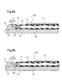
- Figs. 8A and 8B are schematic cross-sectional views showing a state where the bladder 10A is drawn out after the prepreg is cured.
- the hat stringer 20 has a rod shape or an elongated-plate shape extending in a particular direction.
- the hat stringer 20 includes a pair of flat band-shaped portions 20a which extend in parallel with each other in its lengthwise direction and a channel portion 20b which is located between the band-shaped portions 20a and is recessed from the surface of the flat portion.
- the upper surface of the channel portion 20b whose opening is directed downward as shown in Fig. 6A is referred to as an inner surface, while the upper surface of the channel portion 20b whose opening is directed upward is referred to as an outer surface.
- the bladder 10A is inserted into the channel portion 20b and used.
- the hat stringer 20 is assembled into a predetermined frame shape conforming to a shape of the structure (structural component). At this time, since the hat stringer 20 is assembled such that its outer surface is located at an outer side, the bladder 10A is inserted into the channel portion 20b. In this state, the prepreg 30 is bonded and attached to the outer surfaces of the band-shaped portions 20a of the hat stringer 20 and to the outer surface of the exposed wall portion 11b of the bladder 10A.
- a method of attaching the prepreg 30 to the outer surfaces is not particularly limited.
- the structure is a body of aircraft, its frame structure is assembled in a cylindrical shape.
- the prepreg 30 may be bonded and stacked while rotating the cylindrical frame structure.
- more layers are stacked together to increase the thickness of the skin in a portion which is required to have enhanced stiffness and strength.
- the skin is entirely thinned to achieve lightweight, while the skin is required to be thickened to enhance strength in a portion in the vicinity of a window, a door, or the like. Therefore, before curing, the thickness of the prepreg 30 is not constant.
- the mandrel 42 which is the jig for maintaining the cylindrical shape is attached to the interior of the cylindrical structure.
- the entire structure is covered with a bagging film 43 and is introduced into the autoclave. Inside the autoclave, this structure is heated under a predetermined temperature and pressurized under a predetermined pressure.
- a high-temperature and high-pressure atmosphere inside the autoclave is transmitted to the entire prepreg 30 via the bagging film 43, and to the interior of the bladder 10A through the pressurization hole 12a of the terminal metal member 12 of the bladder 10A (arrow HO in Fig. 7A ), so that the bladder 10A is inflated.
- the high-temperature and high-pressure atmosphere inside the autoclave is applied to the entire prepreg 30 (arrow H1 in Fig. 7A ).
- the plurality of (three in Fig. 7A ) adhesive layers 14 are formed between the outer peripheral surface of the insertion portion 12b and the inner surface of the body 11.
- the adhesive layers 14 are retained by the band-shaped groove portions 12d formed on the outer peripheral surface of the insertion portion 12b.
- a plurality of annular seal meterials formed by the adhesive layers 18 are provided on the outer peripheral surface of the insertion portion 12b. Because of this, the high-temperature and high-pressure atmosphere inside the bladder 10A does not leak through a clearance between the insertion portion 12b and the body 11, which enables the bladder 10A to be inflated sufficiently.
- the bladder 10A Since the bladder 10A is inflated, a state where the band-shaped portions 20a of the hat stringer 20 (not shown in Fig. 7A ) are pressed against the prepreg 30 by a strong external force is maintained, and curing of the prepreg 30 progresses. After the curing of the prepreg 30 is complete, a stiffened panel structure is attained, in which the frame constituted by the hat stringer 20 and the skin formed by curing the prepreg 30 are firmly adhesively attached to each other and integrated with each other.
- the bladder 10A is drawn out of the region between the cured skin 31 and the hat stringer 20.
- the bladder 10A is provided with the plurality of adhesive layers 14 between the outer peripheral surface of the insertion portion 12b of the terminal metal member 12 and the inner surface of the body 11, as surrounded by the dotted line in Fig. 8A . Since the adhesive layers 14 are formed at three locations which are the tip end side of the insertion portion 12b, the base end side of insertion portion 12b, and the portion between the tip end side and the base end side, the entire insertion portion 12b can be adhesively attached to the body 11.
- the skin 31 does not have a constant thickness, but has unevenness on its inner surface as indicated by a region D surrounded by the dotted line in Fig. 8A .
- the bladder 10A is inserted in between the hat stringer 20 and the skin 31 such that the upper portion of the bladder 10A is curved along the unevenness (region D).
- an external for pulling out the bladder 10A is applied to the head portion 12c of the terminal metal member 12, as indicated by an arrow P in Fig. 8A .
- the plurality of adhesive layers 14 surrounded by the dotted line in Fig. 8A allow the insertion portion 12b and the body 11 to be adhesively attached together stably. Therefore, even when the upper portion of the bladder 10A is curved along the unevenness of the inner surface of the skin 31, the bladder 10A can be drawn out by dragging the head portion 12c of the terminal metal member 12 to outside.
- the mandrel 42 is attached to the interior of the structure, and the entire structure is covered with the bagging film 43 and is introduced into the autoclave.
- the high-temperature and high-pressure atmosphere in the interior of the autoclave is applied to the entire prepreg 30 via the bagging film 43, and is transmitted to the interior of the bladder 10B through the pressurization hole 17a of the terminal metal member 17 of the bladder 10B (arrow HO in Fig. 7B ).
- the high-temperature and high-pressure atmosphere to be applied to the interior of the body 11 leaks from that portion where the body 11 is separated from the insertion portion 17b (arrow H2 in Fig. 7B ).
- the bladder 10B cannot be inflated sufficiently as described above, curing of the prepreg 30 might progress in a state where the band-shaped portions 20a of the hat stringer 20 which are not shown in Fig. 7B are not pressed against the prepreg 30 with a strong external force, and it becomes impossible to manufacture a structure having a proper shape. Therefore, if the adhesive state between the body 11 and the insertion portion 17b in the bladder 10B is insufficient, the bladder 10B cannot be used to manufacture a structure in a next occasion.
- the bladder 10A of the present invention is provided with the band-shaped groove portions 12d on the outer peripheral surface of the insertion portion 12b of the terminal metal member 12, the adhesive state between the terminal metal member 12 and the body 11 can be improved. Because of this, the bladder 10A is drawn out of the region between the cured skin 31 and the hat stringer 20 without lessening the adhesive state between the terminal metal member 12 and the body 11. As a result, the life of the bladder 10A can be extended.
- the adhesive layers 14 retained by the band-shaped groove portions 12d serve as the seal material on the outer peripheral surface of the insertion portion 12b, the air tightness in the interior of the body 11 can be improved more effectively, and the inflated state of the bladder 10A can be maintained stably.
- the present invention is suitably used in a field of manufacturing of composite material structures, in particular, in a field of manufacturing of a stiffened panel structure including a hat stringer.
Landscapes
- Engineering & Computer Science (AREA)
- Mechanical Engineering (AREA)
- Architecture (AREA)
- Civil Engineering (AREA)
- Structural Engineering (AREA)
- Chemical & Material Sciences (AREA)
- Composite Materials (AREA)
- Moulding By Coating Moulds (AREA)
Abstract
Description
- The present invention relates to a jig for use in manufacturing a composite material structure using a fiber-reinforced resin composite material. Particularly, the present invention relates to an inflatable bag-shaped jig (bladder) for use as a jig of a hat (hat-shaped) stringer in manufacturing a structure using the hat stringer as a frame member.
- In recent years, fiber-reinforced resin composite materials (hereinafter suitably referred to as "composite materials") have been widely used in fields in which metal materials have been used so far. Among the composite materials, carbon-fiber-reinforced materials which are formed such that carbon fibers used as reinforced fibers, are impregnated with matrix resin such as epoxy resin, have a smaller weight and a higher strength than metal materials. Because of this, the carbon-fiber-reinforced materials are widely used in fields of sport activity articles, industrial machines, and aerospace.
- Among these fields, in the field of aerospace, for example, in structures such as wings or bodies of aircraft, a stiffened panel in which a skin comprising a composite material is integrated with a stiffener which is a lightweight metal frame member, has been used. As a typical stiffener, there are a stringer and a frame. The stringer is a member having a relatively small thickness and is placed to extend in a lengthwise direction of the structure. The frame is a member having a relatively great thickness and is placed to cross the stringer in a direction (direction perpendicular to the lengthwise direction) of the transverse cross-section of the structure. The stringers are supported by jigs and arranged to conform to the shape of the structure. Plural sheets of prepreg are stacked together with the stringers, and the resulting stack is pressurized and heated in an autoclave. As a result, the prepreg is cured into skin, and the stringers are adhesively attached to and integrated with the skin. Further, the frame is attached to the stringers, thereby forming a stiffened panel.
- There are various kinds of stringers depending mainly on a difference in cross-sectional shape. To be specific, there are known a flat plate shape, a columnar shape, a C-shape, an I-shape, an L-shape, a Z-shape, and a hat shape. Among these, the hat stringer has recently attracted an attention, because it is suitable for weight saving of a structure, for the reason described below.
- The aircraft is required to minimize its weight, but is required to have a sufficient strength. Because of this, a thickness of the skin which is a body of the stiffened panel cannot be set constant, but is set greater in a region required to have a higher strength and smaller in a region which can provide a sufficient strength, thereby achieving a reduced weight. The jig supporting the stringer is an elongated member extending along the stringer, and defines a positional relationship between the prepreg and the stringer. The jig is drawn out along its lengthwise direction after the prepreg is cured. Because of this, if the skin has a uniform thickness, a surface of the skin which contacts the stringer is flat. Therefore, it is relatively easy to draw out the jig having supported the stringer after the prepreg is cured. However, if the skin has many non-uniform thickness regions, unevenness is generated in the surface of the skin which contacts the stringer. The jig is also curved to correspond to the unevenness. In this case, it is difficult to draw out the jig.
- The hat stringer has a pair of flat band-shaped portions extending in a lengthwise direction of the stringer, and a channel portion having a transverse cross-section recessed in a trapezoidal shape between the band-shaped portions. If the structure is a body of the aircraft formed of a one piece barrel (OPB), the band-shaped portions are surfaces (adhesion surfaces) adhesively attached to the inner surface of the skin. The hat stringers are placed along the lengthwise direction of the body with the adhesion surfaces being at an outer side, and the frame is placed in a circumferential direction of the body, thereby forming an assembly having a predetermined structure, for example, a cylindrical structure. The prepreg is wound around outside of the cylindrical structure and stacked thereon. Furthermore, a jig such as a mandrel is attached to the interior of the cylindrical structure. In a space formed between the skin and each of the hat stringers, i.e., inner side of the channel portion, an elongated jig called a bladder is inserted.
- The bladder is made of a material having flexibility and elasticity (stretchability). The bladder is inflatable (expandable) and contractible and has a structure of an elongated bag-shape. During a state where the bladder is inserted as the jig into the channel portion, an internal pressure is increased to allow the bladder to be inflated (expanded). Thus, the bladder maintains a state where the prepreg is stretched under tension to prevent the prepreg from being deformed between the band-shaped portions. At a time point when the prepreg has been cured into the skin, the internal pressure is lowered, and the bladder is contracted and drawn out of the channel portion. At this time, the band-shaped portions of the stringer are adhesively attached to and integrated with the inner surface of the skin. Therefore, it may be difficult to draw out a normal jig due to unevenness on the inner surface of the skin. However, at this time, the bladder has changed its state from the inflated state to the contacted state to have a smaller cross-section and has a flexibility, and therefore, the bladder can be easily drawn out of the channel portion without being affected by the unevenness.
- The bladder has a function similar to that of an inflatable mandrel. An exemplary inflatable mandrel has a configuration in which the mandrel is composed of plural layers and has a cylindrical bag shape inflatable and contractible, as disclosed in
Patent Literature 1. In this configuration, during molding, the mandrel is inflated and serves as an inner mold (core) with respect to an outer mold. In the contracted state, the mandrel is easily inserted into a cavity of the outer mold, and is easily drawn out of a molded drum-shaped object. As a specific manufacturing technique using the inflatable mandrel, for example,Patent Literature 2 discloses a manufacturing technique of a racket using the inflatable mandrel, andPatent Literature 3 discloses a technique for manufacturing a spar of a rotary wing aircraft using the inflatable mandrel. -
- Patent Literature 1:
U.S. Patent Publication No. 4632328 - Patent Literature 2: Japanese Laid-Open Patent Application Publication No.
Hei. 8-000770 - Patent Literature 3:
U.S. Patent Publication No. 5939007 - As described above, the general bladder has a configuration in which a terminal metal member which is a metal-made sealing member and has a pressurization hole for pressurizing the interior of a pipe-shaped body is attached to one end portion of the pipe-shaped body and a terminal plug which is a sealing member made of an elastic material is attached to the other end portion. In some cases, the bladder having the terminal metal member has a problem which is not assumed in the general inflatable mandrel.
- To be specific, the bladder serves as a "backing member" of the prepreg. Since the terminal metal member has the pressurization hole, the terminal metal member is not covered with the prepreg but is exposed in the channel portion in a state where the bladder is inserted into the channel portion of the hat stringer. This is because of the fact that when the hat stringer and the bladder are introduced into the autoclave and heated and pressurized therein, a pressurized atmosphere is transmitted to the interior of the body through the pressurization hole. Therefore, when the bladder is drawn out of the channel portion after treatment in the autoclave, the terminal metal member is dragged to outside.
- However, if the bladder is drawn out by dragging the terminal metal member to outside in repetition, a portion of the body and a portion of the terminal metal member which are adhesively attached together may be separated from each other, depending on the structure of the bladder. Even slight separation may lead to a phenomenon in which the pressurized atmosphere leaks from the interior of the body in the middle of the treatment in the autoclave, while significant separation may lead to a situation in which the bladder cannot be used. Such a problem will not exist in the techniques disclosed in
Patent Literature 1 toPatent Literature 3 in which the bladder is used only as the inner mold during the molding, but is unique to the bladder serving as the "backing member." - The present invention is directed to solving the above mentioned problem, and an object of the present invention is to provide a bladder-type jig which is suitably used to manufacture a stiffened panel structure using a hat stringer, among composite material structures, and can implement durability which enables repeated use.
- According to the present invention, there is provided a jig used for manufacturing a composite material structure, the jig being inserted into a channel portion of a hat stringer and used, when the composite material structure is manufactured by attaching prepreg to a frame structure including the hat stringer as a frame member, the channel portion extending in a lengthwise direction of the hat stringer; the jig comprising: a body having a pipe shape and made of an elastic material, the body having a transverse cross-section of a trapezoidal shape which is a cross-section perpendicular to a lengthwise direction of the body; and a terminal metal member attached to one end portion of the body and having a pressurization hole for pressurizing an interior of the body; wherein the terminal metal member has an insertion portion inserted into a hollow space of the body; the insertion portion has a columnar shape having a transverse cross-section conforming in shape to a contour shape of the hollow space of the body; the insertion portion is provided on an outer peripheral surface thereof with a band-shaped groove portion wound around the outer peripheral surface; and the insertion portion is inserted into the hollow space of the body in a state where an adhesive (adhesive agent) is filled in the band-shaped groove portion.
- In accordance with this configuration, the band-shaped groove portion provided on the insertion portion forms a space in which an adhesive is filled, and allows the filled adhesive to be retained in an annular shape like a seal material (sealing component) around the insertion portion, in a state where the insertion portion is inserted into the body. This makes it possible to improve an adhesive state between the terminal metal member and the body and improve air tightness in the interior of the body. Because of this, when the
jig used for manufacturing the composite material structure is drawn out of the region between the cured skin and the hat stringer, the adhesive state between the terminal metal member and the body is not reduced. As a result, a life of the jig used for manufacturing the composite material structure can be extended, and the inflated state of the jig used for manufacturing the composite material structure can be maintained stably. - In the jig used for manufacturing the composite material structure, preferably, the band-shaped groove portion includes a plurality of band-shaped groove portions provided on the insertion portion. The plurality of band-shaped groove portions can improve the adhesive state and the air tightness more effectively.
- In the jig used for manufacturing the composite material structure, the elastic material which is a material of the body is not particularly limited, but a heat resistant rubber composition material is preferably used. As the heat resistant rubber composition material, there are a silicone rubber composition material, a fluorine rubber composition material, etc..
- The above and further objects, features and advantages of the present invention will more fully be apparent from the following detailed description of preferred embodiments with accompanying drawings.
- As described above, in accordance with the present invention, the jig used for manufacturing the composite material structure is suitably used for manufacturing a stiffened panel structure using the hat stringer. The present invention has an advantage that durability of the jig for enabling repeated use of the jig is implemented.
-
- [
Fig. 1] Figs. 1A and 1B are schematic perspective views showing an exemplary external appearance configuration of a bladder as a jig used for manufacturing a composite material structure, according to an embodiment of the present invention. - [
Fig. 2] Fig. 2A is a sectional view of the bladder ofFig. 1 , in a lengthwise (longitudinal) direction, andFigs. 2B and 2C are perspective views showing exemplary structures of a body, and a terminal metal member constituting the bladder ofFig. 2A . - [
Fig. 3] Figs. 3A and 3B are schematic partial cross-sectional views showing steps for attaching the terminal metal member ofFig. 2C to the body. - [
Fig. 4] Figs. 4A and 4B are schematic partial cross-sectional views showing steps for attaching a standard terminal metal member to a body. - [
Fig. 5] Figs. 5A to 5F are schematic views showing specific shapes of band-shaped groove portions formed on an insertion portion. - [
Fig. 6] Figs. 6A and 6B are partial perspective views showing an exemplary configuration of the hat stringer. - [
Fig. 7] Figs. 7A and 7B are schematic cross-sectional views showing a positional relationship among the bladder, the prepreg, and a mandrel, in the step of curing the prepreg in an autoclave. - [
Fig. 8] Figs. 8A and 8B are schematic cross-sectional views showing a state where the bladder is drawn out after the prepreg is cured. -
- 10 bladder (jig used for manufacturing a composite material structure)
- 11 body
- 11a contact wall portion (wall portion corresponding to upper base of trapezoidal-shaped transverse cross-section)
- 11b exposed wall portion (wall portion corresponding to lower base of trapezoidal-shaped transverse cross-section)
- 12 terminal metal member (metal-made sealing member)
- 12a pressurization hole
- 12b insertion portion
- 13 terminal plug (sealing member made of elastic material)
- 17 terminal metal member (metal-made sealing member)
- 17a pressurization hole
- 17b insertion portion
- 20 hat stringer
- 20a band-shaped portion
- 20b channel portion
- 30 prepreg
- 31 skin
- Hereinafter, preferred embodiments of the present invention will be described with reference to the drawings. Throughout the drawings, the same or corresponding components are designated by the same reference numerals and repetitive description thereof will not be given.
-
Figs. 1A and 1B are schematic perspective views showing an exemplary external appearance configuration of a bladder as a jig used for manufacturing a composite material structure, according to the present embodiment.Fig. 2A is a sectional view of the bladder ofFig. 1 , in a lengthwise direction.Fig. 2B is a partial perspective view showing a shape of a body of the bladder ofFig. 1 .Fig. 2C is a perspective view showing a shape of aterminal metal member 12 attached to one end portion of the bladder ofFig. 1 . Hereinafter, the lengthwise direction of the bladder is referred to as "longitudinal direction," and a direction perpendicular to the longitudinal direction is referred to as "transverse direction." A cross-section of the bladder in the longitudinal direction is referred to as "longitudinal cross-section," and a cross-section of the bladder in the transverse direction is referred to as "transverse cross-section." - As shown in
Figs. 1A and 1B , abladder 10A according to the present embodiment has a columnar shape in its overall external appearance. Thebladder 10A includes at least abody 11, theterminal metal member 12, and aterminal plug 13. Thebody 11 is a member which becomes a main body of thebladder 10A, and has a hollow pipe shape as shown inFigs. 2A and 2B . - As shown in
Fig. 2B , thebody 11 has a transverse cross-section of a trapezoidal-shape. As described later, thebladder 10A is required to conform in shape to a channel portion formed on the hat stringer into which thebladder 10A is inserted. A wall portion of thebody 11 which corresponds to the upper base of the trapezoidal-shaped transverse cross-section is referred to as "contact wall portion 11a" in the present embodiment, as shown inFig. 1B and2B , because the outer surface of the wall portion contacts the channel portion of the hat stringer. A wall portion of thebody 11 which corresponds to the lower base of the trapezoidal-shaped transverse cross-section is referred to as "exposedwall portion 11b" in the present embodiment, as shown inFig. 1A and2B , because the outer surface of the wall portion is exposed in a state where thebladder 10A is inserted into the channel portion of the hat stringer. Therefore,Fig. 1A is a perspective view showing a state where the exposedwall portion 11b is the upper side, whileFig. 1B is a perspective view showing a state where thecontact wall portion 11a is the upper side. Of course, thecontact wall portion 11a (wall portion corresponding to the upper base) and the exposedwall portion 11b (wall portion corresponding to the lower base) which face each other are parallel to each other. - As shown in
Fig. 2B , in the present embodiment, the transverse cross-section of thebody 11 has a trapezoidal-shape, to be precise, an isosceles-trapezoidal shape, which is symmetric with respect to a line segment passing through a center point of the upper base and a center point of the lower base. When the wall portions of thebody 11, corresponding to oblique sides (lines) of the trapezoidal-shaped transverse cross-section, areinclined wall portions 11c, respectively, theinclined wall portions 11c are inclined in opposite directions with an equal inclination angle. The outer surfaces of theinclined wall portions 11c are surfaces contacting the channel portion of the hat stringer, like thecontact wall portion 11 a. - As shown in
Fig. 2A , thebody 11 is pipe-shaped and is sealed at both ends by theterminal metal member 12 and theterminal plug 13, respectively so that thebody 11 has a sealed inner space. Thebody 11 is made of an elastic material. As described later, thebody 11 is inflated by pressurization of the interior of thebody 11. The thicknesses of the wall portions of the body 11 (contact wall portion 11 a, exposedwall portion 11b andinclined wall portions 11c) of thebody 11, are required to provide flexibility which allows thebody 11 to be inflatable, although this depends on conditions such as a physical property of the elastic material and the degree to which thebody 11 is pressurized during use. In the present embodiment, as the elastic material constituting thebody 11, a known silicone rubber composition material is preferably used, as described later. Therefore, the thicknesses of the respective wall portions of thebody 11 are preferably within a range of 4.0 ~ 6.0mm, more preferably, a range of 4.5 ~ 5.5mm. If the thicknesses of the respective wall portions of thebody 11 are within this range, thebody 11 can be inflated sufficiently under pressurizing conditions described below, although it depends on a monomer structure or average molecular weight of silicone elastomer which is a major component of the silicone rubber composition material, or the kinds or composition of the components of the silicone rubber composition material. The thicknesses of the respective wall portions may be equal to or differed from each other. - As described above, the transverse-cross section of the
body 11 may be the trapezoidal shape conforming in shape to the channel portion of the hat stringer, and its specific dimension is not particularly limited. In the present embodiment, the length of the upper base of the transverse cross-section, i.e., the width of thecontact wall portion 11a is within a range of 20 ~ 25mm, the length of the lower base of the transverse cross-section, i.e., the width of the exposedwall portion 11b is within a range of 70 ~ 73mm, and the height H of the transverse cross-section, i.e., a distance between thecontact wall portion 11 a and the exposedwall portion 11b in thebody 11 is within a range of 34 ~ 37mm. However, the dimensions of the transverse cross-section of thebody 11 are not limited to these numeric value ranges, but are suitably set according to the shape of the channel portion of the hat stringer. - The overall length of the
body 11 is not particularly limited. As described later, thebladder 10A of the present embodiment is used as a jig used for manufacturing a composite material structure, and is inserted into each of channel portions of a plurality of hat stringers for use as a frame member of the composite material structure. Therefore, thebody 11 is designed to have various lengths. For example, when the composite material structure is a body of aircraft formed as a one piece barrel (OPB), the length of the hat stringer may be set to fall within a range of 1 ~ 10m. Therefore, the length of thebody 11 may be set to fall within a range of 1 ~ 10m, to conform to the length of the hat stringer. - The
terminal metal member 12 is a member for sealing one end portion of thebody 11. As shown inFig. 1A and2A , theterminal metal member 12 has apressurization hole 12a. In the present embodiment, as shown inFig. 2C , theterminal metal member 12 includes at least aninsertion portion 12b inserted into a hollow space of thebody 11 and ahead portion 12c connected to theinsertion portion 12b. Theinsertion portion 12b is adhesively attached to the inner surface of thebody 11 by an adhesive (agent) in a state where theterminal metal member 12 is inserted into thebody 11. Thehead portion 12c is exposed to outside in a state where theterminal metal member 12 is inserted into thebody 11. As shown inFig. 2C , a plurality of band-shapedgroove portions 12d are provided on the outer peripheral surface of theinsertion portion 12b to extend in a direction perpendicular to the longitudinal direction (extending direction of theinsertion portion 12b). - The
insertion portion 12b may conform in shape to the hollow space of thebody 11. In the present embodiment, as shown inFig. 2B , the wall portions of thebody 11 have an equal thickness, and therefore, the transverse cross-section of the hollow space has a trapezoidal shape. Therefore, theinsertion portion 12b has a short columnar shape in which its transverse cross-section has a trapezoidal shape. The length of theinsertion portion 12b is not particularly limited. The length of theinsertion portion 12b may ensure a sufficient contact area to maintain air tightness in the interior of thebody 11 in a state where theinsertion portion 12b is inserted into the hollow space of thebody 11 and adhesively attached to the inner surface of thebody 11 by the adhesive. In the present embodiment, the length of theinsertion portion 12b is within a range of, for example, 50 ~ 70mm. - As shown in
Fig. 2C , the band-shapedgroove portions 12d have a shape in which they are wound around the outer peripheral surface of theinsertion portion 12b in the lateral direction of theinsertion portion 12b, i.e., direction perpendicular to the direction (longitudinal direction, i.e., lengthwise direction of thebladder 10A) in which theinsertion portion 12b is inserted into the hollow space of thebody 11. Theterminal metal member 12 is fastened to thebody 11 in such a manner that an adhesive (adhesive agent) is applied to theinsertion portion 12b and theinsertion portion 12b is inserted into the hollow space of thebody 11. As described later, the band-shapedgroove portions 12d of theinsertion portion 12b allow theinsertion portion 12b and thebody 11 to be adhesively attached together in a state where the adhesive is filled in the band-shapedgroove portions 12d. This can improve an adhesive state between theterminal metal member 12 and thebody 11, and enhance air tightness in the interior of thebody 11. - The
head portion 12c may have a shape having a dimension sufficiently greater than a dimension of the hollow space of thebody 11 so that thehead portion 12c can be surely exposed to outside of thebody 11. As described later, the transverse cross-section of thehead portion 12c is preferably substantially equal to a dimension of the outer shape of thebody 11 so that thebladder 10A is easily inserted into the channel portion of the hat stringer. In this way, if the transverse cross-section of thehead portion 12c is substantially equal in size to the transverse cross-section of thebody 11, then the outer surfaces of the respective wall portions of thebladder 10A are substantially the same flat surfaces, to allow theentire bladder 10A to be inserted into and drawn out of the channel portion more easily. - In the present embodiment, the outer end of the
head portion 12c of theterminal metal member 12 is not flat but is an inclined surface protruding. To be specific, when the surface of theterminal metal member 12, corresponding to thecontact wall portion 11 a, is a contact surface, and the surface of theterminal metal member 12, corresponding to the exposedwall portion 11b, is an exposed surface, in a state where theterminal metal member 12 is attached to thebody 11, the contact surface of theterminal metal member 12 is flat and the exposed surface is inclined toward the contact surface as shown inFig. 2C . This allows the outer end surface of theterminal metal member 12 to be an inclined surface. Although not shown, the contact surface may have a width decreasing toward the outer end and its outer end may be pointed. If the outer end of thehead portion 12c is the inclined surface (or pointed surface), thebladder 10A is easily drawn out of the channel portion of the hat stringer into which thebody 11 is inserted. But, the shape of thehead portion 12c is not limited to this shape. The shape of theterminal metal member 12 is not limited to the above configuration in which it includes theinsertion portion 12b and thehead portion 12c, but may be configured to include another constituent. - As shown in
Figs. 1A and2A , theterminal metal member 12 has a structure in which one opening of thepressurization hole 12a is formed on the exposed surface of thehead portion 12c, and the other opening of thepressurization hole 12a is formed on the end surface of theinsertion portion 12b. InFig. 2C , the exposed surface of theterminal metal member 12 is at a lower side and therefore thepressurization hole 12a is not depicted. Thepressurization hole 12a is configured to extend substantially vertically from one opening formed on the exposed surface of thehead portion 12c toward an inside of thehead portion 12c, then is bent in a substantially center of thehead portion 12c toward theinsertion portion 12b, and further extends to the opening formed on the end surface of theinsertion portion 12b. Therefore, in a state where thebladder 10A is inserted into the channel portion of the hat stringer, one opening of thepressurization hole 12a is exposed in the exposed surface of thehead portion 12c of theterminal metal member 12, and the other opening of thepressurization hole 12a is connected to a hollow space of thebody 11. Therefore, thepressurization hole 12a is an air passage which provides communication between inside of thebody 11 and outside of thebody 11, and can pressurize the interior of thebody 11 sealed tightly. For example, in the interior of an autoclave in a high-pressure atmosphere, the interior of thebody 11 is placed in a high-pressure condition through thepressurization hole 12a, so that the interior of thebody 11 sealed tightly is pressurized and hence of thebody 11 is inflated. - In the present embodiment, as a material of the
terminal metal member 12, aluminum or alloy of aluminum is used. But, the material of theterminal metal member 12 is not limited this. Since thebladder 10A is used as the jig, theterminal metal member 12 is preferably made of a material having a smallest possible weight. In addition, theterminal metal member 12 is preferably made of a material which allows thepressurization hole 12a to be formed easily inside and its shape to be maintained easily. In view of this and to achieve cost saving, in the present embodiment, aluminum or alloy of aluminum is suitably used as the material of theterminal metal member 12. Depending on manufacturing conditions of a composite material structure, conditions other than "lightweight" may be sometimes considered as important. Therefore, for example, a known metal material other than aluminum, ceramic, or a heat-resistant resin composition material, may be selected, or a composite material of metals, ceramic, or heat-resistant resin composite materials may be used. - The
terminal plug 13 is a member for tightly sealing the other end portion (end portion on the opposite side of the end portion sealed by the terminal metal member 12) of thebody 11. In the present embodiment, as shown inFig. 2A , theterminal plug 13 includes aninsertion portion 13a inserted into the hollow space of thebody 11, and anouter lid portion 13b connected to theinsertion portion 13a. - Like the
insertion portion 12b of theterminal metal member 12, theinsertion portion 13a of theterminal plug 13 has a short-column shape with a transverse cross-section of a trapezoidal-shape to conform in shape to the transverse cross-section of the hollow space of thebody 11, while theouter lid portion 13b has a plate shape in which its outer diameter is substantially equal to the outer diameter of thebody 11. Like theinsertion portion 12b of theterminal metal member 12, the length of theinsertion portion 13a is not particularly limited, but may be a length for ensuring a sufficient contact area so that the interior of thebody 11 is maintained in a sealed condition in a state where theinsertion portion 13a is inserted into the hollow space of thebody 11 and is adhesively attached to the inner surface of thebody 11 by the adhesive. In the present embodiment, the length of theinsertion portion 13a is within a range of, for example, 20 ~ 30mm. - A specific shape of the
terminal plug 13 and specific dimensions of the constituents of theterminal plug 13 are not limited to the above configuration. For example, theterminal plug 13 may be configured to include constituents other than theinsertion portion 13a and theouter lid portion 13b as necessary. Or, theouter lid portion 13b may have a shape other than the plate shape so long as theterminal plug 13 can tightly seal the interior of thebody 11. - As described above, in the present embodiment, the
body 11 is sealed by two kinds of sealing members which are theterminal metal member 12 and theterminal plug 13. Of course, the present invention is not limited to this. Thebody 11 may be sealed by metal-made sealing members. Instead of using the separate member which is the sealing member, the pipe-shapedbody 11 may be secondarily molded to seal the opening at the other end portion of thebody 11. - In the
bladder 10A of the present embodiment, theterminal metal member 12 is adhesively attached to thebody 11 by the adhesive more firmly because of the band-shapedgroove portions 12d provided on the outer peripheral surface of theinsertion portion 12b. This will be described with reference toFigs. 3A and 3B andFigs. 4A and 4B , in conjunction with the manufacturing method of thebladder 10A. -
Figs. 3A and 3B are schematic partial cross-sectional views showing steps for attaching theterminal metal member 12 ofFig. 2C to thebody 11.Figs. 4A and 4B are schematic partial cross-sectional views showing the steps for attaching a standardterminal metal member 17 to thebody 11.Figs. 5A to 5F are schematic views showing specific shapes of the band-shapedgroove portions 12d formed on theinsertion portion 12b. - Firstly, the
body 11 is molded by a known molding method using a heat resistant rubber composition material, and theterminal metal member 12 and theterminal plug 13 are attached to the both ends of thebody 11 as the sealing members, respectively. At this time, as shown inFig. 3A , in a state where a known heatresistant adhesive 18 for use as a heat resistant rubber composition material is applied to theinsertion portion 12b of theterminal metal member 12 and theinsertion portion 13a of the terminal plug 13 (not shown), theinsertion portion 12b and theinsertion portion 13a are inserted into the end portions of thebody 11, respectively. - Typically, the size of the transverse cross-section of the
insertion portion 12b is set substantially equal to the size of the hollow space of the transverse cross-section of thebody 11, to improve air tightness in the interior of thebladder 10A. - If the size of the transverse cross-section of the
insertion portion 12b is smaller than the size of the hollow space of the transverse cross-section of thebody 11, there is a clearance between the outer peripheral surface of theinsertion portion 12b and the inner surface of thebody 11, in a state where theterminal metal member 12 is inserted into and fastened to thebody 11. This clearance is effective as the space for retaining the adhesive 18. Thebody 11 is inflated by pressurization of the interior of thebody 11. If the clearance is too great, the interior of thebody 11 cannot be maintained in an air-tight condition, although it depends on the degree of the adhesive state formed by the adhesive 18. In view of the degree to which thebody 11 is inflated, the size of the transverse cross-section of theinsertion portion 12b is preferably substantially equal to the size of the hollow space of the transverse cross-section of thebody 11. - As shown in
Fig. 3A , when theinsertion portion 12b of theterminal metal member 12 is inserted into the hollow space of thebody 11 in the state where the adhesive 18 is applied to the entire outer peripheral surface of theinsertion portion 12b of theterminal metal member 12, the adhesive 18 applied to the outer peripheral surface of theinsertion portion 12b is scraped by the opening edge of the end portion of thebody 11. Because of this, as shown inFig. 3B , when theinsertion portion 12b is inserted into the hollow space of thebody 11 substantially completely, a most part of the adhesive 18 is scraped from the outer peripheral surface of theinsertion portion 12b, and the scraped adhesive 18 gathers in a space between the opening of the end portion of thebody 11 and a stepped portion formed between thehead portion 12c and theinsertion portion 12b in theterminal metal member 12, and a part of it protrudes outward from the side surface of thebody 11 and the side surface of theterminal metal member 12. - The same applies to a case where the
standard terminal member 17 is attached to thebody 11 as shown inFig. 4A and 4B . As shown inFig. 4A , when the entire outer peripheral surface of aninsertion portion 17b of theterminal metal member 17 is applied with the adhesive 18 and theinsertion portion 17b is inserted into the hollow space of thebody 11, a most part of the adhesive 18 is scraped by the opening edge of the end portion of thebody 11, and the scraped adhesive 18 gathers in a space between the opening of the end portion of thebody 11 and a stepped portion formed between ahead portion 17c and theinsertion portion 17b in theterminal metal member 17 as shown inFig. 4B . - However, in the present embodiment, the plurality of (e.g., three) band-shaped
groove portions 12d are provided on the outer peripheral surface of theinsertion portion 12b to extend in the direction perpendicular to the longitudinal direction. In the case of the standardterminal metal member 17, as shown inFig. 4B , a most part of the adhesive 18 is removed from the outer peripheral surface of theinsertion portion 17b, when theinsertion portion 17b is inserted into the hollow space of thebody 11. However, in accordance with the configuration of the present embodiment, as shown inFig. 3B , the adhesive 18 is filled in the band-shapedgroove portions 12d and is left between theinsertion portion 12b and thebody 11. - As described above, the band-shaped
groove portions 12d are provided on the outer peripheral surface of theinsertion portion 12b to extend in the direction perpendicular to the longitudinal direction. Because of this, the adhesive 18 left between theinsertion portion 12b and thebody 11 is retained like an annular seal material between the outer peripheral surface of theinsertion portion 12b and the inner surface of thebody 11 and form a plurality of (e.g., three) adhesive layers 14. By curing the adhesive 18, theinsertion portion 12b and thebody 11 can be sufficiently adhesively attached together by the plurality ofadhesive layers 14, and can be joined together in a sealed state. This makes it possible to provide a more firmly adhesive state (secured state) between theterminal metal member 12 and thebody 11 and improve air tightness in the interior of thebody 11. - To particularly improve air tightness in the interior of the
body 11, the size of the transverse cross-section of theinsertion portion 12b may be set substantially equal to the size of the transverse cross-section of the hollow space of thebody 11. In accordance with this configuration, it is possible to prevent formation of a wasteful clearance between the outer peripheral surface of theinsertion portion 12b and the inner surface of thebody 11. However, in the case of the standardterminal metal member 17, the adhesive 18 cannot be retained between theinsertion portion 12b and thebody 11, if the size of the transverse cross-section of theinsertion portion 12b is set substantially equal to the size of the transverse cross-section of the hollow space of thebody 11. - By setting the clearance appropriately, the
body 11 can be kept in an air-tight condition, and the adhesive 18 can be retained appropriately. However, in the case of the standardterminal metal member 17, since the outer peripheral surface of theinsertion portion 12b is flat, it is difficult to retain the adhesive 18 stably. By comparison, in the present embodiment, since the plurality ofadhesive layers 14 can be formed by forming the plurality of band-shapedgroove portions 12d on the outer peripheral surface of theinsertion portion 12b, it is possible to adhesively attach theterminal metal member 12 to thebody 11 more surely. - The specific configuration of the band-shaped
groove portions 12d is not particularly limited. For example, as represented by oblique lines inFig.5A , band-shapedgroove portions 12d-1 may have a band shape in which they are wound around the outer peripheral surface of theinsertion portion 12b to extend along a direction (lateral direction) perpendicular to the longitudinal direction, but need not extend along the direction perpendicular to the longitudinal direction. For example, as represented by oblique lines inFig. 5B , a configuration in which band-shapedgroove portions 12d-2 are inclined with respect to the lateral direction, may be used. In a state where theinsertion portion 12b is inserted into thebody 11, the band-shapedgroove portions 12d not only serve as a space in which the adhesive 18 is filled (adhesive retaining function), but also serves to retain the filled adhesive 18 around theinsertion portion 12b in an annular shape, like a seal material (have a sealing function). The band-shapedgroove portions 12d may have any shape so long as they can implement such functions. - For example, as represented by oblique lines in
Fig. 5C , band-shapedgroove portions 12d-3 having a corrugated shape may be used. Or, as represented by oblique lines inFig. 5D , the band-shapedgroove portion 12d-1 having a greater width and a band-shapedgroove portion 12d-4 having a smaller width may coexist. Or, as represented by oblique lines inFig. 5E , a band-shapedgroove portion 12d-5 may be added to connect three band-shapedgroove portions 12d-1 in the longitudinal direction. Or, as represented by oblique lines inFig. 5F , standard band-shapedportions 12d-1 may be formed at a tip end side and a base end side of theinsertion portion 12b, and a broken-line-shapedrecess 12d-6 divided in a broken line shape may be formed between them. - By using a combination of the band-shaped
groove portion 12d-1 and the band-shapedgroove portion 12d-4 shown inFig. 5D , or a combination of the band-shapedgroove portion 12d-1 and the band-shapedgroove portion 12d-5 shown inFig. 5E , an area of theadhesive layers 14 can be advantageously increased. By using a combination of the band-shapedgroove portion 12d-1 and the broken-line-shapedrecess 12d-6 as shown inFig. 5F , the band-shapedgroove portions 12d-1 at the tip end side and at the base end side of theinsertion portion 12b provide the sealing function, and the broken-line-shapedrecess 12d-6 between them can form theadhesive layer 14 in the intermediate portion of theinsertion portion 12b. This can reduce the amount of the adhesive 18. - The dimension of the band-shaped
groove portion 12d is not particularly limited. For example, the width and depth of the band-shapedgroove portion 12d may be suitably set based on the specific dimension of theinsertion portion 12b and the specific dimension of thebody 11, provided that the adhesive retaining function and the sealing function can be implemented. In the present embodiment, the width of the band-shapedgroove portion 12d may be within a range of 2 ~ 5mm and the depth of the band-shapedgroove portion 12d may be within a range of 1 ~ 3mm, if the length of theinsertion portion 12b is 50mm. - The number of the band-shaped
groove portions 12d formed on theinsertion portion 12b is not particularly limited. To implement the adhesive retaining function and the sealing function, at least one band-shapedgroove portion 12d may be formed. To ensure a stably adhesive state over the entire outer peripheral surface of theinsertion portion 12b, the band-shapedgroove portions 12d are preferably formed at three locations which are the tip end side of theinsertion portion 12b, the base end side of thehead portion 12c, and a portion between them. That is, the band-shapedgroove portions 12d are preferably formed at three locations. Nonetheless, the band-shapedgroove portions 12d may be formed at two locations which are the tip end side and the base end side, or at two or more locations between the tip end side and the base end side, in view of conditions such as the length of theinsertion portion 12b, or a contact surface area of the band-shapedgroove portion 12d with the inner surface of thebody 11. - The
bladder 10A of the present embodiment is suitably used as a jig of a hat stringer included in a stiffener of a frame member, to manufacture various kinds of composite material structures using stiffened panels. This will be described with reference toFigs. 6A and 6B ,Figs. 7A and 7B , andFigs. 8A and 8B . -
Figs. 6A and 6B are partial perspective views showing an exemplary configuration of the hat stringer.Figs. 7A and 7B are schematic cross-sectional views showing a positional relationship among thebladder 10A, the prepreg, and a mandrel, in the step of curing the prepreg in the autoclave.Figs. 8A and 8B are schematic cross-sectional views showing a state where thebladder 10A is drawn out after the prepreg is cured. - As shown in
Figs. 6A and 6B , thehat stringer 20 has a rod shape or an elongated-plate shape extending in a particular direction. Thehat stringer 20 includes a pair of flat band-shapedportions 20a which extend in parallel with each other in its lengthwise direction and achannel portion 20b which is located between the band-shapedportions 20a and is recessed from the surface of the flat portion. The upper surface of thechannel portion 20b whose opening is directed downward as shown inFig. 6A is referred to as an inner surface, while the upper surface of thechannel portion 20b whose opening is directed upward is referred to as an outer surface. Thebladder 10A is inserted into thechannel portion 20b and used. - To be specific, the
hat stringer 20 is assembled into a predetermined frame shape conforming to a shape of the structure (structural component). At this time, since thehat stringer 20 is assembled such that its outer surface is located at an outer side, thebladder 10A is inserted into thechannel portion 20b. In this state, theprepreg 30 is bonded and attached to the outer surfaces of the band-shapedportions 20a of thehat stringer 20 and to the outer surface of the exposedwall portion 11b of thebladder 10A. - A method of attaching the
prepreg 30 to the outer surfaces is not particularly limited. For example, when the structure is a body of aircraft, its frame structure is assembled in a cylindrical shape. In this case, by using an automatic stacking machine including a stacking roller, theprepreg 30 may be bonded and stacked while rotating the cylindrical frame structure. Instead of bonding and attaching theprepreg 30 such that the thickness of the structure is uniform, more layers are stacked together to increase the thickness of the skin in a portion which is required to have enhanced stiffness and strength. For example, in the case of the body of the aircraft, the skin is entirely thinned to achieve lightweight, while the skin is required to be thickened to enhance strength in a portion in the vicinity of a window, a door, or the like. Therefore, before curing, the thickness of theprepreg 30 is not constant. - Then, as schematically shown in
Fig. 7A , in a state where stacking of theprepreg 30 is complete, themandrel 42 which is the jig for maintaining the cylindrical shape is attached to the interior of the cylindrical structure. In addition, the entire structure is covered with abagging film 43 and is introduced into the autoclave. Inside the autoclave, this structure is heated under a predetermined temperature and pressurized under a predetermined pressure. At this time, as shown inFig. 7A , a high-temperature and high-pressure atmosphere inside the autoclave is transmitted to theentire prepreg 30 via thebagging film 43, and to the interior of thebladder 10A through thepressurization hole 12a of theterminal metal member 12 of thebladder 10A (arrow HO inFig. 7A ), so that thebladder 10A is inflated. The high-temperature and high-pressure atmosphere inside the autoclave is applied to the entire prepreg 30 (arrow H1 inFig. 7A ). - As indicated by dotted-lines in
Fig. 7A , the plurality of (three inFig. 7A )adhesive layers 14 are formed between the outer peripheral surface of theinsertion portion 12b and the inner surface of thebody 11. The adhesive layers 14 are retained by the band-shapedgroove portions 12d formed on the outer peripheral surface of theinsertion portion 12b. This follows that a plurality of annular seal meterials formed by theadhesive layers 18 are provided on the outer peripheral surface of theinsertion portion 12b. Because of this, the high-temperature and high-pressure atmosphere inside thebladder 10A does not leak through a clearance between theinsertion portion 12b and thebody 11, which enables thebladder 10A to be inflated sufficiently. - Since the
bladder 10A is inflated, a state where the band-shapedportions 20a of the hat stringer 20 (not shown inFig. 7A ) are pressed against theprepreg 30 by a strong external force is maintained, and curing of theprepreg 30 progresses. After the curing of theprepreg 30 is complete, a stiffened panel structure is attained, in which the frame constituted by thehat stringer 20 and the skin formed by curing theprepreg 30 are firmly adhesively attached to each other and integrated with each other. - Thereafter, as shown in
Fig. 8A , thebladder 10A is drawn out of the region between the curedskin 31 and thehat stringer 20. In the present embodiment, as described above, thebladder 10A is provided with the plurality ofadhesive layers 14 between the outer peripheral surface of theinsertion portion 12b of theterminal metal member 12 and the inner surface of thebody 11, as surrounded by the dotted line inFig. 8A . Since theadhesive layers 14 are formed at three locations which are the tip end side of theinsertion portion 12b, the base end side ofinsertion portion 12b, and the portion between the tip end side and the base end side, theentire insertion portion 12b can be adhesively attached to thebody 11. - As described above, the
skin 31 does not have a constant thickness, but has unevenness on its inner surface as indicated by a region D surrounded by the dotted line inFig. 8A . As shown inFig. 8A , thebladder 10A is inserted in between thehat stringer 20 and theskin 31 such that the upper portion of thebladder 10A is curved along the unevenness (region D). When thebladder 10A is drawn out of the region between theskin 31 and thehat stringer 20, an external for pulling out thebladder 10A is applied to thehead portion 12c of theterminal metal member 12, as indicated by an arrow P inFig. 8A . - In accordance with the
bladder 10A of the present embodiment, the plurality ofadhesive layers 14 surrounded by the dotted line inFig. 8A allow theinsertion portion 12b and thebody 11 to be adhesively attached together stably. Therefore, even when the upper portion of thebladder 10A is curved along the unevenness of the inner surface of theskin 31, thebladder 10A can be drawn out by dragging thehead portion 12c of theterminal metal member 12 to outside. - By comparison, as shown in
Fig. 7B , in the case of abladder 10B including the standardterminal metal member 17, the adhesive is not sufficiently retained between theinsertion portion 17b and thebody 11, which frequently happens (seeFigs. 4A and 4B ). For this reason, if thebladder 10B is drawn out by pulling thehead portion 17c of theterminal metal member 17, as indicated by an arrow P inFig. 8B , the adhesive state between theterminal metal member 17 and thebody 11 is not retained sufficiently.
This may possibly cause theinsertion portion 17b to be disengaged away from thebody 11. In this case, thebladder 10B cannot be drawn out easily. In addition, depending on the state of the unevenness on the inner surface of theskin 31, thebladder 10B cannot be drawn out completely. - Even if the
insertion portion 17b is not disengaged away from thebody 11 completely but the inner surface of thebody 11 is separated from the outer peripheral surface of theinsertion portion 17b, the air tightness in the interior of thebody 11 which should be provided by theinsertion portion 17b cannot be maintained sufficiently. If the cylindrical structure is manufactured using thebladder 10B in such a state, as shown inFig. 7B , in a next occasion, the high-temperature and high-pressure atmosphere leaks from a portion where theinsertion portion 17b and thebody 11 are not adhesively attached together, which results in a situation where thebladder 10B cannot be inflated sufficiently. - To be specific, as described above, when the
prepreg 30 is cured, themandrel 42 is attached to the interior of the structure, and the entire structure is covered with the baggingfilm 43 and is introduced into the autoclave. As shown inFig. 7B , the high-temperature and high-pressure atmosphere in the interior of the autoclave is applied to theentire prepreg 30 via thebagging film 43, and is transmitted to the interior of thebladder 10B through thepressurization hole 17a of theterminal metal member 17 of thebladder 10B (arrow HO inFig. 7B ). If the inner surface of thebody 11 is separated from the outer peripheral surface of theinsertion portion 17b, the high-temperature and high-pressure atmosphere to be applied to the interior of thebody 11 leaks from that portion where thebody 11 is separated from theinsertion portion 17b (arrow H2 inFig. 7B ). - If the
bladder 10B cannot be inflated sufficiently as described above, curing of theprepreg 30 might progress in a state where the band-shapedportions 20a of thehat stringer 20 which are not shown inFig. 7B are not pressed against theprepreg 30 with a strong external force, and it becomes impossible to manufacture a structure having a proper shape. Therefore, if the adhesive state between thebody 11 and theinsertion portion 17b in thebladder 10B is insufficient, thebladder 10B cannot be used to manufacture a structure in a next occasion. - As described above, since the
bladder 10A of the present invention is provided with the band-shapedgroove portions 12d on the outer peripheral surface of theinsertion portion 12b of theterminal metal member 12, the adhesive state between theterminal metal member 12 and thebody 11 can be improved. Because of this, thebladder 10A is drawn out of the region between the curedskin 31 and thehat stringer 20 without lessening the adhesive state between theterminal metal member 12 and thebody 11.
As a result, the life of thebladder 10A can be extended. In addition, since theadhesive layers 14 retained by the band-shapedgroove portions 12d serve as the seal material on the outer peripheral surface of theinsertion portion 12b, the air tightness in the interior of thebody 11 can be improved more effectively, and the inflated state of thebladder 10A can be maintained stably. - Numerous modifications and alternative embodiments of the invention will be apparent to those skilled in the art in view of the foregoing description. Accordingly, the description is to be construed as illustrative only, and is provided for the purpose of teaching those skilled in the art the best mode of carrying out the invention. The details of the structure and/or function may be varied substantially without departing from the spirit of the invention and all modifications which come within the scope of the appended claims are reserved.
- The present invention is suitably used in a field of manufacturing of composite material structures, in particular, in a field of manufacturing of a stiffened panel structure including a hat stringer.
Claims (3)
- A jig used for manufacturing a composite material structure, the jig being inserted into a channel portion of a hat stringer and used, when the composite material structure is manufactured by attaching prepreg to a frame structure including the hat stringer as a frame member, the channel portion extending in a lengthwise direction of the hat stringer; the jig comprising:a body having a pipe shape and made of an elastic material, the body having a transverse cross-section of a trapezoidal shape which is a cross-section perpendicular to a lengthwise direction of the body; anda terminal metal member attached to one end portion of the body and having a pressurization hole for pressurizing an interior of the body;wherein the terminal metal member has an insertion portion inserted into a hollow space of the body;the insertion portion has a columnar shape having a transverse cross-section conforming in shape to a contour shape of the hollow space of the body;the insertion portion is provided on an outer peripheral surface thereof with a band-shaped groove portion wound around the outer peripheral surface; andthe insertion portion is inserted into the hollow space of the body in a state where an adhesive is filled in the band-shaped groove portion.
- The jig used for manufacturing the composite material structure according to Claim 1, wherein the band-shaped groove portion includes a plurality of band-shaped groove portions provided on the insertion portion.
- The jig used for manufacturing the composite material structure according to Claim 1 or 2, wherein the elastic material is a heat resistant rubber composition material.
Applications Claiming Priority (2)
| Application Number | Priority Date | Filing Date | Title |
|---|---|---|---|
| JP2009255520A JP5416554B2 (en) | 2009-11-06 | 2009-11-06 | Jig for manufacturing composite material structures |
| PCT/JP2010/006439 WO2011055524A1 (en) | 2009-11-06 | 2010-11-01 | Jig for manufacture of composite material structure |
Publications (3)
| Publication Number | Publication Date |
|---|---|
| EP2497623A1 true EP2497623A1 (en) | 2012-09-12 |
| EP2497623A4 EP2497623A4 (en) | 2017-11-29 |
| EP2497623B1 EP2497623B1 (en) | 2020-12-30 |
Family
ID=43969767
Family Applications (1)
| Application Number | Title | Priority Date | Filing Date |
|---|---|---|---|
| EP10828085.0A Active EP2497623B1 (en) | 2009-11-06 | 2010-11-01 | Jig used for manufacturing composite material structure |
Country Status (4)
| Country | Link |
|---|---|
| US (1) | US8602401B2 (en) |
| EP (1) | EP2497623B1 (en) |
| JP (1) | JP5416554B2 (en) |
| WO (1) | WO2011055524A1 (en) |
Cited By (2)
| Publication number | Priority date | Publication date | Assignee | Title |
|---|---|---|---|---|
| WO2016023736A1 (en) * | 2014-08-12 | 2016-02-18 | Bayerische Motoren Werke Aktiengesellschaft | Method for producing a fiber-reinforced plastic component |
| EP4029678A1 (en) * | 2021-01-04 | 2022-07-20 | The Boeing Company | Autoclave system, bladder assembly, and associated method for forming a part |
Families Citing this family (18)
| Publication number | Priority date | Publication date | Assignee | Title |
|---|---|---|---|---|
| DE102010024120B4 (en) * | 2010-06-17 | 2014-10-23 | Premium Aerotec Gmbh | support profile |
| US8684343B2 (en) * | 2012-01-06 | 2014-04-01 | Rubbercraft Corporation Of California Ltd | Composite fabrication vent assembly and method |
| US9352514B2 (en) * | 2013-06-19 | 2016-05-31 | The Boeing Company | Fuselage mandrel insert and method |
| JP6184808B2 (en) | 2013-09-05 | 2017-08-23 | 三菱重工業株式会社 | Manufacturing method of core type and hollow structure |
| US9623641B1 (en) * | 2013-09-24 | 2017-04-18 | The Boeing Company | Method and apparatus for reinforcing a bladder |
| US9914244B2 (en) * | 2014-08-04 | 2018-03-13 | The Boeing Company | Bladder system for curing composite parts |
| US9862122B2 (en) | 2014-08-14 | 2018-01-09 | The Boeing Company | Reinforced bladder |
| US10086534B2 (en) | 2014-10-17 | 2018-10-02 | The Boeing Company | Multifunctional mandrel end cap and method |
| US10507601B2 (en) | 2016-05-17 | 2019-12-17 | Rubbercraft Corporation Of California, Ltd. | Tri-layer bladder and related systems and methods for fabricating composite structures |
| CN109562578B (en) * | 2016-09-29 | 2020-12-08 | 株式会社斯巴鲁 | Composite structure and method of manufacturing composite structure |
| US20180194071A1 (en) * | 2017-01-06 | 2018-07-12 | Applied Composite Technology Aerospace, Inc. | Variable Volume Support Member for Cure of Composite Structure |
| CN110891752B (en) | 2017-07-25 | 2026-03-24 | 株式会社斯巴鲁 | Composite material forming fixtures and composite material forming methods |
| JP6971690B2 (en) * | 2017-08-03 | 2021-11-24 | 三菱重工業株式会社 | Manufacturing method for flexible mandrel and composite parts |
| BR112020006202B1 (en) | 2017-10-03 | 2023-12-26 | Rubbercraft Corporation Of California, Ltd | ELASTOMERIC TOOL FOR FORMING COMPOSITES |
| JP6715226B2 (en) | 2017-10-25 | 2020-07-01 | 株式会社Subaru | Composite material forming jig and composite material forming method |
| US11890823B2 (en) * | 2019-01-17 | 2024-02-06 | Kawasaki Jukogyo Kabushiki Kaisha | Composite material structure manufacturing jig, method of manufacturing the same, and method of manufacturing composite material structure |
| DE102019005910A1 (en) * | 2019-08-22 | 2021-02-25 | Siempelkamp Maschinen- Und Anlagenbau Gmbh | Method and device for producing a component |
| CN120840119A (en) * | 2024-11-14 | 2025-10-28 | 上海飞机制造有限公司 | Airbag assembly and mold assembly suitable for manufacturing hat-shaped long stringer reinforced wall panel components |
Family Cites Families (16)
| Publication number | Priority date | Publication date | Assignee | Title |
|---|---|---|---|---|
| US2139745A (en) * | 1937-04-07 | 1938-12-13 | Howard W Goodall | Hose coupling |
| CH459549A (en) * | 1966-07-15 | 1968-07-15 | Ciba Geigy | Process for the production of fiber-wound plastic pipe bends |
| US4632328A (en) | 1985-07-25 | 1986-12-30 | The B. F. Goodrich Company | Inflatable mandrel and method therefor |
| JP2935722B2 (en) * | 1990-02-28 | 1999-08-16 | 富士重工業株式会社 | Aircraft fuselage structure and molding method thereof |
| US5223067A (en) | 1990-02-28 | 1993-06-29 | Fuji Jukogyo Kabushiki Kaisha | Method of fabricating aircraft fuselage structure |
| JPH05116162A (en) * | 1991-04-30 | 1993-05-14 | Mitsubishi Heavy Ind Ltd | Composite material molding jig |
| US6143236A (en) * | 1994-02-09 | 2000-11-07 | Radius Engineering, Inc. | Method for manufacturing composite shafts with injection molded, rigidized bladder with varying wall thickness |
| JPH08770A (en) | 1994-06-17 | 1996-01-09 | Yonetsukusu Kk | Racket molding method |
| US5939007A (en) | 1994-08-31 | 1999-08-17 | Sikorsky Aircraft Corporation | Method for manufacture of a fiber reinforced composite spar for rotary wing aircraft |
| JPH08281833A (en) * | 1995-04-17 | 1996-10-29 | Nippon Oil Co Ltd | Fiber reinforced composite material roll |
| DE19932956B4 (en) * | 1998-07-15 | 2009-04-09 | Toyoda Gosei Co., Ltd. | hose connection |
| JP3938762B2 (en) * | 2003-05-30 | 2007-06-27 | 川崎重工業株式会社 | Plate-like structure, reinforcing material, and method for manufacturing plate-like structure |
| JP4928115B2 (en) * | 2005-11-08 | 2012-05-09 | 富士重工業株式会社 | Molding method and molding jig |
| FR2898539B1 (en) * | 2006-03-20 | 2008-05-23 | Eads Ccr Groupement D Interet | METHOD FOR PRODUCING RAIDIS PANELS IN COMPOSITE MATERIAL AND PANELS PRODUCED |
| DE102006035619B3 (en) * | 2006-07-31 | 2007-11-29 | Airbus Deutschland Gmbh | Connector for delivery of pressure medium to form core used in the manufacture of aerospace composite components |
| JP2009178988A (en) * | 2008-01-31 | 2009-08-13 | Kurashiki Kako Co Ltd | Hollow member for molding |
-
2009
- 2009-11-06 JP JP2009255520A patent/JP5416554B2/en active Active
-
2010
- 2010-11-01 EP EP10828085.0A patent/EP2497623B1/en active Active
- 2010-11-01 US US13/505,366 patent/US8602401B2/en active Active
- 2010-11-01 WO PCT/JP2010/006439 patent/WO2011055524A1/en not_active Ceased
Non-Patent Citations (1)
| Title |
|---|
| See references of WO2011055524A1 * |
Cited By (5)
| Publication number | Priority date | Publication date | Assignee | Title |
|---|---|---|---|---|
| WO2016023736A1 (en) * | 2014-08-12 | 2016-02-18 | Bayerische Motoren Werke Aktiengesellschaft | Method for producing a fiber-reinforced plastic component |
| CN106232334A (en) * | 2014-08-12 | 2016-12-14 | 宝马股份公司 | Method for producing fiber-reinforced plastic components |
| US10583587B2 (en) | 2014-08-12 | 2020-03-10 | Bayerische Motoren Werke Aktiengesellschaft | Method for producing a fiber-reinforced plastic component |
| EP4029678A1 (en) * | 2021-01-04 | 2022-07-20 | The Boeing Company | Autoclave system, bladder assembly, and associated method for forming a part |
| US12070915B2 (en) | 2021-01-04 | 2024-08-27 | The Boeing Company | Autoclave system, bladder assembly, and associated method for forming a part |
Also Published As
| Publication number | Publication date |
|---|---|
| JP5416554B2 (en) | 2014-02-12 |
| EP2497623A4 (en) | 2017-11-29 |
| JP2011098527A (en) | 2011-05-19 |
| WO2011055524A1 (en) | 2011-05-12 |
| EP2497623B1 (en) | 2020-12-30 |
| US8602401B2 (en) | 2013-12-10 |
| US20120235336A1 (en) | 2012-09-20 |
Similar Documents
| Publication | Publication Date | Title |
|---|---|---|
| EP2497623B1 (en) | Jig used for manufacturing composite material structure | |
| US7897004B2 (en) | Method for fabricating stringers | |
| KR101882535B1 (en) | Methods and systems for co-bonding or co-curing composite parts using a rigid/malleable smp apparatus | |
| US9278748B2 (en) | Processes to fabricate composite tubular-reinforced panels integrating skin and stringers and the panels thereby fabricated | |
| US11235494B2 (en) | Method of manufacturing composite material structure | |
| CN103180123B (en) | Method and system for forming one-piece composite parts with shape memory polymer devices | |
| EP2949458B1 (en) | Method for manufacturing carbon fiber panels stiffened with omega stringers | |
| US9120553B2 (en) | Process and a hollow body for producing a component having at least one hollow profile | |
| US9724848B2 (en) | Collapsible, coiled mandrel | |
| KR20090047445A (en) | Improved Composite Resin Window Frames for Aircraft | |
| KR20090128421A (en) | Method and apparatus for manufacturing parts from composite materials, especially aircraft body parts | |
| WO2022099707A1 (en) | Core mold for producing hat-shaped reinforcement member | |
| JP3938762B2 (en) | Plate-like structure, reinforcing material, and method for manufacturing plate-like structure | |
| US10052828B2 (en) | Supporting profiled element, method for producing a supporting profiled element, and use of said supporting profiled element in a method for producing a reinforced vehicle fuselage component | |
| CN109789650A (en) | Method of repairing composite stringers with composite repair caps | |
| CN114506095A (en) | Core mould for manufacturing cap-shaped reinforcing member | |
| CN111791517B (en) | Hollow saccular member repairing method | |
| US12485628B2 (en) | Composite material structure manufacturing jig, method of manufacturing the same, and method of manufacturing composite material structure | |
| CN120840119A (en) | Airbag assembly and mold assembly suitable for manufacturing hat-shaped long stringer reinforced wall panel components |
Legal Events
| Date | Code | Title | Description |
|---|---|---|---|
| PUAI | Public reference made under article 153(3) epc to a published international application that has entered the european phase |
Free format text: ORIGINAL CODE: 0009012 |
|
| 17P | Request for examination filed |
Effective date: 20120430 |
|
| AK | Designated contracting states |
Kind code of ref document: A1 Designated state(s): AL AT BE BG CH CY CZ DE DK EE ES FI FR GB GR HR HU IE IS IT LI LT LU LV MC MK MT NL NO PL PT RO RS SE SI SK SM TR |
|
| DAX | Request for extension of the european patent (deleted) | ||
| RA4 | Supplementary search report drawn up and despatched (corrected) |
Effective date: 20171030 |
|
| RIC1 | Information provided on ipc code assigned before grant |
Ipc: B29C 43/12 20060101ALI20171024BHEP Ipc: B29L 31/30 20060101ALI20171024BHEP Ipc: B64C 1/06 20060101ALI20171024BHEP Ipc: B29C 43/44 20060101ALI20171024BHEP Ipc: B29C 70/06 20060101AFI20171024BHEP |
|
| GRAP | Despatch of communication of intention to grant a patent |
Free format text: ORIGINAL CODE: EPIDOSNIGR1 |
|
| STAA | Information on the status of an ep patent application or granted ep patent |
Free format text: STATUS: GRANT OF PATENT IS INTENDED |
|
| INTG | Intention to grant announced |
Effective date: 20200730 |
|
| GRAS | Grant fee paid |
Free format text: ORIGINAL CODE: EPIDOSNIGR3 |
|
| RIN1 | Information on inventor provided before grant (corrected) |
Inventor name: TAKAHASHI, TOMOYA Inventor name: SANA, TOSHIKAZU Inventor name: HANAFUSA, YASUO |
|
| GRAA | (expected) grant |
Free format text: ORIGINAL CODE: 0009210 |
|
| STAA | Information on the status of an ep patent application or granted ep patent |
Free format text: STATUS: THE PATENT HAS BEEN GRANTED |
|
| AK | Designated contracting states |
Kind code of ref document: B1 Designated state(s): AL AT BE BG CH CY CZ DE DK EE ES FI FR GB GR HR HU IE IS IT LI LT LU LV MC MK MT NL NO PL PT RO RS SE SI SK SM TR |
|
| REG | Reference to a national code |
Ref country code: GB Ref legal event code: FG4D |
|
| REG | Reference to a national code |
Ref country code: DE Ref legal event code: R096 Ref document number: 602010066262 Country of ref document: DE |
|
| REG | Reference to a national code |
Ref country code: AT Ref legal event code: REF Ref document number: 1349503 Country of ref document: AT Kind code of ref document: T Effective date: 20210115 |
|
| REG | Reference to a national code |
Ref country code: IE Ref legal event code: FG4D |
|
| PG25 | Lapsed in a contracting state [announced via postgrant information from national office to epo] |
Ref country code: FI Free format text: LAPSE BECAUSE OF FAILURE TO SUBMIT A TRANSLATION OF THE DESCRIPTION OR TO PAY THE FEE WITHIN THE PRESCRIBED TIME-LIMIT Effective date: 20201230 Ref country code: RS Free format text: LAPSE BECAUSE OF FAILURE TO SUBMIT A TRANSLATION OF THE DESCRIPTION OR TO PAY THE FEE WITHIN THE PRESCRIBED TIME-LIMIT Effective date: 20201230 Ref country code: NO Free format text: LAPSE BECAUSE OF FAILURE TO SUBMIT A TRANSLATION OF THE DESCRIPTION OR TO PAY THE FEE WITHIN THE PRESCRIBED TIME-LIMIT Effective date: 20210330 Ref country code: GR Free format text: LAPSE BECAUSE OF FAILURE TO SUBMIT A TRANSLATION OF THE DESCRIPTION OR TO PAY THE FEE WITHIN THE PRESCRIBED TIME-LIMIT Effective date: 20210331 |
|
| REG | Reference to a national code |
Ref country code: AT Ref legal event code: MK05 Ref document number: 1349503 Country of ref document: AT Kind code of ref document: T Effective date: 20201230 |
|
| PG25 | Lapsed in a contracting state [announced via postgrant information from national office to epo] |
Ref country code: SE Free format text: LAPSE BECAUSE OF FAILURE TO SUBMIT A TRANSLATION OF THE DESCRIPTION OR TO PAY THE FEE WITHIN THE PRESCRIBED TIME-LIMIT Effective date: 20201230 Ref country code: LV Free format text: LAPSE BECAUSE OF FAILURE TO SUBMIT A TRANSLATION OF THE DESCRIPTION OR TO PAY THE FEE WITHIN THE PRESCRIBED TIME-LIMIT Effective date: 20201230 Ref country code: BG Free format text: LAPSE BECAUSE OF FAILURE TO SUBMIT A TRANSLATION OF THE DESCRIPTION OR TO PAY THE FEE WITHIN THE PRESCRIBED TIME-LIMIT Effective date: 20210330 |
|
| REG | Reference to a national code |
Ref country code: NL Ref legal event code: MP Effective date: 20201230 |
|
| PG25 | Lapsed in a contracting state [announced via postgrant information from national office to epo] |
Ref country code: HR Free format text: LAPSE BECAUSE OF FAILURE TO SUBMIT A TRANSLATION OF THE DESCRIPTION OR TO PAY THE FEE WITHIN THE PRESCRIBED TIME-LIMIT Effective date: 20201230 |
|
| REG | Reference to a national code |
Ref country code: LT Ref legal event code: MG9D |
|
| PG25 | Lapsed in a contracting state [announced via postgrant information from national office to epo] |
Ref country code: SK Free format text: LAPSE BECAUSE OF FAILURE TO SUBMIT A TRANSLATION OF THE DESCRIPTION OR TO PAY THE FEE WITHIN THE PRESCRIBED TIME-LIMIT Effective date: 20201230 Ref country code: PT Free format text: LAPSE BECAUSE OF FAILURE TO SUBMIT A TRANSLATION OF THE DESCRIPTION OR TO PAY THE FEE WITHIN THE PRESCRIBED TIME-LIMIT Effective date: 20210430 Ref country code: RO Free format text: LAPSE BECAUSE OF FAILURE TO SUBMIT A TRANSLATION OF THE DESCRIPTION OR TO PAY THE FEE WITHIN THE PRESCRIBED TIME-LIMIT Effective date: 20201230 Ref country code: CZ Free format text: LAPSE BECAUSE OF FAILURE TO SUBMIT A TRANSLATION OF THE DESCRIPTION OR TO PAY THE FEE WITHIN THE PRESCRIBED TIME-LIMIT Effective date: 20201230 Ref country code: EE Free format text: LAPSE BECAUSE OF FAILURE TO SUBMIT A TRANSLATION OF THE DESCRIPTION OR TO PAY THE FEE WITHIN THE PRESCRIBED TIME-LIMIT Effective date: 20201230 Ref country code: NL Free format text: LAPSE BECAUSE OF FAILURE TO SUBMIT A TRANSLATION OF THE DESCRIPTION OR TO PAY THE FEE WITHIN THE PRESCRIBED TIME-LIMIT Effective date: 20201230 Ref country code: LT Free format text: LAPSE BECAUSE OF FAILURE TO SUBMIT A TRANSLATION OF THE DESCRIPTION OR TO PAY THE FEE WITHIN THE PRESCRIBED TIME-LIMIT Effective date: 20201230 |
|
| PG25 | Lapsed in a contracting state [announced via postgrant information from national office to epo] |
Ref country code: PL Free format text: LAPSE BECAUSE OF FAILURE TO SUBMIT A TRANSLATION OF THE DESCRIPTION OR TO PAY THE FEE WITHIN THE PRESCRIBED TIME-LIMIT Effective date: 20201230 Ref country code: AT Free format text: LAPSE BECAUSE OF FAILURE TO SUBMIT A TRANSLATION OF THE DESCRIPTION OR TO PAY THE FEE WITHIN THE PRESCRIBED TIME-LIMIT Effective date: 20201230 |
|
| PG25 | Lapsed in a contracting state [announced via postgrant information from national office to epo] |
Ref country code: IS Free format text: LAPSE BECAUSE OF FAILURE TO SUBMIT A TRANSLATION OF THE DESCRIPTION OR TO PAY THE FEE WITHIN THE PRESCRIBED TIME-LIMIT Effective date: 20210430 |
|
| REG | Reference to a national code |
Ref country code: DE Ref legal event code: R097 Ref document number: 602010066262 Country of ref document: DE |
|
| PG25 | Lapsed in a contracting state [announced via postgrant information from national office to epo] |
Ref country code: AL Free format text: LAPSE BECAUSE OF FAILURE TO SUBMIT A TRANSLATION OF THE DESCRIPTION OR TO PAY THE FEE WITHIN THE PRESCRIBED TIME-LIMIT Effective date: 20201230 |
|
| PLBE | No opposition filed within time limit |
Free format text: ORIGINAL CODE: 0009261 |
|
| STAA | Information on the status of an ep patent application or granted ep patent |
Free format text: STATUS: NO OPPOSITION FILED WITHIN TIME LIMIT |
|
| PG25 | Lapsed in a contracting state [announced via postgrant information from national office to epo] |
Ref country code: DK Free format text: LAPSE BECAUSE OF FAILURE TO SUBMIT A TRANSLATION OF THE DESCRIPTION OR TO PAY THE FEE WITHIN THE PRESCRIBED TIME-LIMIT Effective date: 20201230 Ref country code: ES Free format text: LAPSE BECAUSE OF FAILURE TO SUBMIT A TRANSLATION OF THE DESCRIPTION OR TO PAY THE FEE WITHIN THE PRESCRIBED TIME-LIMIT Effective date: 20201230 |
|
| 26N | No opposition filed |
Effective date: 20211001 |
|
| PG25 | Lapsed in a contracting state [announced via postgrant information from national office to epo] |
Ref country code: SI Free format text: LAPSE BECAUSE OF FAILURE TO SUBMIT A TRANSLATION OF THE DESCRIPTION OR TO PAY THE FEE WITHIN THE PRESCRIBED TIME-LIMIT Effective date: 20201230 |
|
| PG25 | Lapsed in a contracting state [announced via postgrant information from national office to epo] |
Ref country code: IS Free format text: LAPSE BECAUSE OF FAILURE TO SUBMIT A TRANSLATION OF THE DESCRIPTION OR TO PAY THE FEE WITHIN THE PRESCRIBED TIME-LIMIT Effective date: 20210430 |
|
| PG25 | Lapsed in a contracting state [announced via postgrant information from national office to epo] |
Ref country code: MC Free format text: LAPSE BECAUSE OF FAILURE TO SUBMIT A TRANSLATION OF THE DESCRIPTION OR TO PAY THE FEE WITHIN THE PRESCRIBED TIME-LIMIT Effective date: 20201230 |
|
| REG | Reference to a national code |
Ref country code: CH Ref legal event code: PL |
|
| GBPC | Gb: european patent ceased through non-payment of renewal fee |
Effective date: 20211101 |
|
| PG25 | Lapsed in a contracting state [announced via postgrant information from national office to epo] |
Ref country code: LU Free format text: LAPSE BECAUSE OF NON-PAYMENT OF DUE FEES Effective date: 20211101 Ref country code: BE Free format text: LAPSE BECAUSE OF NON-PAYMENT OF DUE FEES Effective date: 20211130 |
|
| REG | Reference to a national code |
Ref country code: BE Ref legal event code: MM Effective date: 20211130 |
|
| PG25 | Lapsed in a contracting state [announced via postgrant information from national office to epo] |
Ref country code: IE Free format text: LAPSE BECAUSE OF NON-PAYMENT OF DUE FEES Effective date: 20211101 Ref country code: GB Free format text: LAPSE BECAUSE OF NON-PAYMENT OF DUE FEES Effective date: 20211101 |
|
| PG25 | Lapsed in a contracting state [announced via postgrant information from national office to epo] |
Ref country code: HU Free format text: LAPSE BECAUSE OF FAILURE TO SUBMIT A TRANSLATION OF THE DESCRIPTION OR TO PAY THE FEE WITHIN THE PRESCRIBED TIME-LIMIT; INVALID AB INITIO Effective date: 20101101 Ref country code: CY Free format text: LAPSE BECAUSE OF FAILURE TO SUBMIT A TRANSLATION OF THE DESCRIPTION OR TO PAY THE FEE WITHIN THE PRESCRIBED TIME-LIMIT Effective date: 20201230 |
|
| PG25 | Lapsed in a contracting state [announced via postgrant information from national office to epo] |
Ref country code: SM Free format text: LAPSE BECAUSE OF FAILURE TO SUBMIT A TRANSLATION OF THE DESCRIPTION OR TO PAY THE FEE WITHIN THE PRESCRIBED TIME-LIMIT Effective date: 20201230 Ref country code: LI Free format text: LAPSE BECAUSE OF NON-PAYMENT OF DUE FEES Effective date: 20220630 Ref country code: CH Free format text: LAPSE BECAUSE OF NON-PAYMENT OF DUE FEES Effective date: 20220630 |
|
| PG25 | Lapsed in a contracting state [announced via postgrant information from national office to epo] |
Ref country code: MK Free format text: LAPSE BECAUSE OF FAILURE TO SUBMIT A TRANSLATION OF THE DESCRIPTION OR TO PAY THE FEE WITHIN THE PRESCRIBED TIME-LIMIT Effective date: 20201230 |
|
| PG25 | Lapsed in a contracting state [announced via postgrant information from national office to epo] |
Ref country code: TR Free format text: LAPSE BECAUSE OF FAILURE TO SUBMIT A TRANSLATION OF THE DESCRIPTION OR TO PAY THE FEE WITHIN THE PRESCRIBED TIME-LIMIT Effective date: 20201230 |
|
| PG25 | Lapsed in a contracting state [announced via postgrant information from national office to epo] |
Ref country code: MT Free format text: LAPSE BECAUSE OF FAILURE TO SUBMIT A TRANSLATION OF THE DESCRIPTION OR TO PAY THE FEE WITHIN THE PRESCRIBED TIME-LIMIT Effective date: 20201230 |
|
| PGFP | Annual fee paid to national office [announced via postgrant information from national office to epo] |
Ref country code: FR Payment date: 20250930 Year of fee payment: 16 |
|
| PGFP | Annual fee paid to national office [announced via postgrant information from national office to epo] |
Ref country code: DE Payment date: 20250930 Year of fee payment: 16 |
|
| PGFP | Annual fee paid to national office [announced via postgrant information from national office to epo] |
Ref country code: IT Payment date: 20251022 Year of fee payment: 16 |