EP2497581A1 - Method for manufacturing beam, and beam - Google Patents
Method for manufacturing beam, and beam Download PDFInfo
- Publication number
- EP2497581A1 EP2497581A1 EP11157809A EP11157809A EP2497581A1 EP 2497581 A1 EP2497581 A1 EP 2497581A1 EP 11157809 A EP11157809 A EP 11157809A EP 11157809 A EP11157809 A EP 11157809A EP 2497581 A1 EP2497581 A1 EP 2497581A1
- Authority
- EP
- European Patent Office
- Prior art keywords
- web plate
- jig
- welding
- flange
- parts
- Prior art date
- Legal status (The legal status is an assumption and is not a legal conclusion. Google has not performed a legal analysis and makes no representation as to the accuracy of the status listed.)
- Granted
Links
Images


Classifications
-
- E—FIXED CONSTRUCTIONS
- E04—BUILDING
- E04C—STRUCTURAL ELEMENTS; BUILDING MATERIALS
- E04C3/00—Structural elongated elements designed for load-supporting
- E04C3/02—Joists; Girders, trusses, or trusslike structures, e.g. prefabricated; Lintels; Transoms; Braces
- E04C3/04—Joists; Girders, trusses, or trusslike structures, e.g. prefabricated; Lintels; Transoms; Braces of metal
- E04C3/08—Joists; Girders, trusses, or trusslike structures, e.g. prefabricated; Lintels; Transoms; Braces of metal with apertured web, e.g. with a web consisting of bar-like components; Honeycomb girders
-
- E—FIXED CONSTRUCTIONS
- E01—CONSTRUCTION OF ROADS, RAILWAYS, OR BRIDGES
- E01B—PERMANENT WAY; PERMANENT-WAY TOOLS; MACHINES FOR MAKING RAILWAYS OF ALL KINDS
- E01B25/00—Tracks for special kinds of railways
- E01B25/30—Tracks for magnetic suspension or levitation vehicles
- E01B25/305—Rails or supporting constructions
-
- B—PERFORMING OPERATIONS; TRANSPORTING
- B21—MECHANICAL METAL-WORKING WITHOUT ESSENTIALLY REMOVING MATERIAL; PUNCHING METAL
- B21D—WORKING OR PROCESSING OF SHEET METAL OR METAL TUBES, RODS OR PROFILES WITHOUT ESSENTIALLY REMOVING MATERIAL; PUNCHING METAL
- B21D47/00—Making rigid structural elements or units, e.g. honeycomb structures
- B21D47/04—Making rigid structural elements or units, e.g. honeycomb structures composite sheet metal profiles
-
- B—PERFORMING OPERATIONS; TRANSPORTING
- B23—MACHINE TOOLS; METAL-WORKING NOT OTHERWISE PROVIDED FOR
- B23K—SOLDERING OR UNSOLDERING; WELDING; CLADDING OR PLATING BY SOLDERING OR WELDING; CUTTING BY APPLYING HEAT LOCALLY, e.g. FLAME CUTTING; WORKING BY LASER BEAM
- B23K31/00—Processes relevant to this subclass, specially adapted for particular articles or purposes, but not covered by any single one of main groups B23K1/00 - B23K28/00
- B23K31/02—Processes relevant to this subclass, specially adapted for particular articles or purposes, but not covered by any single one of main groups B23K1/00 - B23K28/00 relating to soldering or welding
- B23K31/022—Making profiled bars with soldered or welded seams
-
- E—FIXED CONSTRUCTIONS
- E04—BUILDING
- E04B—GENERAL BUILDING CONSTRUCTIONS; WALLS, e.g. PARTITIONS; ROOFS; FLOORS; CEILINGS; INSULATION OR OTHER PROTECTION OF BUILDINGS
- E04B5/00—Floors; Floor construction with regard to insulation; Connections specially adapted therefor
- E04B5/16—Load-carrying floor structures wholly or partly cast or similarly formed in situ
- E04B5/17—Floor structures partly formed in situ
- E04B5/23—Floor structures partly formed in situ with stiffening ribs or other beam-like formations wholly or partly prefabricated
- E04B5/29—Floor structures partly formed in situ with stiffening ribs or other beam-like formations wholly or partly prefabricated the prefabricated parts of the beams consisting wholly of metal
-
- E—FIXED CONSTRUCTIONS
- E04—BUILDING
- E04C—STRUCTURAL ELEMENTS; BUILDING MATERIALS
- E04C3/00—Structural elongated elements designed for load-supporting
- E04C3/02—Joists; Girders, trusses, or trusslike structures, e.g. prefabricated; Lintels; Transoms; Braces
- E04C3/04—Joists; Girders, trusses, or trusslike structures, e.g. prefabricated; Lintels; Transoms; Braces of metal
- E04C3/06—Joists; Girders, trusses, or trusslike structures, e.g. prefabricated; Lintels; Transoms; Braces of metal with substantially solid, i.e. unapertured, web
-
- E—FIXED CONSTRUCTIONS
- E04—BUILDING
- E04C—STRUCTURAL ELEMENTS; BUILDING MATERIALS
- E04C3/00—Structural elongated elements designed for load-supporting
- E04C3/02—Joists; Girders, trusses, or trusslike structures, e.g. prefabricated; Lintels; Transoms; Braces
- E04C3/12—Joists; Girders, trusses, or trusslike structures, e.g. prefabricated; Lintels; Transoms; Braces of wood, e.g. with reinforcements, with tensioning members
- E04C3/16—Joists; Girders, trusses, or trusslike structures, e.g. prefabricated; Lintels; Transoms; Braces of wood, e.g. with reinforcements, with tensioning members with apertured web, e.g. trusses
-
- B—PERFORMING OPERATIONS; TRANSPORTING
- B23—MACHINE TOOLS; METAL-WORKING NOT OTHERWISE PROVIDED FOR
- B23K—SOLDERING OR UNSOLDERING; WELDING; CLADDING OR PLATING BY SOLDERING OR WELDING; CUTTING BY APPLYING HEAT LOCALLY, e.g. FLAME CUTTING; WORKING BY LASER BEAM
- B23K2101/00—Articles made by soldering, welding or cutting
- B23K2101/28—Beams
-
- B—PERFORMING OPERATIONS; TRANSPORTING
- B23—MACHINE TOOLS; METAL-WORKING NOT OTHERWISE PROVIDED FOR
- B23K—SOLDERING OR UNSOLDERING; WELDING; CLADDING OR PLATING BY SOLDERING OR WELDING; CUTTING BY APPLYING HEAT LOCALLY, e.g. FLAME CUTTING; WORKING BY LASER BEAM
- B23K31/00—Processes relevant to this subclass, specially adapted for particular articles or purposes, but not covered by any single one of main groups B23K1/00 - B23K28/00
- B23K31/02—Processes relevant to this subclass, specially adapted for particular articles or purposes, but not covered by any single one of main groups B23K1/00 - B23K28/00 relating to soldering or welding
-
- E—FIXED CONSTRUCTIONS
- E01—CONSTRUCTION OF ROADS, RAILWAYS, OR BRIDGES
- E01B—PERMANENT WAY; PERMANENT-WAY TOOLS; MACHINES FOR MAKING RAILWAYS OF ALL KINDS
- E01B25/00—Tracks for special kinds of railways
- E01B25/08—Tracks for mono-rails with centre of gravity of vehicle above the load-bearing rail
-
- E—FIXED CONSTRUCTIONS
- E04—BUILDING
- E04C—STRUCTURAL ELEMENTS; BUILDING MATERIALS
- E04C3/00—Structural elongated elements designed for load-supporting
- E04C3/02—Joists; Girders, trusses, or trusslike structures, e.g. prefabricated; Lintels; Transoms; Braces
- E04C3/04—Joists; Girders, trusses, or trusslike structures, e.g. prefabricated; Lintels; Transoms; Braces of metal
- E04C2003/0404—Joists; Girders, trusses, or trusslike structures, e.g. prefabricated; Lintels; Transoms; Braces of metal beams, girders, or joists characterised by cross-sectional aspects
- E04C2003/0408—Joists; Girders, trusses, or trusslike structures, e.g. prefabricated; Lintels; Transoms; Braces of metal beams, girders, or joists characterised by cross-sectional aspects characterised by assembly or the cross-section
- E04C2003/0413—Joists; Girders, trusses, or trusslike structures, e.g. prefabricated; Lintels; Transoms; Braces of metal beams, girders, or joists characterised by cross-sectional aspects characterised by assembly or the cross-section being built up from several parts
-
- E—FIXED CONSTRUCTIONS
- E04—BUILDING
- E04C—STRUCTURAL ELEMENTS; BUILDING MATERIALS
- E04C3/00—Structural elongated elements designed for load-supporting
- E04C3/02—Joists; Girders, trusses, or trusslike structures, e.g. prefabricated; Lintels; Transoms; Braces
- E04C3/04—Joists; Girders, trusses, or trusslike structures, e.g. prefabricated; Lintels; Transoms; Braces of metal
- E04C2003/0404—Joists; Girders, trusses, or trusslike structures, e.g. prefabricated; Lintels; Transoms; Braces of metal beams, girders, or joists characterised by cross-sectional aspects
- E04C2003/0426—Joists; Girders, trusses, or trusslike structures, e.g. prefabricated; Lintels; Transoms; Braces of metal beams, girders, or joists characterised by cross-sectional aspects characterised by material distribution in cross section
- E04C2003/043—Joists; Girders, trusses, or trusslike structures, e.g. prefabricated; Lintels; Transoms; Braces of metal beams, girders, or joists characterised by cross-sectional aspects characterised by material distribution in cross section the hollow cross-section comprising at least one enclosed cavity
-
- E—FIXED CONSTRUCTIONS
- E04—BUILDING
- E04C—STRUCTURAL ELEMENTS; BUILDING MATERIALS
- E04C3/00—Structural elongated elements designed for load-supporting
- E04C3/02—Joists; Girders, trusses, or trusslike structures, e.g. prefabricated; Lintels; Transoms; Braces
- E04C3/04—Joists; Girders, trusses, or trusslike structures, e.g. prefabricated; Lintels; Transoms; Braces of metal
- E04C2003/0404—Joists; Girders, trusses, or trusslike structures, e.g. prefabricated; Lintels; Transoms; Braces of metal beams, girders, or joists characterised by cross-sectional aspects
- E04C2003/0443—Joists; Girders, trusses, or trusslike structures, e.g. prefabricated; Lintels; Transoms; Braces of metal beams, girders, or joists characterised by cross-sectional aspects characterised by substantial shape of the cross-section
- E04C2003/0465—Joists; Girders, trusses, or trusslike structures, e.g. prefabricated; Lintels; Transoms; Braces of metal beams, girders, or joists characterised by cross-sectional aspects characterised by substantial shape of the cross-section square- or rectangular-shaped
Definitions
- the invention relates to a beam, and especially to a rail beam, and to a method for its manufacture.
- a beam is a horizontal or inclined support used in construction engineering.
- the task of a beam in a structure is to support upper structures, such as floor slabs, roof, ceiling, bulkhead, bridge, road, or rails, for instance.
- the beam has a precise specification, definition, and instructions according to which the beam is to be manufactured during the manufacturing phase.
- the manufacture of a steel rail beam of a train has to be done manually.
- a positioning mould or fasteners or jig is/are made for the rail beam.
- a problem with the prior art is that the rail beam does not keep to the tolerances in the jig after manufacturing due to deformations caused by heat input directed to the seams of the beam during manufacturing.
- the beam does not meet the vertical tolerance, up/down tolerance and/or horizontal tolerance, left/right tolerance.
- a finished beam that is not according to the tolerances also cannot be straightened or made to comply with the specification afterward.
- the invention is based on the fact that the heat input used in manufacturing the beam is controlled and monitored centrally and, thus, the manufacturing tolerances are achieved by the method and apparatus of the invention and its preferred embodiments.
- the method and system of the invention provides the advantage that it is possible to manufacture during the manufacturing process automatically a dimensionally accurate beam according to the specification, that is, a final product complying with the manufacturing tolerances.
- a jig refers to the central web of the rail beam of the magnetic train, that is, the mould, positioning mould, or fasteners according to which or supported by which the beam or a part thereof can be made.
- a jig can also refer to the shape or mould of a three-web beam, to which the beam is set in a first step so as to make the rest of the beam in a second step. In the case of a three-web beam, for instance, the jig is formed in the first step and then used as support or mould in the second step of manufacturing the beam.
- the jig may be an H beam, H portion, or H jig that serves as a mould as the side plates are added.
- the central web may also be perforated.
- a jig may also refer to a jig built inside the beam. The central web may serve as the jig, and the jig may accompany the finished beam until its installation.
- the internal jig may be symmetric or asymmetric
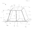
- Figures 1 and 2 show the first and second beams according to the invention and its preferred embodiments.
- the beams have two horizontal plate-like parts or flanges and three vertical plate-like parts or webs: edge webs 1-2, 1-4 ( Figure 1 ) and 2-2, 2-4 ( Figure 2 ) and a third web or central web 1-6 ( Figure 1 ) and 2-6 ( Figure 2 ) between the edge webs.
- the webs can be joined at their first ends fixedly or detachably to a first horizontal plate-like part or flange, for instance bottom flange 1-10, 2-20 ( Figures 1 and 2 ).
- the webs can be joined at their second, opposite ends fixedly or detachably to a second horizontal plate-like part or flange, for instance top flange 1-12, 2-12 ( Figures 1 and 2 ).
- the horizontal plate-like parts may be substantially parallel to each other, as shown in Figures 1, 2 , and 3 . All webs may be substantially parallel to each other, as shown in Figures 1 and 2 . The webs may be at a substantially perpendicular angle to the bottom flange and top flange.
- the vertical parts are intended, among other things, to provide the structure with vertical rigidity and to transmit forces in the top flange to the bottom flange and through the bottom flange on to the next structural part, for example, that may be a foundation of a structure, structural part, or structural entity or another structure, or structural part, or beam.
- the horizontal parts are intended to provide the beam with horizontal rigidity.
- the edge-most two webs are connected to opposite edges of the top flange.
- the first web 1-2 is, thus, connected to the top surface of the bottom flange and a first edge of the top flange
- the second web 1-4 is connected to the top surface of the bottom flange at a distance from the first and third webs and to a second edge of the top flange that is at the opposite end of the flange to the first edge of the flange.
- the middle, third web 1-6 is connected between the flanges at a distance from the edge-most webs.
- the edge-most two webs 3-2, 3-4 are also connected to opposite edges of the top flange 3-12.
- the first web 3-2 is then connected to the top surface of the bottom flange and the first edge of the top flange.
- the second web 3-4 is connected to the top surface of the bottom flange at a distance from the first web and to the second edge of the top flange that is at the opposite end of the flange to the first edge of the flange.
- the middle, third web 3-6 is connected between the flanges.
- the first web 3-2 is at an inclined position to the top and bottom flanges, at an angle ⁇ 1 to the bottom flange
- the second web 3-4 is at another inclined position to the top and bottom flanges, at an angle ⁇ 2 to the bottom flange.
- the inclination angle may be the same, as shown in Figure 3 , or different for both or all inclined webs.
- the middle web 3-6 is at a substantially perpendicular angle to the bottom and top flanges.
- the beam may be inclined at one or both ends.
- one or more webs may be inclined or cut at an angle to the longitudinal direction of the beam, and the top or bottom flange may begin at a distance from the other flange.
- the web(s) may also be cut in such a manner that the desired end gradient is obtained.
- a beam according to the invention and its preferred embodiments may also comprise more or fewer than three vertical plate-like parts. There may also be more than two horizontal plate-like parts.
- the beam according to the invention and its preferred embodiments may also be used in another position than that shown in the figures, for instance in an upside down or slanted position.
- two or more plate-like parts may be on top of each other or side by side against each other.
- the middle web for instance, may have two plate-like parts joined together or one thicker plate-like part, the thickness of which may be approximately two or three times the thickness of the outer web, basic web or flange, for instance.
- One or more outer webs may also be thicker than the other plate-like parts.
- the horizontal parts may either be substantially equal in thickness or one part may be thicker, for instance approximately two or three times thicker than the other web.
- the top flange may be uniform in thickness or comprise two or more parts of different thicknesses. The same applies to the bottom flange and/or web.
- the beam or beam profile of Figure 1 should meet the conditions of the following model: HSDQ - H x d ⁇ 1 / d ⁇ 2 - t ⁇ 1 x B ⁇ 1 / t ⁇ 2 x B ⁇ 2 - L
- HSDQ represents a dynamically loaded three-web Q casing
- H is the total height of the web
- d1 is the thickness of the edge plate
- d2 is the thickness of the middle plate
- t1 is the thickness of the top flange
- t2 is the thickness of the bottom flange
- B1 is the width of the top part of the profile or the width including the thicknesses of both edge plates
- B2 is the width of the bottom flange or the width of the bottom part of the profile or the width of the profile
- L is the length of the top flange and bottom flange or profile.
- the beam may also be called a casing.
- Dynamic load refers to the fact that, in addition to the static load used in conventional construction, the beam withstands traffic loads, earthquake loads, impacts, etc.
- a beam withstanding dynamic loads withstands a moving load better than a construction beam dimensioned for static load.
- a beam according to the invention and its preferred embodiment may withstand static and/or dynamic loads.
- the beam or beam profile of Figure 2 should meet the conditions of the following model: HSDK - H x d ⁇ 1 / d ⁇ 2 - t ⁇ 1 x B ⁇ 1 / t ⁇ 2 x B ⁇ 2 - L
- HSDK represents a dynamically loaded three-web K casing
- H is the total height of the web, bottom beam and top beam or the height of the profile from the bottom surface of the bottom flange to the top surface of the top flange
- d1 is the thickness of the edge plate
- d2 is the thickness of the middle plate
- t1 is the thickness of the top flange
- t2 is the thickness of the bottom flange
- B1 is the width of the top part of the profile or the width of the top flange
- B2 is the width of the bottom flange or the width of the bottom part of the profile or the width of the profile
- L is the length of the top flange and bottom flange and web or profile.
- the beam or beam profile of Figure 3 should meet the conditions of the following model: HSDA - H x d ⁇ 1 / ⁇ / d ⁇ 2 - t ⁇ 1 x B ⁇ 1 / t ⁇ 2 x B ⁇ 2 - L
- HSDA represents a dynamically loaded three-web slant-webbed A casing
- H is the total height of the middle web, bottom beam and top beam or the height of the profile from the bottom surface of the bottom flange to the top surface of the top flange
- d1 is the thickness of both edge plates
- d2 is the thickness of the middle plate
- t1 is the thickness of the top flange
- t2 is the thickness of the bottom flange
- B1 is the width of the top flange including the thicknesses of both edge plates, or the width of the top part of the profile
- B2 is the width of the bottom flange or the width of the bottom part of the profile
- L is the length of the bottom
- the height H of the beam from the bottom flange to the top flange may be 250 mm ... 3000 mm.
- the thickness t1 of the top flange and the thickness t2 of the bottom flange may be 6 mm ... 60 mm.
- the width B2 of the bottom flange may be 290 mm ... 3000 mm.
- the thickness of webs d1 and d2 may be 5 mm ... 20 mm.
- the width B1 of the top part of the beam, including the thicknesses of the edge-most webs in Figure 1 may be 250 mm ...2800 mm.
- the height H of the beam from the bottom flange to the top flange may be 250 mm ... 5000 mm.
- the thickness t1 of the top flange and the thickness t2 of the bottom flange may be 8 mm ... 100 mm.
- the width B2 of the bottom flange may be 250 mm ... 2000 mm.
- the thickness of webs d1 and d2 may be 5 mm ... 30 mm.
- the width B1 of the top part of the beam may be 250 mm ... 2000 mm.
- the height H of the beam from the bottom flange to the top flange may be 300 mm ... 3000 mm.
- the thickness t1 of the top flange and the thickness t2 of the bottom flange may be 8 mm ... 60 mm.
- the width B2 of the bottom flange may be 500 mm ... 3000 mm.
- the thickness d1, d2 of the webs may be 5 mm ... 20 mm.
- the width B1 of the top part of the beam, including the thicknesses of the edge-most webs in Figure 3 may be 250 mm ...1500 mm.
- the angle ⁇ 1 , ⁇ 2 between the edge-most webs and the bottom beam may be larger than or equal to 45 degrees, but smaller than 90 degrees, such as 50, 60, 66, 75, 80, or 85 degrees.
- the length L of the beam may in all cases be 5 m, 16 m, 32 m, 50 m, or 64 m, for example.
- the length of the beam may be optimized to be as long as possible in such a manner that the curvature properties of the beam remain within tolerances.
- the vertical plate-like parts can be fastened, connected, or joined to the edges or surfaces, such as top surface and bottom surface, of the horizontal plate-like parts.
- the vertical plate-like parts can thus be connected entirely between the bottom and top flanges, for instance.
- one or more webs can be connected to the edge of either flange.
- the webs can also be arranged in various tilted positions.
- the structure of the invention and its preferred embodiments can be said to be a casing structure which is a very bearing structure.
- Joining the plate-like parts together may take place in many different ways. Connecting the webs to the flanges, the flanges to the webs, or one beam to another to form a beam entity may take place by welding or soldering, for instance.
- welding two or more pieces or parts thereof are joined together by utilizing heat and/or compression in such a manner that the pieces or parts thereof form a continuous connection.
- heat sources such as electric current, heat due to friction, flame, laser beam or electron beam, or a combination thereof. Welding may thus be laser welding, for instance.
- An additional material with a melting point nearly the same as that of the basic material may be used in welding.
- the beam and the plate-like parts can be made of one or more parts.
- the beam and the plate-like parts may comprise one or more materials.
- The may be made of aluminium, steel, alloy, thermoplastic, concrete, wood, or a combination thereof.
- the beam may also be partly or entirely transparent.
- the beam or plate-like parts may have one or more openings for adjusting the bearing value of the structure or enabling lead-throughs, for instance.
- Figure 1 shows eight welds.
- the middle web may be connected with four welds, of which two 1-21, 1-22 are at the bottom flange and two 1-25, 1-26 at the top flange.
- the edge webs may be connected to the bottom flange with one or more welds 1-23, 1-24, and to the top flange with one or more welds.
- Figure 2 shows eight welds.
- the middle web may be connected with four welds, of which two 2-21, 2-22 are at the bottom flange and two 2-25, 2-26 at the top flange.
- the edge webs may be connected to the bottom flange with one or more welds 2-23, 2-24, and to the top flange with one or more welds 2-27, 2-28.
- Figure 3 shows eight welds.
- the middle web may be connected with four welds, of which two 3-21, 3-22 are at the bottom flange and two 3-25, 3-26 at the top flange.
- the edge webs may be connected to the bottom flange with one or more welds 3-23, 3-24, and to the top flange with one or more welds.
- the welds may be made to extend from the angle formed by the plate parts being joined together. Alternatively, grooves may be formed for the seams to be filled by welding.
- two or more seams may be welded substantially simultaneously.
- two or four seams are welded or otherwise joined together substantially simultaneously.
- the seams may also be welded using the method at different times, alternately or partly alternately in accordance with the technical tolerance requirements of the rail beam.
- the welding point(s) When joining plate-like parts together by welding, the welding point(s) generate energy through the welding blowpipe to the welding site and seam.
- This energy and/or other measurable quantities may be measured from each seam or from one or more welding points of a seam, for instance. It is then possible to measure during joining, during welding or in connection with welding, the energy input to the seam or the joining point of parts being connected, or used in welding or joining the beam parts, the energy generation value, or a quantity directly or inversely proportional to the input energy.
- the measured value may be the input heat or energy per unit of length, for example. Thus, the value may be kJ/mm, for instance.
- the measured value, energy or energy amount may be compared with one or more reference values. At least partly in response to the comparison, it is possible to calculate or otherwise define a new or subsequent value for the energy amount to be input to the joining point. In other words, in response to measuring the amount of energy input to the joining point and/or used in joining, the amount of energy input to the joining point is adjusted.
- the latter value may be the same as or different than the former value.
- the manufacturing method of the rail beam it is possible to use in energy measurement, among other things, a measured welding current, voltage, arc voltage, current type, temperature, transport rate, and velocity, from which thermal energy can be calculated or derived using selected values.
- energy measurement among other things, a measured welding current, voltage, arc voltage, current type, temperature, transport rate, and velocity, from which thermal energy can be calculated or derived using selected values.
- a measured welding current, voltage, arc voltage, current type, temperature, transport rate, and velocity from which thermal energy can be calculated or derived using selected values.
- the measuring apparatus is placed in the assembly device or in connection with it. It is also possible to set one or more limit values or initial values for these quantities.
- the tolerance in manufacturing a rail beam of a magnetic train, the tolerance must be precise, and the train must not derail or take off from the rail.
- one important manufacturing criterion of the beam is the vertical curvature tolerance that can be measured and compensated for, and the beam manufactured accurately in accordance with the invention and its preferred embodiments, whereby the problem of the warping of the beam can be solved.
- the speed of the train may be 500 km/h or more.
- the values of the welding parameters can be read on the control panel during welding and also used for measuring the energy of heat input.
- the input of thermal energy can be measured and the allowed and selected values monitored and read on the measuring display for each weld in the system of the assembly apparatus.
- thermal energy When the parameter values are changed, it is possible by means of thermal energy to synchronize the warping of the beam by welding points during the manufacture. Input of thermal energy can also be measured with separate sensors.
- the assembly apparatus may compare a signal received from a sensor with one or more predefined threshold values or limit values and/or another measuring value, and adjust the energy or power being supplied on the basis of the measurement and comparison.
- the control value received from the apparatus it is possible to control the manufacture of a rail beam in the system according to the tolerance requirements of the rail beam.
- the value of the energy supplied to the seam or the maximum value of heat input can be obtained from the material specifications of the beam material supplier, such as from the values provided by steel suppliers for different steel grades.
- the energy value input to each seam or part thereof can, thus, be measured and adjusted individually.
- the adjustment may be substantially simultaneous and/or equivalent.
- the energy input measuring apparatus is a system in the method of the invention and is, thus, adapted to control the amount of energy input to the seam in all or some of the seams.
- the apparatus is also adapted to keep the energy values exactly the same or substantially the same.
- the energy amount input to the seams is substantially the same in one entire seam but different in value than in at least one other entire seam or part thereof.
- Seam-specific parameter information may be provided for different seams for controlling the method and for the measurement received through sensors.
- Cutting parameters of the plates that may affect the shape of the beam by causing warping, for instance, may be used as these factors.
- the warping may be compensated or it may be caused by a controlled energy input synchronization device in the method for manufacturing a beam and rail beam.
- the beam comprises at least two webs that are connected to a bottom flange and a top flange.
- a beam part is transferred from storage 4B-2 to a cutting apparatus 4B-4 that cuts the plate parts of the beam to specific dimensions, and the plate parts cut to size are transferred to an assembly conveyor 4B-6.
- at least two plate parts of a beam are set together by means of pressure rolls of the assembly conveyor 4B-6 to form a beam with a final cross-section.
- the beam parts set together are moved with the assembly conveyor to an assembly device 4B-8.
- the assembly device is arranged to connect the middle web plate of the beam to the bottom and top flanges to form a jig beam 4C-2 ( Figure 4C ).
- the connection may take place by supporting or welding the middle web plate at least at one point to the bottom flange and at least at one point to the top flange.
- the assembly device is arranged to connect to the first edge of the jig beam a first side web plate and at a distance from the first side web plate to the opposite, second edge of the jig plate a second web plate by supporting or welding, and both the first and second side web plates on at least one side to the bottom and top flanges. Welding may be done by a welding machine 4C-20 in the assembly device or connected thereto.
- the beam formed in the first step is moved from the assembly device 4B-8 to a discharge conveyor 4B-10.
- the formed beam or part thereof is moved 4A-1 to a control apparatus 4A-2 that checks the shape of the beam made in the first step, such as the straightness and tolerance deviations of the plate parts and the entire unit.
- An arrangement for manufacturing a beam may comprise a straightener and a bending device.
- the straightener may be arranged to straighten the flanges and the bending device may be arranged to bend the curvature of the beam jig, that is, the middle web and the entire beam in a three-web beam.
- the middle web beam for instance an H beam with a web plate and flanges - has been made and both of its sides welded
- side plates are added to both sides.
- the beam may be run through the straightener before adding the side plates.
- the curvature of the entire beam may be vertically and/or horizontally fine-adjusted and the beam checked and measured at a bending station.
- the beam formed in the first step is fed to the straightener 4A-4 to straighten the part exceeding the limit value with hydraulic presses of the device and/or to the bending device 4A-6 to bend the part exceeding the limit value with hydraulic presses of the device.
- the calibration of the beam by 3-dimensional laser measurement can also be done in the straightener 4A-4.
- the middle web beam can, thus, be run through the straightener, because heat may bend the plates, flanges or webs. Especially wide plates, such as the top flange, may bend.
- the piece After the straightener, the piece may be transferred to the bending device, where it is forced by repeated bendings to an exact size and shape. This process can be done for instance after all four welds of the middle web beam have been welded or all eight welds of the entire piece have been welded.
- the straightness and/or curvature can be measured by laser measuring to immediately find out whether the piece is within tolerances, that is, as straight and curved as planned, or will the beam or piece need to be pressed to become slightly warped, over-curved or under-curved. For instance, a piece can be made straight or warped with an internal jig.
- the beam made in the first step is transferred from the discharge conveyor 4B-10 to a turning device 4B-12 to turn the beam or part thereof, such as jig beam.
- the beam may be turned by the turning device for connecting repeated seams, and it may be turned 180 degrees, for example.
- the element is moved to a return conveyor or intermediate conveyor 4B-14 and on back to the assembly conveyor 4B-6.
- the next beam part or the rest of the plate parts of the beam or side webs are set together by means of pressure rolls of the assembly conveyor 4B-6 to form a beam with a final cross-section.
- the entire beam is transferred by the assembly conveyor 4B-6 to an assembly apparatus 4B-8 where the seams of the parts set together are supported or welded by a welding machine 4C-20 of the assembly device in the second step of manufacturing the beam.
- the beam part or entire beam formed in the second step can also be moved after welding to the control apparatus, straightener and bending device to measure, determine, and repair one or more shapes, straightness, or tolerance deviations.
- the method for manufacturing a beam may comprise the steps of: cutting the plates with a cutting apparatus 4B-4, transferring the plates cut to size to an assembly conveyor 4B-6 and on to a first assembly apparatus 4B-8, assembling the beam of plates with the first assembly apparatus that comprises joining the pressed plate parts together and an energy input measurement and control apparatus and discharge side conveyors 4B-10 having a control apparatus 4A-2 for beam tolerance deviations, turning the beam for joining repeated seams with a turning device 4B-12, and transferring the beam back to the first assembly apparatus with a return conveyor 4B-14 for joining the next seam of the beam and assembling the existing beam.
- the assembled jig beam is transferred to a second assembly apparatus 4B-8 that comprises joining the pressed side plates together, an energy input measurement and control apparatus and discharge side conveyors that may also contain a control apparatus for tolerance deviations. If necessary, the beam may be transferred to a straightener 4A-4 and bending device 4A-6 for calibration.
- a control apparatus 4C-1 0 or adjusting device 4C-8 may be used to control the energy input measurement and control, the control apparatus for beam tolerance deviations, the straightener and/or bending device.
- the assembly apparatus may control and monitor the manufacture of the internal jig.
- Energy input may be controlled in a centralized and seam-specific manner with an energy input synchronization apparatus or control apparatus.
- the first part of the beam, H beam or I beam may be assembled to form the jig beam and, in the second step, side plates may be added to this H beam or I beam.
- the middle web may be welded with two seams to the bottom plate and with two seams to the top plate, that is, in total with four seams
- the side webs may be welded with one or two seams to the bottom plate and one or two seams to the top plate.
- the rail beam comprises eight seams.
- the rail beam may alternatively comprise a different number of welds than eight, for instance six, ten, or twelve welds.
- the rail beam may thus comprise at least eight welds, for instance.
- the slant-webbed plates and backings may be added on both sides by assembling tack welding, for example.
- the bevels of the casing may be welded full to comply with rivet welding requirements, and finally the straightness of the casing may be measured.
- the assembly apparatus, straightener, bending device and/or adjusting apparatus may be arranged to take into consideration various factors that affect the shape of the beam. These factors may be ones affecting the shape before, during, and after welding, or combinations thereof.
- the control panel of the apparatus may comprise display devices that display measuring information, data, and information received from each seam, and control information transmitted to each seam.
- the vertical and/or horizontal curvature may be taken into account in the manufacture of the beam.
- the manufacture it is also possible to take into consideration the deformation of the beam that takes place over time or due to temperature.
- the different changes and curvatures may be compensated during manufacture by increasing or decreasing energy input to one or more seams or parts thereof.
- One or more limit values or initial values may be given to said changes and vertical and horizontal curvatures.
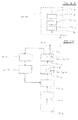
- Figure 4C shows a method for manufacturing a beam according to the invention and its preferred embodiments.
- a welding machine 4C-20 welds the seam of the beam.
- the energy input into the seam can be measured with a sensor 4C-30 connected to a measuring device 4C-6, and the sensor data may be fed into the measuring device and on to an adjusting device 4C-8.
- the readings of the adjusting device and measuring device can be read on a control panel 4C-10 that may also set control values for the adjusting device, measuring device, and welding machine.
- the energy input can be measured at the cross-section of the beam as a function of length at regular or irregular intervals at points L1, L2, L3, etc., where L represents a measure of length starting from zero and ending where the beam ends.
- Energy can be measured at the top and bottom seams of the middle web and/or top and bottom seams of the side webs.
- Each energy measurement can be registered automatically during manufacture and, thus, it is possible to send the data over Ethernet, for instance, to the reader, computer, or server where the data can be stored or processed. At least partly in response to this data, the warping of the beam may be prevented.
- the data can also be used in planning and dimensioning as cutting data of the plate and other corrective data, for instance.
- Each beam may contain an in-built jig and energy input measurements that follow the beam or beam component until the installation of the beam and rail beam can be stored therein.
- the data can also be considered part of the life cycle data of the product.
- energy input is measured as a function of length at four points simultaneously, and in the measurement one or more quantities are used or measured.
- Thermal energy input to the weld is calculated or derived from the measurement, the measured value is compared with a permanent or variable reference number and, on the basis of the comparison, the energy input to the weld is adjusted to make the energy input to each weld substantially equal.
- the plate parts required by the strength-wise optimized dimensioning of the rail beam are assembled together as a continuous process.
- the plate parts of the rail beam are located in storage or in a warehouse cut to size or in storage dimensions, and in disassembly and cutting devices.
- the control of the control apparatus or adjusting apparatus pre-sets the device to correspond to the dimensioning of the beam to be manufactured.
- the work cycle of the apparatus for manufacturing a beam begins. From the storage beams, the plate parts are transferred to assembly conveyors where they are assembled by means of pressure rolls to form a beam with a final cross-section. From the assembly conveyors, the beam proceeds to an assembly device where the seams of the separate plate parts are joined or brought together.
- the finished beam is transferred to a discharge conveyor.
- the beam is transferred from the discharge conveyor via a turning device and intermediate conveyor back to the assembly device.
- the apparatus may comprise two or more assembly devices, in which case the intermediate conveyor is not needed.
- the straightness of the beam is checked and the calibration done in a straightener to which the beam moves via a conveyor.
- the first assembly device may be arranged to weld the jig beam in the first step of the manufacture
- the second assembly device may be arranged to receive the jig beam and to weld the side web plates to the jig beam in the second step of the manufacture.
- the apparatus also comprises a straightener that is arranged to straighten flanges, and a bending device that is arranged to provide the curvature of the beam jig in a three-web beam or the middle web or the entire beam, if necessary.
- the manufacture of the beam may take place in two or more steps, in which one, two or more apparatuses may be used.
- the manufacture may be divided into different steps in such a manner that first, in the first step, an H beam with a middle web having a web plate and flanges, that is, a jig beam, is manufactured.
- both sides of the H beam have been welded, side plates are added on both sides of the H beam in the second step.
- the H beam may be run through the straightener for straightening the flanges in a third step.
- the curvature of the beam may be vertically and/or horizontally fine-adjusted and the beam checked and measured at a bending station in a fourth step.
- the manufacturing method and apparatus take into consideration, monitor and/or measure factors that affect one or more deformations of a beam part, beam or beam entity, and take any necessary action.
- the adjustments of the various factors affecting deformation can be done automatically or as a combination of automatic and manual straightening, and in manual straightening, the product is heated manually.
- the method and apparatus for manufacturing a beam comprise a control apparatus that performs the actual energy input measurement, for instance.
- the apparatus may comprise an automated deformation measuring system, in which the control system of the apparatus monitors the energy input to the welds of the products by each weld or weld group.
- the apparatus automatically adjusts and controls the energy input through each weld or weld group so as to minimize deformation in the product being manufactured and reduce the need for straightening.
- manufacture of the product is less expensive in factory scale.
- straightening merely by hand - as is done in the prior art - decreases the competitive advantages of a product made of steel in comparison with other materials, such as concrete, and is also an unreliable and uneconomical method.
- the method and system of the invention provide the advantage that it is possible to manufacture during the manufacturing process automatically a dimensionally accurate beam according to the specification, that is, a final product complying with the manufacturing tolerances.
- the method, apparatus, and beam of the invention and its preferred embodiments may be used for many different purposes, such as for manufacturing rail beams, for instance Maglev rail beams, or bridge structures.
Landscapes
- Engineering & Computer Science (AREA)
- Architecture (AREA)
- Civil Engineering (AREA)
- Structural Engineering (AREA)
- Mechanical Engineering (AREA)
- Electromagnetism (AREA)
- Physics & Mathematics (AREA)
- Life Sciences & Earth Sciences (AREA)
- Wood Science & Technology (AREA)
- Rod-Shaped Construction Members (AREA)
- Railway Tracks (AREA)
- Laser Beam Processing (AREA)
- Butt Welding And Welding Of Specific Article (AREA)
- Joining Of Building Structures In Genera (AREA)
Abstract
Description
- The invention relates to a beam, and especially to a rail beam, and to a method for its manufacture.
- A beam is a horizontal or inclined support used in construction engineering. The task of a beam in a structure is to support upper structures, such as floor slabs, roof, ceiling, bulkhead, bridge, road, or rails, for instance.
- In many applications, the beam has a precise specification, definition, and instructions according to which the beam is to be manufactured during the manufacturing phase. The manufacture of a steel rail beam of a train, for instance, has to be done manually. During manufacturing a positioning mould or fasteners or jig is/are made for the rail beam. However, a problem with the prior art is that the rail beam does not keep to the tolerances in the jig after manufacturing due to deformations caused by heat input directed to the seams of the beam during manufacturing.
- Thus, the beam does not meet the vertical tolerance, up/down tolerance and/or horizontal tolerance, left/right tolerance. A finished beam that is not according to the tolerances also cannot be straightened or made to comply with the specification afterward.
- It is thus an object of the invention to develop a beam, a method for manufacturing a beam, and an apparatus implementing the method in such a manner that the above-mentioned problems are solved. The object of the invention is achieved by a method and system which are characterized by what is disclosed in the independent claims. Preferred embodiments of the invention are disclosed in the dependent claims.
- The invention is based on the fact that the heat input used in manufacturing the beam is controlled and monitored centrally and, thus, the manufacturing tolerances are achieved by the method and apparatus of the invention and its preferred embodiments.
- The method and system of the invention provides the advantage that it is possible to manufacture during the manufacturing process automatically a dimensionally accurate beam according to the specification, that is, a final product complying with the manufacturing tolerances.
- The invention will now be described in greater detail by means of preferred embodiments with reference to the accompanying drawings, in which:
-
Figure 1 shows a first beam according to the invention and its preferred embodiments; -
Figure 2 shows a second beam according to the invention and its preferred embodiments; -
Figure 3 shows a third beam according to the invention and its preferred embodiments; -
Figure 4A shows a method for manufacturing a beam according to the invention and its preferred embodiments; -
Figure 4B shows a method for manufacturing a beam according to the invention and its preferred embodiments; and -
Figure 4C shows a method for manufacturing a beam according to the invention and its preferred embodiments. - The following description describes a steel rail beam of a magnetic train, and a method and apparatus for manufacturing a rail beam, but it should be understood that the beam can also be made of other materials or material combinations and that the beam of the invention and its preferred embodiments can also be used for many other purposes.
- In the description, a jig refers to the central web of the rail beam of the magnetic train, that is, the mould, positioning mould, or fasteners according to which or supported by which the beam or a part thereof can be made. A jig can also refer to the shape or mould of a three-web beam, to which the beam is set in a first step so as to make the rest of the beam in a second step. In the case of a three-web beam, for instance, the jig is formed in the first step and then used as support or mould in the second step of manufacturing the beam. The jig may be an H beam, H portion, or H jig that serves as a mould as the side plates are added. The central web may also be perforated. A jig may also refer to a jig built inside the beam. The central web may serve as the jig, and the jig may accompany the finished beam until its installation. The internal jig may be symmetric or asymmetric.
-
Figures 1 and 2 show the first and second beams according to the invention and its preferred embodiments. The beams have two horizontal plate-like parts or flanges and three vertical plate-like parts or webs: edge webs 1-2, 1-4 (Figure 1 ) and 2-2, 2-4 (Figure 2 ) and a third web or central web 1-6 (Figure 1 ) and 2-6 (Figure 2 ) between the edge webs. The webs can be joined at their first ends fixedly or detachably to a first horizontal plate-like part or flange, for instance bottom flange 1-10, 2-20 (Figures 1 and 2 ). The webs can be joined at their second, opposite ends fixedly or detachably to a second horizontal plate-like part or flange, for instance top flange 1-12, 2-12 (Figures 1 and 2 ). - The horizontal plate-like parts may be substantially parallel to each other, as shown in
Figures 1, 2 , and3 . All webs may be substantially parallel to each other, as shown inFigures 1 and 2 . The webs may be at a substantially perpendicular angle to the bottom flange and top flange. - The vertical parts are intended, among other things, to provide the structure with vertical rigidity and to transmit forces in the top flange to the bottom flange and through the bottom flange on to the next structural part, for example, that may be a foundation of a structure, structural part, or structural entity or another structure, or structural part, or beam. The horizontal parts are intended to provide the beam with horizontal rigidity.
- In
Figure 1 , the edge-most two webs are connected to opposite edges of the top flange. The first web 1-2 is, thus, connected to the top surface of the bottom flange and a first edge of the top flange, and the second web 1-4 is connected to the top surface of the bottom flange at a distance from the first and third webs and to a second edge of the top flange that is at the opposite end of the flange to the first edge of the flange. The middle, third web 1-6 is connected between the flanges at a distance from the edge-most webs. - In
Figure 2 , all three webs are connected entirely between the bottom and top flanges at a distance from each other, and the bottom and top flanges are at a distance from each other. Thus, the middle web plate may be connected entirely or partly between the bottom and top flanges and the middle web plate may reside at a distance from first and second side web plates. - In
Figure 3 , the edge-most two webs 3-2, 3-4 are also connected to opposite edges of the top flange 3-12. The first web 3-2 is then connected to the top surface of the bottom flange and the first edge of the top flange. The second web 3-4 is connected to the top surface of the bottom flange at a distance from the first web and to the second edge of the top flange that is at the opposite end of the flange to the first edge of the flange. The middle, third web 3-6 is connected between the flanges. InFigure 3 , the first web 3-2 is at an inclined position to the top and bottom flanges, at an angle α1 to the bottom flange, and the second web 3-4 is at another inclined position to the top and bottom flanges, at an angle α2 to the bottom flange. The inclination angle may be the same, as shown inFigure 3 , or different for both or all inclined webs. InFigure 3 , the middle web 3-6 is at a substantially perpendicular angle to the bottom and top flanges. - According to a preferred embodiment, the beam may be inclined at one or both ends. In such a case, one or more webs may be inclined or cut at an angle to the longitudinal direction of the beam, and the top or bottom flange may begin at a distance from the other flange. The web(s) may also be cut in such a manner that the desired end gradient is obtained.
- A beam according to the invention and its preferred embodiments may also comprise more or fewer than three vertical plate-like parts. There may also be more than two horizontal plate-like parts. The beam according to the invention and its preferred embodiments may also be used in another position than that shown in the figures, for instance in an upside down or slanted position.
- According to a preferred embodiment, two or more plate-like parts may be on top of each other or side by side against each other. Thus, the middle web, for instance, may have two plate-like parts joined together or one thicker plate-like part, the thickness of which may be approximately two or three times the thickness of the outer web, basic web or flange, for instance. One or more outer webs may also be thicker than the other plate-like parts. In addition or alternatively, the horizontal parts may either be substantially equal in thickness or one part may be thicker, for instance approximately two or three times thicker than the other web. According to yet another alternative, the top flange may be uniform in thickness or comprise two or more parts of different thicknesses. The same applies to the bottom flange and/or web.
- A structurally correct and accurately dimensioned beam should meet certain requirements. According to an alternative, the beam or beam profile of
Figure 1 should meet the conditions of the following model:
wherein HSDQ represents a dynamically loaded three-web Q casing, H is the total height of the web, bottom beam and top beam, d1 is the thickness of the edge plate, d2 is the thickness of the middle plate, t1 is the thickness of the top flange, t2 is the thickness of the bottom flange, B1 is the width of the top part of the profile or the width including the thicknesses of both edge plates, B2 is the width of the bottom flange or the width of the bottom part of the profile or the width of the profile, and L is the length of the top flange and bottom flange or profile. The beam may also be called a casing. Dynamic load refers to the fact that, in addition to the static load used in conventional construction, the beam withstands traffic loads, earthquake loads, impacts, etc. A beam withstanding dynamic loads withstands a moving load better than a construction beam dimensioned for static load. A beam according to the invention and its preferred embodiment may withstand static and/or dynamic loads. - According to an alternative, the beam or beam profile of
Figure 2 should meet the conditions of the following model:
wherein HSDK represents a dynamically loaded three-web K casing, H is the total height of the web, bottom beam and top beam or the height of the profile from the bottom surface of the bottom flange to the top surface of the top flange, d1 is the thickness of the edge plate, d2 is the thickness of the middle plate, t1 is the thickness of the top flange, t2 is the thickness of the bottom flange, B1 is the width of the top part of the profile or the width of the top flange, B2 is the width of the bottom flange or the width of the bottom part of the profile or the width of the profile, and L is the length of the top flange and bottom flange and web or profile. - According to an alternative, the beam or beam profile of
Figure 3 should meet the conditions of the following model:
wherein HSDA represents a dynamically loaded three-web slant-webbed A casing, H is the total height of the middle web, bottom beam and top beam or the height of the profile from the bottom surface of the bottom flange to the top surface of the top flange, d1 is the thickness of both edge plates, d2 is the thickness of the middle plate, t1 is the thickness of the top flange, t2 is the thickness of the bottom flange, B1 is the width of the top flange including the thicknesses of both edge plates, or the width of the top part of the profile, B2 is the width of the bottom flange or the width of the bottom part of the profile, and L is the length of the bottom flange and top flange and web or profile. - In
Figure 1 , the height H of the beam from the bottom flange to the top flange may be 250 mm ... 3000 mm. The thickness t1 of the top flange and the thickness t2 of the bottom flange may be 6 mm ... 60 mm. The width B2 of the bottom flange may be 290 mm ... 3000 mm. The thickness of webs d1 and d2 may be 5 mm ... 20 mm. The width B1 of the top part of the beam, including the thicknesses of the edge-most webs inFigure 1 , may be 250 mm ...2800 mm. - In
Figure 2 , the height H of the beam from the bottom flange to the top flange may be 250 mm ... 5000 mm. The thickness t1 of the top flange and the thickness t2 of the bottom flange may be 8 mm ... 100 mm. The width B2 of the bottom flange may be 250 mm ... 2000 mm. The thickness of webs d1 and d2 may be 5 mm ... 30 mm. The width B1 of the top part of the beam may be 250 mm ... 2000 mm. - In
Figure 3 , the height H of the beam from the bottom flange to the top flange may be 300 mm ... 3000 mm. The thickness t1 of the top flange and the thickness t2 of the bottom flange may be 8 mm ... 60 mm. The width B2 of the bottom flange may be 500 mm ... 3000 mm. The thickness d1, d2 of the webs may be 5 mm ... 20 mm. The width B1 of the top part of the beam, including the thicknesses of the edge-most webs inFigure 3 , may be 250 mm ...1500 mm. The angle α1, α2 between the edge-most webs and the bottom beam may be larger than or equal to 45 degrees, but smaller than 90 degrees, such as 50, 60, 66, 75, 80, or 85 degrees. - The length L of the beam may in all cases be 5 m, 16 m, 32 m, 50 m, or 64 m, for example. The length of the beam may be optimized to be as long as possible in such a manner that the curvature properties of the beam remain within tolerances.
- The vertical plate-like parts can be fastened, connected, or joined to the edges or surfaces, such as top surface and bottom surface, of the horizontal plate-like parts. The vertical plate-like parts can thus be connected entirely between the bottom and top flanges, for instance. Alternatively, one or more webs can be connected to the edge of either flange. The webs can also be arranged in various tilted positions. The structure of the invention and its preferred embodiments can be said to be a casing structure which is a very bearing structure.
- Joining the plate-like parts together may take place in many different ways. Connecting the webs to the flanges, the flanges to the webs, or one beam to another to form a beam entity may take place by welding or soldering, for instance.
- According to the invention and its preferred embodiments, it is possible to affect the size, thickness, flatness, surface quality, and structural strength of a piece, for example, and all these properties may be made suitable according to the final specifications. In manufacturing where metal is rolled, a piece of metal is run between rolls of a rolling mill to modify the metal to a required form.
- In welding, two or more pieces or parts thereof are joined together by utilizing heat and/or compression in such a manner that the pieces or parts thereof form a continuous connection. In welding, it is possible to use several different heat sources, such as electric current, heat due to friction, flame, laser beam or electron beam, or a combination thereof. Welding may thus be laser welding, for instance. An additional material with a melting point nearly the same as that of the basic material may be used in welding.
- When joining two or more pieces or parts thereof together by soldering, only the soldering material or joining material melts, and the pieces being joined together do not.
- The beam and the plate-like parts can be made of one or more parts. The beam and the plate-like parts may comprise one or more materials. The may be made of aluminium, steel, alloy, thermoplastic, concrete, wood, or a combination thereof. The beam may also be partly or entirely transparent. The beam or plate-like parts may have one or more openings for adjusting the bearing value of the structure or enabling lead-throughs, for instance.
-
Figure 1 shows eight welds. The middle web may be connected with four welds, of which two 1-21, 1-22 are at the bottom flange and two 1-25, 1-26 at the top flange. In addition, the edge webs may be connected to the bottom flange with one or more welds 1-23, 1-24, and to the top flange with one or more welds. -
Figure 2 shows eight welds. The middle web may be connected with four welds, of which two 2-21, 2-22 are at the bottom flange and two 2-25, 2-26 at the top flange. In addition, the edge webs may be connected to the bottom flange with one or more welds 2-23, 2-24, and to the top flange with one or more welds 2-27, 2-28. -
Figure 3 shows eight welds. The middle web may be connected with four welds, of which two 3-21, 3-22 are at the bottom flange and two 3-25, 3-26 at the top flange. In addition, the edge webs may be connected to the bottom flange with one or more welds 3-23, 3-24, and to the top flange with one or more welds. The welds may be made to extend from the angle formed by the plate parts being joined together. Alternatively, grooves may be formed for the seams to be filled by welding. - In joining, as in welding, two or more seams may be welded substantially simultaneously. According to a preferred embodiment, two or four seams are welded or otherwise joined together substantially simultaneously. The seams may also be welded using the method at different times, alternately or partly alternately in accordance with the technical tolerance requirements of the rail beam.
- When joining plate-like parts together by welding, the welding point(s) generate energy through the welding blowpipe to the welding site and seam. This energy and/or other measurable quantities may be measured from each seam or from one or more welding points of a seam, for instance. It is then possible to measure during joining, during welding or in connection with welding, the energy input to the seam or the joining point of parts being connected, or used in welding or joining the beam parts, the energy generation value, or a quantity directly or inversely proportional to the input energy. The measured value may be the input heat or energy per unit of length, for example. Thus, the value may be kJ/mm, for instance.
- The measured value, energy or energy amount may be compared with one or more reference values. At least partly in response to the comparison, it is possible to calculate or otherwise define a new or subsequent value for the energy amount to be input to the joining point. In other words, in response to measuring the amount of energy input to the joining point and/or used in joining, the amount of energy input to the joining point is adjusted. The latter value may be the same as or different than the former value.
- In the manufacturing method of the rail beam, it is possible to use in energy measurement, among other things, a measured welding current, voltage, arc voltage, current type, temperature, transport rate, and velocity, from which thermal energy can be calculated or derived using selected values. Of these, it is possible to measure one, two or four quantities at a time at one, preferably four, locations or points. The measuring apparatus is placed in the assembly device or in connection with it. It is also possible to set one or more limit values or initial values for these quantities.
- For instance, in manufacturing a rail beam of a magnetic train, the tolerance must be precise, and the train must not derail or take off from the rail. In such a case, one important manufacturing criterion of the beam is the vertical curvature tolerance that can be measured and compensated for, and the beam manufactured accurately in accordance with the invention and its preferred embodiments, whereby the problem of the warping of the beam can be solved. It should be noted that on a magnetic railway, the speed of the train may be 500 km/h or more.
- In the assembly apparatus, the values of the welding parameters can be read on the control panel during welding and also used for measuring the energy of heat input. In other words, the input of thermal energy can be measured and the allowed and selected values monitored and read on the measuring display for each weld in the system of the assembly apparatus.
- When the parameter values are changed, it is possible by means of thermal energy to synchronize the warping of the beam by welding points during the manufacture. Input of thermal energy can also be measured with separate sensors. The assembly apparatus may compare a signal received from a sensor with one or more predefined threshold values or limit values and/or another measuring value, and adjust the energy or power being supplied on the basis of the measurement and comparison. By means of the control value received from the apparatus, it is possible to control the manufacture of a rail beam in the system according to the tolerance requirements of the rail beam. The value of the energy supplied to the seam or the maximum value of heat input can be obtained from the material specifications of the beam material supplier, such as from the values provided by steel suppliers for different steel grades.
- The energy value input to each seam or part thereof can, thus, be measured and adjusted individually. Alternatively, the adjustment may be substantially simultaneous and/or equivalent. For instance, it is possible to use an energy input synchronization device or measuring system of the assembly apparatus to measure that the same amount of energy is input to each seam. This way, the parts to be joined to the beam or the section of the beam to be seamed are kept substantially straight or at a required straightness or curvature.
- The energy input measuring apparatus is a system in the method of the invention and is, thus, adapted to control the amount of energy input to the seam in all or some of the seams. The apparatus is also adapted to keep the energy values exactly the same or substantially the same. According to an alternative embodiment, the energy amount input to the seams is substantially the same in one entire seam but different in value than in at least one other entire seam or part thereof.
- Seam-specific parameter information may be provided for different seams for controlling the method and for the measurement received through sensors. Cutting parameters of the plates that may affect the shape of the beam by causing warping, for instance, may be used as these factors. The warping may be compensated or it may be caused by a controlled energy input synchronization device in the method for manufacturing a beam and rail beam.
- As stated above, according to the invention and its preferred embodiments, the beam comprises at least two webs that are connected to a bottom flange and a top flange. In the method for manufacturing a beam, a beam part is transferred from
storage 4B-2 to acutting apparatus 4B-4 that cuts the plate parts of the beam to specific dimensions, and the plate parts cut to size are transferred to anassembly conveyor 4B-6. After this, at least two plate parts of a beam are set together by means of pressure rolls of theassembly conveyor 4B-6 to form a beam with a final cross-section. The beam parts set together are moved with the assembly conveyor to anassembly device 4B-8. - In the first step of manufacturing a beam, the assembly device is arranged to connect the middle web plate of the beam to the bottom and top flanges to form a jig beam 4C-2 (
Figure 4C ). The connection may take place by supporting or welding the middle web plate at least at one point to the bottom flange and at least at one point to the top flange. In the second step of manufacturing a beam, the assembly device is arranged to connect to the first edge of the jig beam a first side web plate and at a distance from the first side web plate to the opposite, second edge of the jig plate a second web plate by supporting or welding, and both the first and second side web plates on at least one side to the bottom and top flanges. Welding may be done by a welding machine 4C-20 in the assembly device or connected thereto. - The beam formed in the first step is moved from the
assembly device 4B-8 to adischarge conveyor 4B-10. The formed beam or part thereof is moved 4A-1 to acontrol apparatus 4A-2 that checks the shape of the beam made in the first step, such as the straightness and tolerance deviations of the plate parts and the entire unit. - An arrangement for manufacturing a beam may comprise a straightener and a bending device. The straightener may be arranged to straighten the flanges and the bending device may be arranged to bend the curvature of the beam jig, that is, the middle web and the entire beam in a three-web beam. When the middle web beam - for instance an H beam with a web plate and flanges - has been made and both of its sides welded, side plates are added to both sides. However, the beam may be run through the straightener before adding the side plates. When the side plates have also been added to the beam, the curvature of the entire beam may be vertically and/or horizontally fine-adjusted and the beam checked and measured at a bending station.
- If the result of the check-up from the control apparatus, such as the straightness value or tolerance deviations, is not within predefined limit values, the beam formed in the first step is fed to the
straightener 4A-4 to straighten the part exceeding the limit value with hydraulic presses of the device and/or to thebending device 4A-6 to bend the part exceeding the limit value with hydraulic presses of the device. - The calibration of the beam by 3-dimensional laser measurement, for instance, can also be done in the
straightener 4A-4. The middle web beam can, thus, be run through the straightener, because heat may bend the plates, flanges or webs. Especially wide plates, such as the top flange, may bend. After the straightener, the piece may be transferred to the bending device, where it is forced by repeated bendings to an exact size and shape. This process can be done for instance after all four welds of the middle web beam have been welded or all eight welds of the entire piece have been welded. The straightness and/or curvature can be measured by laser measuring to immediately find out whether the piece is within tolerances, that is, as straight and curved as planned, or will the beam or piece need to be pressed to become slightly warped, over-curved or under-curved. For instance, a piece can be made straight or warped with an internal jig. - After this, the beam made in the first step is transferred from the
discharge conveyor 4B-10 to aturning device 4B-12 to turn the beam or part thereof, such as jig beam. The beam may be turned by the turning device for connecting repeated seams, and it may be turned 180 degrees, for example. From the turning device, the element is moved to a return conveyor orintermediate conveyor 4B-14 and on back to theassembly conveyor 4B-6. - In the second step of assembly, the next beam part or the rest of the plate parts of the beam or side webs are set together by means of pressure rolls of the
assembly conveyor 4B-6 to form a beam with a final cross-section. The entire beam is transferred by theassembly conveyor 4B-6 to anassembly apparatus 4B-8 where the seams of the parts set together are supported or welded by a welding machine 4C-20 of the assembly device in the second step of manufacturing the beam. - The beam part or entire beam formed in the second step can also be moved after welding to the control apparatus, straightener and bending device to measure, determine, and repair one or more shapes, straightness, or tolerance deviations.
- In other words, the method for manufacturing a beam may comprise the steps of: cutting the plates with a
cutting apparatus 4B-4, transferring the plates cut to size to anassembly conveyor 4B-6 and on to afirst assembly apparatus 4B-8, assembling the beam of plates with the first assembly apparatus that comprises joining the pressed plate parts together and an energy input measurement and control apparatus anddischarge side conveyors 4B-10 having acontrol apparatus 4A-2 for beam tolerance deviations, turning the beam for joining repeated seams with aturning device 4B-12, and transferring the beam back to the first assembly apparatus with areturn conveyor 4B-14 for joining the next seam of the beam and assembling the existing beam. After this, the assembled jig beam is transferred to asecond assembly apparatus 4B-8 that comprises joining the pressed side plates together, an energy input measurement and control apparatus and discharge side conveyors that may also contain a control apparatus for tolerance deviations. If necessary, the beam may be transferred to astraightener 4A-4 andbending device 4A-6 for calibration. A control apparatus 4C-1 0 or adjusting device 4C-8 may be used to control the energy input measurement and control, the control apparatus for beam tolerance deviations, the straightener and/or bending device. - The assembly apparatus may control and monitor the manufacture of the internal jig. Energy input may be controlled in a centralized and seam-specific manner with an energy input synchronization apparatus or control apparatus.
- As described above, in the first step, the first part of the beam, H beam or I beam, may be assembled to form the jig beam and, in the second step, side plates may be added to this H beam or I beam. In the first step, the middle web may be welded with two seams to the bottom plate and with two seams to the top plate, that is, in total with four seams, and in the second step, the side webs may be welded with one or two seams to the bottom plate and one or two seams to the top plate. At the first welding station, the entire middle web may be welded on both sides, and after the straightener, at the second welding station, the side webs may be welded to the H beam. After both sides have been run on the second machine, the rail beam comprises eight seams. The rail beam may alternatively comprise a different number of welds than eight, for instance six, ten, or twelve welds. The rail beam may thus comprise at least eight welds, for instance.
- For instance in manufacturing a slant-webbed casing beam, it is possible to make the I beam in the first step and then measure the straightness and make corrections, if necessary. In the second step, the slant-webbed plates and backings may be added on both sides by assembling tack welding, for example. The bevels of the casing may be welded full to comply with rivet welding requirements, and finally the straightness of the casing may be measured.
- The assembly apparatus, straightener, bending device and/or adjusting apparatus, for example, may be arranged to take into consideration various factors that affect the shape of the beam. These factors may be ones affecting the shape before, during, and after welding, or combinations thereof.
- The control panel of the apparatus may comprise display devices that display measuring information, data, and information received from each seam, and control information transmitted to each seam.
- By taking into consideration the energy values input in the seams, the vertical and/or horizontal curvature may be taken into account in the manufacture of the beam. During the manufacture, it is also possible to take into consideration the deformation of the beam that takes place over time or due to temperature. The different changes and curvatures may be compensated during manufacture by increasing or decreasing energy input to one or more seams or parts thereof. When manufacturing a beam for a magnetic railway, especially the vertical curvature and bending should be taken into account. One or more limit values or initial values may be given to said changes and vertical and horizontal curvatures.
-
Figure 4C shows a method for manufacturing a beam according to the invention and its preferred embodiments. In it, a welding machine 4C-20 welds the seam of the beam. The energy input into the seam can be measured with a sensor 4C-30 connected to a measuring device 4C-6, and the sensor data may be fed into the measuring device and on to an adjusting device 4C-8. The readings of the adjusting device and measuring device can be read on a control panel 4C-10 that may also set control values for the adjusting device, measuring device, and welding machine. - In measuring the energy input to the seam in the manufacturing method of a beam and rail beam, the energy input can be measured at the cross-section of the beam as a function of length at regular or irregular intervals at points L1, L2, L3, etc., where L represents a measure of length starting from zero and ending where the beam ends. Energy can be measured at the top and bottom seams of the middle web and/or top and bottom seams of the side webs. Each energy measurement can be registered automatically during manufacture and, thus, it is possible to send the data over Ethernet, for instance, to the reader, computer, or server where the data can be stored or processed. At least partly in response to this data, the warping of the beam may be prevented. The data can also be used in planning and dimensioning as cutting data of the plate and other corrective data, for instance. Each beam may contain an in-built jig and energy input measurements that follow the beam or beam component until the installation of the beam and rail beam can be stored therein. The data can also be considered part of the life cycle data of the product.
- According to a preferred embodiment, energy input is measured as a function of length at four points simultaneously, and in the measurement one or more quantities are used or measured. Thermal energy input to the weld is calculated or derived from the measurement, the measured value is compared with a permanent or variable reference number and, on the basis of the comparison, the energy input to the weld is adjusted to make the energy input to each weld substantially equal.
- When manufacturing or making a beam or beam entity of the invention and its preferred embodiments, the plate parts required by the strength-wise optimized dimensioning of the rail beam are assembled together as a continuous process. In the apparatus, the plate parts of the rail beam are located in storage or in a warehouse cut to size or in storage dimensions, and in disassembly and cutting devices. The control of the control apparatus or adjusting apparatus pre-sets the device to correspond to the dimensioning of the beam to be manufactured. After start-up, the work cycle of the apparatus for manufacturing a beam begins. From the storage beams, the plate parts are transferred to assembly conveyors where they are assembled by means of pressure rolls to form a beam with a final cross-section. From the assembly conveyors, the beam proceeds to an assembly device where the seams of the separate plate parts are joined or brought together. The finished beam is transferred to a discharge conveyor.
- If the manufacture of the beam requires further processing, the beam is transferred from the discharge conveyor via a turning device and intermediate conveyor back to the assembly device. The apparatus may comprise two or more assembly devices, in which case the intermediate conveyor is not needed. The straightness of the beam is checked and the calibration done in a straightener to which the beam moves via a conveyor.
- The first assembly device may be arranged to weld the jig beam in the first step of the manufacture, and the second assembly device may be arranged to receive the jig beam and to weld the side web plates to the jig beam in the second step of the manufacture. Thus, there may be one assembly device line for manufacturing the middle web and another or more lines for joining the side plates to the beam with a middle web. All these devices or lines may have a measuring, monitoring, and control apparatus for heat input or energy input so as to be able to take into consideration possible changes in the curvature of the beam or to cause changes knowingly in the beam or its curvature. The tolerances of the beam can thus be monitored in such a manner that energy input into each weld is the same and/or as required.
- Thus, the apparatus also comprises a straightener that is arranged to straighten flanges, and a bending device that is arranged to provide the curvature of the beam jig in a three-web beam or the middle web or the entire beam, if necessary.
- The manufacture of the beam may take place in two or more steps, in which one, two or more apparatuses may be used. The manufacture may be divided into different steps in such a manner that first, in the first step, an H beam with a middle web having a web plate and flanges, that is, a jig beam, is manufactured. When both sides of the H beam have been welded, side plates are added on both sides of the H beam in the second step. However, before the step of adding the side plates to the beam, the H beam may be run through the straightener for straightening the flanges in a third step. When all side plates, that is, side webs, have been added to the beam, the curvature of the beam may be vertically and/or horizontally fine-adjusted and the beam checked and measured at a bending station in a fourth step.
- According to the invention and its preferred embodiments, the manufacturing method and apparatus take into consideration, monitor and/or measure factors that affect one or more deformations of a beam part, beam or beam entity, and take any necessary action. The adjustments of the various factors affecting deformation can be done automatically or as a combination of automatic and manual straightening, and in manual straightening, the product is heated manually. For this purpose, the method and apparatus for manufacturing a beam comprise a control apparatus that performs the actual energy input measurement, for instance. Thus, the apparatus may comprise an automated deformation measuring system, in which the control system of the apparatus monitors the energy input to the welds of the products by each weld or weld group. The apparatus automatically adjusts and controls the energy input through each weld or weld group so as to minimize deformation in the product being manufactured and reduce the need for straightening. In addition, the manufacture of the product is less expensive in factory scale. However, it should be noted that straightening merely by hand - as is done in the prior art - decreases the competitive advantages of a product made of steel in comparison with other materials, such as concrete, and is also an unreliable and uneconomical method.
- The method and system of the invention provide the advantage that it is possible to manufacture during the manufacturing process automatically a dimensionally accurate beam according to the specification, that is, a final product complying with the manufacturing tolerances. The method, apparatus, and beam of the invention and its preferred embodiments may be used for many different purposes, such as for manufacturing rail beams, for instance Maglev rail beams, or bridge structures.
- It is obvious to a person skilled in the art that, as technology advances, the basic idea of the invention may be implemented in many different ways. The invention and its embodiments are thus not restricted to the examples described above, but may vary within the scope of the claims.
Claims (18)
- A beam (1-1, 2-1, 3-1), characterised in that it comprises at least three web plates (1-2, 1-4, 1-6, 2-2, 2-4, 2-6, 3-2, 3-4, 3-6) that are connected to a bottom flange (1-10, 1-12, 2-10, 2-12, 3-10, 3-12) and top flange (1-10, 1-12, 2-10, 2-12, 3-10, 3-12).
- A beam (1-1, 2-1, 3-1) as claimed in claim 1, characteri s e d in that at least one side web plate (1-2, 1-4, 2-2, 2-4, 3-2, 3-4) is connected to the top surface of the bottom flange (1-10, 1-12, 2-10, 2-12, 3-10, 3-12) and to the bottom surface of the top flange (1-10, 1-12, 2-10, 2-12, 3-10, 3-12) or to the edge of the top flange (1-10, 1-12, 2-10, 2-12, 3-10, 3-12).
- A beam (1-1, 2-1, 3-1) as claimed in claim 1 or 2, characteri s e d in that at least one side web plate (1-2, 1-4, 2-2, 2-4, 3-2, 3-4) is in a slanted position to the bottom flange (1-10, 1-12, 2-10, 2-12, 3-10, 3-12) and to the top flange (1-10, 1-12, 2-10, 2-12, 3-10, 3-12).
- A beam (1-1, 2-1, 3-1) as claimed in any one of claims 1 to 3, characterised in that the beam (1-1, 2-1, 3-1) comprises on the middle web an in-built jig.
- A beam (1-1, 2-1, 3-1) as claimed in any one of claims 1 to 4, characterised in that the beam (1-1, 2-1, 3-1) has at least eight automatically formed welds.
- A beam (1-1, 2-1, 3-1) as claimed in any one of claims 1 to 5, c h a r a c t e r i s e d in that the length of the beam is approximately 5 m, 6 m, 10 m,12 m,16 m,32 m,50 m, or 64m.
- A method for manufacturing a beam (1-1, 2-1, 3-1), comprising:connecting in the first step of manufacturing the beam (1-1, 2-1, 3-1), a middle web plate (1-6, 2-6, 3-6) to the bottom flange (1-10, 1-12, 2-10, 2-12, 3-10, 3-12) and top flange (1-10, 1-12, 2-10, 2-12, 3-10, 3-12) to form a jig beam by welding the middle web plate at least at one point (1-21, 1-22, 2-21, 2-22, 3-21, 3-22) to the bottom flange (1-10, 1-12, 2-10, 2-12, 3-10, 3-12) and at least at one point to the top flange (1-10, 1-12, 2-10, 2-12, 3-10, 3-12);connecting in the second step of manufacturing the beam (1-1, 2-1, 3-1) a first side web plate (1-2, 1-4, 2-2, 2-4, 3-2, 3-4) to a first edge of the jig beam, and at a distance from the first side web plate (1-2, 1-4, 2-2, 2-4, 3-2, 3-4) on the opposite, second edge of the beam (1-1, 2-1, 3-1) a second side web plate (1-2, 1-4, 2-2, 2-4, 3-2, 3-4) by welding, and both the first side web plate (1-2, 1-4, 2-2, 2-4, 3-2, 3-4) and second side web plate (1-2, 1-4, 2-2, 2-4, 3-2, 3-4) at least at one point to the bottom flange (1-10, 1-12, 2-10, 2-12, 3-10, 3-12) and top flange (1-10, 1-12, 2-10, 2-12, 3-10, 3-12);measuring the energy input into the joining point (1-21, 1-22, 1-23, 1-24, 1-25, 1-26, 2-21, 2-22, 2-23, 2-24, 2-25, 2-26, 3-21, 3-22, 3-23, 3-24, 3-25, 3-26) of the parts being connected; andusing the value obtained during the energy measurement to adjust the amount of energy input to the joining point during the connection and after the measurement.
- A method as claimed in claim 7, characterised by comparing the measured energy with one or more predefined limit values and decreasing the amount of energy input to the joining point (1-21, 1-22, 1-23, 1-24, 1-25, 1-26, 2-21, 2-22, 2-23, 2-24, 2-25, 2-26, 3-21, 3-22, 3-23, 3-24, 3-25, 3-26), if the measured energy amount exceeds the predefined limit value, and increasing the amount of energy input to the joining point (1-21, 1-22, 1-23, 1-24, 1-25, 1-26, 2-21, 2-22, 2-23, 2-24, 2-25, 2-26, 3-21, 3-22, 3-23, 3-24, 3-25, 3-26), if the measured energy amount is below the predefined limit value.
- A method as claimed in claim 8, characterised by measuring the horizontal and/or vertical curvature of the beam (1-1, 2-1, 3-1) parts or the entire beam (1-1, 2-1, 3-1), and calculating at least partly in response to the measured curvature said one or more limit values.
- A method as claimed in any one of claims 7 to 9, characterised by measuring the energy input into the joining point (1-21, 1-22, 1-23, 1-24, 1-25, 1-26, 2-21, 2-22, 2-23, 2-24, 2-25, 2-26, 3-21, 3-22, 3-23, 3-24, 3-25, 3-26) of the parts being connected in the cross-section of the beam (1-1, 2-1, 3-1) as a function of length.
- A method as claimed in any one of claims 7 to 10, characterised by connecting the middle web plate (1-6, 2-6, 3-6) by welding it on both sides to the bottom flange (1-10, 1-12, 2-10, 2-12, 3-10, 3-12) and on both sides to the top flange (1-10, 1-12, 2-10, 2-12, 3-10, 3-12), and the four welds are done substantially simultaneously.
- A method as claimed in any one of claims 7 to 11, characterised by connecting the side web plates by welding with one or two seams (1-2, 1-4, 2-2, 2-4, 3-2, 3-4) to both the bottom flange (1-10, 1-12, 2-10, 2-12, 3-10, 3-12) and top flange, and the four welds are done substantially simultaneously.
- A method as claimed in any one of claims 7 to 12, characterised by straightening before or after the first step of manufacturing the beam (1-1, 2-1, 3-1) at least one of the flanges in the straightener before connecting the side web plates (1-2, 1-4, 2-2, 2-4, 3-2, 3-4) to the jig beam.
- A method as claimed in any one of claims 7 to 13, characterised by measuring after the first step of manufacturing the beam (1-1, 2-1, 3-1) the vertical and/or horizontal curvature of the jig beam; and
if it/they deviate from one or more pre-set limit values, fine-adjusting the vertical and/or horizontal curvature of the jig beam by means of pressure rolls of a discharge conveyor. - A system for manufacturing a beam (1-1, 2-1, 3-1), comprising:an assembly conveyor (4B-6) that receives at least two beam parts, sets them together by means of pressure rolls of the assembly conveyor (4B-6) to form a beam with a final cross-section, and transfers the joined beam parts to an assembly device (4B-8);an assembly device (4B-8) which receives the joined beam parts and which assembly device (4B-8) comprises:a welding machine (4C-20) that welds together the joined beam (1-1, 2-1, 3-1) parts by welding in the first step of the manufacture the middle web plate at least at one point (1-21, 1-22, 2-21, 2-22, 3-21, 3-22) to the bottom flange, and at least at one point (1-21, 1-22, 2-21, 2-22, 3-21, 3-22) to the top flange to form a jig beam, and by welding in the second step of manufacturing the beam (1-1, 2-1, 3-1) a first side web plate (1-2, 1-4, 2-2, 2-4, 3-2, 3-4) to the first edge of the jig beam, and at a distance from the first side web plate (1-2, 1-4, 2-2, 2-4, 3-2, 3-4), to the opposite, second edge a second side web plate (1-2, 1-4, 2-2, 2-4, 3-2, 3-4) by welding both the first side web plate (1-2, 1-4, 2-2, 2-4, 3-2, 3-4) and the second side web plate (1-2, 1-4, 2-2, 2-4, 3-2, 3-4) on at least one side to the bottom flange (1-10, 1-12, 2-10, 2-12, 3-10, 3-12) and top flange (1-10, 1-12, 2-10, 2-12, 3-10, 3-12).an energy measuring device that measures the energy input into the joining point (1-21, 1-22, 1-23, 1-24, 1-25, 1-26, 2-21, 2-22, 2-23, 2-24, 2-25, 2-26, 3-21, 3-22, 3-23, 3-24, 3-25, 3-26) of the parts being connected during the joining and transmits the measured energy amount to an adjusting device (4C-8);an adjusting device (4C-8) that receives from the energy measuring device (4C-6) the measured energy amount, calculates the energy amount to be input into the joining point of the parts being welded at least partly on the basis of the measured energy amount, and transmits the calculated energy amount to be used in welding to the welding machine (4C-20).
- A system as claimed in claim 15, characterised in that it also comprises:a turning device (4B-12) that receives from the assembly device (4B-8) a beam or part thereof, such as jig beam, turns it and feeds it back to the assembly conveyor (4B-6) for a second step of welding the beam.
- A system as claimed in claim 15 or 16, characterised in that it also comprises:a straightener (4A-4) for straightening the beam (1-1, 2-1, 3-1) or part thereof; anda bending device (4A-6) for bending the beam (1-1, 2-1, 3-1) or part thereof.
- A system as claimed in any one of claims 15 to 17, characterised in that the system also comprises two assembly devices (4B-8), the first assembly device being arranged to weld the jig beam in the first step of the manufacture, and the second assembly device being arranged to receive the jig beam and to weld the side web plates to the jig beam in the second step of the manufacture.
Priority Applications (12)
| Application Number | Priority Date | Filing Date | Title |
|---|---|---|---|
| EP11157809.2A EP2497581B1 (en) | 2011-03-11 | 2011-03-11 | Steel rail beam for a magnetic train, method and system for manufacturing such beam |
| US13/113,194 US8517247B2 (en) | 2011-03-11 | 2011-05-23 | Method for manufacturing beam, and beam |
| RU2013127686/03A RU2600244C2 (en) | 2011-03-11 | 2011-05-31 | Method and system for making beam |
| RU2011122115/03A RU2011122115A (en) | 2011-03-11 | 2011-05-31 | BEAM, METHOD AND SYSTEM FOR ITS MANUFACTURE |
| CL2012000624A CL2012000624A1 (en) | 2011-03-11 | 2012-03-09 | Beam comprising at least one core or central plate, a first edge plate and a second edge plate that are connected to a lower wing and an upper wing, because the central plate is connected by continuous welding in the lower wing, with two continuous welds on the upper wing, and the first edge plate is connected to the surface of the lower wing with one or two welds. |
| JP2012054902A JP2012188919A (en) | 2011-03-11 | 2012-03-12 | Method for manufacturing beam, and beam |
| US13/974,934 US8910848B2 (en) | 2011-03-11 | 2013-08-23 | Method for manufacturing beam, and beam |
| JP2014021504A JP5931938B2 (en) | 2011-03-11 | 2014-02-06 | Method and beam for manufacturing a beam |
| RU2014130791A RU2014130791A (en) | 2011-03-11 | 2014-07-24 | BEAM, METHOD AND SYSTEM FOR ITS MANUFACTURE |
| CL2015001372A CL2015001372A1 (en) | 2011-03-11 | 2015-05-20 | Method for the manufacture of a beam where the heat input during manufacturing is controlled to avoid deformations comprises connecting in the first stage of manufacturing the beam a central core plate to the lower wing and the upper wing to form a pattern beam by middle of the plate soldier; and system to manufacture a beam. (divisional of application 624-2012). |
| JP2015117550A JP6125569B2 (en) | 2011-03-11 | 2015-06-10 | Method and beam for manufacturing a beam |
| JP2017075323A JP2017198061A (en) | 2011-03-11 | 2017-04-05 | Method for manufacturing beam, and beam |
Applications Claiming Priority (1)
| Application Number | Priority Date | Filing Date | Title |
|---|---|---|---|
| EP11157809.2A EP2497581B1 (en) | 2011-03-11 | 2011-03-11 | Steel rail beam for a magnetic train, method and system for manufacturing such beam |
Publications (2)
| Publication Number | Publication Date |
|---|---|
| EP2497581A1 true EP2497581A1 (en) | 2012-09-12 |
| EP2497581B1 EP2497581B1 (en) | 2022-09-21 |
Family
ID=44117303
Family Applications (1)
| Application Number | Title | Priority Date | Filing Date |
|---|---|---|---|
| EP11157809.2A Active EP2497581B1 (en) | 2011-03-11 | 2011-03-11 | Steel rail beam for a magnetic train, method and system for manufacturing such beam |
Country Status (5)
| Country | Link |
|---|---|
| US (2) | US8517247B2 (en) |
| EP (1) | EP2497581B1 (en) |
| JP (4) | JP2012188919A (en) |
| CL (2) | CL2012000624A1 (en) |
| RU (3) | RU2011122115A (en) |
Cited By (2)
| Publication number | Priority date | Publication date | Assignee | Title |
|---|---|---|---|---|
| CN114193635A (en) * | 2021-12-23 | 2022-03-18 | 国泰新点软件股份有限公司 | Method and device for cutting beam in building engineering |
| CN115847179A (en) * | 2022-12-16 | 2023-03-28 | 雷沃工程机械集团有限公司 | Flatness processing control method for excavator rotating platform assembly |
Families Citing this family (9)
| Publication number | Priority date | Publication date | Assignee | Title |
|---|---|---|---|---|
| CN103018021B (en) * | 2012-11-29 | 2014-12-31 | 中国电力科学研究院 | Assembled steel girder and power-transmission steel pipe pole structure assembly provided with same |
| US10087628B2 (en) * | 2015-07-05 | 2018-10-02 | Constantine Shuhaibar | Structural system and method using monolithic beams having improved strength |
| US9809978B2 (en) * | 2015-07-05 | 2017-11-07 | Constantine Shuhaibar | Structural system and method using monolithic beams having improved strength |
| US10807662B2 (en) * | 2017-11-20 | 2020-10-20 | Ford Global Technologies, Llc | Method of producing a cross car beam utilizing net, form and pierce technology |
| CN109056432B (en) * | 2018-10-12 | 2023-09-22 | 中铁二院工程集团有限责任公司 | Rigidity-adjustable track beam structure and magnetic levitation track test line |
| CN111571072A (en) * | 2020-05-28 | 2020-08-25 | 上海外高桥造船有限公司 | Welding precision control method for box-type slender beam |
| US12630981B2 (en) * | 2022-03-24 | 2026-05-19 | Paulo Akira Bonk | Railroad rail profile |
| CN115415696B (en) * | 2022-09-05 | 2025-11-18 | 中铁二十三局集团轨道交通工程有限公司 | A welding robot for magnetic levitation functional components and a welding preparation method thereof |
| CN116275647B (en) * | 2023-03-13 | 2025-12-05 | 中国电建市政建设集团有限公司 | A welding method for a curved variable-width continuous steel box girder structure |
Citations (7)
| Publication number | Priority date | Publication date | Assignee | Title |
|---|---|---|---|---|
| US1837088A (en) * | 1930-04-28 | 1931-12-15 | Ralph H Watson | Beam and the like |
| GB454895A (en) * | 1934-10-29 | 1936-10-09 | Paindavoine Freres | Improvements in or relating to girders, beams or other assemblies of sectional members and processes for the production thereof |
| JPS6046884A (en) * | 1983-08-24 | 1985-03-13 | Sumitomo Metal Ind Ltd | Plant for producing welded steel shapes |
| US20090308846A1 (en) * | 2008-06-16 | 2009-12-17 | Bong William L | System and method for vertical moment connection |
| US20100065539A1 (en) * | 2006-05-12 | 2010-03-18 | Lincoln Global, Inc. | Method and apparatus for characterizing a welding output circuit path |
| US20100095527A1 (en) * | 2008-10-17 | 2010-04-22 | Ccm, Inc. | Steel beam and method of manufacture and use |
| US20100205891A1 (en) * | 2009-02-16 | 2010-08-19 | Bong William L | Assembly, system and method for automated vertical moment connection |
Family Cites Families (57)
| Publication number | Priority date | Publication date | Assignee | Title |
|---|---|---|---|---|
| JPS5045658Y2 (en) * | 1971-01-28 | 1975-12-24 | ||
| JPS6046884B2 (en) | 1978-04-14 | 1985-10-18 | 株式会社東芝 | balanced mixer |
| US4301348A (en) * | 1978-11-17 | 1981-11-17 | Kabushikikaisha Nakazima | Process for producing large-sized rectangular or square steel pipes |
| US4407486A (en) * | 1980-10-16 | 1983-10-04 | Teledyne Industries, Inc. | Method and apparatus of hot working metal with induction reheating |
| SU984767A1 (en) | 1981-08-26 | 1982-12-30 | Предприятие П/Я Х-5618 | Electric heating process control method |
| JPS59199182A (en) * | 1983-04-27 | 1984-11-12 | Mitsubishi Heavy Ind Ltd | Device for assembling structural material |
| JPS61286004A (en) * | 1985-06-13 | 1986-12-16 | Mitsubishi Heavy Ind Ltd | Press welding device for sheet bars |
| JPS63290686A (en) * | 1987-05-21 | 1988-11-28 | Toshiba Corp | Arc welding controller |
| JPH01181996A (en) * | 1988-01-14 | 1989-07-19 | Mitsui Constr Co Ltd | Backing metal |
| EP0451313B1 (en) | 1990-04-12 | 1993-01-13 | Siemens Aktiengesellschaft | Canister purging system |
| JP3080974B2 (en) | 1990-08-24 | 2000-08-28 | 旭化成マイクロシステム株式会社 | Operational amplifier |
| JP2532443Y2 (en) * | 1991-02-18 | 1997-04-16 | 大川トランスティル株式会社 | Jig for building steel frame measuring instrument |
| JP2500107Y2 (en) * | 1991-07-30 | 1996-06-05 | 大川トランスティル株式会社 | Measuring jig |
| JP2530775B2 (en) * | 1991-07-30 | 1996-09-04 | 新日本製鐵株式会社 | Honeycomb panel and method for manufacturing honeycomb panel |
| JP3165246B2 (en) * | 1992-07-10 | 2001-05-14 | 前田建設工業株式会社 | Joint structure between concrete-filled steel tube concrete column and PC beam and method of joining them |
| JPH0759200B2 (en) | 1992-07-30 | 1995-06-28 | 工業技術院長 | Production method of .BETA.-carotene by high density culture of green alga Donaliella |
| RU2046901C1 (en) * | 1992-10-12 | 1995-10-27 | Ульяновский политехнический институт | Span beam of channeled cross section |
| WO1994016838A1 (en) * | 1993-01-28 | 1994-08-04 | Nippon Steel Corporation | Continuous hot rolling method and rolled material joining apparatus |
| US5632577A (en) | 1993-09-21 | 1997-05-27 | Cembre S.P.A. | Drill for drilling rails and track rigs for railroad applications |
| IT1272658B (en) * | 1993-09-21 | 1997-06-26 | Cembre Spa | DRILL FOR DRILLING RAILS AND RAILWAY APPLICATION TRACKS |
| DE4417071B4 (en) * | 1994-05-16 | 2004-08-05 | Bwg Gmbh & Co. Kg | Lane, in particular intended for a magnetic fast train |
| US5682576A (en) * | 1994-06-07 | 1997-10-28 | Canon Kabushiki Kaisha | Fixing device |
| JPH08309534A (en) * | 1995-05-16 | 1996-11-26 | I H I Plantec:Kk | Welding heat management device |
| TW340067B (en) * | 1996-11-13 | 1998-09-11 | Ishikawajima Harima Heavy Ind | Rolled strip joining device and a hot strip mill having such a device |
| JP3350726B2 (en) * | 1996-12-27 | 2002-11-25 | 川崎製鉄株式会社 | Welding method and welding material |
| CA2194937A1 (en) * | 1997-01-13 | 1998-07-13 | John Craig | Mobile automated pipeline welding and quality control system |
| JP3731974B2 (en) * | 1997-04-22 | 2006-01-05 | 新日本製鐵株式会社 | Method for manufacturing residual stress control rail with low warpage |
| JP3114967B2 (en) * | 1997-11-13 | 2000-12-04 | 株式会社サクラダ | Box girder assembling method |
| US6078781A (en) * | 1998-01-09 | 2000-06-20 | Kabushiki Kaisha Toshiba | Fixing device using an induction heating unit |
| JP3554204B2 (en) * | 1998-11-04 | 2004-08-18 | 本田技研工業株式会社 | Car body frame structure |
| US20020005397A1 (en) * | 1998-04-10 | 2002-01-17 | Bong William L. | Modular welding system and method |
| DE19931367A1 (en) * | 1999-07-07 | 2001-01-11 | Stahlbau Plauen Gmbh | Guideway girders |
| AT410641B (en) * | 2000-04-05 | 2003-06-25 | Fronius Schweissmasch Prod | PROCESS FOR CONTINUING RULES BZW. FOLLOWING A POSITION OF A WELDING BURNER. A WELD HEAD |
| FR2811427B1 (en) * | 2000-07-06 | 2002-10-25 | Aerospatiale Matra Ccr | METHOD FOR DETECTION AND IDENTIFICATION OF DEFECTS IN A WELDING CORD MADE BY LASER BEAM |
| US7380697B2 (en) * | 2001-02-14 | 2008-06-03 | Honda Giken Kogyo Kabushiki Kaisha | Welding condition monitoring device |
| RU29064U1 (en) | 2001-03-14 | 2003-04-27 | Грицкевич Олег Вячеславович | Transport system, road span and monorail (options) |
| US20020195446A1 (en) * | 2001-06-22 | 2002-12-26 | Galloway Christopher A. | Railroad frog reconditioning and welding table and method of use |
| JP3086026U (en) * | 2001-11-14 | 2002-05-31 | 愛晃エンジニアリング株式会社 | Welding management monitor |
| SE521787C2 (en) * | 2002-04-05 | 2003-12-09 | Volvo Aero Corp | Device and method for controlling a welding area, arrangement and method for controlling a welding operation, computer program and computer program product |
| US7137544B2 (en) * | 2002-12-13 | 2006-11-21 | General Electric Company | Apparatus and method for performing welding at elevated temperature |
| JP2004270270A (en) * | 2003-03-07 | 2004-09-30 | Yokogawa Bridge Corp | Steel concrete composite floor slab bridge |
| US6942139B2 (en) * | 2003-04-29 | 2005-09-13 | Lincoln Global, Inc. | Robotic cylinder welding |
| US7028882B2 (en) * | 2004-02-02 | 2006-04-18 | General Electric Company | Process and apparatus for boiler tube panel welding and straightening |
| US8242410B2 (en) * | 2006-07-14 | 2012-08-14 | Lincoln Global, Inc. | Welding methods and systems |
| US20080011727A1 (en) * | 2006-07-14 | 2008-01-17 | Lincoln Global, Inc. | Dual fillet welding methods and systems |
| US20080206586A1 (en) * | 2007-02-28 | 2008-08-28 | Shoji Imanaga | Penetration welding method of t-type joint and penetration welding structure of t-type joint |
| WO2008150474A1 (en) * | 2007-05-30 | 2008-12-11 | Conxtech, Inc. | Multi-angle, articulated-jig-supported, bean-end component welding |
| KR100986934B1 (en) * | 2007-07-13 | 2010-10-08 | 현대자동차주식회사 | Metal separator welding device for fuel cell |
| JP2009090796A (en) * | 2007-10-09 | 2009-04-30 | Mitsubishi Alum Co Ltd | Underrun protector |
| US20090313937A1 (en) | 2008-05-05 | 2009-12-24 | Stainless Structurals, Llc | Steel beams and related assemblies and methods |
| RU79092U1 (en) | 2008-07-02 | 2008-12-20 | Юрий Михайлович Ташкинов | BEAM SPAN |
| DE102008059242A1 (en) * | 2008-11-21 | 2010-05-27 | Newfrey Llc, Newark | Joining method and device |
| GB2476833A (en) * | 2010-01-12 | 2011-07-13 | Tubefuse Applic V O F | Method and apparatus for determining a welding process parameter |
| EP2525940A4 (en) * | 2010-01-18 | 2016-04-20 | Omega Mfg Corp | AUTOMATIC MOBILE UNIVERSAL WELDING TROLLEY |
| GB2482003B (en) * | 2010-07-14 | 2012-08-22 | Rolls Royce Plc | Process control method |
| GB201017958D0 (en) * | 2010-10-23 | 2010-12-08 | Rolls Royce Plc | Method for beam welding on components |
| US8662374B2 (en) * | 2010-12-16 | 2014-03-04 | Air Liquide Industrial U.S. Lp | Method for reduced cycle times in multi-pass welding while providing an inert atmosphere to the welding zone |
-
2011
- 2011-03-11 EP EP11157809.2A patent/EP2497581B1/en active Active
- 2011-05-23 US US13/113,194 patent/US8517247B2/en active Active
- 2011-05-31 RU RU2011122115/03A patent/RU2011122115A/en unknown
- 2011-05-31 RU RU2013127686/03A patent/RU2600244C2/en active
-
2012
- 2012-03-09 CL CL2012000624A patent/CL2012000624A1/en unknown
- 2012-03-12 JP JP2012054902A patent/JP2012188919A/en not_active Withdrawn
-
2013
- 2013-08-23 US US13/974,934 patent/US8910848B2/en not_active Expired - Fee Related
-
2014
- 2014-02-06 JP JP2014021504A patent/JP5931938B2/en not_active Expired - Fee Related
- 2014-07-24 RU RU2014130791A patent/RU2014130791A/en unknown
-
2015
- 2015-05-20 CL CL2015001372A patent/CL2015001372A1/en unknown
- 2015-06-10 JP JP2015117550A patent/JP6125569B2/en not_active Expired - Fee Related
-
2017
- 2017-04-05 JP JP2017075323A patent/JP2017198061A/en active Pending
Patent Citations (7)
| Publication number | Priority date | Publication date | Assignee | Title |
|---|---|---|---|---|
| US1837088A (en) * | 1930-04-28 | 1931-12-15 | Ralph H Watson | Beam and the like |
| GB454895A (en) * | 1934-10-29 | 1936-10-09 | Paindavoine Freres | Improvements in or relating to girders, beams or other assemblies of sectional members and processes for the production thereof |
| JPS6046884A (en) * | 1983-08-24 | 1985-03-13 | Sumitomo Metal Ind Ltd | Plant for producing welded steel shapes |
| US20100065539A1 (en) * | 2006-05-12 | 2010-03-18 | Lincoln Global, Inc. | Method and apparatus for characterizing a welding output circuit path |
| US20090308846A1 (en) * | 2008-06-16 | 2009-12-17 | Bong William L | System and method for vertical moment connection |
| US20100095527A1 (en) * | 2008-10-17 | 2010-04-22 | Ccm, Inc. | Steel beam and method of manufacture and use |
| US20100205891A1 (en) * | 2009-02-16 | 2010-08-19 | Bong William L | Assembly, system and method for automated vertical moment connection |
Non-Patent Citations (1)
| Title |
|---|
| FARKAS J ET AL: "Analysis of some methods for reducing residual beam curvatures due to weld shrinkage", WELDING IN THE WORLD, ELSEVIER / INTERNATIONAL INSTITUTE OF WELDING, ROISSY, FR, vol. 41, no. 5, 10 September 1998 (1998-09-10), pages 385 - 398, XP004150320, ISSN: 0043-2288 * |
Cited By (3)
| Publication number | Priority date | Publication date | Assignee | Title |
|---|---|---|---|---|
| CN114193635A (en) * | 2021-12-23 | 2022-03-18 | 国泰新点软件股份有限公司 | Method and device for cutting beam in building engineering |
| CN114193635B (en) * | 2021-12-23 | 2024-03-12 | 国泰新点软件股份有限公司 | Method and device for cutting middle beam of constructional engineering |
| CN115847179A (en) * | 2022-12-16 | 2023-03-28 | 雷沃工程机械集团有限公司 | Flatness processing control method for excavator rotating platform assembly |
Also Published As
| Publication number | Publication date |
|---|---|
| US8517247B2 (en) | 2013-08-27 |
| CL2015001372A1 (en) | 2015-10-23 |
| US20120227354A1 (en) | 2012-09-13 |
| JP2017198061A (en) | 2017-11-02 |
| RU2600244C2 (en) | 2016-10-20 |
| RU2011122115A (en) | 2012-12-10 |
| RU2013127686A (en) | 2014-12-27 |
| US20140053501A1 (en) | 2014-02-27 |
| CL2012000624A1 (en) | 2014-08-22 |
| EP2497581B1 (en) | 2022-09-21 |
| JP5931938B2 (en) | 2016-06-08 |
| JP6125569B2 (en) | 2017-05-10 |
| US8910848B2 (en) | 2014-12-16 |
| RU2014130791A (en) | 2016-02-10 |
| JP2012188919A (en) | 2012-10-04 |
| JP2015214884A (en) | 2015-12-03 |
| JP2014138955A (en) | 2014-07-31 |
Similar Documents
| Publication | Publication Date | Title |
|---|---|---|
| EP2497581B1 (en) | Steel rail beam for a magnetic train, method and system for manufacturing such beam | |
| CN112342922B (en) | Method for manufacturing streamline steel arch with special-shaped section box-type steel structure | |
| CN115233567B (en) | A pre-camber control process for manufacturing large-segment continuous steel trusses | |
| CN108914782A (en) | A kind of large size open web type highway steel box girder stayed-cable bridge manufacturing method | |
| CN115365764A (en) | Manufacturing method of steel shell tower section with four-corner arc section and variable cross section and reinforcing bars | |
| CN115030047B (en) | Construction method of large-span flange connection S-shaped curve arching box trestle | |
| CN104551508A (en) | Welding fixture and method for steel structure board girder of power station boiler | |
| CN112554072A (en) | Assembling method for steel box girder of self-anchored suspension bridge | |
| CN110172878B (en) | Ground transportation rail installation method | |
| CN204430632U (en) | A kind of welding tooling of station boiler steel structure great plate beam | |
| CN111571072A (en) | Welding precision control method for box-type slender beam | |
| CN110605531A (en) | Processing method of spiral stair with double-spiral box-shaped steel structure | |
| WO2004020125A1 (en) | Method of forming a joist assembly and a chord used in such joist assembly | |
| CN114960407A (en) | Bent cap and manufacturing method thereof | |
| CN110696994A (en) | Ship double-bottom segmented construction method | |
| CN104959563B (en) | Calibrating device for laser scale and calibrating method | |
| CN116876341B (en) | Ultra-wide folded linear steel-concrete composite beam H-shaped rib bottom plate unit and manufacturing method thereof | |
| CN119952416A (en) | A manufacturing process for bridge deck transverse and longitudinal pre-camber steel beams | |
| EP3411544B1 (en) | Service pit and method for assembling and installing the service pit | |
| CN114160914A (en) | Method and device for splitting T-shaped steel by H-shaped steel | |
| CN111926707A (en) | Positioning device and method for realizing assembly joint connection in assembly bridge engineering | |
| CN112222779A (en) | Template manufacturing process | |
| FI97969C (en) | Procedure for the manufacture of elevator guides | |
| CN119021078B (en) | Bicycle viaduct attached to urban viaduct and manufacturing method thereof | |
| JP4812851B2 (en) | Design method of non-diaphragm construction method |
Legal Events
| Date | Code | Title | Description |
|---|---|---|---|
| PUAI | Public reference made under article 153(3) epc to a published international application that has entered the european phase |
Free format text: ORIGINAL CODE: 0009012 |
|
| AK | Designated contracting states |
Kind code of ref document: A1 Designated state(s): AL AT BE BG CH CY CZ DE DK EE ES FI FR GB GR HR HU IE IS IT LI LT LU LV MC MK MT NL NO PL PT RO RS SE SI SK SM TR |
|
| AX | Request for extension of the european patent |
Extension state: BA ME |
|
| 17P | Request for examination filed |
Effective date: 20130312 |
|
| STAA | Information on the status of an ep patent application or granted ep patent |
Free format text: STATUS: EXAMINATION IS IN PROGRESS |
|
| 17Q | First examination report despatched |
Effective date: 20170711 |
|
| REG | Reference to a national code |
Ref country code: DE Ref legal event code: R079 Ref document number: 602011073299 Country of ref document: DE Free format text: PREVIOUS MAIN CLASS: B21D0047040000 Ipc: E01B0025300000 |
|
| RIC1 | Information provided on ipc code assigned before grant |
Ipc: E01B 25/30 20060101AFI20220221BHEP |
|
| GRAJ | Information related to disapproval of communication of intention to grant by the applicant or resumption of examination proceedings by the epo deleted |
Free format text: ORIGINAL CODE: EPIDOSDIGR1 |
|
| INTG | Intention to grant announced |
Effective date: 20220408 |
|
| GRAP | Despatch of communication of intention to grant a patent |
Free format text: ORIGINAL CODE: EPIDOSNIGR1 |
|
| STAA | Information on the status of an ep patent application or granted ep patent |
Free format text: STATUS: GRANT OF PATENT IS INTENDED |
|
| INTG | Intention to grant announced |
Effective date: 20220412 |
|
| INTC | Intention to grant announced (deleted) | ||
| INTG | Intention to grant announced |
Effective date: 20220506 |
|
| GRAS | Grant fee paid |
Free format text: ORIGINAL CODE: EPIDOSNIGR3 |
|
| GRAA | (expected) grant |
Free format text: ORIGINAL CODE: 0009210 |
|
| STAA | Information on the status of an ep patent application or granted ep patent |
Free format text: STATUS: THE PATENT HAS BEEN GRANTED |
|
| AK | Designated contracting states |
Kind code of ref document: B1 Designated state(s): AL AT BE BG CH CY CZ DE DK EE ES FI FR GB GR HR HU IE IS IT LI LT LU LV MC MK MT NL NO PL PT RO RS SE SI SK SM TR |
|
| REG | Reference to a national code |
Ref country code: GB Ref legal event code: FG4D |
|
| REG | Reference to a national code |
Ref country code: CH Ref legal event code: EP |
|
| REG | Reference to a national code |
Ref country code: DE Ref legal event code: R096 Ref document number: 602011073299 Country of ref document: DE |
|
| REG | Reference to a national code |
Ref country code: IE Ref legal event code: FG4D |
|
| REG | Reference to a national code |
Ref country code: AT Ref legal event code: REF Ref document number: 1520013 Country of ref document: AT Kind code of ref document: T Effective date: 20221015 |
|
| REG | Reference to a national code |
Ref country code: FI Ref legal event code: FGE |
|
| REG | Reference to a national code |
Ref country code: SE Ref legal event code: TRGR |
|
| RAP4 | Party data changed (patent owner data changed or rights of a patent transferred) |
Owner name: STEEL-INVEST LTD |
|
| REG | Reference to a national code |
Ref country code: LT Ref legal event code: MG9D |
|
| REG | Reference to a national code |
Ref country code: NL Ref legal event code: MP Effective date: 20220921 |
|
| PG25 | Lapsed in a contracting state [announced via postgrant information from national office to epo] |
Ref country code: RS Free format text: LAPSE BECAUSE OF FAILURE TO SUBMIT A TRANSLATION OF THE DESCRIPTION OR TO PAY THE FEE WITHIN THE PRESCRIBED TIME-LIMIT Effective date: 20220921 Ref country code: NO Free format text: LAPSE BECAUSE OF FAILURE TO SUBMIT A TRANSLATION OF THE DESCRIPTION OR TO PAY THE FEE WITHIN THE PRESCRIBED TIME-LIMIT Effective date: 20221221 Ref country code: LV Free format text: LAPSE BECAUSE OF FAILURE TO SUBMIT A TRANSLATION OF THE DESCRIPTION OR TO PAY THE FEE WITHIN THE PRESCRIBED TIME-LIMIT Effective date: 20220921 Ref country code: LT Free format text: LAPSE BECAUSE OF FAILURE TO SUBMIT A TRANSLATION OF THE DESCRIPTION OR TO PAY THE FEE WITHIN THE PRESCRIBED TIME-LIMIT Effective date: 20220921 |
|
| REG | Reference to a national code |
Ref country code: AT Ref legal event code: MK05 Ref document number: 1520013 Country of ref document: AT Kind code of ref document: T Effective date: 20220921 Ref country code: EE Ref legal event code: FG4A Ref document number: E022974 Country of ref document: EE Effective date: 20221214 |
|
| PG25 | Lapsed in a contracting state [announced via postgrant information from national office to epo] |
Ref country code: HR Free format text: LAPSE BECAUSE OF FAILURE TO SUBMIT A TRANSLATION OF THE DESCRIPTION OR TO PAY THE FEE WITHIN THE PRESCRIBED TIME-LIMIT Effective date: 20220921 Ref country code: GR Free format text: LAPSE BECAUSE OF FAILURE TO SUBMIT A TRANSLATION OF THE DESCRIPTION OR TO PAY THE FEE WITHIN THE PRESCRIBED TIME-LIMIT Effective date: 20221222 |
|
| PG25 | Lapsed in a contracting state [announced via postgrant information from national office to epo] |
Ref country code: SM Free format text: LAPSE BECAUSE OF FAILURE TO SUBMIT A TRANSLATION OF THE DESCRIPTION OR TO PAY THE FEE WITHIN THE PRESCRIBED TIME-LIMIT Effective date: 20220921 Ref country code: RO Free format text: LAPSE BECAUSE OF FAILURE TO SUBMIT A TRANSLATION OF THE DESCRIPTION OR TO PAY THE FEE WITHIN THE PRESCRIBED TIME-LIMIT Effective date: 20220921 Ref country code: PT Free format text: LAPSE BECAUSE OF FAILURE TO SUBMIT A TRANSLATION OF THE DESCRIPTION OR TO PAY THE FEE WITHIN THE PRESCRIBED TIME-LIMIT Effective date: 20230123 Ref country code: ES Free format text: LAPSE BECAUSE OF FAILURE TO SUBMIT A TRANSLATION OF THE DESCRIPTION OR TO PAY THE FEE WITHIN THE PRESCRIBED TIME-LIMIT Effective date: 20220921 Ref country code: CZ Free format text: LAPSE BECAUSE OF FAILURE TO SUBMIT A TRANSLATION OF THE DESCRIPTION OR TO PAY THE FEE WITHIN THE PRESCRIBED TIME-LIMIT Effective date: 20220921 Ref country code: AT Free format text: LAPSE BECAUSE OF FAILURE TO SUBMIT A TRANSLATION OF THE DESCRIPTION OR TO PAY THE FEE WITHIN THE PRESCRIBED TIME-LIMIT Effective date: 20220921 |
|
| PG25 | Lapsed in a contracting state [announced via postgrant information from national office to epo] |
Ref country code: SK Free format text: LAPSE BECAUSE OF FAILURE TO SUBMIT A TRANSLATION OF THE DESCRIPTION OR TO PAY THE FEE WITHIN THE PRESCRIBED TIME-LIMIT Effective date: 20220921 Ref country code: PL Free format text: LAPSE BECAUSE OF FAILURE TO SUBMIT A TRANSLATION OF THE DESCRIPTION OR TO PAY THE FEE WITHIN THE PRESCRIBED TIME-LIMIT Effective date: 20220921 Ref country code: IS Free format text: LAPSE BECAUSE OF FAILURE TO SUBMIT A TRANSLATION OF THE DESCRIPTION OR TO PAY THE FEE WITHIN THE PRESCRIBED TIME-LIMIT Effective date: 20230121 |
|
| REG | Reference to a national code |
Ref country code: DE Ref legal event code: R097 Ref document number: 602011073299 Country of ref document: DE |
|
| PG25 | Lapsed in a contracting state [announced via postgrant information from national office to epo] |
Ref country code: NL Free format text: LAPSE BECAUSE OF FAILURE TO SUBMIT A TRANSLATION OF THE DESCRIPTION OR TO PAY THE FEE WITHIN THE PRESCRIBED TIME-LIMIT Effective date: 20220921 Ref country code: AL Free format text: LAPSE BECAUSE OF FAILURE TO SUBMIT A TRANSLATION OF THE DESCRIPTION OR TO PAY THE FEE WITHIN THE PRESCRIBED TIME-LIMIT Effective date: 20220921 |
|
| PLBE | No opposition filed within time limit |
Free format text: ORIGINAL CODE: 0009261 |
|
| STAA | Information on the status of an ep patent application or granted ep patent |
Free format text: STATUS: NO OPPOSITION FILED WITHIN TIME LIMIT |
|
| PG25 | Lapsed in a contracting state [announced via postgrant information from national office to epo] |
Ref country code: DK Free format text: LAPSE BECAUSE OF FAILURE TO SUBMIT A TRANSLATION OF THE DESCRIPTION OR TO PAY THE FEE WITHIN THE PRESCRIBED TIME-LIMIT Effective date: 20220921 |
|
| 26N | No opposition filed |
Effective date: 20230622 |
|
| PG25 | Lapsed in a contracting state [announced via postgrant information from national office to epo] |
Ref country code: SI Free format text: LAPSE BECAUSE OF FAILURE TO SUBMIT A TRANSLATION OF THE DESCRIPTION OR TO PAY THE FEE WITHIN THE PRESCRIBED TIME-LIMIT Effective date: 20220921 |
|
| REG | Reference to a national code |
Ref country code: DE Ref legal event code: R119 Ref document number: 602011073299 Country of ref document: DE |
|
| PG25 | Lapsed in a contracting state [announced via postgrant information from national office to epo] |
Ref country code: MC Free format text: LAPSE BECAUSE OF FAILURE TO SUBMIT A TRANSLATION OF THE DESCRIPTION OR TO PAY THE FEE WITHIN THE PRESCRIBED TIME-LIMIT Effective date: 20220921 |
|
| REG | Reference to a national code |
Ref country code: CH Ref legal event code: PL |
|
| GBPC | Gb: european patent ceased through non-payment of renewal fee |
Effective date: 20230311 |
|
| REG | Reference to a national code |
Ref country code: BE Ref legal event code: MM Effective date: 20230331 |
|
| PG25 | Lapsed in a contracting state [announced via postgrant information from national office to epo] |
Ref country code: LU Free format text: LAPSE BECAUSE OF NON-PAYMENT OF DUE FEES Effective date: 20230311 |
|
| REG | Reference to a national code |
Ref country code: IE Ref legal event code: MM4A |
|
| PG25 | Lapsed in a contracting state [announced via postgrant information from national office to epo] |
Ref country code: GB Free format text: LAPSE BECAUSE OF NON-PAYMENT OF DUE FEES Effective date: 20230311 |
|
| PG25 | Lapsed in a contracting state [announced via postgrant information from national office to epo] |
Ref country code: LI Free format text: LAPSE BECAUSE OF NON-PAYMENT OF DUE FEES Effective date: 20230331 Ref country code: IE Free format text: LAPSE BECAUSE OF NON-PAYMENT OF DUE FEES Effective date: 20230311 Ref country code: GB Free format text: LAPSE BECAUSE OF NON-PAYMENT OF DUE FEES Effective date: 20230311 Ref country code: FR Free format text: LAPSE BECAUSE OF NON-PAYMENT OF DUE FEES Effective date: 20230331 Ref country code: DE Free format text: LAPSE BECAUSE OF NON-PAYMENT OF DUE FEES Effective date: 20231003 Ref country code: CH Free format text: LAPSE BECAUSE OF NON-PAYMENT OF DUE FEES Effective date: 20230331 |
|
| PG25 | Lapsed in a contracting state [announced via postgrant information from national office to epo] |
Ref country code: BE Free format text: LAPSE BECAUSE OF NON-PAYMENT OF DUE FEES Effective date: 20230331 |
|
| PG25 | Lapsed in a contracting state [announced via postgrant information from national office to epo] |
Ref country code: IT Free format text: LAPSE BECAUSE OF FAILURE TO SUBMIT A TRANSLATION OF THE DESCRIPTION OR TO PAY THE FEE WITHIN THE PRESCRIBED TIME-LIMIT Effective date: 20220921 |
|
| PG25 | Lapsed in a contracting state [announced via postgrant information from national office to epo] |
Ref country code: BG Free format text: LAPSE BECAUSE OF FAILURE TO SUBMIT A TRANSLATION OF THE DESCRIPTION OR TO PAY THE FEE WITHIN THE PRESCRIBED TIME-LIMIT Effective date: 20220921 |
|
| PG25 | Lapsed in a contracting state [announced via postgrant information from national office to epo] |
Ref country code: BG Free format text: LAPSE BECAUSE OF FAILURE TO SUBMIT A TRANSLATION OF THE DESCRIPTION OR TO PAY THE FEE WITHIN THE PRESCRIBED TIME-LIMIT Effective date: 20220921 |
|
| PG25 | Lapsed in a contracting state [announced via postgrant information from national office to epo] |
Ref country code: CY Free format text: LAPSE BECAUSE OF FAILURE TO SUBMIT A TRANSLATION OF THE DESCRIPTION OR TO PAY THE FEE WITHIN THE PRESCRIBED TIME-LIMIT; INVALID AB INITIO Effective date: 20110311 |
|
| PG25 | Lapsed in a contracting state [announced via postgrant information from national office to epo] |
Ref country code: HU Free format text: LAPSE BECAUSE OF FAILURE TO SUBMIT A TRANSLATION OF THE DESCRIPTION OR TO PAY THE FEE WITHIN THE PRESCRIBED TIME-LIMIT; INVALID AB INITIO Effective date: 20110311 |
|
| PG25 | Lapsed in a contracting state [announced via postgrant information from national office to epo] |
Ref country code: TR Free format text: LAPSE BECAUSE OF FAILURE TO SUBMIT A TRANSLATION OF THE DESCRIPTION OR TO PAY THE FEE WITHIN THE PRESCRIBED TIME-LIMIT Effective date: 20220921 |
|
| PGFP | Annual fee paid to national office [announced via postgrant information from national office to epo] |
Ref country code: SE Payment date: 20260302 Year of fee payment: 16 |
|
| PGFP | Annual fee paid to national office [announced via postgrant information from national office to epo] |
Ref country code: FI Payment date: 20260302 Year of fee payment: 16 |
|
| PGFP | Annual fee paid to national office [announced via postgrant information from national office to epo] |
Ref country code: EE Payment date: 20260130 Year of fee payment: 16 |