EP2497507B2 - Dialysis device - Google Patents
Dialysis device Download PDFInfo
- Publication number
- EP2497507B2 EP2497507B2 EP11157528.8A EP11157528A EP2497507B2 EP 2497507 B2 EP2497507 B2 EP 2497507B2 EP 11157528 A EP11157528 A EP 11157528A EP 2497507 B2 EP2497507 B2 EP 2497507B2
- Authority
- EP
- European Patent Office
- Prior art keywords
- dialysis
- heat pump
- heat
- fluid
- inlet means
- Prior art date
- Legal status (The legal status is an assumption and is not a legal conclusion. Google has not performed a legal analysis and makes no representation as to the accuracy of the status listed.)
- Active
Links
Images


Classifications
-
- A—HUMAN NECESSITIES
- A61—MEDICAL OR VETERINARY SCIENCE; HYGIENE
- A61M—DEVICES FOR INTRODUCING MEDIA INTO, OR ONTO, THE BODY; DEVICES FOR TRANSDUCING BODY MEDIA OR FOR TAKING MEDIA FROM THE BODY; DEVICES FOR PRODUCING OR ENDING SLEEP OR STUPOR
- A61M1/00—Suction or pumping devices for medical purposes; Devices for carrying-off, for treatment of, or for carrying-over, body-liquids; Drainage systems
- A61M1/14—Dialysis systems; Artificial kidneys; Blood oxygenators ; Reciprocating systems for treatment of body fluids, e.g. single needle systems for hemofiltration or pheresis
- A61M1/16—Dialysis systems; Artificial kidneys; Blood oxygenators ; Reciprocating systems for treatment of body fluids, e.g. single needle systems for hemofiltration or pheresis with membranes
- A61M1/1654—Dialysates therefor
- A61M1/1656—Apparatus for preparing dialysates
-
- A—HUMAN NECESSITIES
- A61—MEDICAL OR VETERINARY SCIENCE; HYGIENE
- A61M—DEVICES FOR INTRODUCING MEDIA INTO, OR ONTO, THE BODY; DEVICES FOR TRANSDUCING BODY MEDIA OR FOR TAKING MEDIA FROM THE BODY; DEVICES FOR PRODUCING OR ENDING SLEEP OR STUPOR
- A61M1/00—Suction or pumping devices for medical purposes; Devices for carrying-off, for treatment of, or for carrying-over, body-liquids; Drainage systems
- A61M1/14—Dialysis systems; Artificial kidneys; Blood oxygenators ; Reciprocating systems for treatment of body fluids, e.g. single needle systems for hemofiltration or pheresis
- A61M1/16—Dialysis systems; Artificial kidneys; Blood oxygenators ; Reciprocating systems for treatment of body fluids, e.g. single needle systems for hemofiltration or pheresis with membranes
- A61M1/1654—Dialysates therefor
- A61M1/1656—Apparatus for preparing dialysates
- A61M1/166—Heating
- A61M1/1662—Heating with heat exchange between fresh and used dialysate
-
- A—HUMAN NECESSITIES
- A61—MEDICAL OR VETERINARY SCIENCE; HYGIENE
- A61M—DEVICES FOR INTRODUCING MEDIA INTO, OR ONTO, THE BODY; DEVICES FOR TRANSDUCING BODY MEDIA OR FOR TAKING MEDIA FROM THE BODY; DEVICES FOR PRODUCING OR ENDING SLEEP OR STUPOR
- A61M1/00—Suction or pumping devices for medical purposes; Devices for carrying-off, for treatment of, or for carrying-over, body-liquids; Drainage systems
- A61M1/14—Dialysis systems; Artificial kidneys; Blood oxygenators ; Reciprocating systems for treatment of body fluids, e.g. single needle systems for hemofiltration or pheresis
- A61M1/16—Dialysis systems; Artificial kidneys; Blood oxygenators ; Reciprocating systems for treatment of body fluids, e.g. single needle systems for hemofiltration or pheresis with membranes
- A61M1/1654—Dialysates therefor
- A61M1/1656—Apparatus for preparing dialysates
- A61M1/166—Heating
- A61M1/1664—Heating with temperature control
-
- A—HUMAN NECESSITIES
- A61—MEDICAL OR VETERINARY SCIENCE; HYGIENE
- A61M—DEVICES FOR INTRODUCING MEDIA INTO, OR ONTO, THE BODY; DEVICES FOR TRANSDUCING BODY MEDIA OR FOR TAKING MEDIA FROM THE BODY; DEVICES FOR PRODUCING OR ENDING SLEEP OR STUPOR
- A61M1/00—Suction or pumping devices for medical purposes; Devices for carrying-off, for treatment of, or for carrying-over, body-liquids; Drainage systems
- A61M1/14—Dialysis systems; Artificial kidneys; Blood oxygenators ; Reciprocating systems for treatment of body fluids, e.g. single needle systems for hemofiltration or pheresis
- A61M1/16—Dialysis systems; Artificial kidneys; Blood oxygenators ; Reciprocating systems for treatment of body fluids, e.g. single needle systems for hemofiltration or pheresis with membranes
- A61M1/1654—Dialysates therefor
- A61M1/1656—Apparatus for preparing dialysates
- A61M1/1668—Details of containers
-
- A—HUMAN NECESSITIES
- A61—MEDICAL OR VETERINARY SCIENCE; HYGIENE
- A61M—DEVICES FOR INTRODUCING MEDIA INTO, OR ONTO, THE BODY; DEVICES FOR TRANSDUCING BODY MEDIA OR FOR TAKING MEDIA FROM THE BODY; DEVICES FOR PRODUCING OR ENDING SLEEP OR STUPOR
- A61M1/00—Suction or pumping devices for medical purposes; Devices for carrying-off, for treatment of, or for carrying-over, body-liquids; Drainage systems
- A61M1/14—Dialysis systems; Artificial kidneys; Blood oxygenators ; Reciprocating systems for treatment of body fluids, e.g. single needle systems for hemofiltration or pheresis
- A61M1/16—Dialysis systems; Artificial kidneys; Blood oxygenators ; Reciprocating systems for treatment of body fluids, e.g. single needle systems for hemofiltration or pheresis with membranes
- A61M1/168—Sterilisation or cleaning before or after use
- A61M1/1686—Sterilisation or cleaning before or after use by heat
-
- A—HUMAN NECESSITIES
- A61—MEDICAL OR VETERINARY SCIENCE; HYGIENE
- A61M—DEVICES FOR INTRODUCING MEDIA INTO, OR ONTO, THE BODY; DEVICES FOR TRANSDUCING BODY MEDIA OR FOR TAKING MEDIA FROM THE BODY; DEVICES FOR PRODUCING OR ENDING SLEEP OR STUPOR
- A61M1/00—Suction or pumping devices for medical purposes; Devices for carrying-off, for treatment of, or for carrying-over, body-liquids; Drainage systems
- A61M1/36—Other treatment of blood in a by-pass of the natural circulatory system, e.g. temperature adaptation, irradiation ; Extra-corporeal blood circuits
- A61M1/3621—Extra-corporeal blood circuits
- A61M1/3623—Means for actively controlling temperature of blood
-
- A—HUMAN NECESSITIES
- A61—MEDICAL OR VETERINARY SCIENCE; HYGIENE
- A61M—DEVICES FOR INTRODUCING MEDIA INTO, OR ONTO, THE BODY; DEVICES FOR TRANSDUCING BODY MEDIA OR FOR TAKING MEDIA FROM THE BODY; DEVICES FOR PRODUCING OR ENDING SLEEP OR STUPOR
- A61M1/00—Suction or pumping devices for medical purposes; Devices for carrying-off, for treatment of, or for carrying-over, body-liquids; Drainage systems
- A61M1/14—Dialysis systems; Artificial kidneys; Blood oxygenators ; Reciprocating systems for treatment of body fluids, e.g. single needle systems for hemofiltration or pheresis
- A61M1/16—Dialysis systems; Artificial kidneys; Blood oxygenators ; Reciprocating systems for treatment of body fluids, e.g. single needle systems for hemofiltration or pheresis with membranes
- A61M1/1654—Dialysates therefor
- A61M1/1656—Apparatus for preparing dialysates
- A61M1/1658—Degasification
-
- A—HUMAN NECESSITIES
- A61—MEDICAL OR VETERINARY SCIENCE; HYGIENE
- A61M—DEVICES FOR INTRODUCING MEDIA INTO, OR ONTO, THE BODY; DEVICES FOR TRANSDUCING BODY MEDIA OR FOR TAKING MEDIA FROM THE BODY; DEVICES FOR PRODUCING OR ENDING SLEEP OR STUPOR
- A61M2205/00—General characteristics of the apparatus
- A61M2205/36—General characteristics of the apparatus related to heating or cooling
- A61M2205/3606—General characteristics of the apparatus related to heating or cooling cooled
-
- B—PERFORMING OPERATIONS; TRANSPORTING
- B01—PHYSICAL OR CHEMICAL PROCESSES OR APPARATUS IN GENERAL
- B01D—SEPARATION
- B01D2313/00—Details relating to membrane modules or apparatus
- B01D2313/22—Cooling or heating elements
- B01D2313/221—Heat exchangers
-
- B—PERFORMING OPERATIONS; TRANSPORTING
- B01—PHYSICAL OR CHEMICAL PROCESSES OR APPARATUS IN GENERAL
- B01D—SEPARATION
- B01D3/00—Distillation or related exchange processes in which liquids are contacted with gaseous media, e.g. stripping
- B01D3/007—Energy recuperation; Heat pumps
-
- B—PERFORMING OPERATIONS; TRANSPORTING
- B01—PHYSICAL OR CHEMICAL PROCESSES OR APPARATUS IN GENERAL
- B01D—SEPARATION
- B01D5/00—Condensation of vapours; Recovering volatile solvents by condensation
- B01D5/0033—Other features
- B01D5/0039—Recuperation of heat, e.g. use of heat pump(s), compression
Definitions
- the present invention relates to a dialysis machine according to the preamble of patent claim 1.
- Dialysis is a blood purification procedure that is used as a replacement procedure in the case of kidney failure.
- dialysis is the most important renal replacement therapy for chronic kidney failure and one of the possible treatment alternatives for acute kidney failure.
- the aim of dialysis is to keep the concentration of urinary or pathogenic substances in the blood or in the patient's body below a toxic limit.
- Blood-cleansing therapy methods are based on the basic physical principles of diffusion, osmosis and convection, and in some cases also on adsorption.
- the different methods of dialysis are mostly based on an exchange of substances via special, semi-permeable membranes, which are referred to below as dialysis membranes.
- dialysis cleans the blood, removes water from the bloodstream and adds electrolytes to the blood.
- dialysis there is blood or blood plasma on one side of the dialysis membrane and a dialysis solution or dialysis fluid on the other side of the membrane.
- different substances diffuse through the membrane from the blood into the dialysis fluid and are thus withdrawn from the bloodstream.
- the fluid balance of the patient can be controlled by osmosis or a pressure difference artificially generated between the different sides of the dialysis membrane, in that fluid is withdrawn from the blood to be cleaned.
- the acid-base status and the electrolyte composition of the blood can be influenced and regulated by special additives in the dialysis fluid.
- peritoneal dialysis in which the peritoneum (peritoneum) is used as a membrane to clean the blood.
- the dialysis liquid is introduced directly into the patient's abdominal cavity through a catheter access and exchanged as dialysate after the substance concentrations have been equilibrated.
- three to six changes of the dialysis liquid, each with a volume of about 2.5 to 4 liters, are carried out over the course of a day.
- the dialysis fluid must be brought to body temperature before it is introduced into the abdominal cavity.
- An example of an extracorporeal dialysis method is the hemodialysis most commonly used worldwide.
- the procedure here is based on the principle of equalizing the concentration of small-molecular substances in two liquids, which are separated outside the body in a dialyzer by an artificial semi-permeable dialysis membrane.
- Separated by the dialysis membrane is the blood with nephrotoxins, electrolytes such as e.g. B. potassium and phosphate, as well as urinary substances.
- electrolytes such as e.g. B. potassium and phosphate
- urinary substances On the other side of the dialysis membrane is a germ-poor, processed solution as dialysis fluid, which contains no waste products and has a proportion of electrolytes based on the respective needs of the patient.
- the semi-permeable dialysis membrane between the blood and the dialysis solution or dialysis liquid has pores that allow small molecules such as water, electrolytes and urinary substances (e.g. urea, uric acid) to pass through, but large molecules such as proteins and blood cells are retained.
- urinary substances e.g. urea, uric acid
- three to four treatments of around 4 hours per week are typical.
- a considerable amount of dialysis fluid is required for each treatment, which constantly flows past the dialysis membrane on the side of the dialysis membrane facing away from the blood.
- the dialysis fluid is often fed in countercurrent to the blood. After it has been used once, the dialysis fluid is disposed of as dialysate if it has been enriched with the substances excreted in the urine.
- dialysis liquid the liquid used for dialysis before being enriched with substances excreted in the urine
- dialysate the liquid used for dialysis before being enriched with substances excreted in the urine
- the amount of dialysis fluid used per application can be 100 liters or more.
- the large amount of dialysis fluid to be produced and used alone is enough dialysis treatment is extremely expensive.
- the energy used to prepare the dialysis fluid increases the costs significantly.
- the temperature of the blood must also be precisely controlled in order to prevent serious damage to the patient.
- the blood returned to the patient after the patient has been cleaned must have a temperature that is dependent on the patient's body temperature in order to avoid such damage to health. This is achieved in that the dialysis fluid, and thus also the dialysis membrane and the components surrounding this membrane, are heated to body temperature in order to prevent the blood in the extracorporeal circuit from cooling down.
- the dialysis fluid Before the dialysis fluid is conducted past the patient's blood by means of a dialysis machine in a dialyzer having the filter membrane, it is heated from the inlet temperature (typically 10°C) to a higher temperature approximately equal to the blood temperature (typically 36°C). After the dialysate has passed through the dialysis filter, it is used and goes down the drain. This tempering of the large amount of dialysis fluid consumes a significant amount of additional energy.
- the apparatus used i.e. the dialysis device
- So-called hot disinfection is often used for this purpose.
- a water/disinfectant mixture is heated to >85°C in the dialysate circuit of the dialysis machine and circulated for a specific time, typically around 15 minutes. After the time has elapsed, the disinfectant should be rinsed out as quickly as possible and the machine or the dialysis machine should be cooled down again to around 35°C as quickly as possible in order to enable the next therapy.
- hemofiltration or hemodiafiltration are only mentioned here as examples, some of which consume even higher amounts of resources and energy and therefore cause similar or higher costs when used.
- the heat pump is consequently coupled to an inflow, which serves to direct a dialysis liquid to a dialysis membrane, in order to exchange heat energy between a heat reservoir and the dialysis liquid in the inflow.
- the heat pump is used to heat the dialysis fluid in the inflow.
- a heat pump which has a significantly higher efficiency compared to other heating options, such as direct electrical heating, the energy required to operate a dialysis machine can be significantly reduced.
- the higher degree of efficiency when using a heat pump is due to the fact that the heat energy transferred from the heat pump to the dialysis fluid is greater than the energy required to operate the heat pump, since the heat pump transfers the heat energy from the heat reservoir to the dialysis fluid instead of generating it itself.
- the heat pump is therefore superior to both other heating systems that convert primary energy sources directly into thermal energy and conventional electric heating systems.
- a surrounding medium such as e.g. B. the ambient air used as a heat reservoir.
- the gain in efficiency that can be achieved when using a heat pump depends on the temperature difference between the two media coupled to the heat pump, in this case on the temperature of the heat reservoir and the temperature of the dialysis liquid. This also as a performance number (Coefficient of Performance, COP) designated factor is greater, the higher the temperature of the heat reservoir is relative to the temperature of the dialysis fluid.
- COP Coefficient of Performance
- the heat pump is additionally coupled to an outflow of the dialysis machine, which is used to drain the already used dialysate from the dialysis membrane.
- the dialysate in the drain can be used as a heat reservoir.
- the dialysate that has already been used and has been preheated and is therefore approximately at body temperature can be used to serve as a heat reservoir or as a heat source for the heat pump.
- the efficiency of heat recovery using a heat pump is considerably greater than, for example, the efficiency of a conventional heat exchanger for the reasons mentioned above.
- heat reservoir has a higher temperature than the dialysis liquid
- the term heat reservoir should not be understood here and in the following as being dependent on a temperature in any way.
- a heat reservoir is any energy reservoir or medium from which thermal energy can be removed or supplied.
- a second operating mode further exemplary embodiments of dialysis devices allow thermal energy to be transferred from a liquid in the inflow to the heat reservoir in order to cool the dialysis liquid or a rinsing liquid in the inflow.
- the dialysate or another liquid in the outflow can be used as a heat sink. This can significantly reduce the time that a dialysis device needs after the hot disinfection in order to cool down to an operating temperature that is comparable to the body temperature, since a rinsing liquid in the inlet is actively cooled. This reduces both the amount of liquid required for rinsing and the rinsing time, which overall leads to an increase in efficiency when operating a dialysis machine.
- an additional heating device is additionally coupled to the inflow in a flow direction of the dialysis fluid between the heat pump and the dialysis membrane, in order to heat the inflowing, still unused dialysis fluid. This can contribute to accelerating the heating of the dialysis fluid at the beginning of the operation of the dialysis machine when the dialysate in the outflow has not yet reached the desired operating temperature.
- Such an additional heating device can, for example, be an electric heater and be dimensioned significantly smaller than in the case of dialysis machines that only have a conventional heating device, since the additional heating device only has a supporting role here.
- the additional heating device is used to fine-tune the temperature of the dialysis liquid in the inflow. This can be used to ensure that the dialysis fluid temperature is within a required temperature window at all times. In some exemplary embodiments, the additional heating device can also be used to heat a liquid used for cleaning to a higher temperature when cleaning the dialysis machine than the dialysis liquid during dialysis.
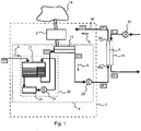
- FIG. 1 shows an exemplary embodiment of a dialysis device 2, which has an inflow 4 in order to direct a dialysis liquid in a flow direction 6 to a dialysis membrane 8.
- the dialysis device 2 also has an outlet 10 in order to drain a dialysate from the dialysis membrane 8 .
- a heat pump 12 is coupled to the inflow 4 and is designed to exchange heat energy between a heat reservoir 14 and the dialysis liquid in the inflow 4 .
- Outflow 10 is to be understood here as all devices or lines in which the dialysate after the dialysis process within the dialysis device 2 itself in the in figure 1 shown direction of flow 6 can be performed or transported.
- the inflow 4 of the dialysis machine 2 is to be understood as meaning any device or line within the dialysis machine 2 that is or can be used to conduct dialysis fluid or components of a dialysis fluid to the dialysis membrane 8 .
- the inflow 4 should also be understood in particular as a line system or one or more devices that carry or process dialysis fluid.
- the dialysis membrane 8 or a dialyzer 16 containing the dialysis membrane 8 is not part of the dialysis device 2 itself no cross-infection can occur with other patients.
- the dialyzer 16 has connections 18a and 18b in order to couple the inflow 4 and the outflow 10 of the dialysis machine 2 to the dialyzer 16, so that the dialysis liquid flows on one side (in 1 left) of the dialysis membrane 8 is passed through the dialyzer housing 16.
- Another blood circulation circuit which can include a blood pump 30, particularly in the case of veno-venous access in the patient, as is shown in 1 is shown.
- the heat pump 12 is, as in figure 1 shown coupled to the inflow or inlet 4 in such a way that heat energy can be exchanged between a heat reservoir 14 and the dialysis liquid in the inflow 4 by means of the heat pump 12 .
- the additional medium required for such an exchange of heat energy by means of a heat pump 12, which forms the heat reservoir, is in figure 1 shown only schematically.
- the heat pump 12 is coupled to the dialysis fluid in the inflow 4 by means of a heat exchanger 13 4 or the dialysis liquid or another liquid in the inflow 4 to be exchanged. This can be the case, for example, by means of radiation.
- the in figure 1 Dialysis device 2 shown a degassing device 20, which consists of a liquid reservoir 21, a degassing device 22 and a circulation pump 24.
- the inside figure 1 Circuit shown schematically within the degassing device 20 is used to degas the dialysis liquid, for which purpose it is first passed from a first partial reservoir within the liquid reservoir 21 via the degassing device 22 into a second partial reservoir.
- a feed pump 24 is provided which drives this partial circuit for the degassing.
- the degassed dialysis fluid is transported past the point at which the heat pump 12 is coupled to the inflow 4 .
- the heat pump 12 serves to heat the dialysate in the inflow 4 during dialysis, so that when it reaches the dialysis membrane 8 it is at least approximately at body temperature.
- the figure 1 The exemplary embodiment illustrated also has a further optional feed pump 28 which transports the dialysis liquid in the direction of the dialysis membrane 8 after it has been heated by means of the heat pump 12 .
- the delivered liquid or dialysis liquid can be delivered at a temperature of about 10°C.
- the temperature Before it flows through the external dialyzer 16, in the figure 1 illustrated embodiment increases the temperature to about 37 ° C. This is done by means of the heat pump 12, which takes the thermal energy required for this purpose from the heat reservoir 14.
- the degassing device 20 can also be arranged in the direction of flow 6 between a coupling point of the heat pump 12 and the dialysis membrane 8 or between the heat pump 12 and the feed pump 28 .
- the temperatures given are only to be understood as examples; any other temperatures are possible.
- the temperature of the water fed in or of the dialysis liquid at the beginning of the inflow 4 can also be significantly higher than 10° C., so that the ambient air can be used as the heat reservoir 14, for example.
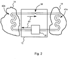
- the heat pump 12 is a machine that pumps heat from a heat source or a heat reservoir 14 to a medium 34 to be heated while supplying technical work.
- the heat pump was developed to pump thermal energy from a lower to a higher temperature level, so that the thermal energy contained in the medium at a lower temperature can be used to additionally heat a medium at a higher temperature, which would not be possible using normal heat exchangers.
- the heat pump 12 shown has a compressor or condenser 36 and an evaporator or an expansion valve 38 .
- a working medium often also referred to as refrigerant, circulates in a circulation direction 40 within a circuit driven by the compressor 36 .
- the compressor 36 can, for example, be driven electrically or by an internal combustion engine and causes the working medium to circulate within the circuit.
- the compressor 36 compresses the working medium or the refrigerant to a higher pressure, with the working medium, which is usually gaseous in front of the compressor 36, being heated and then liquefied. The energy released when the refrigerant is liquefied is transferred to the medium 34 to be heated in a heat exchanger 42b.
- a heat exchanger for example, can be used as the heat exchanger 42b.
- the heat can also be transferred to the medium to be heated by other mechanisms, for example by radiation.
- the heat pump 12 or the working medium in the exemplary embodiments of the invention is coupled to the medium 34 to be heated in such a way that an exchange of thermal energy is possible.
- the working medium or the refrigerant is expanded at a decompressor or at an expansion valve 38, where it cools down.
- the cold refrigerant is then fed to an evaporator 42a (water heat exchanger, geothermal probes, air evaporator) and changes to the gaseous state by absorbing ambient heat (anergy) from the heat source or from the heat reservoir 14 .
- evaporator 42a water heat exchanger, geothermal probes, air evaporator
- ambient heat ambient heat
- the ratio of usable heat output to the electrical power supplied is referred to as the performance number or in technical literature as the COP ("Coefficient of Performance") of the heat pump.
- the coefficient of performance has a theoretical maximum value that depends on the temperatures of the heat reservoir 14 and the medium 34 to be heated and can be derived from the Carnot process (named after Nicolas Leonard Sadi Carnot).
- the COP has a value of 8 or more. Values that can currently be achieved in practice are between 4 and 6. This means that 4 to 6 times the energy required to drive the heat pump 12 is transferred to the medium 34 to be heated Figures 3 and 4 , where, contrary to the usual mode of operation of the heat pump 12, thermal energy is transferred from a reservoir of higher temperature to a medium of lower temperature, the values achieved in practice are even higher because of this fact.
- This energy requirement can be significantly reduced when using a heat pump. Assuming that the entire energy used for the initial heating of the dialysis fluid in the inflow 4 would be removed from the dialysate in the outflow 10 by means of a Heat pump transferred to the dialysis fluid in the inflow 4, so that the dialysate in the outflow 10 would have approximately the same temperature as the dialysis fluid in the inflow 4 before heating, even with a minimum expected COP of 4, there is already an energy saving of 50%, since only a quarter of the thermal energy transferred must be used as energy to drive the heat pump. In the idealized example, the energy requirement can be reduced to less than 0.9 kWh. Taking into account the additional losses that actually occur in conventional dialysis machines, the increase in efficiency that can be achieved can be considerably higher.
- figure 3 shows another embodiment of a dialysis machine 2
- some components with the embodiment that is based on figure 1 was shown has in common. Therefore, in the following, only the differences to the in figure 1 embodiment shown in more detail.
- functionally similar or identical components are provided with the same reference symbols in the exemplary embodiments described herein.
- the components described with reference to the various exemplary embodiments and their functionality can also be arbitrarily exchanged within the individual exemplary embodiments.
- the heat pump 12 uses the dialysate in the outflow 10 as a heat reservoir.
- the heat pump 12 is coupled to the dialysate in the outflow 10, for example by means of a heat exchanger 44, in order to be able to use the outflowing dialysate as a heat reservoir.
- the compressor or compressor 36 contained in the heat pump 12 circulates the working medium of the heat pump 12 in the in figure 3 indicated direction to transfer thermal energy from the dialysate in the outflow 10 to the dialysis fluid in the inflow 4.
- the heat pump 12 can also transfer thermal energy from the dialysis liquid or a liquid in the inflow 4 in a second operating mode in which the working medium circulates in the other direction transferred to the dialysate or the liquid in the drain 10.
- This second mode of operation can be of great advantage during or after the cleaning of a dialysis machine.
- the dialysis device should reach a temperature of ⁇ 40 °C as quickly as possible so that the next treatment can begin.
- Hot disinfection is carried out with >85°C hot water to which disinfectant has been added. If a heat exchanger were used for energy recovery, the incoming fresh water would be undesirably heated by the heat exchanger when rinsing out the dialysis machine after disinfection, which would lengthen the rinsing phase. This reduction in efficiency is avoided when using a heat pump.
- a liquid in the inflow 4 can even be actively cooled, which leads to a further increase in efficiency.
- the use of a heat pump during the dialysis operation also has the advantage that the temperature of the dialysate emerging from the outflow 10 is lower than is conventionally the case. This is of great advantage in clinics, since it promotes bacterial growth in the drain or drain less than is the case when the dialysate draining has a temperature of 20° or more.
- FIG. 1 shows a further exemplary embodiment of a dialysis device, in which an additional heating device 50 is additionally coupled to the inflow 4 in order to heat the dialysis liquid in the inflow 4.
- the additional heating device 50 is arranged in the direction of flow 6 between the heat pump 12 and the dialysis membrane 8 in order to heat the dialysis liquid in the inflow 4 additionally and independently of the heat pump 12 .
- This can be used when starting up the dialysis machine to reduce the time required to heat the dialysis liquid to the required temperature if the dialysate in the outflow 10 does not yet have the temperature achieved in stationary operation at the beginning.
- an electric heater or a fast-regulating heater as the additional heating device 50, it can be ensured that the temperature of the dialysis fluid is within a required temperature window at all times.
- the additional heating device 50 can be coupled to the inflow 4 at any other point in order to heat the dialysis liquid in the inflow 4 .
- the additional heating device 50 can also be arranged between the feed pump 28 and the dialysis membrane 8 .
- the additional heating device 50 can also be arranged outside the circuit of the degassing device 20 .
- FIG 4 shows figure 4 an embodiment in which a heat pump 12 is used to provide the main heating capacity of the dialysis machine.
- a small heater is provided to achieve precise temperature control.
- the amount of incoming water or dialysis fluid and outgoing dialysate is largely the same. This means that if it is possible to make the heat from the waste water available to the inflow or inflow 4 via the heat pump 12, then only that which occurs as losses through convection or radiation must be supplied as differential energy.
- the heat pump 12 extracts in the evaporator on the outflow side, the energy as far as possible for the outflowing and used dialysate.
- the heat pump 12 compresses the coolant.
- the heat pump 12 On the other side of the heat circuit of the heat pump 12 sits a condenser in the water inlet or inflow. There, the energy is given off by the liquefaction to the inflowing water or the inflowing dialysis liquid. The heat pump 12 thus heats the incoming dialysis liquid with the energy extracted from the outlet. The temperature of the outflowing dialysate can even be below that of the inflowing water.
- the heater or additional heating device 50 can accelerate the heating-up phase at the beginning of the treatment when the water or the dialysate in the outflow or outflow 10 is not yet at operating temperature.
- the heater can also serve to increase the temperature control accuracy.
- a mixing valve or similar could also be used for temperature control.
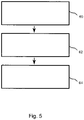
- figure 5 shows an example of a method for efficient operation of a dialysis machine.
- a dialysis fluid is supplied to a dialysis membrane 8 via an inflow 4 .
- a dialysate is drained from the dialysis membrane 8 via an outlet 10.
- the temperature control 64 the dialysis liquid fed to the dialysis membrane is temperature controlled with a heat pump 12 .
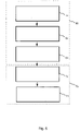
- figure 6 shows another example of a method for the efficient operation of a dialysis machine, which in a first operating mode 66 includes the steps in figure 5 comprises the method shown, wherein the dialysis membrane 8 supplied dialysis fluid is heated with the heat pump 12.
- the inflow 4 and the outflow 10 are cleaned during a cleaning 72 with a cleaning liquid flowing through the inflow 4 and the outflow 10 .
- a rinsing liquid or the dialysis liquid in the inflow 4 is cooled by means of the heat pump 12 operating in a second operating mode.
Description
Die vorliegende Erfindung befasst sich mit einer Dialysevorrichtung gemäß dem Oberbegriff des Patentanspruchs 1.The present invention relates to a dialysis machine according to the preamble of
Die Dialyse ist ein Blutreinigungsverfahren, das bei Nierenversagen als Ersatzverfahren zum Einsatz kommt. Die Dialyse ist neben der Nierentransplantation die wichtigste Nierenersatztherapie bei chronischem Nierenversagen und eine der möglichen Behandlungsalternativen bei akutem Nierenversagen. Ziel der Dialyse ist es, die Konzentration harnpflichtiger bzw. pathogener Substanzen im Blut bzw. im Körper des Patienten unterhalb einer toxischen Grenze zu halten.Dialysis is a blood purification procedure that is used as a replacement procedure in the case of kidney failure. In addition to kidney transplantation, dialysis is the most important renal replacement therapy for chronic kidney failure and one of the possible treatment alternatives for acute kidney failure. The aim of dialysis is to keep the concentration of urinary or pathogenic substances in the blood or in the patient's body below a toxic limit.
Blutreinigende Therapieverfahren basieren auf den physikalischen Grundprinzipien Diffusion, Osmose und Konvektion und teilweise auch auf Adsorption. Die unterschiedlichen Verfahren der Dialyse basieren dabei meist auf einem Stoffaustausch über spezielle, semipermeable Membranen, die im Folgenden als Dialysemembranen bezeichnet werden. Die Dialyse be- wirkt unter anderem die Reinigung des Blutes, den Entzug von Wasser aus dem Blutkreislauf und das Hinzufügen von Elektrolyten zum Blut. Bei der Dialyse befindet sich auf der einen Seite der Dialysemembran Blut oder Blutplasma und auf der anderen Seite der Membran eine Dialyselösung bzw. eine Dialysierflüssigkeit. Je nach Beschaffenheit der Membran diffundieren unterschiedliche Substanzen durch die Membran vom Blut in die Dialysierflüssigkeit und werden so dem Blutkreislauf entzogen. Gleichzeitig können andere Substanzen, beispielsweise Elektrolyte, auch von der Dialysierflüssigkeit in das Blut diffundieren. Eine der entscheidenden Parameter ist dabei die Beschaffenheit der Membran und insbesondere deren Porengröße, durch die wesentlich bestimmt wird, welche Substanzen bei der Dialyse aus dem Blut entfernt werden. Bei Verwendung solcher semipermeabler (teildurchlässiger) Membranen spricht man daher auch von selektiver Diffusion. Während die Membran im Wesentlichen die Art bzw. die Größe der prinzipiell austauschbaren Substanzen bestimmt, wird die Diffusionsgeschwindigkeit und damit der tatsächliche Austausch im Wesentlichen durch die Konzentrationsunterschiede der jeweiligen Substanzen auf den unterschiedlichen Seiten der Membran bestimmt. Die zu entfernenden Substanzen werden grob in niedrig-, mittel-, und hochmolekulare Substanzen klassifiziert. Durch Osmose bzw. eine künstlich zwischen den unterschiedlichen Seiten der Dialysemembran erzeugte Druckdifferenz kann darüber hinaus der Flüssigkeitshaushalt des Patienten kontrolliert werden, indem dem zu reinigenden Blut Flüssigkeit entzogen wird. Zusätzlich können durch spezielle Zusätze in der Dialysierflüssigkeit der Säure-Basenstatus und die Elektrolytzusammensetzung des Blutes beeinflusst und reguliert werden.Blood-cleansing therapy methods are based on the basic physical principles of diffusion, osmosis and convection, and in some cases also on adsorption. The different methods of dialysis are mostly based on an exchange of substances via special, semi-permeable membranes, which are referred to below as dialysis membranes. Among other things, dialysis cleans the blood, removes water from the bloodstream and adds electrolytes to the blood. During dialysis, there is blood or blood plasma on one side of the dialysis membrane and a dialysis solution or dialysis fluid on the other side of the membrane. Depending on the composition of the membrane, different substances diffuse through the membrane from the blood into the dialysis fluid and are thus withdrawn from the bloodstream. At the same time, other substances, for example electrolytes, can also diffuse from the dialysis fluid into the blood. One of the decisive parameters is the nature of the membrane and in particular its pore size, which essentially determines which substances are removed from the blood during dialysis. When using such semi-permeable (partially permeable) membranes, one therefore also speaks of selective diffusion. While the membrane essentially determines the type and size of the substances that can in principle be exchanged, the diffusion speed and thus the actual exchange is essentially determined by the concentration differences of the respective substances on the different sides of the membrane. The substances to be removed are roughly classified into low, medium and high molecular substances. In addition, the fluid balance of the patient can be controlled by osmosis or a pressure difference artificially generated between the different sides of the dialysis membrane, in that fluid is withdrawn from the blood to be cleaned. In addition, the acid-base status and the electrolyte composition of the blood can be influenced and regulated by special additives in the dialysis fluid.
Als Dialysemembranen werden zum einen künstliche bzw. technische Membranen verwendet, zum anderen aber auch körpereigene, physiologische Membranen. Es wird also bei der Dialyse zwischen extrakorporalen Verfahren, die künstliche Membranen außerhalb des Körpers verwenden und intrakorporalen Verfahren, die innerhalb des Körpers durchgeführt werden und dabei körpereigene Membranen nutzen, unterschieden.On the one hand artificial or technical membranes are used as dialysis membranes, on the other hand endogenous, physiological membranes. In dialysis, a distinction is made between extracorporeal methods that use artificial membranes outside the body and intracorporeal methods that are carried out inside the body and use the body's own membranes.
Ein Beispiel für ein intrakorporales Dialyseverfahren ist die Peritonealdialyse, bei der zur Blutreinigung das Peritoneum (Bauchfell) als Membran genutzt wird. Hier wird die Dialysierflüssigkeit durch einen Katheterzugang in die Bauchhöhle des Patienten direkt eingebracht und als Dialysat nach erfolgter Equilibrierung der Stoffkonzentrationen ausgetauscht. Typisch werden so über einen Tag verteilt drei bis sechs Wechsel der Dialyseflüssigkeit mit einem Volumen von jeweils etwa 2,5 bis 4 Litern durchgeführt. Zur Vermeidung von negativen Gesundheitsfolgen für den Patienten muss die Dialysierflüssigkeit vor dem Einbringen in die Bauchhöhle jeweils auf Körpertemperatur gebracht werden.An example of an intracorporeal dialysis method is peritoneal dialysis, in which the peritoneum (peritoneum) is used as a membrane to clean the blood. Here, the dialysis liquid is introduced directly into the patient's abdominal cavity through a catheter access and exchanged as dialysate after the substance concentrations have been equilibrated. Typically, three to six changes of the dialysis liquid, each with a volume of about 2.5 to 4 liters, are carried out over the course of a day. To avoid negative health consequences for the patient, the dialysis fluid must be brought to body temperature before it is introduced into the abdominal cavity.
Ein Beispiel für ein extrakorporales Dialyseverfahren ist die weltweit am meisten angewandte Hämodialyse. Hier wird nach dem Prinzip des Konzentrationsausgleichs kleinmolekularer Substanzen zweier Flüssigkeiten verfahren, die außerhalb des Körpers in einem Dialysator durch eine künstliche semipermeable Dialysemembran getrennt sind. Durch die Dialysemembran getrennt befindet sich auf der einen Seite das Blut mit Nephrotoxinen, Elektrolyten, wie z. B. Kalium und Phosphat, sowie harnpflichtigen Substanzen. Auf der anderen Seite der Dialysemembran befindet sich als Dialysierflüssigkeit eine keimarme, aufbereitete Lösung, die keine Abfallprodukte enthält und einen an den jeweiligen Bedürfnissen des Patienten orientierten Anteil an Elektrolyten aufweist. Die semipermeable Dialysemembran zwischen Blut und Dialyselösung bzw. Dialysierflüssigkeit besitzt Poren, die kleine Moleküle wie Wasser, Elektrolyte und harnpflichtige Substanzen (z. B. Harnstoff, Harnsäure) durchlassen, aber große Moleküle wie Eiweiße und Blutzellen zurückhalten. Typisch sind bei dem Verfahren der Hämodialyse drei bis vier Behandlungen ä etwa 4 h pro Woche. Je Behandlung wird eine erhebliche Menge Dialysierflüssigkeit benötigt, das permanent auf der dem Blut abgewandten Seite der Dialysemembran an der Membran vorbeifließt. Häufig wird dabei die Dialysierflüssigkeit im Gegenstrom zum Blut geführt. Die Dialysierflüssigkeit wird nach einmaliger Verwendung, wenn es mit den harnpflichtigen Substanzen angereichert ist, als Dialysat entsorgt. Allgemein wird aus Gründen einer eindeutigen Zuordnung die zur Dialyse verwendete Flüssigkeit vor der Anreicherung mit harnpflichtigen Stoffen als Dialysierflüssigkeit bezeichnet, während die mit den harnpflichtigen Stoffen angereicherte Flüssigkeit als Dialysat bezeichnet wird. Dabei kann die Menge verbrauchter Dialysierflüssigkeit pro Anwendung 100 1 und mehr betragen. Allein die große Menge herzustellender und verbrauchter Dialysierflüssigkeit macht eine Dialysebehandlung äußerst kostspielig. Zusätzlich zum hohen Ressourcenverbrauch erhöht die zur Aufbereitung der Dialysierflüssigkeit verbrauchte Energie die Kosten erheblich.An example of an extracorporeal dialysis method is the hemodialysis most commonly used worldwide. The procedure here is based on the principle of equalizing the concentration of small-molecular substances in two liquids, which are separated outside the body in a dialyzer by an artificial semi-permeable dialysis membrane. Separated by the dialysis membrane is the blood with nephrotoxins, electrolytes such as e.g. B. potassium and phosphate, as well as urinary substances. On the other side of the dialysis membrane is a germ-poor, processed solution as dialysis fluid, which contains no waste products and has a proportion of electrolytes based on the respective needs of the patient. The semi-permeable dialysis membrane between the blood and the dialysis solution or dialysis liquid has pores that allow small molecules such as water, electrolytes and urinary substances (e.g. urea, uric acid) to pass through, but large molecules such as proteins and blood cells are retained. In the hemodialysis process, three to four treatments of around 4 hours per week are typical. A considerable amount of dialysis fluid is required for each treatment, which constantly flows past the dialysis membrane on the side of the dialysis membrane facing away from the blood. The dialysis fluid is often fed in countercurrent to the blood. After it has been used once, the dialysis fluid is disposed of as dialysate if it has been enriched with the substances excreted in the urine. In general, for reasons of clear assignment, the liquid used for dialysis before being enriched with substances excreted in the urine is referred to as dialysis liquid, while the liquid enriched with substances excreted in the urine is referred to as dialysate. The amount of dialysis fluid used per application can be 100 liters or more. The large amount of dialysis fluid to be produced and used alone is enough dialysis treatment is extremely expensive. In addition to the high consumption of resources, the energy used to prepare the dialysis fluid increases the costs significantly.
Neben der Menge der zugeführten bzw. entnommenen Flüssigkeit aus dem Blut muss auch die Temperatur des Blutes genau kontrolliert werden, um eine schwerwiegende Schädigung des Patienten zu verhindern. Das dem Patienten nach dessen Reinigung wieder zugeführte Blut muss eine von der Körpertemperatur des Patienten abhängige Temperatur aufweisen, um solche Gesundheitsschäden zu vermeiden. Dies wird dadurch erreicht, dass die Dialysierflüssigkeit, und damit auch die Dialysemembran und die diese Membran umgebenden Komponenten auf Körpertemperatur aufgeheizt werden, um ein Abkühlen des Blutes in dem extrakorporalen Kreislauf zu verhindern.In addition to the amount of liquid supplied or removed from the blood, the temperature of the blood must also be precisely controlled in order to prevent serious damage to the patient. The blood returned to the patient after the patient has been cleaned must have a temperature that is dependent on the patient's body temperature in order to avoid such damage to health. This is achieved in that the dialysis fluid, and thus also the dialysis membrane and the components surrounding this membrane, are heated to body temperature in order to prevent the blood in the extracorporeal circuit from cooling down.
Bevor die Dialysierflüssigkeit mittels eines Dialyseapparats in einem die Filtermembran aufweisenden Dialysator am Blut des Patienten vorbeigeführt wird, wird es also von der Eintrittstemperatur (typ. 10°C) auf eine höhere Temperatur in ungefährer Höhe der Bluttemperatur (typ. 36°C) aufgeheizt. Nachdem das Dialysat durch den Dialysierfilter geströmt ist, ist es gebraucht und gelangt in den Abfluss. Dieses Temperieren der großen Menge von Dialysierflüssigkeit verbraucht eine erhebliche Menge zusätzlicher Energie.Before the dialysis fluid is conducted past the patient's blood by means of a dialysis machine in a dialyzer having the filter membrane, it is heated from the inlet temperature (typically 10°C) to a higher temperature approximately equal to the blood temperature (typically 36°C). After the dialysate has passed through the dialysis filter, it is used and goes down the drain. This tempering of the large amount of dialysis fluid consumes a significant amount of additional energy.
Bei den extrakorporalen Verfahren wie der Hämodialyse (HD) sollte zudem nach jeder Dialysebehandlung der verwendete Apparat, also die Dialysevorrichtung, sterilisiert werden, um eine Kreuz-Infektion zwischen einzelnen Patienten zu verhindern. Zu diesem Zweck wird häufig die so genannte Heißdesinfektion angewendet. Bei dieser wird ein Wasser/ Desinfektionsmittel-Gemisch im Dialysat-Kreislauf der Dialysevorrichtung auf >85°C aufgeheizt und für eine bestimmte Zeit, typisch etwa 15 Minuten, zirkuliert. Nach Ablauf der Zeit sollte das Desinfektionsmittel möglichst schnell ausgespült und die Maschine bzw. die Dialysevorrichtung möglichst schnell wieder auf ca. 35° abgekühlt werden, um die nächste Therapie zu ermöglichen.In the case of extracorporeal procedures such as hemodialysis (HD), the apparatus used, i.e. the dialysis device, should also be sterilized after each dialysis treatment in order to prevent cross-infection between individual patients. So-called hot disinfection is often used for this purpose. In this case, a water/disinfectant mixture is heated to >85°C in the dialysate circuit of the dialysis machine and circulated for a specific time, typically around 15 minutes. After the time has elapsed, the disinfectant should be rinsed out as quickly as possible and the machine or the dialysis machine should be cooled down again to around 35°C as quickly as possible in order to enable the next therapy.
Als weitere extrakorporale Dialyseverfahren seien hier nur beispielhaft die Hämofiltration oder die Hämodiafiltration genannt, die zum Teil noch höhere Mengen an Ressourcen und Energie verbrauchen und daher bei ihrer Anwendung ähnliche oder höhere Kosten verursachen.As further extracorporeal dialysis methods, hemofiltration or hemodiafiltration are only mentioned here as examples, some of which consume even higher amounts of resources and energy and therefore cause similar or higher costs when used.
Beispielsweise zeigt das
Aufgrund des hohen Ressourcenverbrauchs und des hohen Energieverbrauchs bei einer Dialysebehandlung besteht eine erhebliche Notwendigkeit, Dialysevorrichtungen bzw. Verfahren zum Betreiben von Dialysevorrichtungen effizienter zu gestalten.Due to the high consumption of resources and the high energy consumption in a dialysis treatment, there is a considerable need to make dialysis devices and methods for operating dialysis devices more efficient.
Die Aufgabe wird prinzipiell durch eine Dialysevorrichtung mit den Merkmalen des Patentanspruchs 1 gelöst.In principle, the object is achieved by a dialysis device having the features of
Ein Aspekt der vorliegenden Erfindung ist demnach in der Verwendung einer Wärmepumpe zu sehen, um in der erfindungsgemäßen Dialysevorrichtung eine Dialysierflüssigkeit im Zufluss zu einer Dialysemembran zu temperieren. Dies erfolgt vorzugsweise nach dem folgenden Steuerungsprozess:
- Zuleiten der Dialysierflüssigkeit zu der Dialysemembran über den Zufluss,
- Ableiten der verbrauchten Dialysierflüssigkeit von der Dialysemembran über einen Abfluss und
- Temperieren der der Dialysemembran zugeleiteten Dialysierflüssigkeit mit der Wärmepumpe.
- Supplying the dialysis liquid to the dialysis membrane via the inflow,
- Deriving the used dialysis fluid from the dialysis membrane via a drain and
- Tempering the dialysis fluid fed to the dialysis membrane with the heat pump.
Bei einigen Ausführungsbeispielen von Dialysevorrichtungen wird die Wärmepumpe folglich mit einem Zufluss, der dazu dient, eine Dialysierflüssigkeit zu einer Dialysemembran zu leiten, gekoppelt, um Wärmeenergie zwischen einem Wärmereservoir und der Dialysierflüssigkeit im Zufluss auszutauschen. Dies kann zu einer erheblichen Reduktion des Energieverbrauchs bzw. einer erheblichen Erhöhung der Effizienz bei der Temperierung der Dialysierflüssigkeit und somit zu einer Erhöhung der Effizienz der Dialysevorrichtung führen.In some exemplary embodiments of dialysis devices, the heat pump is consequently coupled to an inflow, which serves to direct a dialysis liquid to a dialysis membrane, in order to exchange heat energy between a heat reservoir and the dialysis liquid in the inflow. This can lead to a significant reduction in energy consumption or a significant increase in efficiency when controlling the temperature of the dialysis liquid and thus to an increase in the efficiency of the dialysis device.
Bei einigen Ausführungsbeispielen wird die Wärmepumpe genutzt, um die Dialysierflüssigkeit im Zufluss zu erwärmen. Durch Verwendung einer Wärmepumpe, die verglichen mit anderen Heizmöglichkeiten, wie beispielsweise einer elektrischen Direktheizung, einen erheblich höheren Wirkungsgrad aufweist, kann die Energie, die zum Betrieb einer Dialysevorrichtung erforderlich ist, erheblich reduziert werden. Der höhere Wirkungsgrad bei der Verwendung einer Wärmepumpe rührt daher, dass die von der Wärmepumpe an die Dialysierflüssigkeit abgegebene Wärmeenergie größer ist als die zum Betrieb der Wärmepumpe erforderliche Energie, da die Wärmepumpe die Wärmeenergie vom Wärmereservoir an die Dialysierflüssigkeit transferiert anstatt sie selbst zu erzeugen. Somit ist die Wärmepumpe sowohl anderen Heizungen, die Primärenergieträger direkt in Wärmeenergie umwandeln als auch herkömmlichen Stromheizungen überlegen.In some embodiments, the heat pump is used to heat the dialysis fluid in the inflow. By using a heat pump, which has a significantly higher efficiency compared to other heating options, such as direct electrical heating, the energy required to operate a dialysis machine can be significantly reduced. The higher degree of efficiency when using a heat pump is due to the fact that the heat energy transferred from the heat pump to the dialysis fluid is greater than the energy required to operate the heat pump, since the heat pump transfers the heat energy from the heat reservoir to the dialysis fluid instead of generating it itself. The heat pump is therefore superior to both other heating systems that convert primary energy sources directly into thermal energy and conventional electric heating systems.
Bei einigen weiteren Ausführungsbeispielen wird ein Umgebungsmedium, wie z. B. die Umgebungsluft, als Wärmereservoir benutzt. Der erzielbare Effizienzgewinn bei der Verwendung 10 einer Wärmepumpe, der sich aus dem Carnot-Prozess ableitet, hängt von der Temperaturdifferenz zwischen den beiden mit der Wärmepumpe gekoppelten Medien ab, vorliegend also von der Temperatur des Wärmereservoirs und der Temperatur der Dialysierflüssigkeit. Dieser auch als Leistungszahl (Coefficient of Performance, COP) bezeichnete Faktor wird umso größer, je höher die Temperatur des Wärmereservoirs relativ zur Temperatur der Dialysierflüssigkeit ist. So kann beispielsweise in südlichen Ländern eine Wärmepumpe im Zufluss einer Dialysevorrichtung auf besonders effiziente Art und Weise die Dialysierflüssigkeit erwärmen, wenn als Wärmereservoir die Umgebungsluft genutzt wird. Gleichzeitig wird bei der Verwendung einer solchen Wärmepumpe die Umgebungsluft gekühlt, so dass diese neben der erforderlichen Funktionalität für die Dialysevorrichtung auch ein angenehmes Klima für den Patienten bewirken kann.In some further embodiments, a surrounding medium, such as e.g. B. the ambient air used as a heat reservoir. The gain in efficiency that can be achieved when using a heat pump, which is derived from the Carnot cycle, depends on the temperature difference between the two media coupled to the heat pump, in this case on the temperature of the heat reservoir and the temperature of the dialysis liquid. This also as a performance number (Coefficient of Performance, COP) designated factor is greater, the higher the temperature of the heat reservoir is relative to the temperature of the dialysis fluid. In southern countries, for example, a heat pump in the inflow of a dialysis machine can heat the dialysis fluid in a particularly efficient manner if the ambient air is used as a heat reservoir. At the same time, when using such a heat pump, the ambient air is cooled so that, in addition to providing the necessary functionality for the dialysis machine, it can also produce a pleasant climate for the patient.
Bei weiteren Ausführungsbeispielen ist die Wärmepumpe zusätzlich mit einem Abfluss der Dialysevorrichtung gekoppelt, der verwendet wird, um das bereits verwendete Dialysat von der Dialysemembran abzuleiten. Hierbei kann das Dialysat im Abfluss als Wärmereservoir verwendet werden.In further embodiments, the heat pump is additionally coupled to an outflow of the dialysis machine, which is used to drain the already used dialysate from the dialysis membrane. Here, the dialysate in the drain can be used as a heat reservoir.
Bei diesen Ausführungsbeispielen kann in einem ersten Betriebsmodus das vorgeheizte und sich dadurch annähernd auf der Körpertemperatur befindliche, bereits benutzte Dialysat verwendet werden, um als Wärmereservoir bzw. als Wärmequelle für die Wärmepumpe zu dienen. Das heißt, die Energie, die bereits aufgewendet wurde, um das verbrauchte Dialysat zu erwärmen, kann zu großen Teilen wiedergewonnen werden, um die frische Dialysierflüssigkeit im Zufluss aufzuheizen. Dies führt zu einer weiteren erheblichen Reduktion des Energieverbrauchs bei der Dialyse, also insgesamt zu einer Erhöhung der Effizienz beim Betrieb einer Dialysevorrichtung. Dabei ist die Effizienz der Wiedergewinnung von Wärme mittels einer Wärmepumpe aus den oben genannten Gründen erheblich größer als beispielsweise die Effizienz eines herkömmlichen Wärmetauschers.In these exemplary embodiments, in a first operating mode, the dialysate that has already been used and has been preheated and is therefore approximately at body temperature can be used to serve as a heat reservoir or as a heat source for the heat pump. This means that the energy that has already been used to heat the used dialysate can be largely recovered to heat the fresh dialysis fluid in the inflow. This leads to a further significant reduction in energy consumption during dialysis, ie an overall increase in efficiency when operating a dialysis device. The efficiency of heat recovery using a heat pump is considerably greater than, for example, the efficiency of a conventional heat exchanger for the reasons mentioned above.
Wenngleich bei einigen Ausführungsbeispielen das Wärmereservoir eine höhere Temperatur aufweist als die Dialysierflüssigkeit, soll der Begriff Wärmereservoir hier und im Folgenden nicht als in irgendeiner Art von einer Temperatur abhängig verstanden werden. Als Wärmereservoir wird jedwedes Energiereservoir oder Medium verstanden, dem Wärmeenergie entnommen oder zugeführt werden kann.Although in some exemplary embodiments the heat reservoir has a higher temperature than the dialysis liquid, the term heat reservoir should not be understood here and in the following as being dependent on a temperature in any way. A heat reservoir is any energy reservoir or medium from which thermal energy can be removed or supplied.
In einem zweiten Betriebsmodus erlauben es weitere Ausführungsbeispiele von Dialysevorrichtungen, Wärmeenergie von einer Flüssigkeit im Zufluss an das Wärmereservoir zu übertragen, um die Dialysierflüssigkeit oder eine Spülflüssigkeit im Zufluss abzukühlen. In diesem Betriebsmodus kann also beispielsweise das Dialysat oder eine andere Flüssigkeit im Abfluss als Wärmesenke verwendet werden. Dies kann eine Zeit, die eine Dialysevorrichtung nach der Heißdesinfektion benötigt, um auf eine der Körpertemperatur vergleichbare Betriebstemperatur abzukühlen, erheblich verringern, da eine Spülflüssigkeit im Zulauf aktiv gekühlt wird. Dadurch wird sowohl die zur Spülung erforderliche Flüssigkeitsmenge als auch die Spülzeit verringert, was insgesamt zu einer Steigerung der Effizienz beim Betrieb einer Dialysevorrichtung führt.In a second operating mode, further exemplary embodiments of dialysis devices allow thermal energy to be transferred from a liquid in the inflow to the heat reservoir in order to cool the dialysis liquid or a rinsing liquid in the inflow. In this operating mode, for example, the dialysate or another liquid in the outflow can be used as a heat sink. This can significantly reduce the time that a dialysis device needs after the hot disinfection in order to cool down to an operating temperature that is comparable to the body temperature, since a rinsing liquid in the inlet is actively cooled. This reduces both the amount of liquid required for rinsing and the rinsing time, which overall leads to an increase in efficiency when operating a dialysis machine.
Bei einigen Ausführungsbeispielen ist in einer Flussrichtung der Dialysierflüssigkeit zwischen der Wärmepumpe und der Dialysemembran ergänzend eine Zusatzheizeinrichtung mit dem Zufluss gekoppelt, um die zufließende, noch unverbrauchte Dialysierflüssigkeit zu erwärmen. Dies kann zu einer Beschleunigung des Aufheizens der Dialysierflüssigkeit zu Beginn des Betriebes der Dialysevorrichtung beitragen, wenn das Dialysat im Abfluss noch nicht die gewünschte Betriebstemperatur erreicht hat. Eine solche Zusatzheizeinrichtung kann beispielsweise eine Stromheizung sein und deutlich kleiner dimensioniert werden, als bei Dialysevorrichtung, die allein über eine herkömmliche Heizeinrichtung verfügen, da die Zusatzheizeinrichtung hier nur unterstützend tätig ist.In some exemplary embodiments, an additional heating device is additionally coupled to the inflow in a flow direction of the dialysis fluid between the heat pump and the dialysis membrane, in order to heat the inflowing, still unused dialysis fluid. This can contribute to accelerating the heating of the dialysis fluid at the beginning of the operation of the dialysis machine when the dialysate in the outflow has not yet reached the desired operating temperature. Such an additional heating device can, for example, be an electric heater and be dimensioned significantly smaller than in the case of dialysis machines that only have a conventional heating device, since the additional heating device only has a supporting role here.
Bei einigen Ausführungsbeispielen wird die Zusatzheizeinrichtung dafür verwendet, eine Feinregulierung der Temperatur der Dialysierflüssigkeit im Zufluss vorzunehmen. Dies kann dazu verwendet werden, um sicherzustellen, dass sich die Temperatur der Dialysierflüssigkeit zu jedem Zeitpunkt innerhalb eines erforderlichen Temperaturfensters befindet. Bei einigen Ausführungsbeispielen kann die Zusatzheizeinrichtung auch dazu verwendet werden, um bei einer Reinigung der Dialysevorrichtung eine zur Reinigung verwendete Flüssigkeit auf eine höhere Temperatur aufzuheizen, als die Dialysierflüssigkeit während der Dialyse.In some exemplary embodiments, the additional heating device is used to fine-tune the temperature of the dialysis liquid in the inflow. This can be used to ensure that the dialysis fluid temperature is within a required temperature window at all times. In some exemplary embodiments, the additional heating device can also be used to heat a liquid used for cleaning to a higher temperature when cleaning the dialysis machine than the dialysis liquid during dialysis.
Einige Ausführungsbeispiele der vorliegenden Erfindung werden nachfolgend, bezugnehmend auf die beigefügten Figuren, näher erläutert. Es zeigen:
- Fig. 1
- ein Ausführungsbeispiel einer Dialysevorrichtung mit Wärmepumpe;
- Fig. 2
- eine Prinzipskizze einer Wärmepumpe;
- Fig. 3
- ein weiteres Ausführungsbeispiel einer Dialysevorrichtung, bei der als Wärmereservoir ein Dialysat im Abfluss verwendet wird;
- Fig. 4
- ein weiteres Ausführungsbeispiel einer Dialysevorrichtung mit einer Zusatzheizeinrichtung;
- Fig. 5
- ein Beispiel für ein Verfahren zum Betreiben einer Dialysevorrichtung; und
- Fig. 6
- ein weiteres Beispiel für ein Verfahren zum Betreiben einer Dialysevorrichtung.
- 1
- an embodiment of a dialysis machine with a heat pump;
- 2
- a schematic diagram of a heat pump;
- 3
- a further exemplary embodiment of a dialysis device in which a dialysate in the outflow is used as the heat reservoir;
- 4
- a further exemplary embodiment of a dialysis machine with an additional heating device;
- figure 5
- an example of a method for operating a dialysis machine; and
- 6
- another example of a method for operating a dialysis machine.
Als Abfluss 10 sind vorliegend alle Vorrichtungen bzw. Leitungen zu verstehen, in denen das Dialysat nach dem Vorgang der Dialyse innerhalb der Dialysevorrichtung 2 selbst in der in
Um das Blut des Patienten auf der anderen Seite (in
Die Wärmepumpe 12 ist, wie in
Als weitere optionale Komponenten zeigt die in
Die entgaste Dialysierflüssigkeit wird nach der Entgasungsvorrichtung 20, die in Flussrichtung 6 vor der Wärmepumpe 12 angeordnet ist, an derjenigen Stelle vorbeitransportiert, an der die Wärmepumpe 12 mit dem Zufluss 4 gekoppelt ist. Die Wärmepumpe 12 dient dazu, dass Dialysat im Zufluss 4 während der Dialyse zu erwärmen, so dass dieses, wenn es die Dialysemembran 8 erreicht, zumindest annähernd Körpertemperatur aufweist. Um den Kreislauf der Dialysierflüssigkeit und des Dialysats aufrechtzuerhalten, weist das in
In
Es versteht sich von selbst, dass hier, wie auch in den nachfolgend diskutierten Ausführungsbeispielen, die exakte Position der Kopplung der einzelnen Komponenten mit dem Zufluss 4 bzw. deren Position innerhalb des Zuflusses 4 beliebig miteinander ausgetauscht werden können. Beispielsweise kann die Entgasungsvorrichtung 20 in Flussrichtung 6 auch zwischen einer Koppelstelle der Wärmepumpe 12 und der Dialysemembran 8 bzw. zwischen der Wärmepumpe 12 und der Förderpumpe 28 angeordnet sein. Selbstverständlich sind auch die angegebenen Temperaturen nur als Beispiele zu verstehen, es sind beliebige andere Temperaturen möglich. Insbesondere in wärmeren Ländern oder zu wärmeren Jahreszeiten kann die Temperatur des eingespeisten Wassers bzw. der Dialysierflüssigkeit am Anfang des Zuflusses 4 auch deutlich höher liegen als 10°C, sodass als Wärmereservoir 14 beispielsweise die Umgebungsluft verwendet werden kann.It goes without saying that here, as well as in the exemplary embodiments discussed below, the exact position of the coupling of the individual components to the
Anhand von
Die Wärmepumpe 12 ist eine Maschine, die unter Zufuhr von technischer Arbeit Wärme von einer Wärmequelle bzw. einem Wärmereservoir 14 zu einem zu erwärmenden Medium 34 pumpt. Entwickelt wurde die Wärmepumpe, um Wärmeenergie von einem niedrigeren zu einem höheren Temperaturniveau zu pumpen, sodass die Wärmeenergie, die in dem niedriger temperierten Medium enthalten ist, zum zusätzlichen Heizen eines Mediums auf höherer Temperatur genutzt werden kann, was mittels normaler Wärmetauscher nicht möglich wäre.The
Bei einer Wärmepumpenheizung wird die auf einem hohen Temperaturniveau anfallende Verflüssigungswärme eines in dem Wärmepumpenkreislauf verwendeten Arbeitsmediums zum Heizen genutzt. Dagegen wird bei einer Kältemaschine die Abkühlung eines Kältemittels beim Entspannen und Verdampfen genutzt, um ein Fluid abzukühlen. Wärmepumpen und Kältemaschinen unterscheiden sich lediglich hinsichtlich der genutzten Energie, der entweder zum Abkühlen oder zum Aufwärmen genutzten Wärmeleistung. Der grundlegende Prozess, der in
Die in
Nach dem Übertragen der Wärmeenergie wird das Arbeitsmedium bzw. das Kältemittel an einem Dekomprimierer bzw. an einem Expansionsventil 38 entspannt, wobei es sich abkühlt. Das kalte Kältemittel wird dann einem Verdampfer 42a (Wasser-Wärmetauscher, Erdwärmesonden, Luftverdampfer) zugeführt und geht durch Aufnahme von Umgebungswärme (Anergie) aus der Wärmequelle bzw. aus dem Wärmereservoir 14 in den gasförmigen Zustand über. Bezüglich der Kopplung des Verdampfers mit dem Wärmereservoir 14 gilt das oben zu der Kopplung mit dem zu erwärmende Medium 34 gesagte.After the thermal energy has been transferred, the working medium or the refrigerant is expanded at a decompressor or at an
Das Verhältnis von nutzbarer Wärmeleistung zu zugeführter elektrischer Leistung wird als Leistungszahl bzw. in der Fachliteratur als COP ("Coefficient of Performance") der Wärmepumpe bezeichnet. Die Leistungszahl hat einen theoretischen Maximalwert, der von den Temperaturen des Wärmereservoirs 14 und des zu erwärmenden Mediums 34 abhängt und aus dem Carnot-Prozess (benannt nach Nicolas Leonard Sadi Carnot) abgeleitet werden kann.The ratio of usable heat output to the electrical power supplied is referred to as the performance number or in technical literature as the COP ("Coefficient of Performance") of the heat pump. The coefficient of performance has a theoretical maximum value that depends on the temperatures of the
Bei typischen Temperaturen hat der COP einen Wert von 8 oder darüber. In der Praxis derzeit erzielbare Werte liegen zwischen 4 und 6. Dies bedeutet, dass das 4- bis 6- fache derjenigen Energie, die zum Antrieb der Wärmepumpe 12 benötigt wird, an das zu erwärmende Medium 34übertragen wird.BeimEinsatz derWärmepumpe 12 in denDialysevorrichtungen der
Nimmt man beispielsweise an, die Dialysierflüssigkeit muss im Zufluss 4 von 10°C auf etwa 36°C erhitzt werden, und werden für eine Behandlung ca. 120 1 benötigt, führt dies zu einem Wärmeenergiebedarf von ca. 3,6 kWh, sofern man idealisierend annimmt, die Wärmeenergie könnte bei der Aufheizung verlustfrei aus einem anderen Energieträger erzeugt werden, was in der Realität natürlich nicht der Fall ist.If one assumes, for example, that the dialysis fluid in the
Selbst bei der Verwendung eines Wärmetauschers zwischen dem Dialysat im Abfluss 10 und der Dialysierflüssigkeit im Zufluss 4 kann nur ein kleiner Teil der eingesetzten Energie wiederverwendet werden. Wirkungsgrade für sehr gute Wärmetauscher liegen typischerweise bei weniger als 60% - 70%, wobei ein Wärmeenergieübertrag nur stattfinden kann, solange das Dialysat im Abfluss 10 noch wärmer ist als die Dialysierflüssigkeit im Zufluss 4. Dies ist bei Verwendung einer Wärmepumpe kein limitierender Faktor. Selbst wenn man einen sehr guten Wärmetauscher annähme, ergibt sich für eine herkömmliche Dialysevorrichtung immer noch ein Mindestenergiebedarf von ca. 1,80 kWh zur Heizung der Dialysierflüssigkeit für eine typische Behandlung.Even when using a heat exchanger between the dialysate in the
Dieser Energiebedarf kann bei Verwendung einer Wärmepumpe erheblich reduziert werden. Unter der Annahme, man würde die gesamte zur anfänglichen Erwärmung der Dialysierflüssigkeit im Zufluss 4 verwendete Energie von dem Dialysat im Abfluss 10 mittels einer Wärmepumpe an die Dialysierflüssigkeit im Zufluss 4 übertragen, sodass das Dialysat im Abfluss 10 in etwa dieselbe Temperatur hätte wie die Dialysierflüssigkeit im Zufluss 4 vor dem Erwärmen, ergibt sich selbst bei einem minimal zu erwartenden COP von 4 bereits eine Energieersparnis von 50%, da nur ein Viertel der übertragenen Wärmeenergie als Energie zum Antrieb der Wärmepumpe verwendet werden muss. Im idealisierten Beispiel kann also der Energiebedarf auf unter 0,9 kWh reduziert werden. Unter Berücksichtigung der tatsächlich auftretenden zusätzlichen Verluste in herkömmlichen Dialysevorrichtungen, kann die erzielbare Effizienzsteigerung erheblich höher sein.This energy requirement can be significantly reduced when using a heat pump. Assuming that the entire energy used for the initial heating of the dialysis fluid in the
Bei dem in
Dieser zweite Betriebsmodus kann während oder nach der Reinigung einer Dialysevorrichtung von großem Vorteil sein. Während der Ausspülphase am Ende der Heißdesinfektion soll die Dialysevorrichtung möglichst schnell wieder eine Temperatur <40 °C erreichen, um mit der nächsten Behandlung beginnen zu können. Die Heißdesinfektion wird mit >85°C heißem Wasser, dem Desinfektionsmittel zugesetzt ist, durchgeführt. Verwendete man zur Energierückgewinnung einen Wärmetauscher, würde beim Ausspülen der Dialysevorrichtung nach der Desinfektion das zulaufende Frischwasser unerwünscht durch den Wärmetauscher aufgeheizt, was die Ausspülphase verlängert. Diese Effizienzverringerung wird bei Verwendung einer Wärmepumpe vermieden. Bei der Implementierung des oben beschriebenen zweiten Betriebsmodus kann eine Flüssigkeit im Zufluss 4 sogar aktiv gekühlt werden, was zu einer weiteren Effizienzsteigerung führt.This second mode of operation can be of great advantage during or after the cleaning of a dialysis machine. During the rinsing phase at the end of the hot disinfection, the dialysis device should reach a temperature of <40 °C as quickly as possible so that the next treatment can begin. Hot disinfection is carried out with >85°C hot water to which disinfectant has been added. If a heat exchanger were used for energy recovery, the incoming fresh water would be undesirably heated by the heat exchanger when rinsing out the dialysis machine after disinfection, which would lengthen the rinsing phase. This reduction in efficiency is avoided when using a heat pump. When implementing the second operating mode described above, a liquid in the
Unabhängig davon hat die Verwendung einer Wärmepumpe auch während des Dialysebetriebs den Vorteil, dass die Temperatur des aus dem Abfluss 10 austretenden Dialysats geringer ist als dies herkömmlicherweise der Fall ist. Dies ist in Kliniken von großem Vorteil, da dadurch ein Keimwachstum im Abfluss bzw. Ablauf weniger begünstigt wird, als dies der Fall ist, wenn das ablaufende Dialysat eine Temperatur von 20° oder mehr aufweist.Irrespective of this, the use of a heat pump during the dialysis operation also has the advantage that the temperature of the dialysate emerging from the
Es versteht sich von selbst, dass die Zusatzheizeinrichtung 50 an beliebiger anderer Stelle mit dem Zufluss 4 gekoppelt sein kann, um die Dialysierflüssigkeit im Zufluss 4 zu erhitzen. Beispielsweise kann die Zusatzheizeinrichtung 50 auch zwischen der Förderpumpe 28 und der Dialysemembran 8 angeordnet sein. Insbesondere kann die Zusatzheizeinrichtung 50 auch außerhalb des Kreislaufs der Entgasungsvorrichtung 20 angeordnet sein.It goes without saying that the
Mit anderen Worten ausgedrückt, zeigt
Die Heizung bzw. Zusatzheizeinrichtung 50 kann die Aufheizphase bei Beginn der Behandlung beschleunigen, wenn das Wasser bzw. das Dialysat im Ablauf bzw. Abfluss 10 noch keine Betriebstemperatur aufweist. Die Heizung kann weiterhin dazu dienen, die Temperaturregelgenauigkeit zu erhöhen. Dies ist jedoch nur eine mögliche Ausführungsform. Es könnte auch ein Mischventil oder Ähnliches für die Temperaturregelung verwendet werden.The heater or
Zusammenfassend kann festgestellt werden dass einige Ausführungsbeispiele der Erfindung jeweils einen oder mehrere der folgenden Vorteile bieten:
- Die Energieeffizienz der Maschine wird erhöht, da dem ab laufenden Dialysat mehr als die beim Aufheizen zugeführte Energie entzogen werden kann.
- Ein Abkühlen nach der Desinfektion wird ermöglicht.
Die Wärmepumpe 12 kann so ausgeführt werden, dass sie während der Abkühlphase im Umkehrbetrieb arbeitet oder abgeschaltet ist, was beides das Abkühlen beschleunigt. - Das ablaufende Dialysat kann kälter als bei herkömmlichen Verfahren sein. Dies kann günstig sein, um Keimwachstum im Abflusssystem zu verringern.
- The energy efficiency of the machine is increased because more energy can be extracted from the running dialysate than the energy supplied during heating.
- Cooling down after disinfection is made possible. The
heat pump 12 can be configured to operate in reverse mode during the cool down period or to be off, either of which speeds up the cool down. - The dialysate that drains out can be colder than with conventional methods. This can be beneficial to reduce germ growth in the drainage system.
Beim Zuleiten 60 wird einer Dialysemembran 8 eine Dialysierflüssigkeit über einen Zufluss 4 zugeleitet. Beim Ableiten 62 wird ein Dialysat von der Dialysemembran 8 über einen Abfluss 10 abgeleitet. Während des Temperierens 64 wird die der Dialysemembran zugeleiteten Dialysierflüssigkeit mit einer Wärmepumpe 12 temperiert.In the
In einem optionalen zweiten Reinigungsmodus 70 wird während einer Reinigung 72 der Zufluss 4 und der Abfluss 10 mit einer den Zufluss 4 und den Abfluss 10 durchströmenden Reinigungsflüssigkeit gereinigt.In an optional
Während eines Spülens 74 der Dialysevorrichtung wird eine Spülflüssigkeit oder die Dialysierflüssigkeit im Zufluss 4 mittels der in einem zweiten Betriebsmodus operierenden Wärmepumpe 12 gekühlt.During rinsing 74 of the dialysis machine, a rinsing liquid or the dialysis liquid in the
Claims (13)
- A dialysis unit (2) comprising the following features:an inlet means (4) for guiding a dialysis fluid in a direction of flow (6) to a dialyzer membrane (8);an outlet means (10) for discharging a dialysate from the dialyzer membrane (8);characterized by a heat pump (12) coupled to the inlet means (4), which is configured to exchange thermal energy between a heat reservoir (14) and the dialysis fluid in the inlet (4), the dialysis unit (2) further comprising a degassing device (20) coupled to the inlet means (4), which is configured to remove gases contained in the dialysis fluid.
- The dialysis unit (2) according to claim 1 in which the heat pump (12) is configured to utilize ambient air as heat reservoir (14).
- The dialysis unit (2) according to claim 1, in which the heat pump (12) is further coupled to the outlet (10), wherein the heat pump (12) is configured to use the dialysate in the outlet means (10) as heat reservoir (14).
- The dialysis unit (2) according to any one of the preceding claims, in which the heat pump (12) is configured to transfer, in a first operating mode, thermal energy from the heat reservoir (14) to the dialysis fluid in the inlet means (4) so as to heat the dialysis fluid.
- The dialysis unit (2) according to any one of the preceding claims, in which the heat pump (12) is configured to transfer, in a second operating mode, thermal energy from the dialysis fluid in the inlet means (4) to the heat reservoir (14) so as to cool the dialysis fluid.
- The dialysis unit (2) according to any one of the preceding claims, further comprising in the inlet means (4) an extra heating device (50) coupled to the inlet means (4) in the direction of flow (6) between the heat pump (12) and the dialyzer membrane (8), the extra heating device (50) being configured to heat the dialysis fluid in the inlet means (4).
- The dialysis unit (2) according to claim 5, in which the extra heating device (50) is an electrically operated heating.
- The dialysis unit (2) according to any one of the preceding claims, further comprising a delivery pump (28) arranged in the direction of flow (6) between the heat pump (12) and the dialyzer membrane (8).
- The dialysis unit (2) according to claim 1, in which the degassing device (20) is coupled to the inlet means (4) in the direction of flow (6) between the heat pump (12) and the dialyzer membrane (8), or in the direction of flow (6) ahead of the heat pump (12).
- The dialysis unit (2) according to any one of the preceding claims, further comprising a dialyzer (16) having a dialyzer membrane (8), wherein the inlet means (4) and the outlet means (10) are coupled to the dialyzer (16) and wherein at the dialyzer (16) furthermore ports for an inflow and an outflow of blood to be purified by means of the dialysis unit (2) are arranged.
- The dialysis unit (2) according to any one of the preceding claims, characterized in that a dialysis fluid is supplied to the dialyzer membrane (8) via the inlet means (4); that dialysate from the dialyzer membrane (8) is discharged via the outlet means (10); and that the dialysis fluid supplied to the dialyzer membrane (8) is temperature-controlled by the heat pump (12).
- The dialysis unit (2) according to any one of the preceding claims, characterized in that in a first operating mode, the dialysis fluid supplied to the dialyzer membrane (8) is heated by the heat pump (12).
- The dialysis unit (2) according to claim 12, characterized in that the inlet means (4) and the outlet means is cleaned with a cleaning fluid flowing through the inlet means (4) and the outlet means, and the dialysis unit (2) is then rinsed, wherein during rinsing in a second operating mode, a rinsing fluid or the dialysis fluid is cooled in the inlet means (4) by means of the heat pump (12).
Priority Applications (4)
| Application Number | Priority Date | Filing Date | Title |
|---|---|---|---|
| EP11157528.8A EP2497507B2 (en) | 2011-03-09 | 2011-03-09 | Dialysis device |
| US14/003,325 US9265873B2 (en) | 2011-03-09 | 2012-01-10 | Dialysis device and method for operating a dialysis device |
| CN201290000322.0U CN203619967U (en) | 2011-03-09 | 2012-01-10 | Dialysis unit |
| PCT/EP2012/050286 WO2012119799A1 (en) | 2011-03-09 | 2012-01-10 | Dialysis device and method for operating a dialysis device |
Applications Claiming Priority (1)
| Application Number | Priority Date | Filing Date | Title |
|---|---|---|---|
| EP11157528.8A EP2497507B2 (en) | 2011-03-09 | 2011-03-09 | Dialysis device |
Publications (3)
| Publication Number | Publication Date |
|---|---|
| EP2497507A1 EP2497507A1 (en) | 2012-09-12 |
| EP2497507B1 EP2497507B1 (en) | 2014-02-19 |
| EP2497507B2 true EP2497507B2 (en) | 2022-09-14 |
Family
ID=44358127
Family Applications (1)
| Application Number | Title | Priority Date | Filing Date |
|---|---|---|---|
| EP11157528.8A Active EP2497507B2 (en) | 2011-03-09 | 2011-03-09 | Dialysis device |
Country Status (4)
| Country | Link |
|---|---|
| US (1) | US9265873B2 (en) |
| EP (1) | EP2497507B2 (en) |
| CN (1) | CN203619967U (en) |
| WO (1) | WO2012119799A1 (en) |
Families Citing this family (21)
| Publication number | Priority date | Publication date | Assignee | Title |
|---|---|---|---|---|
| DE102011016508A1 (en) | 2011-04-08 | 2012-10-11 | Sorin Group Deutschland Gmbh | Temperature control device for use in fluid-based hyper / hypothermia systems |
| US9642959B2 (en) * | 2011-06-22 | 2017-05-09 | Fresenius Medical Care Italia S.P.A. | Zero emission dialysis clinic |
| ES2640953T3 (en) | 2011-10-07 | 2017-11-07 | Outset Medical, Inc. | Purification of heat exchange fluid for a dialysis system |
| WO2014018798A2 (en) | 2012-07-25 | 2014-01-30 | Nxstage Medical, Inc. | Fluid property measurement devices, methods, and systems |
| US9846085B2 (en) | 2012-07-25 | 2017-12-19 | Nxstage Medical, Inc. | Fluid property measurement devices, methods, and systems |
| EP2698177B1 (en) | 2012-08-13 | 2015-01-14 | Sorin Group Deutschland GmbH | Method for controlling a disinfection status of a temperature control device and temperature control device for human body temperature control during extracorporeal circulation |
| EP2698176B1 (en) | 2012-08-13 | 2017-03-15 | Sorin Group Deutschland GmbH | Method and apparatus for disinfection of a temperature control device for human body temperature control during extracorporeal circulation |
| AU2013201567B2 (en) | 2012-11-28 | 2015-12-17 | Gambro Lundia Ab | Systems, apparatus, equipment with thermal disinfection and thermal disinfection methods |
| DE102013107672A1 (en) | 2013-07-18 | 2015-01-22 | B. Braun Avitum Ag | Extracorporeal blood treatment system with heat recovery |
| DE102013107673A1 (en) * | 2013-07-18 | 2015-01-22 | B. Braun Avitum Ag | Dialysis system with heat recovery |
| CN104623751B (en) | 2013-11-13 | 2017-04-12 | 甘布罗伦迪亚股份公司 | Dialysis monitors and methods of operation |
| CN104740707B (en) | 2013-12-30 | 2018-06-01 | 甘布罗伦迪亚股份公司 | Dialysis machine, the method for controlling dialysis machine |
| ES2864727T3 (en) | 2014-04-29 | 2021-10-14 | Outset Medical Inc | Dialysis system and methods |
| KR101580439B1 (en) * | 2014-05-08 | 2015-12-24 | 조태범 | Dialysate regeneration unit and blood dialyzing apparatus having the same |
| DE102015104430A1 (en) * | 2015-03-24 | 2016-09-29 | Fresenius Medical Care Deutschland Gmbh | Temperature disturbance-independent balancing device and balancing method |
| DE102015012604A1 (en) * | 2015-09-28 | 2017-03-30 | Fresenius Medical Care Deutschland Gmbh | dialysis machine |
| JP7025408B2 (en) | 2016-08-19 | 2022-02-24 | アウトセット・メディカル・インコーポレイテッド | Peritoneal dialysis system and method |
| EP3363481B1 (en) | 2017-02-15 | 2020-05-13 | D.Med Consulting AG | Hemodialysis assembly |
| US10960124B2 (en) | 2018-07-06 | 2021-03-30 | Fresenius Medical Care Holdings, Inc. | Devices, systems, and methods for heating dialysate for dialysis machines |
| DE102018121671B4 (en) * | 2018-09-05 | 2021-01-07 | Fresenius Medical Care Deutschland Gmbh | Media supply device for supplying a medical treatment device |
| US11806460B2 (en) * | 2019-12-06 | 2023-11-07 | Fresenius Medical Care Holdings, Inc. | Syringe warmer |
Citations (1)
| Publication number | Priority date | Publication date | Assignee | Title |
|---|---|---|---|---|
| EP2595670A1 (en) † | 2010-07-20 | 2013-05-29 | Fresenius Medical Care Deutschland GmbH | Arrangement for heating a medical fluid, medical functional device, medical treatment device, and methods |
Family Cites Families (9)
| Publication number | Priority date | Publication date | Assignee | Title |
|---|---|---|---|---|
| US3515275A (en) | 1968-03-13 | 1970-06-02 | Donald B Bowman | Hemodialysis method and equipment |
| US3878095A (en) | 1974-05-02 | 1975-04-15 | Advanced Medical Sciences Inc | Dialysis apparatus |
| SE500294C2 (en) * | 1989-11-16 | 1994-05-30 | Gambro Ab | Set the respective system for the preparation of a sterile dialysis fluid |
| SE510026C2 (en) | 1994-09-23 | 1999-04-12 | Gambro Ab | Disinfection device for dialysis machine |
| SE510513C2 (en) * | 1994-12-07 | 1999-05-31 | Gambro Lundia Ab | Method and apparatus for measuring the ultrafiltration volume of a dialysis machine and method for calibrating the apparatus |
| JP4125616B2 (en) * | 2002-04-15 | 2008-07-30 | 日機装株式会社 | Blood purification equipment |
| CA2970214C (en) | 2006-04-14 | 2021-08-17 | Deka Products Limited Partnership | System for pumping a biological fluid |
| US7694514B2 (en) | 2007-08-08 | 2010-04-13 | Cool Energy, Inc. | Direct contact thermal exchange heat engine or heat pump |
| US8293114B2 (en) | 2008-10-10 | 2012-10-23 | Gambro Lundia Ab | Heat exchanger and method for heat exchanging |
-
2011
- 2011-03-09 EP EP11157528.8A patent/EP2497507B2/en active Active
-
2012
- 2012-01-10 WO PCT/EP2012/050286 patent/WO2012119799A1/en active Application Filing
- 2012-01-10 US US14/003,325 patent/US9265873B2/en active Active
- 2012-01-10 CN CN201290000322.0U patent/CN203619967U/en not_active Expired - Lifetime
Patent Citations (1)
| Publication number | Priority date | Publication date | Assignee | Title |
|---|---|---|---|---|
| EP2595670A1 (en) † | 2010-07-20 | 2013-05-29 | Fresenius Medical Care Deutschland GmbH | Arrangement for heating a medical fluid, medical functional device, medical treatment device, and methods |
Also Published As
| Publication number | Publication date |
|---|---|
| EP2497507B1 (en) | 2014-02-19 |
| EP2497507A1 (en) | 2012-09-12 |
| US20140014580A1 (en) | 2014-01-16 |
| US9265873B2 (en) | 2016-02-23 |
| WO2012119799A1 (en) | 2012-09-13 |
| CN203619967U (en) | 2014-06-04 |
Similar Documents
| Publication | Publication Date | Title |
|---|---|---|
| EP2497507B2 (en) | Dialysis device | |
| DE69929555T2 (en) | Use of a liquid for the preparation of a dialysis solution for continuous recirculating peritoneal dialysis | |
| DE60127657T2 (en) | Blood purification system | |
| EP1867354B1 (en) | Device for removing protein-bound substances | |
| DE102011008223B4 (en) | Dialysis treatment unit | |
| WO2001047580A1 (en) | Haemofiltration system | |
| EP2190498A1 (en) | Process and device for saving diafiltrate | |
| JPH0714511B2 (en) | Pure water production system for semiconductor production line | |
| DE112014005176T5 (en) | Dialysis monitoring devices, methods in connection with heating of fluids and use of battery units of dialysis monitoring devices | |
| DE69934248T2 (en) | ANNEX TO NON-ISOSMOTIC DIAFILTRATION | |
| EP2745861B1 (en) | Blood cleaning machine with heated fluid circuit | |
| EP2826504B1 (en) | Extracorporeal blood processing device with heat recovery | |
| DE102018105120A1 (en) | Apparatus and method for regenerating a dialysis solution | |
| EP2826505B1 (en) | Dialysis system with heat recovery | |
| EP2458304A2 (en) | Heat pump assembly comprising a heat pump and method for operating such a heat pump assembly | |
| DE2737121A1 (en) | METHOD AND DEVICE FOR PRODUCING PYROGEN-FREE STERILE WATER | |
| DE19933223B4 (en) | Process for the thermal disinfection of hemodialysis machines | |
| DE102017001770B4 (en) | Extracorporeal blood treatment device for operating an extracorporeal blood treatment device | |
| DE102009026901A1 (en) | dialysis machine | |
| EP3377140B1 (en) | Dialysis device comprising heating and cooling mechanism | |
| WO2018189207A1 (en) | Device for extracorporeal blood treatment and method for operating an extracorporeal blood treatment device | |
| DE102018118564A1 (en) | Device and method for producing a dialysis solution | |
| DE102015104972A1 (en) | Apparatus and method for treating a liquid, in particular by reverse osmosis | |
| DE7013380U (en) | DEVICE FOR DIALYSIS OF HUMAN BLOOD. | |
| DE102015010417A1 (en) | Blood treatment device |
Legal Events
| Date | Code | Title | Description |
|---|---|---|---|
| PUAI | Public reference made under article 153(3) epc to a published international application that has entered the european phase |
Free format text: ORIGINAL CODE: 0009012 |
|
| 17P | Request for examination filed |
Effective date: 20111222 |
|
| AK | Designated contracting states |
Kind code of ref document: A1 Designated state(s): AL AT BE BG CH CY CZ DE DK EE ES FI FR GB GR HR HU IE IS IT LI LT LU LV MC MK MT NL NO PL PT RO RS SE SI SK SM TR |
|
| AX | Request for extension of the european patent |
Extension state: BA ME |
|
| 17Q | First examination report despatched |
Effective date: 20121114 |
|
| GRAP | Despatch of communication of intention to grant a patent |
Free format text: ORIGINAL CODE: EPIDOSNIGR1 |
|
| INTG | Intention to grant announced |
Effective date: 20130807 |
|
| GRAS | Grant fee paid |
Free format text: ORIGINAL CODE: EPIDOSNIGR3 |
|
| GRAA | (expected) grant |
Free format text: ORIGINAL CODE: 0009210 |
|
| STAA | Information on the status of an ep patent application or granted ep patent |
Free format text: STATUS: THE PATENT HAS BEEN GRANTED |
|
| AK | Designated contracting states |
Kind code of ref document: B1 Designated state(s): AL AT BE BG CH CY CZ DE DK EE ES FI FR GB GR HR HU IE IS IT LI LT LU LV MC MK MT NL NO PL PT RO RS SE SI SK SM TR |
|
| REG | Reference to a national code |
Ref country code: GB Ref legal event code: FG4D Free format text: NOT ENGLISH |
|
| REG | Reference to a national code |
Ref country code: CH Ref legal event code: EP |
|
| REG | Reference to a national code |
Ref country code: AT Ref legal event code: REF Ref document number: 652688 Country of ref document: AT Kind code of ref document: T Effective date: 20140315 |
|
| REG | Reference to a national code |
Ref country code: DE Ref legal event code: R096 Ref document number: 502011002159 Country of ref document: DE Effective date: 20140403 |
|
| REG | Reference to a national code |
Ref country code: IE Ref legal event code: FG4D Free format text: LANGUAGE OF EP DOCUMENT: GERMAN |
|
| REG | Reference to a national code |
Ref country code: NL Ref legal event code: VDEP Effective date: 20140219 |
|
| REG | Reference to a national code |
Ref country code: LT Ref legal event code: MG4D |
|
| PG25 | Lapsed in a contracting state [announced via postgrant information from national office to epo] |
Ref country code: LT Free format text: LAPSE BECAUSE OF FAILURE TO SUBMIT A TRANSLATION OF THE DESCRIPTION OR TO PAY THE FEE WITHIN THE PRESCRIBED TIME-LIMIT Effective date: 20140219 Ref country code: NO Free format text: LAPSE BECAUSE OF FAILURE TO SUBMIT A TRANSLATION OF THE DESCRIPTION OR TO PAY THE FEE WITHIN THE PRESCRIBED TIME-LIMIT Effective date: 20140519 Ref country code: IS Free format text: LAPSE BECAUSE OF FAILURE TO SUBMIT A TRANSLATION OF THE DESCRIPTION OR TO PAY THE FEE WITHIN THE PRESCRIBED TIME-LIMIT Effective date: 20140619 |
|
| PG25 | Lapsed in a contracting state [announced via postgrant information from national office to epo] |
Ref country code: ES Free format text: LAPSE BECAUSE OF FAILURE TO SUBMIT A TRANSLATION OF THE DESCRIPTION OR TO PAY THE FEE WITHIN THE PRESCRIBED TIME-LIMIT Effective date: 20140219 Ref country code: SE Free format text: LAPSE BECAUSE OF FAILURE TO SUBMIT A TRANSLATION OF THE DESCRIPTION OR TO PAY THE FEE WITHIN THE PRESCRIBED TIME-LIMIT Effective date: 20140219 Ref country code: PT Free format text: LAPSE BECAUSE OF FAILURE TO SUBMIT A TRANSLATION OF THE DESCRIPTION OR TO PAY THE FEE WITHIN THE PRESCRIBED TIME-LIMIT Effective date: 20140619 Ref country code: FI Free format text: LAPSE BECAUSE OF FAILURE TO SUBMIT A TRANSLATION OF THE DESCRIPTION OR TO PAY THE FEE WITHIN THE PRESCRIBED TIME-LIMIT Effective date: 20140219 Ref country code: NL Free format text: LAPSE BECAUSE OF FAILURE TO SUBMIT A TRANSLATION OF THE DESCRIPTION OR TO PAY THE FEE WITHIN THE PRESCRIBED TIME-LIMIT Effective date: 20140219 Ref country code: CY Free format text: LAPSE BECAUSE OF FAILURE TO SUBMIT A TRANSLATION OF THE DESCRIPTION OR TO PAY THE FEE WITHIN THE PRESCRIBED TIME-LIMIT Effective date: 20140219 |
|
| PG25 | Lapsed in a contracting state [announced via postgrant information from national office to epo] |
Ref country code: LV Free format text: LAPSE BECAUSE OF FAILURE TO SUBMIT A TRANSLATION OF THE DESCRIPTION OR TO PAY THE FEE WITHIN THE PRESCRIBED TIME-LIMIT Effective date: 20140219 Ref country code: RS Free format text: LAPSE BECAUSE OF FAILURE TO SUBMIT A TRANSLATION OF THE DESCRIPTION OR TO PAY THE FEE WITHIN THE PRESCRIBED TIME-LIMIT Effective date: 20140219 Ref country code: HR Free format text: LAPSE BECAUSE OF FAILURE TO SUBMIT A TRANSLATION OF THE DESCRIPTION OR TO PAY THE FEE WITHIN THE PRESCRIBED TIME-LIMIT Effective date: 20140219 |
|
| PG25 | Lapsed in a contracting state [announced via postgrant information from national office to epo] |
Ref country code: RO Free format text: LAPSE BECAUSE OF FAILURE TO SUBMIT A TRANSLATION OF THE DESCRIPTION OR TO PAY THE FEE WITHIN THE PRESCRIBED TIME-LIMIT Effective date: 20140219 Ref country code: CZ Free format text: LAPSE BECAUSE OF FAILURE TO SUBMIT A TRANSLATION OF THE DESCRIPTION OR TO PAY THE FEE WITHIN THE PRESCRIBED TIME-LIMIT Effective date: 20140219 Ref country code: EE Free format text: LAPSE BECAUSE OF FAILURE TO SUBMIT A TRANSLATION OF THE DESCRIPTION OR TO PAY THE FEE WITHIN THE PRESCRIBED TIME-LIMIT Effective date: 20140219 Ref country code: DK Free format text: LAPSE BECAUSE OF FAILURE TO SUBMIT A TRANSLATION OF THE DESCRIPTION OR TO PAY THE FEE WITHIN THE PRESCRIBED TIME-LIMIT Effective date: 20140219 |
|
| REG | Reference to a national code |
Ref country code: CH Ref legal event code: PL |
|
| REG | Reference to a national code |
Ref country code: DE Ref legal event code: R026 Ref document number: 502011002159 Country of ref document: DE |
|
| PG25 | Lapsed in a contracting state [announced via postgrant information from national office to epo] |
Ref country code: MC Free format text: LAPSE BECAUSE OF FAILURE TO SUBMIT A TRANSLATION OF THE DESCRIPTION OR TO PAY THE FEE WITHIN THE PRESCRIBED TIME-LIMIT Effective date: 20140219 Ref country code: SK Free format text: LAPSE BECAUSE OF FAILURE TO SUBMIT A TRANSLATION OF THE DESCRIPTION OR TO PAY THE FEE WITHIN THE PRESCRIBED TIME-LIMIT Effective date: 20140219 Ref country code: PL Free format text: LAPSE BECAUSE OF FAILURE TO SUBMIT A TRANSLATION OF THE DESCRIPTION OR TO PAY THE FEE WITHIN THE PRESCRIBED TIME-LIMIT Effective date: 20140219 |
|
| PLBI | Opposition filed |
Free format text: ORIGINAL CODE: 0009260 |
|
| 26 | Opposition filed |
Opponent name: FRESENIUS MEDICAL CARE AG & CO. KGAA Effective date: 20141119 |
|
| REG | Reference to a national code |
Ref country code: IE Ref legal event code: MM4A |
|
| PLAX | Notice of opposition and request to file observation + time limit sent |
Free format text: ORIGINAL CODE: EPIDOSNOBS2 |
|
| PG25 | Lapsed in a contracting state [announced via postgrant information from national office to epo] |
Ref country code: IE Free format text: LAPSE BECAUSE OF NON-PAYMENT OF DUE FEES Effective date: 20140309 Ref country code: CH Free format text: LAPSE BECAUSE OF NON-PAYMENT OF DUE FEES Effective date: 20140331 Ref country code: LI Free format text: LAPSE BECAUSE OF NON-PAYMENT OF DUE FEES Effective date: 20140331 |
|
| REG | Reference to a national code |
Ref country code: DE Ref legal event code: R026 Ref document number: 502011002159 Country of ref document: DE Effective date: 20141119 |
|
| PG25 | Lapsed in a contracting state [announced via postgrant information from national office to epo] |
Ref country code: RS Free format text: LAPSE BECAUSE OF FAILURE TO SUBMIT A TRANSLATION OF THE DESCRIPTION OR TO PAY THE FEE WITHIN THE PRESCRIBED TIME-LIMIT Effective date: 20140903 |
|
| REG | Reference to a national code |
Ref country code: FR Ref legal event code: PLFP Year of fee payment: 5 |
|
| PG25 | Lapsed in a contracting state [announced via postgrant information from national office to epo] |
Ref country code: IT Free format text: LAPSE BECAUSE OF FAILURE TO SUBMIT A TRANSLATION OF THE DESCRIPTION OR TO PAY THE FEE WITHIN THE PRESCRIBED TIME-LIMIT Effective date: 20140219 |
|
| PLBB | Reply of patent proprietor to notice(s) of opposition received |
Free format text: ORIGINAL CODE: EPIDOSNOBS3 |
|
| PG25 | Lapsed in a contracting state [announced via postgrant information from national office to epo] |
Ref country code: SI Free format text: LAPSE BECAUSE OF FAILURE TO SUBMIT A TRANSLATION OF THE DESCRIPTION OR TO PAY THE FEE WITHIN THE PRESCRIBED TIME-LIMIT Effective date: 20140219 |
|
| PG25 | Lapsed in a contracting state [announced via postgrant information from national office to epo] |
Ref country code: MT Free format text: LAPSE BECAUSE OF FAILURE TO SUBMIT A TRANSLATION OF THE DESCRIPTION OR TO PAY THE FEE WITHIN THE PRESCRIBED TIME-LIMIT Effective date: 20140219 |
|
| REG | Reference to a national code |
Ref country code: FR Ref legal event code: PLFP Year of fee payment: 6 |
|
| PG25 | Lapsed in a contracting state [announced via postgrant information from national office to epo] |
Ref country code: SM Free format text: LAPSE BECAUSE OF FAILURE TO SUBMIT A TRANSLATION OF THE DESCRIPTION OR TO PAY THE FEE WITHIN THE PRESCRIBED TIME-LIMIT Effective date: 20140219 |
|
| PG25 | Lapsed in a contracting state [announced via postgrant information from national office to epo] |
Ref country code: BG Free format text: LAPSE BECAUSE OF FAILURE TO SUBMIT A TRANSLATION OF THE DESCRIPTION OR TO PAY THE FEE WITHIN THE PRESCRIBED TIME-LIMIT Effective date: 20140219 Ref country code: GR Free format text: LAPSE BECAUSE OF FAILURE TO SUBMIT A TRANSLATION OF THE DESCRIPTION OR TO PAY THE FEE WITHIN THE PRESCRIBED TIME-LIMIT Effective date: 20140520 |
|
| PG25 | Lapsed in a contracting state [announced via postgrant information from national office to epo] |
Ref country code: LU Free format text: LAPSE BECAUSE OF NON-PAYMENT OF DUE FEES Effective date: 20140309 Ref country code: BE Free format text: LAPSE BECAUSE OF FAILURE TO SUBMIT A TRANSLATION OF THE DESCRIPTION OR TO PAY THE FEE WITHIN THE PRESCRIBED TIME-LIMIT Effective date: 20140331 Ref country code: TR Free format text: LAPSE BECAUSE OF FAILURE TO SUBMIT A TRANSLATION OF THE DESCRIPTION OR TO PAY THE FEE WITHIN THE PRESCRIBED TIME-LIMIT Effective date: 20140219 Ref country code: HU Free format text: LAPSE BECAUSE OF FAILURE TO SUBMIT A TRANSLATION OF THE DESCRIPTION OR TO PAY THE FEE WITHIN THE PRESCRIBED TIME-LIMIT; INVALID AB INITIO Effective date: 20110309 |
|
| APBM | Appeal reference recorded |
Free format text: ORIGINAL CODE: EPIDOSNREFNO |
|
| APBP | Date of receipt of notice of appeal recorded |
Free format text: ORIGINAL CODE: EPIDOSNNOA2O |
|
| APAH | Appeal reference modified |
Free format text: ORIGINAL CODE: EPIDOSCREFNO |
|
| APBM | Appeal reference recorded |
Free format text: ORIGINAL CODE: EPIDOSNREFNO |
|
| APBP | Date of receipt of notice of appeal recorded |
Free format text: ORIGINAL CODE: EPIDOSNNOA2O |
|
| APBQ | Date of receipt of statement of grounds of appeal recorded |
Free format text: ORIGINAL CODE: EPIDOSNNOA3O |
|
| APBQ | Date of receipt of statement of grounds of appeal recorded |
Free format text: ORIGINAL CODE: EPIDOSNNOA3O |
|
| REG | Reference to a national code |
Ref country code: FR Ref legal event code: PLFP Year of fee payment: 7 |
|
| REG | Reference to a national code |
Ref country code: AT Ref legal event code: MM01 Ref document number: 652688 Country of ref document: AT Kind code of ref document: T Effective date: 20160309 |
|
| PG25 | Lapsed in a contracting state [announced via postgrant information from national office to epo] |
Ref country code: AT Free format text: LAPSE BECAUSE OF NON-PAYMENT OF DUE FEES Effective date: 20160309 |
|
| REG | Reference to a national code |
Ref country code: FR Ref legal event code: PLFP Year of fee payment: 8 |
|
| PG25 | Lapsed in a contracting state [announced via postgrant information from national office to epo] |
Ref country code: MK Free format text: LAPSE BECAUSE OF FAILURE TO SUBMIT A TRANSLATION OF THE DESCRIPTION OR TO PAY THE FEE WITHIN THE PRESCRIBED TIME-LIMIT Effective date: 20140219 |
|
| PG25 | Lapsed in a contracting state [announced via postgrant information from national office to epo] |
Ref country code: AL Free format text: LAPSE BECAUSE OF FAILURE TO SUBMIT A TRANSLATION OF THE DESCRIPTION OR TO PAY THE FEE WITHIN THE PRESCRIBED TIME-LIMIT Effective date: 20140219 |
|
| APBU | Appeal procedure closed |
Free format text: ORIGINAL CODE: EPIDOSNNOA9O |
|
| PUAH | Patent maintained in amended form |
Free format text: ORIGINAL CODE: 0009272 |
|
| STAA | Information on the status of an ep patent application or granted ep patent |
Free format text: STATUS: PATENT MAINTAINED AS AMENDED |
|
| 27A | Patent maintained in amended form |
Effective date: 20220914 |
|
| AK | Designated contracting states |
Kind code of ref document: B2 Designated state(s): AL AT BE BG CH CY CZ DE DK EE ES FI FR GB GR HR HU IE IS IT LI LT LU LV MC MK MT NL NO PL PT RO RS SE SI SK SM TR |
|
| REG | Reference to a national code |
Ref country code: DE Ref legal event code: R102 Ref document number: 502011002159 Country of ref document: DE |
|
| PGFP | Annual fee paid to national office [announced via postgrant information from national office to epo] |
Ref country code: FR Payment date: 20230320 Year of fee payment: 13 |
|
| PGFP | Annual fee paid to national office [announced via postgrant information from national office to epo] |
Ref country code: GB Payment date: 20230323 Year of fee payment: 13 Ref country code: DE Payment date: 20230320 Year of fee payment: 13 |