EP2497449A2 - Convex barrier ring - Google Patents
Convex barrier ring Download PDFInfo
- Publication number
- EP2497449A2 EP2497449A2 EP12158016A EP12158016A EP2497449A2 EP 2497449 A2 EP2497449 A2 EP 2497449A2 EP 12158016 A EP12158016 A EP 12158016A EP 12158016 A EP12158016 A EP 12158016A EP 2497449 A2 EP2497449 A2 EP 2497449A2
- Authority
- EP
- European Patent Office
- Prior art keywords
- convex
- barrier ring
- stoma
- peripheral end
- end portions
- Prior art date
- Legal status (The legal status is an assumption and is not a legal conclusion. Google has not performed a legal analysis and makes no representation as to the accuracy of the status listed.)
- Granted
Links
Images


Classifications
-
- A—HUMAN NECESSITIES
- A61—MEDICAL OR VETERINARY SCIENCE; HYGIENE
- A61F—FILTERS IMPLANTABLE INTO BLOOD VESSELS; PROSTHESES; DEVICES PROVIDING PATENCY TO, OR PREVENTING COLLAPSING OF, TUBULAR STRUCTURES OF THE BODY, e.g. STENTS; ORTHOPAEDIC, NURSING OR CONTRACEPTIVE DEVICES; FOMENTATION; TREATMENT OR PROTECTION OF EYES OR EARS; BANDAGES, DRESSINGS OR ABSORBENT PADS; FIRST-AID KITS
- A61F5/00—Orthopaedic methods or devices for non-surgical treatment of bones or joints; Nursing devices ; Anti-rape devices
- A61F5/44—Devices worn by the patient for reception of urine, faeces, catamenial or other discharge; Colostomy devices
- A61F5/445—Colostomy, ileostomy or urethrostomy devices
-
- A—HUMAN NECESSITIES
- A61—MEDICAL OR VETERINARY SCIENCE; HYGIENE
- A61F—FILTERS IMPLANTABLE INTO BLOOD VESSELS; PROSTHESES; DEVICES PROVIDING PATENCY TO, OR PREVENTING COLLAPSING OF, TUBULAR STRUCTURES OF THE BODY, e.g. STENTS; ORTHOPAEDIC, NURSING OR CONTRACEPTIVE DEVICES; FOMENTATION; TREATMENT OR PROTECTION OF EYES OR EARS; BANDAGES, DRESSINGS OR ABSORBENT PADS; FIRST-AID KITS
- A61F5/00—Orthopaedic methods or devices for non-surgical treatment of bones or joints; Nursing devices ; Anti-rape devices
- A61F5/44—Devices worn by the patient for reception of urine, faeces, catamenial or other discharge; Colostomy devices
- A61F5/445—Colostomy, ileostomy or urethrostomy devices
- A61F2005/4483—Convex pressure ring
Definitions
- the present disclosure relates to a skin barrier for ostomy appliances, and more particularly to an oval shaped convex barrier ring.
- Barrier rings are used with ostomy appliances to aid in sealing such appliances against peristomal skin surfaces and thereby protect those surfaces from exposure to stomal effluent as well as to prevent leakage of the effluent from about stoma-receiving openings of the pouches.
- the topography of stomas and peristomal surfaces surrounding stomas vary among patients, and sealing the ostomy appliances against such different peristomal surfaces and stomas remain as an area for further improvements.
- a stoma may protrude more or less, or may even be flush or recessed. Ostomy patients with flush or recessed stomas have found that if external pressure is applied in the peristomal region, sufficient protrusion of the stoma may occur to aid in the discharge of effluent directly into the collection pouch, thereby prolonging the effectiveness of the adhesive seal between the faceplate and the peristomal skin surface. Skin irritation and patient discomfort may also be greatly reduced.
- convex inserts and convex pressure rings such as ADAPT ® convex barrier rings available through the assignee of the present application, have been developed to apply pressure around such peristomal region.
- barrier rings to provide better sealing function and/or comfort is an important factor in the quality of life of wearers and therefore in the consequent health and psychological aspects of the wearer. Any appreciable improvement of such ostomy appliances is therefore of great importance to the increasing number of such wearers.
- the present disclosure provides improved convex barrier rings according to various embodiments to enhance comfort and sealing between the peristomal skin surfaces and the ostomy appliances.
- Barrier rings have a convex surface contour and a generally oval peripheral shape to provide improved sealing of ostomy appliances against peristomal surfaces.
- the barrier rings can have an oval shaped stoma-receiving aperture to apply even pressure on the peristomal surfaces surrounding non-round stomas such as oval and loop stomas.
- the convex oval barrier rings have tapered peripheral end portions, which can aid in sealing the ostomy appliances against folded or creased skin surfaces.
- a barrier ring for attaching an ostomy appliance to a peristomal skin surrounding a stoma.
- the barrier ring includes a generally oval shaped body with tapered peripheral end portions, a convex proximal bodyside surface, a flat bottom surface, and a stoma-receiving aperture.
- a convex barrier ring for attaching an ostomy appliance to peristomal skin surrounding a stoma includes a convex proximal bodyside surface, a flat bottom surface, an oval stoma-receiving aperture, and a cat-eye shaped body having elongated peripheral end portions.
- the elongated peripheral end portions may include ridges.
- a barrier ring for attaching an ostomy appliance to a peristomal skin surrounding a stoma.
- the barrier ring includes a generally oval shaped body with tapered peripheral end portions defining a major axis and a minor axis, a bodyside surface, a bottom surface, and a stoma-receiving aperture.
- the bodyside surface when viewed in a cross-section taken along the major axis defines a convex surface transitioning to a concave surface from the stoma-receiving aperture to a respective tapered peripheral end portion.
- a method of attaching an ostomy appliance to peristomal folded or creased skin surfaces surrounding a stoma of a wearer includes providing a convex barrier ring that includes a convex proximal bodyside surface, a flat bottom surface, an oval stoma-receiving aperture, and a cat-eye shaped body having elongated peripheral end portions, wherein the elongated peripheral end portions include ridges.
- the method includes placing the flat bottom surface on an adhesive side of a faceplate of the ostomy appliance, arranging the ostomy appliance assembled with the convex barrier ring around the stoma such that the stoma is arranged in the oval stoma-receiving aperture, and sealing the convex proximal bodyside surface against the peristomal skin surfaces such that the elongated peripheral end portions are aligned with the skin folds or creases.
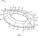
- FIG. 1 is a perspective view of a convex barrier ring having a tapered oval shape according to an embodiment
- FIG. 2 is a top view of the convex barrier ring of FIG. 1 ;
- FIG. 3 is a bottom view of the convex barrier ring of FIG. 1 ;
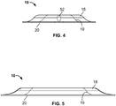
- FIG. 4 is a front view of the convex barrier ring of FIG. 1 ;
- FIG. 5 is a side view of the convex barrier ring of FIG. 1 ;
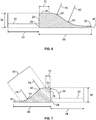
- FIG. 6 is a partial cross-sectional view of the convex barrier ring of FIG. 1 taken along line B--B of FIG. 2 ;
- FIG. 7 is a partial cross-sectional view of the convex barrier ring of FIG. 1 taken along line A--A of FIG. 2 ;
- FIG. 8 is a top view of a convex barrier ring according to another embodiment.
- FIG. 9 is a top view of a convex barrier ring according to yet another embodiment.
- a barrier ring is used to fill in or caulk uneven skin contours near a stoma and to improve seal against the stoma.
- skin folds and creases formed from various postures, for example, sitting or bending, or from obesity often reduce or break the seal around such areas and cause undesirable leakage.
- Similar seal problems also exist with patients with oval shape stomas, loop stomas, or other non-round stomas. For example, when patients with a loop stoma and/or skin folds due to obesity use a conventional round convex ring, leakage has been frequently observed around the 6 and 12 o'clock positions of the barrier ring due to reduced pressure against skin in those areas.
- convex barrier rings having a generally oval shape body with tapered peripheral end portions are provided according to various embodiments.
- a convex barrier ring 10 including an oval or elliptical stoma-receiving aperture 12 and a generally oval shaped body 11 with tapered peripheral end portions 14, 16 is illustrated according to an embodiment.
- the oval shaped stoma-receiving aperture 12 can improve the stoma fit, particularly for non-round stomas such as loop stomas and oval stomas. Further, the convexity of the body 11 and the elongated tapered peripheral end portions 14, 16 provide improved adhesion against uneven or folded or creased skin surfaces.
- the barrier ring 10 has a top surface 18 having a convex contour 19 ( FIGS. 1 , 2 , 4 and 5 ) and a flat bottom surface 20 ( FIGS. 3 , 4 and 5 ).
- the flat bottom surface 20 of the barrier ring 10 is first applied on the adhesive side of an ostomy pouch faceplate (not shown), then the ostomy pouch, assembled with the barrier ring 10, is applied about the stoma in a usual manner such that the tapered peripheral end portions 14, 16 are positioned generally horizontally to fit in the folded or creased skin.
- the top surface 18 is the surface that contacts the skin, the top surface 18 is also referred to herein as a proximal bodyside surface.
- the barrier ring 10 is formed of a suitable skin barrier material.
- the skin barrier material referred to herein may be any of the many skin barrier materials known in the art which is suitable for molding to form the barrier rings according to various embodiments.
- the barrier ring 10 is formed of a flexible medical grade adhesive material, such that the barrier ring 10 can be stretched, cut and/or stacked together to improve the fit of the ostomy pouch system.
- the barrier ring 10 can be formed of a pressure sensitive adhesive composition, such as that disclosed in US 5,492,943 assigned to the assignee of the present application, which is incorporated herein in its entirety by reference.
- the barrier ring 10 formed of such flexible materials can apply soft pressure around the stoma to improve comfort, and reduce pressure sores, hernias, and other skin conditions, such as peristomal pyoderma gangrenosum, which can result from using firm convex barrier rings. Further, the flexibility of the material allows the user to stretch or manipulate the shape of the barrier ring 10 to better fit the stoma and peristomal skin surfaces.
- the barrier ring 10 can be provided with protective coverings (not shown) on both top and bottom sides, which are removed by the user before using.
- the protective coverings can be formed of any suitable materials, such as paper or a polymeric film, and preferably coated with a release coating such as silicone.
- the illustrated convex barrier ring 10 has a generally oval shaped stoma-receiving aperture 12.
- the stoma-receiving aperture 12 is defined by an upper annular wall 26 and a lower annular wall 28.
- the upper annular wall 26 is slighted tapered.
- the annular wall 26 is sloped forming an angle 32 with a horizontal axis 30.
- the angle 32 is an obtuse angle, preferably about 95°, but may be a different angle, such as, for example, in the range of from about 85° to about 95°.
- the angle 32 may be an acute angle or the stoma-receiving aperture 12 may be defined by a single annular wall (i.e. the angle 32 may be 90°).
- the oval aperture 12 has a major radius 22 along a major axis 21 and a minor radius 24 along a minor axis 23 ( FIG. 2 ).
- the major radius 22 and the minor radius 23 are measured from the center 25 of the oval aperture to the lower annular wall 28.
- the major radius 22 is larger than the minor radius 24.
- the major radius 22 is at least about 1.2 times the minor radius 24, preferably between about 1.4 and about 1.8 times the minor radius 24.
- the convex top surface 18 of the barrier ring 10 includes a central portion 34 proximate the stoma-receiving aperture 12.
- the central portion 34 can have a generally flat surface having a cat-eye shaped perimeter 35 with a shape similar to the overall shape of the barrier ring body 11.
- the cat-eye shaped perimeter 35 terminates at tips 54, 56 at either end thereof, with end portions of the central portion 34 at 58, 60.
- the end portions 58, 60 of the central portion 34 terminate in tips.
- the central portion 34 is the thickest portion of the barrier ring 10 with a thickness 36 ( FIGS. 6 and 7 ), and thus, defines the highest point of the barrier ring 10 that can apply the most pressure around the stoma (not shown.)
- a first half 46 of the barrier ring 10 above the major axis 21 and a second half 48 below the major axis 21 are preferably symmetrical about the major axis 21.
- the top surface 18 slopes down with a curved contour 40 from the central portion 34 to a peripheral portion 38, which also has a generally flat surface.
- the curved contour 40 includes a convex portion 42 and a concave portion 44 as shown in FIGS. 1 and 7.
- FIG. 7 show a partial cross-sectional view of the first half 46 of the barrier ring 10 along line A--A ( FIG. 2 ).
- the barrier ring 10 is symmetrical about the major axis 21, a cross-sectional view of the bottom half 48 of the barrier ring 10 taken along the sectional line A--A will be the same as that shown in FIG. 2 . Further, the convex top surface 18 of each of the first half 46 and the second half 48 of the barrier ring 10 has the same curved contour 40 including the convex portion 42 and the concave portion 44. The first half 46 and the second half 48 of the barrier ring 10 meet at the elongated tapered peripheral end portions 14, 16, wherein ridges 50, 52 are formed.
- FIG. 6 shows a partial cross-sectional view of the tapered peripheral end portion 16 taken along the ridge 52 at line B--B.
- the ridges 50, 52 have a convex portion 62, and a concave portion 64.
- the barrier ring 10 is also symmetric about the minor axis 21, thus, a cross-sectional view of the tapered peripheral end portion 14 along the ridge 50 will be same as the cross-sectional view of the tapered peripheral end portion 16 shown in FIG. 6 .
- the convex barrier 10 can be made in various sizes to fit various stoma sizes and peristomal skin surfaces.
- the convex barrier ring 10 has the oval stoma-receiving aperture 12 with a major radius 22 of between about 0.5 inches and about 1.5 inches, preferably between about 0.7 inches and about 1.2 inches.
- the convex barrier ring 10 has a width 66 at the elongated tapered peripheral end portions 16 as seen along line B--B ( FIG. 6 ) of between about 0.5 inches and about 1.5 inches, preferably between about 0.8 inches and about 1.1 inches; and a width 68 as seen along line A--A ( FIG.
- the center portion 34 of the convex barrier ring 10 has a width 70 at the elongated edge 60 as seen along line B--B ( FIG. 6 ) of between about 0.15 inches and about 0.35 inches, preferably between about 0.20 inches and about 0.30 inches; and a width 72 as seen along line A--A ( FIG. 7 ) of between about 0.03 inches and about 0.12 inches, preferably between about 0.05 inches and about 0.08 inches.
- the barrier ring 10 has the thickness 36 at the center portion 34 of between about 0.15 inches and about 0.5 inches, preferably between about 0.2 inches and about 0.3 inches.
- the convex portion 42 of the curved contour 40 along line A--A has a radius 74 between about 0.15 inches and about 0.35 inches, preferably between about 0.20 inches and about 0.30 inches.
- the concave portion 44 has a radius 76 between about 0.30 inches and about 0.45 inches, preferably between about 0.35 inches and about 0.40 inches.
- the convex portion 62 of the ridge 52 along line B--B has a radius 78 between about 0.25 inches and about 0.40 inches, preferably between about 0.30 inches and about 0.35 inches.
- the concave portion 64 has a radius 80 between about 0.40 inches and about 1.10 inches, preferably between about 0.50 inches and about 0.75 inches.
- the flat peripheral portion 38 has a thickness 82 ( FIG. 6 ) of between about 0.01 inches and about 0.04 inches, preferably between about 0.015 inches and about 0.025 inches.
- FIGS. 8 and 9 show a top view of convex barrier rings 90, 92 having different sizes and dimensions according to other embodiments.
Landscapes
- Health & Medical Sciences (AREA)
- Epidemiology (AREA)
- Nursing (AREA)
- Orthopedic Medicine & Surgery (AREA)
- Engineering & Computer Science (AREA)
- Biomedical Technology (AREA)
- Heart & Thoracic Surgery (AREA)
- Vascular Medicine (AREA)
- Life Sciences & Earth Sciences (AREA)
- Animal Behavior & Ethology (AREA)
- General Health & Medical Sciences (AREA)
- Public Health (AREA)
- Veterinary Medicine (AREA)
- Orthopedics, Nursing, And Contraception (AREA)
Abstract
Description
- This application claims the benefit of priority of Provisional
U.S. Patent Application Serial No. 61/449,937, filed March 7, 2011 - The present disclosure relates to a skin barrier for ostomy appliances, and more particularly to an oval shaped convex barrier ring.
- Barrier rings are used with ostomy appliances to aid in sealing such appliances against peristomal skin surfaces and thereby protect those surfaces from exposure to stomal effluent as well as to prevent leakage of the effluent from about stoma-receiving openings of the pouches. However, the topography of stomas and peristomal surfaces surrounding stomas vary among patients, and sealing the ostomy appliances against such different peristomal surfaces and stomas remain as an area for further improvements.
- For example, a stoma may protrude more or less, or may even be flush or recessed. Ostomy patients with flush or recessed stomas have found that if external pressure is applied in the peristomal region, sufficient protrusion of the stoma may occur to aid in the discharge of effluent directly into the collection pouch, thereby prolonging the effectiveness of the adhesive seal between the faceplate and the peristomal skin surface. Skin irritation and patient discomfort may also be greatly reduced. Thus, convex inserts and convex pressure rings, such as ADAPT® convex barrier rings available through the assignee of the present application, have been developed to apply pressure around such peristomal region.
- Because of the inherent severe medical, social, economical and personal concerns related to the need for use of an ostomy appliance, improvements in barrier rings to provide better sealing function and/or comfort is an important factor in the quality of life of wearers and therefore in the consequent health and psychological aspects of the wearer. Any appreciable improvement of such ostomy appliances is therefore of great importance to the increasing number of such wearers. The present disclosure provides improved convex barrier rings according to various embodiments to enhance comfort and sealing between the peristomal skin surfaces and the ostomy appliances.
- Barrier rings according to various embodiments have a convex surface contour and a generally oval peripheral shape to provide improved sealing of ostomy appliances against peristomal surfaces. Further, the barrier rings can have an oval shaped stoma-receiving aperture to apply even pressure on the peristomal surfaces surrounding non-round stomas such as oval and loop stomas. Preferably, the convex oval barrier rings have tapered peripheral end portions, which can aid in sealing the ostomy appliances against folded or creased skin surfaces.
- In one aspect, a barrier ring for attaching an ostomy appliance to a peristomal skin surrounding a stoma is provided. The barrier ring includes a generally oval shaped body with tapered peripheral end portions, a convex proximal bodyside surface, a flat bottom surface, and a stoma-receiving aperture.
- In another aspect, a convex barrier ring for attaching an ostomy appliance to peristomal skin surrounding a stoma includes a convex proximal bodyside surface, a flat bottom surface, an oval stoma-receiving aperture, and a cat-eye shaped body having elongated peripheral end portions. The elongated peripheral end portions may include ridges.
- In yet another aspect, a barrier ring for attaching an ostomy appliance to a peristomal skin surrounding a stoma is provided. The barrier ring includes a generally oval shaped body with tapered peripheral end portions defining a major axis and a minor axis, a bodyside surface, a bottom surface, and a stoma-receiving aperture. The bodyside surface, when viewed in a cross-section taken along the major axis defines a convex surface transitioning to a concave surface from the stoma-receiving aperture to a respective tapered peripheral end portion.
- In another aspect, a method of attaching an ostomy appliance to peristomal folded or creased skin surfaces surrounding a stoma of a wearer is provided. The method includes providing a convex barrier ring that includes a convex proximal bodyside surface, a flat bottom surface, an oval stoma-receiving aperture, and a cat-eye shaped body having elongated peripheral end portions, wherein the elongated peripheral end portions include ridges. Further, the method includes placing the flat bottom surface on an adhesive side of a faceplate of the ostomy appliance, arranging the ostomy appliance assembled with the convex barrier ring around the stoma such that the stoma is arranged in the oval stoma-receiving aperture, and sealing the convex proximal bodyside surface against the peristomal skin surfaces such that the elongated peripheral end portions are aligned with the skin folds or creases.
- Other aspects, objectives and advantages will become more apparent from the following detailed description when taken in conjunction with the accompanying drawings.
- The benefits and advantages of the present embodiments will become more readily apparent to those of ordinary skill in the relevant art after reviewing the following detailed description and accompanying drawings, wherein:
-
FIG. 1 is a perspective view of a convex barrier ring having a tapered oval shape according to an embodiment; -
FIG. 2 is a top view of the convex barrier ring ofFIG. 1 ; -
FIG. 3 is a bottom view of the convex barrier ring ofFIG. 1 ; -
FIG. 4 is a front view of the convex barrier ring ofFIG. 1 ; -
FIG. 5 is a side view of the convex barrier ring ofFIG. 1 ; -
FIG. 6 is a partial cross-sectional view of the convex barrier ring ofFIG. 1 taken along line B--B ofFIG. 2 ; -
FIG. 7 is a partial cross-sectional view of the convex barrier ring ofFIG. 1 taken along line A--A ofFIG. 2 ; -
FIG. 8 is a top view of a convex barrier ring according to another embodiment; and -
FIG. 9 is a top view of a convex barrier ring according to yet another embodiment. - While the present disclosure is susceptible of embodiment in various forms, there is shown in the drawings and will hereinafter be described a presently preferred embodiment with the understanding that the present disclosure is to be considered an exemplification and is not intended to limit the disclosure to the specific embodiment illustrated.
- A barrier ring is used to fill in or caulk uneven skin contours near a stoma and to improve seal against the stoma. However, skin folds and creases formed from various postures, for example, sitting or bending, or from obesity, often reduce or break the seal around such areas and cause undesirable leakage. Similar seal problems also exist with patients with oval shape stomas, loop stomas, or other non-round stomas. For example, when patients with a loop stoma and/or skin folds due to obesity use a conventional round convex ring, leakage has been frequently observed around the 6 and 12 o'clock positions of the barrier ring due to reduced pressure against skin in those areas.
- To overcome this problem, convex barrier rings having a generally oval shape body with tapered peripheral end portions are provided according to various embodiments. In
FIGS. 1-7 , aconvex barrier ring 10 including an oval or elliptical stoma-receivingaperture 12 and a generally oval shapedbody 11 with taperedperipheral end portions shaped body 11 that tapers at either side to terminate in the taperedperipheral end portions body 11 in plan view resembles a cat-eye (see e.g.FIGS. 2 and 3 ), thus the barrier rings having such a shape are also referred to herein as cat-eye barrier rings. The oval shaped stoma-receivingaperture 12 can improve the stoma fit, particularly for non-round stomas such as loop stomas and oval stomas. Further, the convexity of thebody 11 and the elongated taperedperipheral end portions - The
barrier ring 10 has atop surface 18 having a convex contour 19 (FIGS. 1 ,2 ,4 and 5 ) and a flat bottom surface 20 (FIGS. 3 ,4 and 5 ). In use, theflat bottom surface 20 of thebarrier ring 10 is first applied on the adhesive side of an ostomy pouch faceplate (not shown), then the ostomy pouch, assembled with thebarrier ring 10, is applied about the stoma in a usual manner such that the taperedperipheral end portions top surface 18 is the surface that contacts the skin, thetop surface 18 is also referred to herein as a proximal bodyside surface. - The
barrier ring 10 is formed of a suitable skin barrier material. The skin barrier material referred to herein may be any of the many skin barrier materials known in the art which is suitable for molding to form the barrier rings according to various embodiments. Preferably, thebarrier ring 10 is formed of a flexible medical grade adhesive material, such that thebarrier ring 10 can be stretched, cut and/or stacked together to improve the fit of the ostomy pouch system. For example, thebarrier ring 10 can be formed of a pressure sensitive adhesive composition, such as that disclosed inUS 5,492,943 assigned to the assignee of the present application, which is incorporated herein in its entirety by reference. Thebarrier ring 10 formed of such flexible materials can apply soft pressure around the stoma to improve comfort, and reduce pressure sores, hernias, and other skin conditions, such as peristomal pyoderma gangrenosum, which can result from using firm convex barrier rings. Further, the flexibility of the material allows the user to stretch or manipulate the shape of thebarrier ring 10 to better fit the stoma and peristomal skin surfaces. - The
barrier ring 10 can be provided with protective coverings (not shown) on both top and bottom sides, which are removed by the user before using. The protective coverings can be formed of any suitable materials, such as paper or a polymeric film, and preferably coated with a release coating such as silicone. - Referring again to
FIGS. 1-7 , the illustratedconvex barrier ring 10 has a generally oval shaped stoma-receivingaperture 12. The stoma-receivingaperture 12 is defined by an upperannular wall 26 and a lowerannular wall 28. As shown in partial cross-sectional views of the barrier ring 10 (FIGS. 6 and 7 ), the upperannular wall 26 is slighted tapered. Theannular wall 26 is sloped forming anangle 32 with ahorizontal axis 30. In this embodiment theangle 32 is an obtuse angle, preferably about 95°, but may be a different angle, such as, for example, in the range of from about 85° to about 95°. In other embodiments, theangle 32 may be an acute angle or the stoma-receivingaperture 12 may be defined by a single annular wall (i.e. theangle 32 may be 90°). Theoval aperture 12 has amajor radius 22 along amajor axis 21 and aminor radius 24 along a minor axis 23 (FIG. 2 ). Themajor radius 22 and theminor radius 23 are measured from thecenter 25 of the oval aperture to the lowerannular wall 28. Themajor radius 22 is larger than theminor radius 24. In this embodiment, themajor radius 22 is at least about 1.2 times theminor radius 24, preferably between about 1.4 and about 1.8 times theminor radius 24. - The convex
top surface 18 of thebarrier ring 10 includes acentral portion 34 proximate the stoma-receivingaperture 12. Thecentral portion 34 can have a generally flat surface having a cat-eye shapedperimeter 35 with a shape similar to the overall shape of thebarrier ring body 11. The cat-eye shapedperimeter 35 terminates attips central portion 34 at 58, 60. Theend portions central portion 34 terminate in tips. Thecentral portion 34 is the thickest portion of thebarrier ring 10 with a thickness 36 (FIGS. 6 and 7 ), and thus, defines the highest point of thebarrier ring 10 that can apply the most pressure around the stoma (not shown.) - A
first half 46 of thebarrier ring 10 above themajor axis 21 and asecond half 48 below themajor axis 21 are preferably symmetrical about themajor axis 21. Thetop surface 18 slopes down with acurved contour 40 from thecentral portion 34 to aperipheral portion 38, which also has a generally flat surface. Thecurved contour 40 includes aconvex portion 42 and aconcave portion 44 as shown inFIGS. 1 and7. FIG. 7 show a partial cross-sectional view of thefirst half 46 of thebarrier ring 10 along line A--A (FIG. 2 ). Since thebarrier ring 10 is symmetrical about themajor axis 21, a cross-sectional view of thebottom half 48 of thebarrier ring 10 taken along the sectional line A--A will be the same as that shown inFIG. 2 . Further, the convextop surface 18 of each of thefirst half 46 and thesecond half 48 of thebarrier ring 10 has the samecurved contour 40 including theconvex portion 42 and theconcave portion 44. Thefirst half 46 and thesecond half 48 of thebarrier ring 10 meet at the elongated taperedperipheral end portions ridges - As shown in
FIGS. 1 and2 , theridges tips center portion 34 to theperipheral portion 38 of the taperedperipheral end portions FIG. 6 shows a partial cross-sectional view of the taperedperipheral end portion 16 taken along theridge 52 at line B--B. As shown inFIG. 6 , theridges convex portion 62, and aconcave portion 64. Thebarrier ring 10 is also symmetric about theminor axis 21, thus, a cross-sectional view of the taperedperipheral end portion 14 along theridge 50 will be same as the cross-sectional view of the taperedperipheral end portion 16 shown inFIG. 6 . - The
convex barrier 10 can be made in various sizes to fit various stoma sizes and peristomal skin surfaces. In one embodiment, theconvex barrier ring 10 has the oval stoma-receivingaperture 12 with amajor radius 22 of between about 0.5 inches and about 1.5 inches, preferably between about 0.7 inches and about 1.2 inches. Theconvex barrier ring 10 has awidth 66 at the elongated taperedperipheral end portions 16 as seen along line B--B (FIG. 6 ) of between about 0.5 inches and about 1.5 inches, preferably between about 0.8 inches and about 1.1 inches; and awidth 68 as seen along line A--A (FIG. 7 ) of between about 0.3 inches and about 1.0 inches, and preferably between about 0.5 inches and about 0.8 inches. Thecenter portion 34 of theconvex barrier ring 10 has awidth 70 at theelongated edge 60 as seen along line B--B (FIG. 6 ) of between about 0.15 inches and about 0.35 inches, preferably between about 0.20 inches and about 0.30 inches; and awidth 72 as seen along line A--A (FIG. 7 ) of between about 0.03 inches and about 0.12 inches, preferably between about 0.05 inches and about 0.08 inches. Thebarrier ring 10 has thethickness 36 at thecenter portion 34 of between about 0.15 inches and about 0.5 inches, preferably between about 0.2 inches and about 0.3 inches. - Further, in the illustrated embodiment, the
convex portion 42 of thecurved contour 40 along line A--A (FIG. 7 ) has aradius 74 between about 0.15 inches and about 0.35 inches, preferably between about 0.20 inches and about 0.30 inches. Theconcave portion 44 has aradius 76 between about 0.30 inches and about 0.45 inches, preferably between about 0.35 inches and about 0.40 inches. Theconvex portion 62 of theridge 52 along line B--B (FIG. 6 ) has aradius 78 between about 0.25 inches and about 0.40 inches, preferably between about 0.30 inches and about 0.35 inches. Theconcave portion 64 has aradius 80 between about 0.40 inches and about 1.10 inches, preferably between about 0.50 inches and about 0.75 inches. The flatperipheral portion 38 has a thickness 82 (FIG. 6 ) of between about 0.01 inches and about 0.04 inches, preferably between about 0.015 inches and about 0.025 inches.FIGS. 8 and 9 show a top view of convex barrier rings 90, 92 having different sizes and dimensions according to other embodiments. - Dimensional details of three preferred embodiments of the
convex barrier ring 10 are provided below in Table 1. - Table 1 Convex Oval Barrier Ring Examples
Dimensions (Reference numbers correspond to FIGS. 1-7 )Example 1 (inches) Example 2 (inches) Example 3 (inches) Major radius 22 - oval stoma-receiving aperture 0.945 0.748 1.102 Minor radius 24 - oval stoma-receiving aperture 0.591 0.433 0.748 Barrier width 66 along major axis1.034 0.981 0.894 Barrier width 68 along minor axis0.670 0.670 0.670 Center portion width 70 along major axis0.272 0.219 0.230 Center portion width 72 along minor axis0.068 0.068 0.068 Radius 78 ofconvex portion 62 along major axis0.340 0.339 0.302 Radius 80 ofconcave portion 64 along major axis0.724 0.724 0.578 Radius 74 ofconvex portion 42 along minor axis0.250 0.250 0.250 Radius 76 ofconcave portion 44 along minor axis0.375 0.375 0.375 Thickness 82 of barrier at peripheral portion0.020 0.020 0.020 Thickness 36 of barrier at center portion0.250 0.250 0.250 - All patents referred to herein, are hereby incorporated herein in their entirety, by reference, whether or not specifically indicated as such within the text of this disclosure.
- In the present disclosure, the words "a" or "an" are to be taken to include both the singular and the plural. Conversely, any reference to plural items shall, where appropriate, include the singular.
- From the foregoing it will be observed that numerous modifications and variations can be effectuated without departing from the true spirit and scope of the novel concepts of the present invention. It is to be understood that no limitation with respect to the specific embodiments illustrated is intended or should be inferred. The disclosure is intended to cover by the appended claims all such modifications as fall within the scope of the claims.
Claims (15)
- A barrier ring for attaching an ostomy appliance to a peristomal skin surrounding a stoma, the barrier ring comprising:a generally oval shaped body with tapered peripheral end portions;a convex proximal bodyside surface;a flat bottom surface; anda stoma-receiving aperture;wherein the bodyside surface, when viewed in a cross-section taken along the major axis defines a convex surface transitioning to a concave surface from the stoma-receiving aperture to a respective tapered peripheral end portion.
- The barrier ring of claim 1, further defining a major axis and a minor axis,
wherein the barrier ring is symmetrical about the major axis and the minor axis, and wherein the tapered peripheral end portions are arranged along the major axis, and wherein the tapered peripheral end portions include ridges, and wherein the ridges are configured to fit in skin folds or creases to improve a seal between the barrier ring and the peristomal skin. - The barrier ring of claim 1, wherein the stoma-receiving aperture defines an oval shaped periphery, wherein a major radius of the stoma-receiving aperture is greater than about 1.2 times a minor radius.
- A convex barrier ring for attaching an ostomy appliance to a peristomal skin surrounding a stoma, the convex barrier ring comprising:a convex proximal bodyside surface;a flat bottom surface;an oval stoma-receiving aperture; anda cat-eye shaped body having elongated peripheral end portions, wherein the elongated peripheral end portions include ridges.
- The convex barrier ring of claim 4, wherein the oval stoma-receiving aperture has a major radius and a minor radius, and wherein the major radius is between about 1.4 and about 1.8 times the minor radius.
- The convex barrier ring of any of claims 1-5, wherein the convex proximal bodyside surface includes a center portion proximate the stoma-receiving aperture, a peripheral portion, and a surface extending down from the center portion to the peripheral portion with a curved contour.
- The convex barrier ring of claim 6, wherein the curved contour includes a convex portion and a concave portion.
- The convex barrier ring of claim 6, wherein the center portion has a cat-eye shaped periphery having elongated peripheral end portions, wherein the each of the ridges extends down from a tip of each of the elongated peripheral end portions of the center portion to the peripheral portion.
- The convex barrier ring of claim 4, wherein a contour of the convex proximal bodyside surface is symmetrical about a major axis and about a minor axis.
- The convex barrier ring of any of claims 1-9, wherein the convex barrier ring is formed of a skin barrier material.
- The convex barrier ring of any of claims 1-10, wherein the skin barrier material is a pressure sensitive adhesive composition.
- The barrier ring of any of claims 1-11, wherein a cross-section taken along the minor axis defines a convex surface transitioning to a concave surface from the stoma-receiving aperture to a respective peripheral portion of the barrier ring.
- A method of attaching an ostomy appliance to peristomal folded or creased skin surfaces surrounding a stoma of a wearer, the method comprising:providing a convex barrier ring comprising:a convex proximal bodyside surface;a flat bottom surface;an oval stoma-receiving aperture; anda cat-eye shaped body having elongated peripheral end portions, wherein the elongated peripheral end portions include ridges;placing the flat bottom surface on an adhesive side of a faceplate of the ostomy appliance;arranging the ostomy appliance assembled with the convex barrier ring around the stoma such that the stoma is arranged in the oval stoma-receiving aperture;sealing the convex proximal bodyside surface against the peristomal skin surfaces such that the elongated peripheral end portions are aligned with the skin folds or creases.
- The method of claim 13, further comprising selecting a convex barrier ring according a topography of the stoma and the peristomal skin surfaces.
- The method of claim 14, wherein sealing the convex proximal bodyside surface includes aligning the elongated peripheral end portions such that the ridges are arranged in the skin folds or creases to improve the seal between the barrier ring and the peristomal skin surfaces and to reduce leakage.
Applications Claiming Priority (2)
| Application Number | Priority Date | Filing Date | Title |
|---|---|---|---|
| US201161449937P | 2011-03-07 | 2011-03-07 | |
| US13/402,558 US8672908B2 (en) | 2011-03-07 | 2012-02-22 | Convex barrier ring |
Publications (3)
| Publication Number | Publication Date |
|---|---|
| EP2497449A2 true EP2497449A2 (en) | 2012-09-12 |
| EP2497449A3 EP2497449A3 (en) | 2012-12-26 |
| EP2497449B1 EP2497449B1 (en) | 2016-01-06 |
Family
ID=45877973
Family Applications (1)
| Application Number | Title | Priority Date | Filing Date |
|---|---|---|---|
| EP12158016.1A Active EP2497449B1 (en) | 2011-03-07 | 2012-03-05 | Convex barrier ring |
Country Status (7)
| Country | Link |
|---|---|
| US (1) | US8672908B2 (en) |
| EP (1) | EP2497449B1 (en) |
| JP (1) | JP5567614B2 (en) |
| AU (1) | AU2012201338B2 (en) |
| CA (1) | CA2769944C (en) |
| DK (1) | DK2497449T3 (en) |
| HU (1) | HUE027131T2 (en) |
Cited By (6)
| Publication number | Priority date | Publication date | Assignee | Title |
|---|---|---|---|---|
| WO2014121921A1 (en) * | 2013-02-05 | 2014-08-14 | Andreas Fahl Medizintechnik-Vertrieb Gmbh | Tracheostoma plaster |
| EP2904996A1 (en) * | 2014-02-11 | 2015-08-12 | T.G. Eakin Limited | Seal for use with a stoma |
| EP3060136A4 (en) * | 2013-10-18 | 2017-06-21 | Lightside Md, Llc | Support devices and methods of making and using them |
| US10335322B2 (en) | 2013-08-26 | 2019-07-02 | Lightside Md, Llc | Adhesive support devices and methods of making and using them |
| WO2020200382A1 (en) | 2019-04-01 | 2020-10-08 | Coloplast A/S | A pliable skin barrier ring |
| US12097142B2 (en) | 2022-09-01 | 2024-09-24 | Hollister Incorporated | Ostomy appliance with customizable barrier ring for localized convex support |
Families Citing this family (15)
| Publication number | Priority date | Publication date | Assignee | Title |
|---|---|---|---|---|
| GB2473667B (en) * | 2009-09-22 | 2015-11-18 | Salts Healthcare Ltd | Adhesive member |
| EP3270835B1 (en) | 2015-03-16 | 2019-05-08 | Coloplast A/S | Ostomy device |
| ES2808860T3 (en) * | 2015-09-11 | 2021-03-02 | Coloplast As | Ostomy device |
| US10945873B2 (en) | 2016-05-12 | 2021-03-16 | Marlen Manufacturing And Development Co. | Multi-petaled mounting members for ostomy pouches |
| USD862691S1 (en) | 2016-05-12 | 2019-10-08 | Marlen Manufacturing And Development Co. | Ostomy pouch |
| EP3454797B1 (en) | 2016-05-12 | 2022-02-09 | Marlen Manufacturing And Development Co. | Mounting assemblies for ostomy appliances comprising an adhesive skin barrier member having a multi-petaled outer perimeter |
| USD899613S1 (en) * | 2017-12-15 | 2020-10-20 | Perfect Fit Brand, Inc. | Thrust bumper |
| WO2019120448A1 (en) * | 2017-12-22 | 2019-06-27 | Coloplast A/S | System including a skin-engageable element of an ostomy appliance |
| WO2020220025A1 (en) * | 2019-04-25 | 2020-10-29 | Convatec Technologies Inc. | Ostomy wafers incorporating adhesives and foam layers, devices including the same, and methods of applying |
| AU2020262496A1 (en) * | 2019-04-25 | 2021-11-18 | Convatec Technologies Inc. | Ostomy wafers incorporating adhesives, ostomy devices including the same, and methods of applying |
| EP3946178B1 (en) * | 2019-04-25 | 2025-03-26 | ConvaTec Technologies Inc. | Perforated chamber ostomy wafers |
| US11590018B2 (en) * | 2019-05-14 | 2023-02-28 | Medline Industries, Lp | Fecal management applicator and assembly |
| EP4069163A1 (en) * | 2019-12-06 | 2022-10-12 | Hollister Incorporated | Soft convex ostomy appliance |
| WO2023076382A1 (en) * | 2021-10-27 | 2023-05-04 | Hollister Incorporated | Method for scanning stoma and peristomal topography and generating representations of same |
| CA3207325C (en) | 2022-09-01 | 2024-01-02 | James P. WINES | Ostomy appliance for providing customized and localized convex support |
Citations (1)
| Publication number | Priority date | Publication date | Assignee | Title |
|---|---|---|---|---|
| US5492943A (en) | 1994-06-20 | 1996-02-20 | Hollister Incorporated | Adhesive skin barrier composition for ostomy appliance |
Family Cites Families (47)
| Publication number | Priority date | Publication date | Assignee | Title |
|---|---|---|---|---|
| US3076458A (en) | 1960-12-22 | 1963-02-05 | James H Mason | Surgical appliance |
| US3557790A (en) | 1967-11-28 | 1971-01-26 | Raul C Hauser | Ileostomy and like appliances |
| US4109657A (en) | 1976-10-19 | 1978-08-29 | Carrington Russell Settle | Body profiled surgical drainage appliance |
| AU524110B2 (en) | 1978-06-16 | 1982-09-02 | Bird Appliances Limited | Ostomy plug |
| JPS55122712U (en) * | 1979-02-23 | 1980-09-01 | ||
| JP3164475B2 (en) | 1994-04-22 | 2001-05-08 | 住友ベークライト株式会社 | Fistula test tool |
| NZ314490A (en) | 1996-04-10 | 1998-12-23 | Bristol Myers Squibb Co | Customised ostomy device and manufacture thereof - measuring, electronic recording and fabricating an adhesive wafer and collection pouch |
| US5811116A (en) * | 1996-04-30 | 1998-09-22 | Hollister Incorporated | Adhesive wafer with embossed skin-contacting surface |
| US5730736A (en) * | 1996-04-30 | 1998-03-24 | Dansac A/S | Ostomy appliance and contoured adhesive wafer therefor |
| DK0981311T3 (en) | 1997-04-08 | 2004-12-20 | Coloplast As | An ostomy appliance |
| US6350256B1 (en) * | 1997-06-28 | 2002-02-26 | The Procter & Gamble Co. | Shaped skin attachment means for a faecal collector |
| US6485476B1 (en) | 1998-02-25 | 2002-11-26 | Zassi Medical Evolutions, Inc. | Continent ostomy port |
| US6350255B1 (en) | 1998-02-25 | 2002-02-26 | Zassi Medical Evolutions, Inc. | Pad for use with a continent ostomy port |
| US7087041B2 (en) | 1998-02-25 | 2006-08-08 | Zassi Medical Evolutions, Inc. | Pad for use with continent ostomy port |
| US6033390A (en) | 1998-02-25 | 2000-03-07 | Zassi Medical Evolutions, Inc. | Continent ostomy port |
| US6491673B1 (en) | 1998-06-26 | 2002-12-10 | The Procter & Gamble Company | Disposable urine collector |
| US6508794B1 (en) | 1998-06-26 | 2003-01-21 | The Procter & Gamble Company | Method for collecting and disposing of human waste |
| US6464674B1 (en) | 1999-06-11 | 2002-10-15 | The Procter & Gamble Company | Adhesive urine collector with optimal aperture |
| US6551292B1 (en) | 1999-06-28 | 2003-04-22 | The Procter & Gamble Company | Shaped flange for a urine collector |
| US6740067B2 (en) | 2000-06-14 | 2004-05-25 | Hollister Incorporated | Reformable convex adapter for ostomy appliance |
| US6569134B1 (en) * | 2000-06-14 | 2003-05-27 | Hollister Incorporated | Reformable convex adapter for ostomy appliance and method of use |
| US6916312B2 (en) | 2001-08-31 | 2005-07-12 | The Procter & Gamble Company | Applicator for excreta management device |
| DK175870B1 (en) | 2001-09-05 | 2005-05-02 | Coloplast As | An ostomy appliance |
| US6673056B2 (en) | 2001-11-05 | 2004-01-06 | Hollister Incorporated | Snap-in insert for convex ostomy faceplate |
| EP1474083B1 (en) | 2002-02-14 | 2010-01-06 | The Procter & Gamble Company | Disposable excreta collector |
| US20030171737A1 (en) | 2002-03-11 | 2003-09-11 | Leise, Walter F. | Soft convex adhesive wafer |
| US6926701B2 (en) | 2002-07-01 | 2005-08-09 | The Proctor & Gamble Company | Disposable excreta management device |
| US20040087920A1 (en) | 2002-10-28 | 2004-05-06 | Etheredge Robert W. | Ostomy device kit |
| DK176790B1 (en) | 2003-03-31 | 2009-09-07 | Coloplast As | Sticky patch |
| DE20307688U1 (en) | 2003-05-16 | 2003-07-31 | For Life Produktions- und Vertriebsgesellschaft für Heil- und Hilfsmittel mbH, 12459 Berlin | Convex fastener, to secure a one- or two-piece colostomy bag to the colon outflow, has an adhesive surface at the flange to attach to the colon skin with elliptical interface surfaces and an elliptical center opening |
| ATE424793T1 (en) | 2003-09-18 | 2009-03-15 | Braun Medical Sas | CONNECTING OSTOMY DEVICE |
| WO2005041828A2 (en) | 2003-10-21 | 2005-05-12 | Hollister Incorporated | Peelable and flushable ostomy pouch and method of use |
| US20050177119A1 (en) | 2004-01-21 | 2005-08-11 | Tsai M. L. | Pouch for medical use |
| WO2006002634A1 (en) | 2004-06-30 | 2006-01-12 | Coloplast A/S | Skin plate adhesive product and method for its manufacture |
| WO2006035014A2 (en) | 2004-09-29 | 2006-04-06 | Coloplast A/S | A resalable ostomy appliance |
| WO2006090093A1 (en) | 2005-02-25 | 2006-08-31 | Gaffney, Edward | An improved bag for use by a subject following a surgical procedure during which a stoma is formed |
| EP1966340B1 (en) | 2005-12-23 | 2012-12-05 | Coloplast A/S | Hydractive recipe |
| US8070737B2 (en) | 2006-01-06 | 2011-12-06 | Convatec Technologies Inc. | Seal for controlled evacuation ostomy appliance |
| EP1894547A1 (en) | 2006-08-29 | 2008-03-05 | Eurotec Beheer B.V. | Ostomy coupling |
| US7927320B2 (en) | 2006-09-20 | 2011-04-19 | Tisteron, Ltd. | Disposable waste containment article and a combination of two articles worn simultaneously |
| US20090234312A1 (en) | 2007-04-24 | 2009-09-17 | O'toole Lois Diane | Ostomy Pouch |
| ES2310487B1 (en) | 2007-06-26 | 2009-08-04 | Antonio Del Pino Aragones | STOMAS PROTECTOR. |
| ATE486554T1 (en) | 2007-08-09 | 2010-11-15 | Hollister Inc | DRAINABLE OSTOMY BAG WITH FLEXIBLE STIFFENING STRIPS WITH MULTIPLE GROOVES |
| CN102215789B (en) * | 2008-11-12 | 2014-07-16 | 科洛普拉斯特公司 | To control bending in a skin plate for use in an ostomy appliance |
| US8211073B2 (en) * | 2009-06-17 | 2012-07-03 | Hollister Incorporated | Ostomy faceplate having moldable adhesive wafer with diminishing surface undulations |
| EP2496193B1 (en) | 2009-11-02 | 2015-03-11 | Coloplast A/S | Seal for an ostomy appliance |
| RU2571326C2 (en) | 2010-12-17 | 2015-12-20 | Колопласт А/С | Convex support device for stoma formation |
-
2012
- 2012-02-22 US US13/402,558 patent/US8672908B2/en active Active
- 2012-02-28 CA CA2769944A patent/CA2769944C/en active Active
- 2012-03-05 EP EP12158016.1A patent/EP2497449B1/en active Active
- 2012-03-05 HU HUE12158016A patent/HUE027131T2/en unknown
- 2012-03-05 DK DK12158016.1T patent/DK2497449T3/en active
- 2012-03-06 AU AU2012201338A patent/AU2012201338B2/en active Active
- 2012-03-07 JP JP2012050333A patent/JP5567614B2/en active Active
Patent Citations (1)
| Publication number | Priority date | Publication date | Assignee | Title |
|---|---|---|---|---|
| US5492943A (en) | 1994-06-20 | 1996-02-20 | Hollister Incorporated | Adhesive skin barrier composition for ostomy appliance |
Cited By (9)
| Publication number | Priority date | Publication date | Assignee | Title |
|---|---|---|---|---|
| WO2014121921A1 (en) * | 2013-02-05 | 2014-08-14 | Andreas Fahl Medizintechnik-Vertrieb Gmbh | Tracheostoma plaster |
| US10300233B2 (en) | 2013-02-05 | 2019-05-28 | Andreas Fahl Medizintechnik-Vertrieb Gmbh | Tracheostoma plaster |
| US10335322B2 (en) | 2013-08-26 | 2019-07-02 | Lightside Md, Llc | Adhesive support devices and methods of making and using them |
| US11141319B2 (en) | 2013-08-26 | 2021-10-12 | Lightside Md, Llc | Adhesive support devices |
| EP3060136A4 (en) * | 2013-10-18 | 2017-06-21 | Lightside Md, Llc | Support devices and methods of making and using them |
| US10786652B2 (en) | 2013-10-18 | 2020-09-29 | Lightside Md, Llc | Support devices and methods of making and using them |
| EP2904996A1 (en) * | 2014-02-11 | 2015-08-12 | T.G. Eakin Limited | Seal for use with a stoma |
| WO2020200382A1 (en) | 2019-04-01 | 2020-10-08 | Coloplast A/S | A pliable skin barrier ring |
| US12097142B2 (en) | 2022-09-01 | 2024-09-24 | Hollister Incorporated | Ostomy appliance with customizable barrier ring for localized convex support |
Also Published As
| Publication number | Publication date |
|---|---|
| DK2497449T3 (en) | 2016-04-04 |
| EP2497449B1 (en) | 2016-01-06 |
| US20120232506A1 (en) | 2012-09-13 |
| JP2012183315A (en) | 2012-09-27 |
| US8672908B2 (en) | 2014-03-18 |
| AU2012201338B2 (en) | 2013-09-12 |
| CA2769944A1 (en) | 2012-09-07 |
| HUE027131T2 (en) | 2016-10-28 |
| EP2497449A3 (en) | 2012-12-26 |
| JP5567614B2 (en) | 2014-08-06 |
| CA2769944C (en) | 2014-11-25 |
| AU2012201338A1 (en) | 2012-09-20 |
Similar Documents
| Publication | Publication Date | Title |
|---|---|---|
| EP2497449B1 (en) | Convex barrier ring | |
| US12589023B2 (en) | Convex ostomy barrier and method of forming convex ostomy barriers of various softness | |
| DK2974702T3 (en) | FOR MANAGING THE CURVENCE OF A SKIN PLATE FOR USE IN A STOMI DEVICE | |
| US20030171737A1 (en) | Soft convex adhesive wafer | |
| CN102655827B (en) | Seal for an ostomy appliance | |
| US8512303B2 (en) | Negative drawstring seal for an ostomy bag | |
| CA3041083C (en) | Convex ostomy barrier | |
| CN106456352A (en) | An ostomy wafer | |
| JP2002537067A (en) | Ostomy appliances | |
| JP2025514108A (en) | Ostomy barrier device with self-actuating adjustable protrusions | |
| CA3108574C (en) | Convex ostomy barrier and method of forming convex ostomy barriers of various softness | |
| US12097142B2 (en) | Ostomy appliance with customizable barrier ring for localized convex support | |
| WO2025259495A1 (en) | Concave barrier ring or strip | |
| WO2025014630A1 (en) | Convex ostomy barrier with flexible support convexity |
Legal Events
| Date | Code | Title | Description |
|---|---|---|---|
| PUAI | Public reference made under article 153(3) epc to a published international application that has entered the european phase |
Free format text: ORIGINAL CODE: 0009012 |
|
| AK | Designated contracting states |
Kind code of ref document: A2 Designated state(s): AL AT BE BG CH CY CZ DE DK EE ES FI FR GB GR HR HU IE IS IT LI LT LU LV MC MK MT NL NO PL PT RO RS SE SI SK SM TR |
|
| AX | Request for extension of the european patent |
Extension state: BA ME |
|
| RIC1 | Information provided on ipc code assigned before grant |
Ipc: A61F 5/443 20060101AFI20120927BHEP Ipc: A61F 5/445 20060101ALI20120927BHEP |
|
| PUAL | Search report despatched |
Free format text: ORIGINAL CODE: 0009013 |
|
| AK | Designated contracting states |
Kind code of ref document: A3 Designated state(s): AL AT BE BG CH CY CZ DE DK EE ES FI FR GB GR HR HU IE IS IT LI LT LU LV MC MK MT NL NO PL PT RO RS SE SI SK SM TR |
|
| AX | Request for extension of the european patent |
Extension state: BA ME |
|
| RIC1 | Information provided on ipc code assigned before grant |
Ipc: A61F 5/443 20060101AFI20121119BHEP Ipc: A61F 5/445 20060101ALI20121119BHEP |
|
| 17P | Request for examination filed |
Effective date: 20130621 |
|
| RBV | Designated contracting states (corrected) |
Designated state(s): AL AT BE BG CH CY CZ DE DK EE ES FI FR GB GR HR HU IE IS IT LI LT LU LV MC MK MT NL NO PL PT RO RS SE SI SK SM TR |
|
| GRAP | Despatch of communication of intention to grant a patent |
Free format text: ORIGINAL CODE: EPIDOSNIGR1 |
|
| INTG | Intention to grant announced |
Effective date: 20150623 |
|
| GRAS | Grant fee paid |
Free format text: ORIGINAL CODE: EPIDOSNIGR3 |
|
| GRAA | (expected) grant |
Free format text: ORIGINAL CODE: 0009210 |
|
| AK | Designated contracting states |
Kind code of ref document: B1 Designated state(s): AL AT BE BG CH CY CZ DE DK EE ES FI FR GB GR HR HU IE IS IT LI LT LU LV MC MK MT NL NO PL PT RO RS SE SI SK SM TR |
|
| REG | Reference to a national code |
Ref country code: GB Ref legal event code: FG4D |
|
| REG | Reference to a national code |
Ref country code: CH Ref legal event code: EP |
|
| REG | Reference to a national code |
Ref country code: IE Ref legal event code: FG4D |
|
| REG | Reference to a national code |
Ref country code: AT Ref legal event code: REF Ref document number: 768202 Country of ref document: AT Kind code of ref document: T Effective date: 20160215 |
|
| REG | Reference to a national code |
Ref country code: DE Ref legal event code: R096 Ref document number: 602012013556 Country of ref document: DE |
|
| REG | Reference to a national code |
Ref country code: FR Ref legal event code: PLFP Year of fee payment: 5 |
|
| REG | Reference to a national code |
Ref country code: DK Ref legal event code: T3 Effective date: 20160331 |
|
| REG | Reference to a national code |
Ref country code: NL Ref legal event code: FP |
|
| REG | Reference to a national code |
Ref country code: LT Ref legal event code: MG4D |
|
| REG | Reference to a national code |
Ref country code: AT Ref legal event code: MK05 Ref document number: 768202 Country of ref document: AT Kind code of ref document: T Effective date: 20160106 |
|
| REG | Reference to a national code |
Ref country code: DE Ref legal event code: R082 Ref document number: 602012013556 Country of ref document: DE Representative=s name: HOEIBERG P/S, DK Ref country code: DE Ref legal event code: R082 Ref document number: 602012013556 Country of ref document: DE Representative=s name: HOEIBERG A/S, DK |
|
| PG25 | Lapsed in a contracting state [announced via postgrant information from national office to epo] |
Ref country code: NO Free format text: LAPSE BECAUSE OF FAILURE TO SUBMIT A TRANSLATION OF THE DESCRIPTION OR TO PAY THE FEE WITHIN THE PRESCRIBED TIME-LIMIT Effective date: 20160406 Ref country code: HR Free format text: LAPSE BECAUSE OF FAILURE TO SUBMIT A TRANSLATION OF THE DESCRIPTION OR TO PAY THE FEE WITHIN THE PRESCRIBED TIME-LIMIT Effective date: 20160106 Ref country code: IT Free format text: LAPSE BECAUSE OF FAILURE TO SUBMIT A TRANSLATION OF THE DESCRIPTION OR TO PAY THE FEE WITHIN THE PRESCRIBED TIME-LIMIT Effective date: 20160106 Ref country code: ES Free format text: LAPSE BECAUSE OF FAILURE TO SUBMIT A TRANSLATION OF THE DESCRIPTION OR TO PAY THE FEE WITHIN THE PRESCRIBED TIME-LIMIT Effective date: 20160106 Ref country code: FI Free format text: LAPSE BECAUSE OF FAILURE TO SUBMIT A TRANSLATION OF THE DESCRIPTION OR TO PAY THE FEE WITHIN THE PRESCRIBED TIME-LIMIT Effective date: 20160106 Ref country code: GR Free format text: LAPSE BECAUSE OF FAILURE TO SUBMIT A TRANSLATION OF THE DESCRIPTION OR TO PAY THE FEE WITHIN THE PRESCRIBED TIME-LIMIT Effective date: 20160407 |
|
| PG25 | Lapsed in a contracting state [announced via postgrant information from national office to epo] |
Ref country code: LV Free format text: LAPSE BECAUSE OF FAILURE TO SUBMIT A TRANSLATION OF THE DESCRIPTION OR TO PAY THE FEE WITHIN THE PRESCRIBED TIME-LIMIT Effective date: 20160106 Ref country code: SE Free format text: LAPSE BECAUSE OF FAILURE TO SUBMIT A TRANSLATION OF THE DESCRIPTION OR TO PAY THE FEE WITHIN THE PRESCRIBED TIME-LIMIT Effective date: 20160106 Ref country code: IS Free format text: LAPSE BECAUSE OF FAILURE TO SUBMIT A TRANSLATION OF THE DESCRIPTION OR TO PAY THE FEE WITHIN THE PRESCRIBED TIME-LIMIT Effective date: 20160506 Ref country code: RS Free format text: LAPSE BECAUSE OF FAILURE TO SUBMIT A TRANSLATION OF THE DESCRIPTION OR TO PAY THE FEE WITHIN THE PRESCRIBED TIME-LIMIT Effective date: 20160106 Ref country code: PT Free format text: LAPSE BECAUSE OF FAILURE TO SUBMIT A TRANSLATION OF THE DESCRIPTION OR TO PAY THE FEE WITHIN THE PRESCRIBED TIME-LIMIT Effective date: 20160506 Ref country code: BE Free format text: LAPSE BECAUSE OF NON-PAYMENT OF DUE FEES Effective date: 20160331 Ref country code: AT Free format text: LAPSE BECAUSE OF FAILURE TO SUBMIT A TRANSLATION OF THE DESCRIPTION OR TO PAY THE FEE WITHIN THE PRESCRIBED TIME-LIMIT Effective date: 20160106 Ref country code: LT Free format text: LAPSE BECAUSE OF FAILURE TO SUBMIT A TRANSLATION OF THE DESCRIPTION OR TO PAY THE FEE WITHIN THE PRESCRIBED TIME-LIMIT Effective date: 20160106 Ref country code: PL Free format text: LAPSE BECAUSE OF FAILURE TO SUBMIT A TRANSLATION OF THE DESCRIPTION OR TO PAY THE FEE WITHIN THE PRESCRIBED TIME-LIMIT Effective date: 20160106 |
|
| REG | Reference to a national code |
Ref country code: DE Ref legal event code: R097 Ref document number: 602012013556 Country of ref document: DE |
|
| REG | Reference to a national code |
Ref country code: HU Ref legal event code: AG4A Ref document number: E027131 Country of ref document: HU |
|
| PG25 | Lapsed in a contracting state [announced via postgrant information from national office to epo] |
Ref country code: EE Free format text: LAPSE BECAUSE OF FAILURE TO SUBMIT A TRANSLATION OF THE DESCRIPTION OR TO PAY THE FEE WITHIN THE PRESCRIBED TIME-LIMIT Effective date: 20160106 Ref country code: MC Free format text: LAPSE BECAUSE OF FAILURE TO SUBMIT A TRANSLATION OF THE DESCRIPTION OR TO PAY THE FEE WITHIN THE PRESCRIBED TIME-LIMIT Effective date: 20160106 Ref country code: LU Free format text: LAPSE BECAUSE OF FAILURE TO SUBMIT A TRANSLATION OF THE DESCRIPTION OR TO PAY THE FEE WITHIN THE PRESCRIBED TIME-LIMIT Effective date: 20160305 |
|
| REG | Reference to a national code |
Ref country code: CH Ref legal event code: PL |
|
| PLBE | No opposition filed within time limit |
Free format text: ORIGINAL CODE: 0009261 |
|
| STAA | Information on the status of an ep patent application or granted ep patent |
Free format text: STATUS: NO OPPOSITION FILED WITHIN TIME LIMIT |
|
| PG25 | Lapsed in a contracting state [announced via postgrant information from national office to epo] |
Ref country code: SM Free format text: LAPSE BECAUSE OF FAILURE TO SUBMIT A TRANSLATION OF THE DESCRIPTION OR TO PAY THE FEE WITHIN THE PRESCRIBED TIME-LIMIT Effective date: 20160106 Ref country code: CZ Free format text: LAPSE BECAUSE OF FAILURE TO SUBMIT A TRANSLATION OF THE DESCRIPTION OR TO PAY THE FEE WITHIN THE PRESCRIBED TIME-LIMIT Effective date: 20160106 Ref country code: RO Free format text: LAPSE BECAUSE OF FAILURE TO SUBMIT A TRANSLATION OF THE DESCRIPTION OR TO PAY THE FEE WITHIN THE PRESCRIBED TIME-LIMIT Effective date: 20160106 Ref country code: SK Free format text: LAPSE BECAUSE OF FAILURE TO SUBMIT A TRANSLATION OF THE DESCRIPTION OR TO PAY THE FEE WITHIN THE PRESCRIBED TIME-LIMIT Effective date: 20160106 |
|
| 26N | No opposition filed |
Effective date: 20161007 |
|
| PG25 | Lapsed in a contracting state [announced via postgrant information from national office to epo] |
Ref country code: BE Free format text: LAPSE BECAUSE OF FAILURE TO SUBMIT A TRANSLATION OF THE DESCRIPTION OR TO PAY THE FEE WITHIN THE PRESCRIBED TIME-LIMIT Effective date: 20160106 |
|
| PG25 | Lapsed in a contracting state [announced via postgrant information from national office to epo] |
Ref country code: CH Free format text: LAPSE BECAUSE OF NON-PAYMENT OF DUE FEES Effective date: 20160331 Ref country code: LI Free format text: LAPSE BECAUSE OF NON-PAYMENT OF DUE FEES Effective date: 20160331 |
|
| PG25 | Lapsed in a contracting state [announced via postgrant information from national office to epo] |
Ref country code: SI Free format text: LAPSE BECAUSE OF FAILURE TO SUBMIT A TRANSLATION OF THE DESCRIPTION OR TO PAY THE FEE WITHIN THE PRESCRIBED TIME-LIMIT Effective date: 20160106 Ref country code: BG Free format text: LAPSE BECAUSE OF FAILURE TO SUBMIT A TRANSLATION OF THE DESCRIPTION OR TO PAY THE FEE WITHIN THE PRESCRIBED TIME-LIMIT Effective date: 20160406 |
|
| REG | Reference to a national code |
Ref country code: DE Ref legal event code: R082 Ref document number: 602012013556 Country of ref document: DE |
|
| REG | Reference to a national code |
Ref country code: FR Ref legal event code: PLFP Year of fee payment: 6 |
|
| PG25 | Lapsed in a contracting state [announced via postgrant information from national office to epo] |
Ref country code: MT Free format text: LAPSE BECAUSE OF FAILURE TO SUBMIT A TRANSLATION OF THE DESCRIPTION OR TO PAY THE FEE WITHIN THE PRESCRIBED TIME-LIMIT Effective date: 20160106 |
|
| REG | Reference to a national code |
Ref country code: FR Ref legal event code: PLFP Year of fee payment: 7 |
|
| PG25 | Lapsed in a contracting state [announced via postgrant information from national office to epo] |
Ref country code: CY Free format text: LAPSE BECAUSE OF FAILURE TO SUBMIT A TRANSLATION OF THE DESCRIPTION OR TO PAY THE FEE WITHIN THE PRESCRIBED TIME-LIMIT Effective date: 20160106 |
|
| PG25 | Lapsed in a contracting state [announced via postgrant information from national office to epo] |
Ref country code: MT Free format text: LAPSE BECAUSE OF FAILURE TO SUBMIT A TRANSLATION OF THE DESCRIPTION OR TO PAY THE FEE WITHIN THE PRESCRIBED TIME-LIMIT Effective date: 20160331 Ref country code: MK Free format text: LAPSE BECAUSE OF FAILURE TO SUBMIT A TRANSLATION OF THE DESCRIPTION OR TO PAY THE FEE WITHIN THE PRESCRIBED TIME-LIMIT Effective date: 20160106 Ref country code: TR Free format text: LAPSE BECAUSE OF FAILURE TO SUBMIT A TRANSLATION OF THE DESCRIPTION OR TO PAY THE FEE WITHIN THE PRESCRIBED TIME-LIMIT Effective date: 20160106 |
|
| PG25 | Lapsed in a contracting state [announced via postgrant information from national office to epo] |
Ref country code: AL Free format text: LAPSE BECAUSE OF FAILURE TO SUBMIT A TRANSLATION OF THE DESCRIPTION OR TO PAY THE FEE WITHIN THE PRESCRIBED TIME-LIMIT Effective date: 20160106 |
|
| PGFP | Annual fee paid to national office [announced via postgrant information from national office to epo] |
Ref country code: DE Payment date: 20250327 Year of fee payment: 14 |
|
| PGFP | Annual fee paid to national office [announced via postgrant information from national office to epo] |
Ref country code: DK Payment date: 20250325 Year of fee payment: 14 Ref country code: NL Payment date: 20250327 Year of fee payment: 14 |
|
| PGFP | Annual fee paid to national office [announced via postgrant information from national office to epo] |
Ref country code: HU Payment date: 20250220 Year of fee payment: 14 |
|
| PGFP | Annual fee paid to national office [announced via postgrant information from national office to epo] |
Ref country code: IE Payment date: 20250327 Year of fee payment: 14 |
|
| PGFP | Annual fee paid to national office [announced via postgrant information from national office to epo] |
Ref country code: FR Payment date: 20250325 Year of fee payment: 14 |
|
| PGFP | Annual fee paid to national office [announced via postgrant information from national office to epo] |
Ref country code: GB Payment date: 20250327 Year of fee payment: 14 |