EP2497366A1 - Large diameter notched blade and blade housing for power operated rotary knife - Google Patents
Large diameter notched blade and blade housing for power operated rotary knife Download PDFInfo
- Publication number
- EP2497366A1 EP2497366A1 EP12170108A EP12170108A EP2497366A1 EP 2497366 A1 EP2497366 A1 EP 2497366A1 EP 12170108 A EP12170108 A EP 12170108A EP 12170108 A EP12170108 A EP 12170108A EP 2497366 A1 EP2497366 A1 EP 2497366A1
- Authority
- EP
- European Patent Office
- Prior art keywords
- blade
- section
- wall
- bearing
- rotary knife
- Prior art date
- Legal status (The legal status is an assumption and is not a legal conclusion. Google has not performed a legal analysis and makes no representation as to the accuracy of the status listed.)
- Granted
Links
- 238000005520 cutting process Methods 0.000 claims description 27
- 230000013011 mating Effects 0.000 description 13
- 235000013372 meat Nutrition 0.000 description 11
- 238000009966 trimming Methods 0.000 description 11
- 230000007704 transition Effects 0.000 description 7
- 230000008859 change Effects 0.000 description 5
- 238000000034 method Methods 0.000 description 5
- 210000000988 bone and bone Anatomy 0.000 description 4
- 238000013461 design Methods 0.000 description 4
- 239000007787 solid Substances 0.000 description 4
- 230000007423 decrease Effects 0.000 description 3
- 230000007246 mechanism Effects 0.000 description 3
- XAGFODPZIPBFFR-UHFFFAOYSA-N aluminium Chemical compound [Al] XAGFODPZIPBFFR-UHFFFAOYSA-N 0.000 description 2
- 229910052782 aluminium Inorganic materials 0.000 description 2
- 230000003247 decreasing effect Effects 0.000 description 2
- 238000003780 insertion Methods 0.000 description 2
- 230000037431 insertion Effects 0.000 description 2
- 238000005461 lubrication Methods 0.000 description 2
- 239000000463 material Substances 0.000 description 2
- 230000008569 process Effects 0.000 description 2
- 239000010935 stainless steel Substances 0.000 description 2
- 229910001220 stainless steel Inorganic materials 0.000 description 2
- 229910000851 Alloy steel Inorganic materials 0.000 description 1
- 230000004075 alteration Effects 0.000 description 1
- 238000013459 approach Methods 0.000 description 1
- 238000005266 casting Methods 0.000 description 1
- 239000000314 lubricant Substances 0.000 description 1
- 238000012986 modification Methods 0.000 description 1
- 230000004048 modification Effects 0.000 description 1
- 230000002093 peripheral effect Effects 0.000 description 1
- 238000012545 processing Methods 0.000 description 1
Images


Classifications
-
- B—PERFORMING OPERATIONS; TRANSPORTING
- B26—HAND CUTTING TOOLS; CUTTING; SEVERING
- B26B—HAND-HELD CUTTING TOOLS NOT OTHERWISE PROVIDED FOR
- B26B25/00—Hand cutting tools involving disc blades, e.g. motor-driven
- B26B25/002—Motor-driven knives with a rotating annular blade
-
- A—HUMAN NECESSITIES
- A22—BUTCHERING; MEAT TREATMENT; PROCESSING POULTRY OR FISH
- A22B—SLAUGHTERING
- A22B5/00—Accessories for use during or after slaughtering
- A22B5/16—Skinning instruments or knives
- A22B5/165—Ring knives specially adapted for skinning
Definitions
- the present disclosure relates to a power operated rotary knife have a large diameter, annular rotary knife blade and, more specifically, to a power operated rotary knife having a large diameter, annular rotary knife blade and interfitting blade housing wherein the rotary knife blade includes a notched bearing race providing for an enhanced or enlarged area of bearing contact between the blade bearing race and the corresponding blade housing bearing structure and wherein the enhanced area of bearing contact is offset radially inwardly of and axially from a radial outer surface of a drive gear region of the blade thereby reducing wear on the radial outer surface of the blade drive gear region.
- Power operated rotary knives are widely used in meat processing facilities for meat cutting and trimming operations.
- Such power operated rotary knives typically include a handle assembly including a head member extending from the handle assembly, an annular blade housing coupled to the head member via a clamp assembly, and an annular rotary blade supported for rotation by the blade housing.
- the annular rotary blade of a conventional power operated rotary knife is rotated by a drive mechanism including a flexible drive shaft which extends through an opening in the handle assembly and engages a pinion gear supported in a distal portion of the handle assembly head member.
- the flexible drive shaft includes a stationary outer sheath and a rotatable interior drive shaft which is driven by a pneumatic or electric motor.
- power operated rotary knives are offered in various sizes. Size may be measured in terms of an outer diameter of the annular rotary blade. Typical annular rotary blade may vary in size from, for example, as 1.4 inches to over 7 inches. For a given annular blade rotational speed, e.g., 2000 RPM, it is clear that the linear velocity of an outer surface of the blade bearing against the blade housing increases with increasing blade diameter. As such, problems of wear on the blade bearing surface and vibration of the blade as it rotates within the blade housing are accentuated in power operated rotary knives with large blade diameters. As used herein, rotary knife blades with outer diameters of approximately 5 inches or greater are considered large diameter blades, such blades being particularly prone to the problems discussed herein.
- the blade housings of large diameter rotary knives typically include a split blade housing for blade replacement while the blade housing remains attached to the handle assembly head member.
- the clamping assembly is loosened on one side of the split of the split blade housing thereby allowing one end of the blade housing adjacent the split to be moved away from the other end of the blade housing. Relative movement of the one end of the blade housing away from the other end expands the blade housing diameter and allows removal of a blade and insertion of a new blade, while the other end of the blade housing remains attached to the head member.
- the blade housing Upon insertion of a new blade, the blade housing is returned to its unexpanded state and the loosened side of the clamping assembly is tightened to secure the blade housing in place.
- a problem with larger diameter blades involves wear on the radial outermost surface of the blade.
- the radially outermost surface of the blade corresponding to the drive gear region of the blade that is, the upper region of the blade where the plurality of gear teeth are formed, functions as a bearing surface.
- the blade housing contacts and bears against the radial outer surface of the drive gear region of the blade. This causes the radially outer surface of the blade drive gear region to wear down as the blade rotates in the blade housing, thereby reducing the effective outer diameter of the blade.
- FIG. 13 a section view of a portion of a prior art large diameter power operated rotary knife is shown.
- the prior art blade 500 and blade housing 502 are shown to schematically illustrate the blade - blade housing bearing structure 504.
- the prior art bearing structure 504 includes a first, cylindrical bearing surface 506 of the blade housing 502, which bears against a mating cylindrical bearing surface 508 of the blade 500, a second, frustoconical bearing surface 510 of the blade housing 502 which bears against a mating frustoconical bearing surface 512 of the blade 500, and a third, horizontally oriented annular bearing surface 514 of the blade housing 502 which bears against a mating horizontal, annular bearing surface 516 of the blade 500.
- the first cylindrical bearing surface 508 of the blade 500 includes a radial outer surface of a drive gear section 518 of the blade and the third horizontal annular bearing surface 516 of the blade includes an upper surface of the drive gear section of the blade.
- the blade edge 520 in the region T (the loaded side of the blade) will transmit a force vector along the blade generally in the direction labeled F in Figure 13 .
- This will cause the mating blade housing - blade bearing surfaces 506, 508 and the mating blade housing - blade bearing surfaces 514, 516 to be moved into contact to restrain the blade 500 within the blade housing 502, i.e., the blade housing bearing surfaces 514, 506 restrain upward and radial outward movement of the blade with respect to the blade housing, respectively.
- the diametrically opposite region of the blade 500 the region labeled O in Figure 2 , that is, the unloaded side of the blade, will experience a force vector in a direction F' which is generally perpendicular to the direction F shown in Figure 13 , that is, bearing against the blade housing bearing surface 510.
- the blade 500 will tend to move generally downwardly and radially inwardly within the blade housing 502, thus, the blade housing - blade bearing surfaces 510, 512 will be in contact in to restrain movement of the blade within the housing in the region O.
- the blade housing - blade bearing surfaces 514, 516 and 506, 508 may not be in contact because of the teeter-tooter pivoting of the blade within the housing.
- a problem with the prior art bearing structure shown in Figure 13 is that the cylindrical blade bearing surface 508 is comprised of a plurality of gear teeth, that is, the radial surface 508 has gaps between each pair of adjacent gear teeth, for example, adjacent gear teeth 522, 524 have a gap 526 between them. Because of the gaps in the cylindrical blade bearing surface 508 and the small axial height of that surface on the order of 0.034 inch, the area of the bearing surface 508 is small. Given the large loading forces applied to the cylindrical surface 508 during cutting and trimming operations, in the prior art design, the radial outer surface of the prior art blade 500 will wear rapidly during use.
- the radial outer surface 508 is the largest outer diameter of the blade 500, the result of such wear of the radial outer surface 508 is that the blade 500 outer diameter will decrease and the blade will tend to vibrate in the blade housing 502. As the radial outer surface 508 wears, the blade 500 becomes looser and looser within the blade housing 502. Increasing vibration will result in greater operator fatigue and lower productivity. An inexperienced operator may simply accept the increased vibration as a necessary part of using a power operated knife and reduce productivity by cutting slower, turning the knife off, taking additional time between cuts, etc.
- a blade - blade housing bearing structure for large diameter power operated rotary knives that results in less wear in the radial outermost surface of the blade, that is, less wear in the radial outer surface of the blade drive gear region.
- a blade - blade housing bearing structure for large diameter power operated rotary knives that results in less vibration of the knife as the knife is used.
- a blade - blade housing bearing structure that is less sensitive to blade housing diameter adjustment errors and/or requires less blade housing diameter adjustments.
- the present disclosure relates to a rotary knife blade for a power operated rotary knife including a rotatable annular body disposed about a central axis and bounded by an upper axial end, an axially spaced apart lower axial end, an inner wall, and a radially spaced apart outer wall, the annular body including an annular drive gear section adjacent the upper axial end adapted to be rotatably driven by a pinion gear, an annular blade section adjacent the lower axial end, and an annular middle bearing race section extending axially therebetween; the drive gear section comprising a plurality of spaced apart gear teeth extending downwardly from the upper axial end and extending between and through the outer wall and the inner wall, a first portion of the outer wall corresponding to the drive gear section being generally cylindrical; the middle section defining a bearing race in a second portion of the outer wall corresponding to the middle section, the outer wall second portion being generally frustoconical, converging in a direction proceeding toward the lower axial end
- the inner wall extending between the upper axial end and the lower axial end is generally frustoconical converging in a direction proceeding toward the lower axial end.
- an angle of the portion of the frustoconical outer wall corresponding to the middle bearing race section with respect to the central axis is substantially the same as an angle of the portion of the frustoconical outer wall corresponding to the blade section.
- an angle of the frustoconical inner wall with respect to the central axis is substantially the same as the angle of the portion of the frustoconical outer wall corresponding to the middle bearing race section with respect to the central axis.
- an angle of the frustoconical inner wall with respect to the central axis is substantially the same as an angle of the portion of the frustoconical outer wall corresponding to the blade section.
- the generally cylindrical surface of the outer wall portion corresponding to the gear section is substantially parallel to the central axis.
- the present disclosure relates to a combination of a rotary knife blade and blade housing for a power operated rotary knife, the combination comprising an annular knife blade and a split blade housing configured to support the annular knife blade for rotation therein, the annular knife blade including a rotatable annular body disposed about a central axis and bounded by an upper axial end, an axially spaced apart lower axial end, an inner wall, and a radially spaced apart outer wall, the annular body including an annular drive gear section adjacent the upper axial end adapted to be rotatably driven by a pinion gear, an annular blade section adjacent the lower axial end, and an annular middle bearing race section extending axially therebetween; the drive gear section comprising a plurality of spaced apart gear teeth extending downwardly from the upper axial end and extending between and through the outer wall and the inner wall, a portion of the outer wall corresponding to the drive gear section being generally cylindrical; the middle section comprising a bearing race extending radi
- the inner wall of the rotary knife blade extending between the upper axial end and the lower axial end is generally frustoconical converging in a direction proceeding toward the lower axial end.
- an angle of the portion of the frustoconical outer wall of the rotary knife blade corresponding to the middle bearing race section with respect to the central axis is substantially the same as an angle of the portion of the frustoconical outer wall corresponding to the blade section.
- an angle of the frustoconical inner wall of the rotary knife blade with respect to the central axis is substantially the same as the angle of the portion of the frustoconical outer wall corresponding to the middle bearing race section with respect to the central axis.
- an angle of the frustoconical inner wall of the rotary knife blade with respect to the central axis is substantially the same as an angle of the portion of the frustoconical outer wall corresponding to the blade section.
- the generally cylindrical surface of the outer wall portion corresponding to the gear section of the rotary knife blade is substantially parallel to the central axis.
- the bearing structure of the blade housing is defined by a plurality of circumferentially spaced apart bearing projections formed in the annular blade support section.
- the mounting section of the blade housing includes a circularly curved wall adapted to be mounted to the power operated rotary knife and a split extends centrally through the mounting section.
- the present disclosure relates to a power operated rotary knife comprising an annular knife blade; a split blade housing configured to support the annular knife blade for rotation therein; a handle assembly including a head member; and a clamping assembly for securing the blade housing to the handle assembly head member;
- the annular knife blade including a rotatable annular body disposed about a central axis and bounded by an upper axial end, an axially spaced apart lower axial end, an inner wall, and a radially spaced apart outer wall, the annular body including an annular drive gear section adjacent the upper axial end adapted to be rotatably driven by a pinion gear, an annular blade section adjacent the lower axial end, and an annular middle bearing race section extending axially therebetween;
- the drive gear section comprising a plurality of spaced apart gear teeth extending downwardly from the upper axial end and extending between and through the outer wall and the inner wall, a portion of the outer wall corresponding to the drive gear section being generally cylindrical
- the inner wall of the rotary knife blade extending between the upper axial end and the lower axial end is generally frustoconical converging in a direction proceeding toward the lower axial end.
- an angle of the portion of the frustoconical outer wall of the rotary knife blade corresponding to the middle bearing race section with respect to the central axis is substantially the same as an angle of the portion of the frustoconical outer wall corresponding to the blade section.
- an angle of the frustoconical inner wall of the rotary knife blade with respect to the central axis is substantially the same as the angle of the portion of the frustoconical outer wall corresponding to the middle bearing race section with respect to the central axis.
- an angle of the frustoconical inner wall of the rotary knife blade with respect to the central axis is substantially the same as an angle of the portion of the frustoconical outer wall corresponding to the blade section.
- the generally cylindrical surface of the outer wall portion corresponding to the gear section of the rotary knife blade is substantially parallel to the central axis.
- the bearing structure of the blade housing is defined by a plurality of circumferentially spaced apart bearing projections formed in the annular blade support section.
- the mounting section of the blade housing includes a circularly curved wall adapted to be mounted to the power operated rotary knife and a split extends centrally through the mounting section.
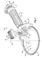
- Figure 1 is a schematic perspective view of a first exemplary embodiment of a large diameter, power operated rotary knife of the present disclosure
- Figure 2 is a schematic top plan view of the power operated knife of Figure 1 ;
- Figure 3 is a schematic exploded perspective view of the power operated rotary knife of Figure 1 ;
- Figure 4 is a schematic perspective view of an annular rotary knife blade of the power operated rotary knife of Figure 1 ;
- Figure 5 is a schematic front plan view of the annular rotary knife blade of Figure 4 ;
- Figure 6 is a schematic rear perspective view of a blade housing of the power operated rotary knife of Figure 1 ;
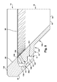
- Figure 7 is a schematic sectional view of the rotary knife blade and the mating blade housing of the power operated rotary knife of Figure 1 as seen from a plane indicated by the line 7-7 in Figure 2 , in a region of a bearing projection of the blade housing;
- Figure 8 is a schematic sectional view of the rotary knife blade and the mating blade housing of the power operated rotary knife of Figure 1 as seen from a plane indicated by the line 8-8 in Figure 2 , in a region of a fat receiving recess of the blade housing;
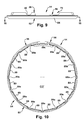
- Figure 9 is a schematic front perspective view of the blade housing of Figure 6 ;
- Figure 10 is a schematic sectional view of the rotary knife housing of Figures 6 and 9 as seen from a plane indicated by the line 10-10 in Figure 9 ;
- Figure 11 is a schematic top plan view of a second exemplary embodiment of a large diameter, power operated rotary knife of the present disclosure
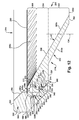
- Figure 12 is schematic sectional view of a rotary knife blade and a mating blade housing of the power operated rotary knife of Figure 11 as seen from a plane indicated by the line 12-12 in Figure 11 ;
- Figure 13 is a schematic section view of a prior art large diameter, rotary knife blade and a mating blade housing.
- the present disclosure relates to a power operated rotary knife having a large diameter, annular rotary knife blade and interfitting or mating blade housing wherein the rotary knife blade includes a notched bearing race providing for an enhanced or enlarged area of bearing contact between the blade bearing race and the corresponding blade housing bearing structure and wherein the enhanced area of bearing contact is offset radially inwardly of and axially from a radial outer surface of a drive gear region of the blade thereby reducing wear on the radial outer surface of the blade drive gear region.
- a large diameter knife blade or a large diameter power operated rotary knife shall refer to a power operated rotary knife including an annular rotary blade having an outer diameter of approximately 5 inches or greater.
- Such rotary knife blades are particularly prone to the problems of vibration and outer diameter wear discussed above.
- Such problems are mitigated by the blade and blade housing designs of the present disclosure.
- Such large diameter, power operated rotary knifes are especially suitable for trimming and cutting operations wherein a wide cut or trim layer is desired, for example, trimming wide layers skin or fat from a larger, generally flat piece of meat.
- the power operated rotary knife 10 includes a handle assembly 12, a generally annular split blade housing 14 supported by the handle assembly 12 and an annular rotary knife blade 16 supported by the blade housing 14 for rotation about a central axis of rotation CA ( Figures 1 & 2 ).
- the central axis of rotation CA of the blade 16 when the blade is mounted in the blade housing 14 for rotation therein, is substantially congruent with a central axis of the blade housing 14.
- axial, longitudinal, upper and lower shall mean movement or a dimension in a direction along or parallel to an extent of the central axis CA.
- Rotation of the rotary blade 16 is provided by a drive mechanism which includes a remote electric motor and a flexible drive shaft (not shown) which operate to rotate a drive or pinion gear 20 supported for rotation within the handle assembly 12.
- a drive mechanism which includes a remote electric motor and a flexible drive shaft (not shown) which operate to rotate a drive or pinion gear 20 supported for rotation within the handle assembly 12.
- a drive or pinion gear 20 supported for rotation within the handle assembly 12.
- other means may be employed to drive the pinion gear 20.
- an air motor or electric motor may be mounted in the handle assembly to drive the pinion gear 20.
- the handle assembly 12 includes a handle supporting, longitudinal frame member 22 and a head member 24 affixed to and extending from the frame member 22.
- the blade housing 14 is releasably mounted to the head member 24 via a clamping assembly 26.
- the frame member 22 extends away from the blade 16 along a handle axis HA ( Figure 1 ) that is substantially orthogonal to the blade central axis CA allowing an operator of the knife 10 to wield the knife with one hand.
- the frame member 22 supports a hand grip 27 that provides a gripping surface for the operator.
- the frame member 22 is adapted to receive various size and style hand grips to permit individual operators to select a hand grip which is most comfortable for the specific trimming/cutting application to be performed and the operator's hand size.
- a connector 28 screws into a threaded rear end portion of the frame member 22 to secure the hand grip 27 on the frame member.
- the connector 28 additionally includes a movable fastener 28a that secures a drive end portion of the flexible drive shaft within the frame member 22 to drive the pinion gear 20.
- the frame member 22 rigidly supports the head member 24, the pinion gear 20 and a pinion gear bearing 30 while providing a channel 32 through which the flexible drive shaft extends to make a driving connection with the pinion gear 20.
- a head assembly 34 includes the head member 24 and the clamping assembly 26 which coact to detachably affix a mounting section 36 of the blade housing 14 to the head member 24.
- the head assembly 34 additionally includes a lubrication system 38 that includes a supply of edible lubricant that is applied to the pinion gear 20 via a port 40 in the head member 24 when the operator depresses a bladder 42 of the lubrication system 38.
- the head member 24 positions the blade housing 14 relative to the handle assembly 12.
- the head member 24 is a generally crescent shaped body that defines an arcuate blade housing seating region 44, a clamp assembly receiving, socket-like cavity 46 and a boss 48 that surrounds the frame member 22 and projects from the head member opposite to the cavity 46 and seating region 44.
- the pinion gear bearing 30 is a tubular member that is fixed in the channel 32 of the frame member 22 and surrounds a shank 50 of the pinion gear 20.
- the clamping assembly 26 includes a steeling mechanism 52 by which a cutting edge 54 of the blade 16 can be straightened during operation of the knife 10.
- the handle frame member 22 may be fabricated of plastic or aluminum
- the head member 24 may be fabricated of an aluminum casting
- the clamp body 62 may be fabricated of stainless steel
- the blade 16 and blade housing 16 may be fabricated of a hardenable grade of alloy steel or a hardenable grade of stainless steel.
- the mounting section 36 of the blade housing 14 includes an angled split 56 defined between end portions 58, 60.
- the split 56 of the blade housing 14, together with the configuration of the head member 24 and the clamping assembly 26 advantageously provide for the blade 16 being removed from the blade housing without the necessity of removing the blade housing 14 from the head member 24.
- the clamp assembly 26 firmly maintains the blade housing mounting portion 36 seated against the seating region 44 of the head member 24 to rigidly position the blade 16 within the blade housing 14 while covering the pinion gear 20 which would otherwise be exposed to meat, fat, bone chips, etc. during use of the knife 10.
- the clamp assembly 26 comprises a clamp body 62 and clamping screws 64, 65.
- the clamp body 62 defines a semicircular recess confronting the head member 24 for receiving a gear portion 66 of the pinion gear 20.
- the gear portion 66 of the pinion gear 30 defines a plurality of peripherally or radially spaced apart gear teeth 66a which interfit and mesh with a plurality of peripherally spaced apart gear teeth 68a of a drive gear section 68 of the blade 16 to rotate the blade 16 within the blade housing 14.
- the clamping screws 64, 65 extend through respective holes 64a, 65a in the rear side of the head member 24 and into respective tapped holes in the clamp body 62.
- the clamping screws 64, 65 are tightened to clamp the clamp body 62 against the blade housing mounting section 36.
- the mounting section 36 includes a generally semicircular recess 70 that provides clearance for the gear portion 66 of the pinion gear 20 and a reduced height region 72 adjacent to the semicircular recess 70.
- the split 56 is radially offset from the semicircular recess 70.
- the end portions 58, 60 adjacent the angled split 56 are within the reduced height region 72 of the mounting section 36.
- This is part of an expansion structure 74 that enables the blade housing 14 to be resiliently expanded, while still connected to the head member 24 to allow removal and replacement of the rotary knife blade 16.
- the expansion structure 74 further includes pair of radially spaced apart slots 76, 78 in an outer peripheral surface of the mounting section 36.
- a boss of the clamp body 62 extends through an arcuate notch 80 in the mounting section 36.
- the notch 80 closely conforms to the shape of the clamp body boss such that when the clamping screw 64 is threaded into its respective clamp body threaded opening, the clamp body boss extends through the notch 80 and prevents the end portion 58 of the blade housing 14 from moving with respect to the clamp body 62 or the head member 24.
- the clamping screw 65 is threaded into its respective clamp body threaded opening, the end portion 60 is also prevented from moving with respect to the clamp body 62 or the head member 24.
- the clamping screw 65 When it is desired to change the blade 16, the clamping screw 65 is partially, but not completely, loosened, thus maintaining some tension in the clamping screw 65 and, therefore, some clamping force applied to the blade housing 14.
- a screwdriver, or equivalent tool is inserted in the slot 76 and levered against the head member 24 to resiliently expand the blade housing diameter.
- the screwdriver is then removed from the slot 76 and inserted into the slot 78 and levered against the head member 24 to further resiliently expand the blade housing diameter. Since the end portion 60 is in the reduced height section 72 of the mounting section 36, the end portion 60 is able to move peripherally away from the stationary end portion 58.
- the blade housing 14 further includes a blade support section 82 that extends from the mounting section 36 and forms an annular ring for supporting the blade 16.
- the blade support section 82 includes an outer wall 84 and a radially spaced apart inner wall 86.
- the inner wall 86 defines a radially extending annular opening 87 which receives the blade 16 for rotation and defines a rotational plane RP of the knife blade, the rotational plane RP being substantially orthogonal to the central axis CA of the blade.
- the inner wall 86 of the blade support section also defines an axially extending central opening CO' such that material that is cut by the cutting edge 54 of the blade 16 flows in an upward direction U ( Figure 5 ) upwardly through a central opening CO of the blade and also through the central opening CO' of the blade housing where it exits the rotary knife 10.
- the blade 16 is supported for rotation by a bearing structure 88 of the blade housing blade support section 82.
- the bearing structure 88 is defined by a portion of the inner wall 86 defining the annular opening 87.
- the blade support structure annular opening 87 and the bearing structure 88 extend around the entirety of the blade housing 14, including extending through the mounting section 36.
- the bearing structure 88 includes a plurality of spaced apart bearing projections 89.
- radially recessed regions 89a Disposed between each of the spaced apart bearing projections 89 are radially recessed regions 89a (best seen in Figures 3 , 6 & 10 ) which facilitate the draining/exiting of pieces of fat, pieces of meat and/or bone, and/or other cutting debris which may become trapped and build up in the annular opening 87 during operation of the knife 10.
- the bearing structure 88 includes fifteen bearing projections 89 and fifteen recesses 89a. It has been found that this specific combination and spacing of bearing projections 89 and recessed drain/exit regions 89a is most suitable for blade 16 stability and reduced vibration within the blade housing 16 and for facilitating the draining/exiting of cutting debris from the annular opening 87.
- the fifteen recesses 89 each subtend an angle of approximately 11°, while fourteen of the fifteen bearing projections 89 subtend an angle of approximately 11.5°.
- the fifteenth bearing projection which bridges the blade housing split 56 and is labeled 89c in Figure 10 , is radially larger than the remaining fourteen bearing projections and subtends an angle of approximately 34°. It has also been found that having a bearing projection 89 bridging the recess 56 of the blade housing 14 is advantageous in terms of blade stability and reduced vibration of the blade 16 within the blade housing 14.
- the rotary knife blade 16 includes an upper surface or upper axial end 90 and an axially spaced apart a lower surface or lower axial end 92 with a rotatable annular body 94 disposed therebetween.
- a central axis of the rotatable annular body 94 is congruent with and the same as the blade central axis CA and, for simplicity, both the blade central axis and the annular body central axis shall be referenced herein as CA.
- the upper axial end 90 includes an upper surface of the plurality of gear teeth 68a, while the lower axial end 92 includes a lower surface of the cutting edge 54 of the blade.
- the upper axial end 90 defines a generally planar surface UAEP ( Figure 5 ) and the lower axial end defines a generally planar surface LAEP.
- the planes UAEP, LAEP are substantially parallel, substantially orthogonal to the blade/annular body central axis CA, and substantially parallel to the rotation plane RP of the blade 16.
- the rotatable annular body 94 is disposed about the central axis CA and is bounded by the upper axial end 90, the lower axial end 92, an inner wall 98, and a radially spaced apart outer wall 100.
- the inner wall 98 of the blade 16 defines the central opening CO of the blade and is angled such that material that is cut by the cutting edge 54 of the blade flows upwardly through and exits the blade.
- the diameter of the central opening CO at the lower axial end 92 of the blade 16 is approximately 4.4 inches, while the outer diameter of the blade at its largest diameter, which is near the upper axial end 90 is approximately 5 inches.
- an axial height of the blade 16 measured from the upper axial end 90 to the lower axial end 92 is approximately 0.28 inches.
- the blade annular body 94 includes: a) the annular drive gear section 68 adjacent the upper axial end 90 which is adapted to be rotatably driven by the pinion gear 20; b) an annular blade section 102 adjacent the lower axial end 92; and c) an annular middle bearing race section 104 extending axially therebetween.
- the drive gear section 68 of the blade annular body 94 includes the plurality of spaced apart gear teeth 68a which extend downwardly from the upper axial end 90 and further extend between and through the outer wall 100 and the inner wall 98.
- a first portion 106 of the outer wall 100 corresponding to the drive gear section 68 of the blade 16 is generally cylindrical.
- the cylindrical first portion 106 comprises the radial outer surface of a drive gear section or region 68 and also defines the outermost radial surface of the blade 16 and the blade outer wall 100.
- a short, angled chamfer 108 Disposed axially above the outer wall cylindrical first portion 106 is a short, angled chamfer 108 that is provided for clearance purposes.
- a short, angled frustoconical portion 110 Disposed below the cylindrical first portion 106 is a short, angled frustoconical portion 110 that transitions to the middle section 104. That is, in axial position, the lower, angled portion 110 corresponds to a very bottom portion 68b of the plurality of gear teeth 68a of the drive gear section 68. However, in terms of the blade outer wall 100, the lower angled portion 110 is more easily understood to be a transition that continues into the middle section 104.
- the annular drive gear section 68 adjacent the upper axial end 90 defines two bearing surfaces: 1) a generally vertical bearing surface 106a, defined by a radial outer surface of the plurality of gear teeth 68a and corresponding to the cylindrical first portion 106; and 2) a generally horizontal bearing surface 90a, defined by an upper surface of the plurality of gear teeth 68a and corresponding to the upper axial end 90.
- the middle section 104 of the blade annular body 94 defines a bearing structure or race 112 in a second portion 114 of the outer wall 100.
- the outer wall second portion 114 is generally frustoconical, converging, that is, having a reducing diameter, in a direction proceeding toward the lower axial end 92.
- the bearing structure or race 112 includes three bearing surfaces or faces 116, 118, 120.
- the bearing race 112 includes a notch 122 extending radially inwardly from the outer wall frustoconical second portion 114 of the outer wall 100.
- the notch 122 defines the first and second bearing surfaces 116, 118.
- the third bearing surface 120 is defined by a region of the frustoconical second portion 114 of the outer wall 100 generally adjacent and spaced axially below the notch 122.
- the first bearing surface 116 is substantially parallel to the plane UAEP defined by the upper axial end 90 of the blade 16 and is substantially orthogonal to the annular body/ blade central axis CA.
- the second bearing surface 118 substantially orthogonal to the first bearing surface 116 and is substantially parallel to the annular body central axis CA.
- the third bearing surface 120 is transverse to the first and second bearing surfaces 116, 118 and is transverse to the blade central axis. Note that between the first and second bearing surfaces 116, 118, there is a small semicircular recess 117 that is provided for clearance purposes.
- a bearing structure 113 of the blade 16 includes the vertical bearing surface 106a and the horizontal bearing surface 90a of the annular drive gear section 68 and the first, second and third bearing surfaces 116, 118, 120 of the annular middle bearing race section 104 of the blade.
- the annular blade section 102 of the blade annular body 94 extends downwardly and radially inwardly from the middle bearing race section 104.
- a transition region 124 of the outer wall 100 corresponding to the transition between a lower portion 126 of the middle bearing race section 104 and an upper portion 128 of blade section 102 is stepped radially inwardly from the middle bearing race section 104 to the blade section 102.
- the blade section 102 is generally frustoconical, converging in a direction proceeding toward the lower axial end 92.
- the blade section outer wall 103a ( Figure 7 ) and the blade section inner wall 103b are both generally frustoconical and are substantially parallel.
- the blade section defines the cutting edge 54 of the blade 16 in a region of the lower axial end 92.
- the blade housing blade support section 82 supports the blade 16 for rotation in the annular opening 88 defined in the inner wall 86 of the blade housing.
- the blade housing 14 includes an upper axial end 130 and a lower axial end 132.
- the upper axial end 130 is generally planar and substantially congruent with the plane defined by the upper axial end 90 of the blade 16.
- the annular blade section 102 of the blade 16 extends below the lower axial end 130 of the blade housing blade support section 82, as does a small, lower portion 134 of the annular middle bearing race section 104 of the blade 16.
- the blade housing 14 includes the bearing structure 88 that interfits and coacts with the bearing structure 113 of the blade 16, namely, the bearing race 112, the vertical bearing surface 106a, and the horizontal bearing surface 90a of the blade 16.
- the blade bearing structure 113 and the blade housing bearing structure 88 together form a bearing interface or configuration 123 of the rotary knife 10.
- the projections 89 of the bearing structure 88 are each defined by the inner wall 86 in the region of the annular opening 87.
- the annular opening 87 of the blade housing 16 includes a generally C-shaped annular recess 138 sized to receive the drive gear section 68 of the rotary knife blade annular body 94.
- the C-shaped annular recess 138 is defined by a generally vertical portion of the blade support section inner wall 86. This generally vertical portion of the blade support section inner wall 86 in the regions of the radially inward projections 89 comprises a generally vertical bearing surface 138b.
- the generally horizontal bearing surface 138a of the blade housing bearing structure 88 bears against the generally horizontal bearing surface 90a of the blade bearing structure 113 and the generally vertical bearing surface 138b of the blade housing bearing structure 88 bears against the generally vertical bearing surface 106a of the blade bearing structure 113.
- the blade housing annular opening 87 is further defined by the radially inward projections 89 of the bearing structure 88, the projections being disposed below the annular recess 138.
- the blade housing bearing structure 88 for each projection 89, includes a first bearing surface 140 engaging the first bearing surface 116 of the rotary knife blade bearing race 112, a second bearing surface 142 engaging the second bearing surface 118 of the rotary knife blade bearing race, and a third bearing surface 144 engaging the third bearing surface 120 of the rotary knife blade bearing surface.
- the first bearing surface 140 is generally planar in the horizontal direction and substantially parallel to the planes defined by the upper and lower axial ends 130, 132 of the blade housing blade support section 82.
- the second bearing surface 142 is generally cylindrical, orthogonal to the first bearing surface 140 and the upper and lower axial ends 130, 132 and substantially parallel to the blade housing central axis.
- the first and second bearing surfaces 140, 142 can be viewed a substantially right-angled boss 141 of the blade housing bearing structure 88 that projects radially inwardly into and bears against the first and second bearing surfaces 116, 118 defined by the notch 122 of the blade bearing race 112.
- the third bearing surface 144 is generally frustoconical, converging in a direction proceeding toward the lower axial end 132 of the blade housing blade support section 82. Note that between the second and third bearing surfaces 142, 144 there is a small semicircular recess 143 that is provided for clearance purposes.
- the outer wall 84 of the blade housing blade support section 82 includes an upper, generally cylindrical section 146 and a lower, frustoconical section 148, converging in a direction proceeding toward the lower axial end 132 of the blade housing blade support section 82.
- a lower portion 150 of the upper cylindrical section 146 terminates approximately in horizontal alignment with the upper axial end 90 of the blade 16.
- an upper portion 152 of the blade housing blade support section 82 is thick and blocky to provide the strength and rigidity necessary to absorb the substantial torque applied to the blade housing 14 by the operator when, for example, applying significant force to the handle grip 27 when using a distal or forwardmost end F ( Figure 2 ) of the knife 10 to cut a thick, dense piece of meat or cutting against a bone.
- the lower frustoconical section 148 is sharply raked or angled to provide clearance and minimize friction between the blade housing outer wall 84 and the remainder of the piece of meat that the trimming or cutting is being done with respect to.
- FIG. 7 a sectional view of the blade 16 and blade housing is schematically shown in a region where a bearing projection 89 is present.
- Figure 8 a sectional view of the blade 16 and blade housing 14 is schematically shown in a region where a recessed drain/exit region 89a is present.
- the right-angled boss 141 of the projection 89 of blade housing bearing structure 88 is not present in the the recessed region 89a. Instead, the angled boss 141 is replaced by a flat, frustoconical portion 145 that defines a lower portion of the blade housing inner wall 86.
- a gap G exists between the blade housing inner wall 86 and the outer wall 100 of the blade 16 to facilitate for draining of fat, meat and other debris that accumulate in the annular opening 87 during operation of the knife 10.
- the gap G extends between the blade housing annular recess 130 and the blade cylindrical first section 106 in a region labeled G1.
- the generally vertical blade housing bearing surface 138b is not present. Instead, the blade support section inner wall 84 is recessed radially outwardly such that the gap G exists between the cylindrical first portion 106 of the blade 16 and inner wall 86 in the region G1.
- the gap G further extends downwardly between the frustoconical portion 145 of the blade housing inner wall 86 and the blade annular middle bearing race section 104 in a region labeled G2 to the lower axial end 132 of the blade housing 14, as explained above, due to the removal of the blade housing angled boss 141.
- the power operated rotary knife 10 of the present disclosure mitigates the problems of wearing of the blade radial outer surface 106 and resulting vibration characteristic of prior art, large diameter blades.
- the middle bearing race section 104 of the annular body 94 of the blade 16 enlarges or enhances the area of bearing interface between the blade bearing structure 113 and the blade housing bearing structure 88 resulting in an improved bearing configuration 123 for the rotary knife.
- the middle bearing race section 104 includes the notch 122 that provides for an enhanced or enlarged area of bearing contact between the blade bearing race 112 and the corresponding blade housing bearing structure 88.
- the bearing surfaces 116, 118, 120 when viewed in cross section as seen in Figure 7 , have respective lengths of approximately 0.022 inches, 0.020 inches and 0.040 inches, for a total effective bearing surface length of approximately 0.082 inches.
- the prior art blade 500 which is similar in outer diameter, inner diameter and axial height to the blade 16, when viewed in cross section as seen in Figure 13 , for the frustoconical bearing surface 512, has an effective bearing surface length of 0.076 inches.
- the effective bearing length of the blade bearing race 112 of the blade 16 of the present disclosure is 0.006 inch greater, in percentage terms, an increase of 7.9%.
- the bearing surfaces 116, 118, 120 are solid, that is, they are not weakened or reduced by gaps between the plurality of gear teeth as is the case with, for example, the vertical blade bearing surface 508 of the prior art blade design 500.
- the increased bearing area afforded by the blade bearing race 112 of the blade 16 reduces the rate of wear experienced by the vertical bearing surface 106a of the drive gear section 68 of the blade 16.
- the vertical bearing surface 118 of the bearing race 112 and the vertical bearing surface 106a of the drive gear section 68 share or split the radially outwardly directed component of loading force transmitted through the blade 16 during cutting or trimming operations.
- the vertical bearing surface 118 accepts and bears a portion of the force that would be otherwise be absorbed by the gear vertical bearing surface 106a and since, unlike gear vertical bearing surface 106a, the vertical bearing surface 118 of the bearing race 112 is solid, the rate of wear experienced by the gear vertical bearing surface 106a is reduced. This advantageously provides for less vibration during use of the knife 10 and mitigates the need for or prolongs the time until the operator is required to change the diameter of the blade housing 14 during use of the knife 10.
- the enhanced area of bearing contact afforded by the notched bearing race 112 is offset radially inwardly of and axially from the radial outer surface 106 of the drive gear region 68 of the blade 16 thereby reducing wear on the radial outer surface of the blade drive gear region.
- the blade 16, the blade housing 14, the blade bearing race 112, and the blade housing bearing structure 88 of the present disclosure advantageously provide for less vibration during use and mitigate the need for or prolong the time until the operator is required to change the diameter of the blade housing 14 during use of the knife 10.
- a second exemplary embodiment of a power operated rotary knife of the present disclosure is shown generally at 200 in Figure 11 .
- the rotary knife 200 of the second embodiment is similar in overall configuration to the rotary knife 10 of the first embodiment and includes a rotary knife blade 216 supported for rotation within a blade housing 214.
- the blade housing 214 includes a mounting section 236 and a blade support section 282, similar to the first embodiment.
- Figure 9 schematically illustrates a sectional view of the bearing interface of the rotary knife blade 216 and the blade support section 282 of the blade housing 214.
- the blade is more sharply raked than the blade 16 of the first embodiment, that is, if an angle ⁇ is drawn between an axis CA' which is parallel to the central axis of rotation CA of the blade 216 and an inner wall 298, the angle ⁇ would be greater than a corresponding angle ⁇ between the central axis CA and the inner wall 98 of the first embodiment rotary knife blade 16.
- an outer diameter of the blade 216 is approximately the same as the outer diameter of the first embodiment blade 16, namely, about 5 inches.
- an inner diameter of the blade 216 at a lower axial end 292 of the blade is approximately 4 inches, compared to a larger inner diameter of the first embodiment blade 16 at the lower axial end 92 of approximately 4.4 inches.
- the axial height of the blade 216 of the present embodiment from upper axial end 290 to lower axial end 292 is approximately 0.28 inches.
- annular, frustoconical surface second portion 114 of the outer wall 100 was substantially parallel to the frustoconical outer wall 103a of the annular blade section 102 and to the frustoconical inner wall 103b of the blade section 102.
- annular, frustoconical surface second portion 314 of an outer wall 300 is not parallel to a frustoconical outer wall 303a of an annular blade section 302 nor is the frustoconical outer wall 303a parallel to a frustoconical inner wall 303b of the blade section 302.
- the rotary knife blade 216 includes the upper surface or upper axial end 290 and the axially spaced apart a lower surface or lower axial end 292 with a rotatable annular body 294 disposed therebetween.
- a central axis of the rotatable annular body 294 is congruent with and the same as the blade central axis CA.
- the upper axial end 290 includes an upper surface of a plurality of gear teeth 268a, while the lower axial end 292 includes a lower surface of a cutting edge 254 of the blade.
- the rotatable annular body 294 is disposed about the central axis CA and is bounded by the upper axial end 290, the lower axial end 292, the inner wall 298, and the radially spaced apart outer wall 300.
- the blade annular body 294 includes: a) an annular drive gear section 268 adjacent the upper axial end 290 which is adapted to be rotatably driven by the pinion gear 20; b) an annular blade section 302 adjacent the lower axial end 292; and c) an annular middle bearing race section 304 extending axially therebetween.
- the first portion 306 of the outer wall 300 corresponding to the drive gear section 268 of the blade 216 is generally cylindrical. As can be seen in Figure 9 , the first portion 306 comprises the radial outer surface of a drive gear section or region 268 and also comprises the outermost radial surface of the blade 216 and the blade outer wall 300. Disposed axially above the outer wall first portion 306 is a short, angled chamfer 308 that is provided for clearance purposes. Disposed axially below the first portion 306 is a short, frustoconical, angled lower portion 310 that transitions to the middle section 304.
- the middle section 304 of the blade annular body 294 defines a bearing race 312 in the second frustoconical portion 314 of the outer wall 300.
- the outer wall second portion 314 is generally frustoconical, converging, that is, having a reducing diameter, in a direction proceeding toward the lower axial end 292.
- the bearing race 312 includes three bearing surfaces or faces 316, 318, 320.
- the bearing race 312 includes a notch 322 extending radially inwardly from the outer wall frustoconical second portion 314 of the outer wall 300.
- the notch 322 defines the first and second bearing surfaces 316, 318.
- the third bearing surface 320 is defined by a region of the frustoconical second portion 314 of the outer wall 300 generally adjacent and spaced axially below the notch 322.
- the first bearing surface 316 is substantially parallel to a plane defined by the upper axial end 290 of the blade 216 and is substantially orthogonal to the annular body/ blade central axis CA.
- the second bearing surface 318 substantially orthogonal to the first bearing surface 316 and is substantially parallel to the annular body central axis CA.
- the third bearing surface 320 is transverse to the first and second bearing surfaces 316, 318 and is transverse to the blade central axis. Note that between the first and second bearing surfaces 316, 318, there is a small semicircular recess 317 that is provided for clearance purposes.
- a bearing structure 313 of the blade 216 includes the vertical bearing surface 306a and the horizontal bearing surface 290a of the annular drive gear section 268 and the first, second and third bearing surfaces 316, 318, 320 of the annular middle bearing race section 304 of the blade.
- the annular blade section 302 of the blade annular body 294 extends downwardly and radially inwardly from the middle bearing race section 304.
- a transition region 324 of the outer wall 300 corresponding to the transition between a lower portion of the middle bearing race section 304 and an upper portion of blade section 302 is stepped radially inwardly from the middle bearing race section 304 to the blade section 302.
- the blade section 302 is generally frustoconical, converging in a direction proceeding toward the lower axial end 292.
- the blade section outer wall 303a and the blade section inner wall 303b are both generally frustoconical.
- the blade section defines the cutting edge 254 of the blade 216 in a region of the lower axial end 292.
- the blade housing blade support section 282 supports the blade 216 for rotation in the annular opening 287 defined in the inner wall 286 of the blade housing.
- the blade housing 214 includes an upper axial end 330 and a lower axial end 332.
- the upper axial end 330 is generally planar and substantially congruent with the plane defined by the upper axial end 290 of the blade 216.
- the annular blade section 302 of the blade 216 extends below the lower axial end 330 of the blade housing blade support section 282, as does a small, lower portion 334 of the annular middle bearing race section 304 of the blade 216.
- the blade housing 214 includes the bearing structure 288 that interfits and coacts with the bearing structure 313 of the blade 216, namely, the bearing race 312, the vertical bearing surface 306a, and the horizontal bearing surface 290a of the blade 216.
- the blade bearing structure 313 and the blade housing bearing structure 288 together form a bearing interface or configuration 323 of the rotary knife 200.
- the projections 289 of the bearing structure 288 are each defined by the inner wall 286 in the region of the annular opening 287.
- the annular opening 287 of the blade housing 216 includes a generally C-shaped annular recess 338 sized to receive the drive gear section 268 of the rotary knife blade annular body 294.
- An annular, upper horizontal surface of the blade support section inner wall 286 defining an upper portion of the C-shaped annular recess 338 comprises a generally horizontal bearing surface 338a, substantially aligned with and overlying the horizontal bearing surface 290a of the blade drive gear section 268.
- the C-shaped annular recess 338 is defined by a generally vertical portion of the blade support section inner wall 286.
- This generally vertical portion of the blade support section inner wall 286 in the regions of the radially inward projections 289 comprises a generally vertical bearing surface 338b.
- the generally horizontal bearing surface 338a of the blade housing bearing structure 288 bears against the generally horizontal bearing surface 290a of the blade bearing structure 313 and the generally vertical bearing surface 338b of the blade housing bearing structure 288 bears against the generally vertical bearing surface 306a of the blade bearing structure 313.
- the bearing structure 288, for each projection 289, includes a first bearing surface 340 engaging the first bearing surface 316 of the rotary knife blade bearing race 312, a second bearing surface 342 engaging the second bearing surface 318 of the rotary knife blade bearing race, and a third bearing surface 344 engaging the third bearing surface 320 of the rotary knife blade bearing surface.
- the first bearing surface 340 is generally planar in the horizontal direction and substantially parallel to the planes defined by the upper and lower axial ends 330, 332 of the blade housing blade support section 282.
- the second bearing surface 342 is generally cylindrical, orthogonal to the first bearing surface 340 and the upper and lower axial ends 330, 332 and substantially parallel to the blade housing central axis.
- the third bearing surface 344 is generally frustoconical, converging in a direction proceeding toward the lower axial end 332 of the blade housing blade support section 282. Note that between the second and third bearing surfaces 342, 344 there is a small semicircular recess 343 that is provided for clearance purposes.
- the outer wall 284 of the blade housing blade support section 282 includes an upper, generally cylindrical section 346 and a lower, frustoconical section 348, converging in a direction proceeding toward the lower axial end 332 of the blade housing blade support section 282.
- a lower portion 350 of the upper cylindrical section 346 terminates approximately in horizontal alignment with the upper axial end 290 of the blade 216.
- an upper portion 352 of the blade housing blade support section 282 is thick and blocky to provide the strength and rigidity necessary to absorb the substantial torque applied to the blade housing 214 by the operator when, for example, applying significant force to the handle grip 227 when using a distal or forwardmost end F ( Figure 11 ) of the knife 200 to cut a thick, dense piece of meat or cutting against a bone.
- the lower frustoconical section 348 is sharply raked or angled to provide clearance and minimize friction between the blade housing outer wall 284 and the remainder of the piece of meat that the trimming or cutting is being done with respect to.
- the power operated rotary knife 200 of the present disclosure mitigates the problems of wearing of the blade radial outer surface 306 and resulting vibration characteristic of prior art, large diameter blades.
- the middle bearing race section 304 of the annular body 294 of the blade 216 functions to enlarged or enhanced the area of bearing interface between the blade bearing structure 313 and the blade housing bearing structure 288 resulting in an improved bearing configuration 323 for the rotary knife.
- the middle bearing race section 304 includes the notch 222 that provides for an enhanced or enlarged area of bearing contact between the blade bearing race 312 and the corresponding blade housing bearing structure 288.
- the bearing surfaces 316, 318, 320 are solid, that is, they are not weakened or reduced by gaps between the plurality of gear teeth as is the case with, for example, the vertical blade bearing surface 508 of the prior art blade design 500.
- the increased bearing area afforded by the blade bearing race 312 of the blade 216 reduces the rate of wear experienced by the vertical bearing surface 306a of the drive gear section 268 of the blade 216.
- the vertical bearing surface 318 of the bearing race 312 and the vertical bearing surface 306a of the drive gear section 268 share or split the radially outwardly directed component of loading force transmitted through the blade 216 during cutting or trimming operations.
- the vertical bearing surface 318 accepts and bears a portion of the force that would be otherwise be absorbed by the gear vertical bearing surface 306a and since, unlike gear vertical bearing surface 306a, the vertical bearing surface 318 of the bearing race 312 is solid, the rate of wear experienced by the gear vertical bearing surface 306a is reduced. This advantageously provides for less vibration during use of the knife 200 and mitigates the need for or prolongs the time until changing the diameter of the blade housing 214 during use of the knife 200.
- the enhanced area of bearing contact afforded by the notched bearing race 312 is offset radially inwardly of and axially from the radial outer surface 306 of the drive gear region 268 of the blade 216 thereby reducing wear on the radial outer surface of the blade drive gear region.
- the blade 216, the blade housing 214, the blade bearing structure 113, and the blade housing bearing structure 288 of the present disclosure advantageously provide for less vibration during use and mitigate the need for or prolong the time until the operator is required to change the diameter of the blade housing 214 during use of the knife 200.
- orientation such as upper, lower, inward, outward, forward, etc., are provided for convenience purposes and relate generally to the orientation shown in the Figures. Such orientation terms are not intended to limit the scope of the present disclosure or the claims appended hereto.
- a first embodiment of the present invention includes a rotary knife blade for a power operated rotary knife, the rotary knife blade comprising:
- the inner wall of the rotary knife blade may extending between the upper axial end and the lower axial end may be generally frustoconical converging in a direction proceeding toward the lower axial end.
- the angle of the portion of the frustoconical outer wall of the rotary knife bladr corresponding to the middle bearing race section with respect to the central axis may be substantially the same as an angle of the portion of the frustoconical outer wall corresponding to the blade section.
- the frustoconical inner wall of the rotary knife blade with respect to the central axis may be substantially the same as the angle of the portion of the frustoconical outer wall corresponding to the middle bearing race section with respect to the central axis.
- the angle of the frustoconical inner wall of the rotary knife blade with respect to the central axis may be substantially the same as an angle of the portion of the frustoconical outer wall corresponding to the blade section.
- the generally cylindrical surface of the outer wall portion of the rotary knife blade corresponding to the gear section may be substantially parallel to the central axis.
- the drive gear section of the rotary knife blade may define two bearing surfaces: a) a generally vertical bearing surface, defined by a radial outer surface of the plurality of gear teeth and corresponding to the cylindrical outer wall first portion; and 2) a generally horizontal bearing surface, defined by an upper surface of the plurality of gear teeth and corresponding to the upper axial end.
- a further embodiment of the present invention includes a power operated rotary knife, comprising: the rotary knife blade of any preceding claim; and a split blade housing configured to support the knife blade for rotation therein.
- the blade housing of the power operated rotary knife may include a mounting section and an annular blade support section, the mounting section being disposed between the clamping assembly and the handle assembly head member to secure the blade housing to the handle assembly, the blade support section including an outer wall and a radially spaced apart inner wall, the inner wall defining an annular recess sized to receive the drive gear section of the rotary knife blade annular body and a radially inwardly projecting bearing structure disposed below the annular recess, the bearing structure including a first bearing surface adapted to engage the first bearing surface of the rotary knife blade bearing race, a second bearing surface adapted to engage the second bearing surface of the rotary knife blade bearing race, and a third bearing surface adapted to engage the third bearing surface of the rotary knife blade bearing race.
- the power operated rotary knife may further comprise
- the bearing structure of the blade housing of the power operated rotary knife may be defined by a plurality of circumferentially spaced apart bearing projections formed in the annular blade support section.
- the mounting section of the blade housing of the power operated rotary knife may include a circularly curved wall adapted to be mounted to the power operated rotary knife and a split extends through the mounting section.
- the radially inwardly projecting bearing structure of the blade support section of the power operated rotary knife may comprise a plurality of spaced apart bearing projections radially spaced apart by recessed regions that do not contact the blade.
- the blade drive gear section of the power operated rotary knife may define two bearing surfaces: a) a generally vertical bearing surface, defined by a radial outer surface of the plurality of gear teeth and corresponding to the cylindrical outer wall first portion; and b) a generally horizontal bearing surface, defined by an upper surface of the plurality of gear teeth and corresponding to the upper axial end.
- the blade housing annular recess of the power operated rotary knife sized to receive the drive gear section of the rotary knife blade annular body may define: a) a generally horizontal bearing surface adapted to engage the generally horizontal bearing surface of the blade drive gear section; and b) a generally vertical bearing surface adapted to engage the generally vertical bearing surface of the blade drive gear section
Abstract
Description
- The present disclosure relates to a power operated rotary knife have a large diameter, annular rotary knife blade and, more specifically, to a power operated rotary knife having a large diameter, annular rotary knife blade and interfitting blade housing wherein the rotary knife blade includes a notched bearing race providing for an enhanced or enlarged area of bearing contact between the blade bearing race and the corresponding blade housing bearing structure and wherein the enhanced area of bearing contact is offset radially inwardly of and axially from a radial outer surface of a drive gear region of the blade thereby reducing wear on the radial outer surface of the blade drive gear region.
- Power operated rotary knives are widely used in meat processing facilities for meat cutting and trimming operations. Such power operated rotary knives typically include a handle assembly including a head member extending from the handle assembly, an annular blade housing coupled to the head member via a clamp assembly, and an annular rotary blade supported for rotation by the blade housing. The annular rotary blade of a conventional power operated rotary knife is rotated by a drive mechanism including a flexible drive shaft which extends through an opening in the handle assembly and engages a pinion gear supported in a distal portion of the handle assembly head member. The flexible drive shaft includes a stationary outer sheath and a rotatable interior drive shaft which is driven by a pneumatic or electric motor. Gear teeth of the pinion gear engage mating gear teeth formed on an upper surface of an annular body of the annular rotary blade. A blade section of the rotary blade extends downwardly from the annular body. Upon rotation of the pinion gear by the flexible drive shaft, the annular rotary blade rotates within the blade housing at a high RPM, on the order of 1,500 - 2,000 RPMs. Conventional power operated rotary knives are disclosed in
U.S. Pat. Nos. 6,354,949 to Baris et al. ,6,751,872 to Whited et al. ,6,769,184 to Whited , and6,978,548 to Whited et al. , all of which are assigned to the assignee of the present invention and all of which are incorporated herein in their respective entireties by reference. - Depending upon the application, power operated rotary knives are offered in various sizes. Size may be measured in terms of an outer diameter of the annular rotary blade. Typical annular rotary blade may vary in size from, for example, as 1.4 inches to over 7 inches. For a given annular blade rotational speed, e.g., 2000 RPM, it is clear that the linear velocity of an outer surface of the blade bearing against the blade housing increases with increasing blade diameter. As such, problems of wear on the blade bearing surface and vibration of the blade as it rotates within the blade housing are accentuated in power operated rotary knives with large blade diameters. As used herein, rotary knife blades with outer diameters of approximately 5 inches or greater are considered large diameter blades, such blades being particularly prone to the problems discussed herein.
- The blade housings of large diameter rotary knives typically include a split blade housing for blade replacement while the blade housing remains attached to the handle assembly head member. The clamping assembly is loosened on one side of the split of the split blade housing thereby allowing one end of the blade housing adjacent the split to be moved away from the other end of the blade housing. Relative movement of the one end of the blade housing away from the other end expands the blade housing diameter and allows removal of a blade and insertion of a new blade, while the other end of the blade housing remains attached to the head member. Upon insertion of a new blade, the blade housing is returned to its unexpanded state and the loosened side of the clamping assembly is tightened to secure the blade housing in place.
- Unfortunately, properly returning and securing the blade housing to its unexpanded state tends to be a trial and error procedure, especially for new, untrained operators of a power operated rotary knife. If the blade housing diameter is returned to a diameter that is too small for the blade, the blade will tend to stick or potentially lock up in the blade housing. If the blade housing diameter is returned to a diameter that is too large for the blade, the blade will not be properly supported in the blade housing and will tend to vibrate.
- A problem with larger diameter blades involves wear on the radial outermost surface of the blade. In conventional large diameter power operated rotary knives, the radially outermost surface of the blade corresponding to the drive gear region of the blade, that is, the upper region of the blade where the plurality of gear teeth are formed, functions as a bearing surface. As such, the blade housing contacts and bears against the radial outer surface of the drive gear region of the blade. This causes the radially outer surface of the blade drive gear region to wear down as the blade rotates in the blade housing, thereby reducing the effective outer diameter of the blade.
- Reducing the outer diameter of the blade in the blade drive gear region causes problems in terms of increased vibration. That is, as the blade outer diameter decreases, the blade becomes looser within the blade housing and hence is prone to vibration within the housing at high rotational speeds. Increased vibration makes the knife more difficult to operate and increases operator fatigue. The operator will either look for another knife or be forced to attempt to adjust the diameter of the blade housing to a smaller diameter to match the decreased blade diameter. Such adjustments or attempted adjustments of the blade housing diameter on the part of the operator decrease operator productivity and increase operator dissatisfaction with the knife, both of which are undesirable results.
- In
Figure 13 , a section view of a portion of a prior art large diameter power operated rotary knife is shown. Theprior art blade 500 andblade housing 502 are shown to schematically illustrate the blade - blade housing bearingstructure 504. The priorart bearing structure 504 includes a first,cylindrical bearing surface 506 of theblade housing 502, which bears against a mating cylindrical bearingsurface 508 of theblade 500, a second, frustoconical bearingsurface 510 of theblade housing 502 which bears against a mating frustoconical bearingsurface 512 of theblade 500, and a third, horizontally orientedannular bearing surface 514 of theblade housing 502 which bears against a mating horizontal,annular bearing surface 516 of theblade 500. As can be seen, the firstcylindrical bearing surface 508 of theblade 500 includes a radial outer surface of adrive gear section 518 of the blade and the third horizontalannular bearing surface 516 of the blade includes an upper surface of the drive gear section of the blade. - Not all of the mating bearing surfaces of the blade - blade housing are in contact at any given time because there are necessarily running clearances between the
blade 500 and theblade housing 502 which allow the blade to rotate relatively freely within the blade housing. These running clearances cause theblade 500 to act somewhat akin to a teeter-totter within theblade housing 502, that is, as one region of the blade is pivoted or moved upwardly within the blade housing during a cutting or trimming operation, the diametrically opposite portion of the blade (180° away) is pivoted or moved downwardly within the blade housing. Accordingly, the mating bearing surfaces in contact at a specific location of the blade - blade housing interface will change and, at any given time, will be determined by the forces applied during use of the rotary knife. - For example, if, when viewed from the perspective of the operator, the right side of the
blade 500 is being used for cutting or trimming meat, i.e., the region labeled T inFigure 2 , theblade edge 520 in the region T (the loaded side of the blade) will transmit a force vector along the blade generally in the direction labeled F inFigure 13 . This will cause the mating blade housing - blade bearingsurfaces surfaces blade 500 within theblade housing 502, i.e., the blade housing bearingsurfaces blade 500, the region labeled O inFigure 2 , that is, the unloaded side of the blade, will experience a force vector in a direction F' which is generally perpendicular to the direction F shown inFigure 13 , that is, bearing against the bladehousing bearing surface 510. Theblade 500 will tend to move generally downwardly and radially inwardly within theblade housing 502, thus, the blade housing - blade bearingsurfaces surfaces - A problem with the prior art bearing structure shown in
Figure 13 is that the cylindricalblade bearing surface 508 is comprised of a plurality of gear teeth, that is, theradial surface 508 has gaps between each pair of adjacent gear teeth, for example,adjacent gear teeth gap 526 between them. Because of the gaps in the cylindricalblade bearing surface 508 and the small axial height of that surface on the order of 0.034 inch, the area of thebearing surface 508 is small. Given the large loading forces applied to thecylindrical surface 508 during cutting and trimming operations, in the prior art design, the radial outer surface of theprior art blade 500 will wear rapidly during use. - As the radial
outer surface 508 is the largest outer diameter of theblade 500, the result of such wear of the radialouter surface 508 is that theblade 500 outer diameter will decrease and the blade will tend to vibrate in theblade housing 502. As the radialouter surface 508 wears, theblade 500 becomes looser and looser within theblade housing 502. Increasing vibration will result in greater operator fatigue and lower productivity. An inexperienced operator may simply accept the increased vibration as a necessary part of using a power operated knife and reduce productivity by cutting slower, turning the knife off, taking additional time between cuts, etc. - An experienced operator may recognize that a potential solution to the problem of increased vibration is to adjust, that is, reduce the blade housing diameter to account for the decreased outer diameter of the blade. As described above, adjustment of the blade housing diameter involves loosening the
clamping screw 65, using a screwdriver or other tool to leverage theslot 76 against thehead member 24 to adjust blade housing diameter, and then tightening the clamping screw. There are numerous problems with this approach. First, it is a trial and error technique that requires the operator to find a suitable blade housing diameter. For example, if the blade housing diameter is made too small, the blade may lock up in the housing. Second, even if the operator is successful in adjusting the blade housing to an acceptable diameter, valuable working time has been lost in the adjustment process. Finally, since wear of the radialouter surface 508 of theblade 500 is ongoing, the adjustment is only a temporary fix as further wear occurs. - What is needed is a blade - blade housing bearing structure for large diameter power operated rotary knives that results in less wear in the radial outermost surface of the blade, that is, less wear in the radial outer surface of the blade drive gear region. What is also needed is a blade - blade housing bearing structure for large diameter power operated rotary knives that results in less vibration of the knife as the knife is used. What is also needed is a blade - blade housing bearing structure that is less sensitive to blade housing diameter adjustment errors and/or requires less blade housing diameter adjustments.
- In one aspect, the present disclosure relates to a rotary knife blade for a power operated rotary knife including a rotatable annular body disposed about a central axis and bounded by an upper axial end, an axially spaced apart lower axial end, an inner wall, and a radially spaced apart outer wall, the annular body including an annular drive gear section adjacent the upper axial end adapted to be rotatably driven by a pinion gear, an annular blade section adjacent the lower axial end, and an annular middle bearing race section extending axially therebetween; the drive gear section comprising a plurality of spaced apart gear teeth extending downwardly from the upper axial end and extending between and through the outer wall and the inner wall, a first portion of the outer wall corresponding to the drive gear section being generally cylindrical; the middle section defining a bearing race in a second portion of the outer wall corresponding to the middle section, the outer wall second portion being generally frustoconical, converging in a direction proceeding toward the lower axial end, the bearing race comprising a notch extending radially inwardly from the outer wall frustoconical second portion defining first and second bearing surfaces and a region of the outer wall frustoconical second portion adjacent and below the notch defining a third bearing surface, the first bearing surface substantially parallel to a plane defined by the upper axial end and orthogonal to the annular body central axis, the second bearing surface substantially orthogonal to the first bearing surface and parallel to the annular body central axis, and the third bearing surface transverse to the first and second bearing surfaces and the annular body central axis; and the blade section extending downwardly and radially inwardly from the middle section, a portion of the outer wall corresponding to the blade section being stepped radially inwardly from the portion of the outer wall corresponding to the middle section and being generally frustoconical, converging in a direction proceeding toward the lower axial end, the blade section defining a cutting edge at the lower axial end.
- In one exemplary embodiment, the inner wall extending between the upper axial end and the lower axial end is generally frustoconical converging in a direction proceeding toward the lower axial end. In another exemplary embodiment, an angle of the portion of the frustoconical outer wall corresponding to the middle bearing race section with respect to the central axis is substantially the same as an angle of the portion of the frustoconical outer wall corresponding to the blade section. In another exemplary embodiment, an angle of the frustoconical inner wall with respect to the central axis is substantially the same as the angle of the portion of the frustoconical outer wall corresponding to the middle bearing race section with respect to the central axis. In another exemplary embodiment, an angle of the frustoconical inner wall with respect to the central axis is substantially the same as an angle of the portion of the frustoconical outer wall corresponding to the blade section. In another exemplary embodiment, the generally cylindrical surface of the outer wall portion corresponding to the gear section is substantially parallel to the central axis.
- In another aspect, the present disclosure relates to a combination of a rotary knife blade and blade housing for a power operated rotary knife, the combination comprising an annular knife blade and a split blade housing configured to support the annular knife blade for rotation therein, the annular knife blade including a rotatable annular body disposed about a central axis and bounded by an upper axial end, an axially spaced apart lower axial end, an inner wall, and a radially spaced apart outer wall, the annular body including an annular drive gear section adjacent the upper axial end adapted to be rotatably driven by a pinion gear, an annular blade section adjacent the lower axial end, and an annular middle bearing race section extending axially therebetween; the drive gear section comprising a plurality of spaced apart gear teeth extending downwardly from the upper axial end and extending between and through the outer wall and the inner wall, a portion of the outer wall corresponding to the drive gear section being generally cylindrical; the middle section comprising a bearing race extending radially inwardly in a portion of the outer wall in the middle section, the bearing race defined by a first bearing surface substantially parallel to a plane defined by the upper axial end and orthogonal to the annular body central axis and a second bearing surface substantially orthogonal to the first bearing surface and parallel to the annular body central axis, the portion of the outer wall corresponding to the middle section being generally frustoconical, converging in a direction proceeding toward the lower axial end; and the blade section extending downwardly and radially inwardly from the middle section, a portion of the outer wall corresponding to the blade section being stepped radially inwardly from the portion of the outer wall corresponding to the middle section and being generally frustoconical, converging in a direction proceeding toward the lower axial end, the blade section defining a cutting edge at the lower axial end; the blade housing including a mounting section and an annular blade support section, the blade support section including an outer wall and a radially spaced apart inner wall, the inner wall defining an annular recess sized to receive the drive gear section of the rotary knife blade annular body and a radially inwardly projecting bearing structure disposed below the annular recess, the bearing structure including a first bearing surface engaging the first bearing surface of the rotary knife blade bearing race, a second bearing surface engaging the second bearing surface of the rotary knife blade bearing race, and a third bearing surface engaging the third bearing surface of the rotary knife blade bearing surface.
- In one exemplary embodiment, the inner wall of the rotary knife blade extending between the upper axial end and the lower axial end is generally frustoconical converging in a direction proceeding toward the lower axial end. In another exemplary embodiment, an angle of the portion of the frustoconical outer wall of the rotary knife blade corresponding to the middle bearing race section with respect to the central axis is substantially the same as an angle of the portion of the frustoconical outer wall corresponding to the blade section. In another exemplary embodiment, an angle of the frustoconical inner wall of the rotary knife blade with respect to the central axis is substantially the same as the angle of the portion of the frustoconical outer wall corresponding to the middle bearing race section with respect to the central axis. In another exemplary embodiment, an angle of the frustoconical inner wall of the rotary knife blade with respect to the central axis is substantially the same as an angle of the portion of the frustoconical outer wall corresponding to the blade section. In another exemplary embodiment, the generally cylindrical surface of the outer wall portion corresponding to the gear section of the rotary knife blade is substantially parallel to the central axis. In another exemplary embodiment, the bearing structure of the blade housing is defined by a plurality of circumferentially spaced apart bearing projections formed in the annular blade support section. In another exemplary embodiment, the mounting section of the blade housing includes a circularly curved wall adapted to be mounted to the power operated rotary knife and a split extends centrally through the mounting section.
- In another aspect, the present disclosure relates to a power operated rotary knife comprising an annular knife blade; a split blade housing configured to support the annular knife blade for rotation therein; a handle assembly including a head member; and a clamping assembly for securing the blade housing to the handle assembly head member; the annular knife blade including a rotatable annular body disposed about a central axis and bounded by an upper axial end, an axially spaced apart lower axial end, an inner wall, and a radially spaced apart outer wall, the annular body including an annular drive gear section adjacent the upper axial end adapted to be rotatably driven by a pinion gear, an annular blade section adjacent the lower axial end, and an annular middle bearing race section extending axially therebetween; the drive gear section comprising a plurality of spaced apart gear teeth extending downwardly from the upper axial end and extending between and through the outer wall and the inner wall, a portion of the outer wall corresponding to the drive gear section being generally cylindrical; the middle section comprising a bearing race extending radially inwardly in a portion of the outer wall in the middle section, the bearing race defined by a first bearing surface substantially parallel to a plane defined by the upper axial end and orthogonal to the annular body central axis and a second bearing surface substantially orthogonal to the first bearing surface and parallel to the annular body central axis, the portion of the outer wall corresponding to the middle section being generally frustoconical, converging in a direction proceeding toward the lower axial end; and the blade section extending downwardly and radially inwardly from the middle section, a portion of the outer wall corresponding to the blade section being stepped radially inwardly from the portion of the outer wall corresponding to the middle section and being generally frustoconical, converging in a direction proceeding toward the lower axial end, the blade section defining a cutting edge at the lower axial end; the blade housing including a mounting section and an annular blade support section, the mounting section being disposed between the clamping assembly and the handle assembly head member to secure the blade housing to the handle assembly, the blade support section including an outer wall and a radially spaced apart inner wall, the inner wall defining an annular recess sized to receive the drive gear section of the rotary knife blade annular body and a radially inwardly projecting bearing structure disposed below the annular recess, the bearing structure including a first bearing surface engaging the first bearing surface of the rotary knife blade bearing race, a second bearing surface engaging the second bearing surface of the rotary knife blade bearing race, and a third bearing surface engaging the third bearing surface of the rotary knife blade bearing surface.
- In one exemplary embodiment, the inner wall of the rotary knife blade extending between the upper axial end and the lower axial end is generally frustoconical converging in a direction proceeding toward the lower axial end. In another exemplary embodiment, an angle of the portion of the frustoconical outer wall of the rotary knife blade corresponding to the middle bearing race section with respect to the central axis is substantially the same as an angle of the portion of the frustoconical outer wall corresponding to the blade section. In another exemplary embodiment, an angle of the frustoconical inner wall of the rotary knife blade with respect to the central axis is substantially the same as the angle of the portion of the frustoconical outer wall corresponding to the middle bearing race section with respect to the central axis. In another exemplary embodiment, an angle of the frustoconical inner wall of the rotary knife blade with respect to the central axis is substantially the same as an angle of the portion of the frustoconical outer wall corresponding to the blade section. In another exemplary embodiment, the generally cylindrical surface of the outer wall portion corresponding to the gear section of the rotary knife blade is substantially parallel to the central axis. In another exemplary embodiment, the bearing structure of the blade housing is defined by a plurality of circumferentially spaced apart bearing projections formed in the annular blade support section. In another exemplary embodiment, the mounting section of the blade housing includes a circularly curved wall adapted to be mounted to the power operated rotary knife and a split extends centrally through the mounting section.
- The foregoing and other features and advantages of the present disclosure will become apparent to one skilled in the art to which the present disclosure relates upon consideration of the following description of the invention with reference to the accompanying drawings, wherein like reference numerals, unless otherwise described refer to like parts throughout the drawings and in which:
-
Figure 1 is a schematic perspective view of a first exemplary embodiment of a large diameter, power operated rotary knife of the present disclosure; -
Figure 2 is a schematic top plan view of the power operated knife ofFigure 1 ; -
Figure 3 is a schematic exploded perspective view of the power operated rotary knife ofFigure 1 ; -
Figure 4 is a schematic perspective view of an annular rotary knife blade of the power operated rotary knife ofFigure 1 ; -
Figure 5 is a schematic front plan view of the annular rotary knife blade ofFigure 4 ; -
Figure 6 is a schematic rear perspective view of a blade housing of the power operated rotary knife ofFigure 1 ; -
Figure 7 is a schematic sectional view of the rotary knife blade and the mating blade housing of the power operated rotary knife ofFigure 1 as seen from a plane indicated by the line 7-7 inFigure 2 , in a region of a bearing projection of the blade housing; -
Figure 8 is a schematic sectional view of the rotary knife blade and the mating blade housing of the power operated rotary knife ofFigure 1 as seen from a plane indicated by the line 8-8 inFigure 2 , in a region of a fat receiving recess of the blade housing; -
Figure 9 is a schematic front perspective view of the blade housing ofFigure 6 ; -
Figure 10 is a schematic sectional view of the rotary knife housing ofFigures 6 and9 as seen from a plane indicated by the line 10-10 inFigure 9 ; -
Figure 11 is a schematic top plan view of a second exemplary embodiment of a large diameter, power operated rotary knife of the present disclosure; -
Figure 12 is schematic sectional view of a rotary knife blade and a mating blade housing of the power operated rotary knife ofFigure 11 as seen from a plane indicated by the line 12-12 inFigure 11 ; and -
Figure 13 is a schematic section view of a prior art large diameter, rotary knife blade and a mating blade housing. - The present disclosure relates to a power operated rotary knife having a large diameter, annular rotary knife blade and interfitting or mating blade housing wherein the rotary knife blade includes a notched bearing race providing for an enhanced or enlarged area of bearing contact between the blade bearing race and the corresponding blade housing bearing structure and wherein the enhanced area of bearing contact is offset radially inwardly of and axially from a radial outer surface of a drive gear region of the blade thereby reducing wear on the radial outer surface of the blade drive gear region. As used herein, a large diameter knife blade or a large diameter power operated rotary knife shall refer to a power operated rotary knife including an annular rotary blade having an outer diameter of approximately 5 inches or greater. Such rotary knife blades are particularly prone to the problems of vibration and outer diameter wear discussed above. Advantageously, such problems are mitigated by the blade and blade housing designs of the present disclosure. Such large diameter, power operated rotary knifes are especially suitable for trimming and cutting operations wherein a wide cut or trim layer is desired, for example, trimming wide layers skin or fat from a larger, generally flat piece of meat.
- Turning to the drawings, one exemplary embodiment of a power operated rotary knife of the present disclosure is shown generally at 10 in
Figures 1-3 . The power operatedrotary knife 10 includes ahandle assembly 12, a generally annularsplit blade housing 14 supported by thehandle assembly 12 and an annularrotary knife blade 16 supported by theblade housing 14 for rotation about a central axis of rotation CA (Figures 1 &2 ). The central axis of rotation CA of theblade 16, when the blade is mounted in theblade housing 14 for rotation therein, is substantially congruent with a central axis of theblade housing 14. As used herein, axial, longitudinal, upper and lower shall mean movement or a dimension in a direction along or parallel to an extent of the central axis CA. - Rotation of the
rotary blade 16 is provided by a drive mechanism which includes a remote electric motor and a flexible drive shaft (not shown) which operate to rotate a drive orpinion gear 20 supported for rotation within thehandle assembly 12. It should be appreciated that other means may be employed to drive thepinion gear 20. For example, an air motor or electric motor may be mounted in the handle assembly to drive thepinion gear 20. - The
handle assembly 12 includes a handle supporting,longitudinal frame member 22 and ahead member 24 affixed to and extending from theframe member 22. Theblade housing 14 is releasably mounted to thehead member 24 via a clampingassembly 26. Theframe member 22 extends away from theblade 16 along a handle axis HA (Figure 1 ) that is substantially orthogonal to the blade central axis CA allowing an operator of theknife 10 to wield the knife with one hand. Theframe member 22 supports ahand grip 27 that provides a gripping surface for the operator. Theframe member 22 is adapted to receive various size and style hand grips to permit individual operators to select a hand grip which is most comfortable for the specific trimming/cutting application to be performed and the operator's hand size. Aconnector 28 screws into a threaded rear end portion of theframe member 22 to secure thehand grip 27 on the frame member. Theconnector 28 additionally includes amovable fastener 28a that secures a drive end portion of the flexible drive shaft within theframe member 22 to drive thepinion gear 20. - As can best be seen in
Figure 3 , theframe member 22 rigidly supports thehead member 24, thepinion gear 20 and a pinion gear bearing 30 while providing achannel 32 through which the flexible drive shaft extends to make a driving connection with thepinion gear 20. Ahead assembly 34 includes thehead member 24 and the clampingassembly 26 which coact to detachably affix a mountingsection 36 of theblade housing 14 to thehead member 24. In one exemplary embodiment, thehead assembly 34 additionally includes alubrication system 38 that includes a supply of edible lubricant that is applied to thepinion gear 20 via aport 40 in thehead member 24 when the operator depresses abladder 42 of thelubrication system 38. - The
head member 24 positions theblade housing 14 relative to thehandle assembly 12. Thehead member 24 is a generally crescent shaped body that defines an arcuate bladehousing seating region 44, a clamp assembly receiving, socket-like cavity 46 and aboss 48 that surrounds theframe member 22 and projects from the head member opposite to thecavity 46 andseating region 44. The pinion gear bearing 30 is a tubular member that is fixed in thechannel 32 of theframe member 22 and surrounds ashank 50 of thepinion gear 20. In one exemplary embodiment, the clampingassembly 26 includes asteeling mechanism 52 by which acutting edge 54 of theblade 16 can be straightened during operation of theknife 10. - In one exemplary embodiment, the
handle frame member 22 may be fabricated of plastic or aluminum, thehead member 24 may be fabricated of an aluminum casting, theclamp body 62 may be fabricated of stainless steel, and theblade 16 andblade housing 16 may be fabricated of a hardenable grade of alloy steel or a hardenable grade of stainless steel. - As can best be seen in
Figures 3 ,6 &9 , the mountingsection 36 of theblade housing 14 includes anangled split 56 defined betweenend portions split 56 of theblade housing 14, together with the configuration of thehead member 24 and the clampingassembly 26 advantageously provide for theblade 16 being removed from the blade housing without the necessity of removing theblade housing 14 from thehead member 24. Theclamp assembly 26 firmly maintains the bladehousing mounting portion 36 seated against theseating region 44 of thehead member 24 to rigidly position theblade 16 within theblade housing 14 while covering thepinion gear 20 which would otherwise be exposed to meat, fat, bone chips, etc. during use of theknife 10. As can be seen inFigure 3 , theclamp assembly 26 comprises aclamp body 62 and clampingscrews clamp body 62 defines a semicircular recess confronting thehead member 24 for receiving agear portion 66 of thepinion gear 20. Thegear portion 66 of thepinion gear 30 defines a plurality of peripherally or radially spaced apart gearteeth 66a which interfit and mesh with a plurality of peripherally spaced apart gearteeth 68a of adrive gear section 68 of theblade 16 to rotate theblade 16 within theblade housing 14. - The clamping screws 64, 65 extend through
respective holes head member 24 and into respective tapped holes in theclamp body 62. The clamping screws 64, 65 are tightened to clamp theclamp body 62 against the bladehousing mounting section 36. The mountingsection 36 includes a generallysemicircular recess 70 that provides clearance for thegear portion 66 of thepinion gear 20 and a reducedheight region 72 adjacent to thesemicircular recess 70. As can be seen inFigure 6 , thesplit 56 is radially offset from thesemicircular recess 70. - As can be seen in
Figure 6 , theend portions height region 72 of the mountingsection 36. This is part of anexpansion structure 74 that enables theblade housing 14 to be resiliently expanded, while still connected to thehead member 24 to allow removal and replacement of therotary knife blade 16. Theexpansion structure 74 further includes pair of radially spaced apartslots section 36. - A boss of the
clamp body 62 extends through anarcuate notch 80 in the mountingsection 36. Thenotch 80 closely conforms to the shape of the clamp body boss such that when the clampingscrew 64 is threaded into its respective clamp body threaded opening, the clamp body boss extends through thenotch 80 and prevents theend portion 58 of theblade housing 14 from moving with respect to theclamp body 62 or thehead member 24. When the clampingscrew 65 is threaded into its respective clamp body threaded opening, theend portion 60 is also prevented from moving with respect to theclamp body 62 or thehead member 24. - When it is desired to change the
blade 16, the clampingscrew 65 is partially, but not completely, loosened, thus maintaining some tension in the clampingscrew 65 and, therefore, some clamping force applied to theblade housing 14. A screwdriver, or equivalent tool, is inserted in theslot 76 and levered against thehead member 24 to resiliently expand the blade housing diameter. The screwdriver is then removed from theslot 76 and inserted into theslot 78 and levered against thehead member 24 to further resiliently expand the blade housing diameter. Since theend portion 60 is in the reducedheight section 72 of the mountingsection 36, theend portion 60 is able to move peripherally away from thestationary end portion 58. Because the clampingscrew 65 is only partially loosened and some clamping force on theblade housing 14 remains, thus, theblade housing 14 does not snap back or return to its unexpanded diameter. After theblade 16 has been replaced, the screwdriver and theslots screw 65 is tightened to complete the blade changing process. Additional details of theexpansion structure 74, the bladehousing mounting section 36, the angled blade housing split 56, thehead member 24 and theclamp body 62 that provides for securement of the blade housing to thehead member 24 and provides for expansion of the blade housing diameter for blade changing blade is found in U.S. published patent application publication no.U.S. 2008/0098605 A1, published 5/1/2008 (serialno. 11/588,572, filed 10/27/2006 U.S. 2008/0098605 is assigned to the assignee of the present application and is incorporated herein in its entirety. - In addition to the mounting
section 36, theblade housing 14 further includes ablade support section 82 that extends from the mountingsection 36 and forms an annular ring for supporting theblade 16. As can best be seen inFigures 6 &7 , theblade support section 82 includes anouter wall 84 and a radially spaced apartinner wall 86. Theinner wall 86 defines a radially extendingannular opening 87 which receives theblade 16 for rotation and defines a rotational plane RP of the knife blade, the rotational plane RP being substantially orthogonal to the central axis CA of the blade. Theinner wall 86 of the blade support section also defines an axially extending central opening CO' such that material that is cut by thecutting edge 54 of theblade 16 flows in an upward direction U (Figure 5 ) upwardly through a central opening CO of the blade and also through the central opening CO' of the blade housing where it exits therotary knife 10. - The
blade 16 is supported for rotation by a bearingstructure 88 of the blade housingblade support section 82. The bearingstructure 88 is defined by a portion of theinner wall 86 defining theannular opening 87. As can best be seen in the sectional view ofFigure 10 , the blade support structureannular opening 87 and the bearingstructure 88 extend around the entirety of theblade housing 14, including extending through the mountingsection 36. Specifically, the bearingstructure 88 includes a plurality of spaced apart bearingprojections 89. Disposed between each of the spaced apart bearingprojections 89 are radially recessedregions 89a (best seen inFigures 3 ,6 &10 ) which facilitate the draining/exiting of pieces of fat, pieces of meat and/or bone, and/or other cutting debris which may become trapped and build up in theannular opening 87 during operation of theknife 10. - In one exemplary embodiment shown in
Figure 10 , the bearingstructure 88 includes fifteen bearingprojections 89 and fifteenrecesses 89a. It has been found that this specific combination and spacing of bearingprojections 89 and recessed drain/exit regions 89a is most suitable forblade 16 stability and reduced vibration within theblade housing 16 and for facilitating the draining/exiting of cutting debris from theannular opening 87. The fifteenrecesses 89 each subtend an angle of approximately 11°, while fourteen of the fifteenbearing projections 89 subtend an angle of approximately 11.5°. The fifteenth bearing projection, which bridges the blade housing split 56 and is labeled 89c inFigure 10 , is radially larger than the remaining fourteen bearing projections and subtends an angle of approximately 34°. It has also been found that having a bearingprojection 89 bridging therecess 56 of theblade housing 14 is advantageous in terms of blade stability and reduced vibration of theblade 16 within theblade housing 14. - As can best be seen in
Figures 4, 5 &7 , therotary knife blade 16 includes an upper surface or upperaxial end 90 and an axially spaced apart a lower surface or loweraxial end 92 with a rotatableannular body 94 disposed therebetween. A central axis of the rotatableannular body 94 is congruent with and the same as the blade central axis CA and, for simplicity, both the blade central axis and the annular body central axis shall be referenced herein as CA. The upperaxial end 90 includes an upper surface of the plurality ofgear teeth 68a, while the loweraxial end 92 includes a lower surface of thecutting edge 54 of the blade. The upperaxial end 90 defines a generally planar surface UAEP (Figure 5 ) and the lower axial end defines a generally planar surface LAEP. The planes UAEP, LAEP are substantially parallel, substantially orthogonal to the blade/annular body central axis CA, and substantially parallel to the rotation plane RP of theblade 16. - The rotatable
annular body 94 is disposed about the central axis CA and is bounded by the upperaxial end 90, the loweraxial end 92, aninner wall 98, and a radially spaced apartouter wall 100. Theinner wall 98 of theblade 16 defines the central opening CO of the blade and is angled such that material that is cut by thecutting edge 54 of the blade flows upwardly through and exits the blade. In one exemplary embodiment of the present disclosure, the diameter of the central opening CO at the loweraxial end 92 of theblade 16 is approximately 4.4 inches, while the outer diameter of the blade at its largest diameter, which is near the upperaxial end 90 is approximately 5 inches. In one exemplary embodiment, an axial height of theblade 16 measured from the upperaxial end 90 to the loweraxial end 92 is approximately 0.28 inches. - The blade
annular body 94 includes: a) the annulardrive gear section 68 adjacent the upperaxial end 90 which is adapted to be rotatably driven by thepinion gear 20; b) anannular blade section 102 adjacent the loweraxial end 92; and c) an annular middlebearing race section 104 extending axially therebetween. Thedrive gear section 68 of the bladeannular body 94 includes the plurality of spaced apart gearteeth 68a which extend downwardly from the upperaxial end 90 and further extend between and through theouter wall 100 and theinner wall 98. Afirst portion 106 of theouter wall 100 corresponding to thedrive gear section 68 of theblade 16 is generally cylindrical. As can be seen inFigure 5 , the cylindricalfirst portion 106 comprises the radial outer surface of a drive gear section orregion 68 and also defines the outermost radial surface of theblade 16 and the bladeouter wall 100. Disposed axially above the outer wall cylindricalfirst portion 106 is a short,angled chamfer 108 that is provided for clearance purposes. Disposed below the cylindricalfirst portion 106 is a short, angledfrustoconical portion 110 that transitions to themiddle section 104. That is, in axial position, the lower,angled portion 110 corresponds to a verybottom portion 68b of the plurality ofgear teeth 68a of thedrive gear section 68. However, in terms of the bladeouter wall 100, the lowerangled portion 110 is more easily understood to be a transition that continues into themiddle section 104. - The annular
drive gear section 68 adjacent the upperaxial end 90 defines two bearing surfaces: 1) a generallyvertical bearing surface 106a, defined by a radial outer surface of the plurality ofgear teeth 68a and corresponding to the cylindricalfirst portion 106; and 2) a generallyhorizontal bearing surface 90a, defined by an upper surface of the plurality ofgear teeth 68a and corresponding to the upperaxial end 90. - The
middle section 104 of the bladeannular body 94 defines a bearing structure orrace 112 in asecond portion 114 of theouter wall 100. The outer wallsecond portion 114 is generally frustoconical, converging, that is, having a reducing diameter, in a direction proceeding toward the loweraxial end 92. The bearing structure orrace 112 includes three bearing surfaces or faces 116, 118, 120. Thebearing race 112 includes anotch 122 extending radially inwardly from the outer wall frustoconicalsecond portion 114 of theouter wall 100. Thenotch 122 defines the first and second bearing surfaces 116, 118. Thethird bearing surface 120 is defined by a region of the frustoconicalsecond portion 114 of theouter wall 100 generally adjacent and spaced axially below thenotch 122. - The
first bearing surface 116 is substantially parallel to the plane UAEP defined by the upperaxial end 90 of theblade 16 and is substantially orthogonal to the annular body/ blade central axis CA. Thesecond bearing surface 118 substantially orthogonal to thefirst bearing surface 116 and is substantially parallel to the annular body central axis CA. Thethird bearing surface 120 is transverse to the first and second bearing surfaces 116, 118 and is transverse to the blade central axis. Note that between the first and second bearing surfaces 116, 118, there is a smallsemicircular recess 117 that is provided for clearance purposes. - A bearing
structure 113 of theblade 16 includes thevertical bearing surface 106a and thehorizontal bearing surface 90a of the annulardrive gear section 68 and the first, second and third bearing surfaces 116, 118, 120 of the annular middlebearing race section 104 of the blade. - The
annular blade section 102 of the bladeannular body 94 extends downwardly and radially inwardly from the middlebearing race section 104. Atransition region 124 of theouter wall 100 corresponding to the transition between alower portion 126 of the middlebearing race section 104 and anupper portion 128 ofblade section 102 is stepped radially inwardly from the middlebearing race section 104 to theblade section 102. As to both theinner wall 98 and theouter wall 100, theblade section 102 is generally frustoconical, converging in a direction proceeding toward the loweraxial end 92. Stated another way, the blade sectionouter wall 103a (Figure 7 ) and the blade sectioninner wall 103b are both generally frustoconical and are substantially parallel. The blade section defines thecutting edge 54 of theblade 16 in a region of the loweraxial end 92. - As can best be seen in
Figures 7 and8 , the blade housingblade support section 82 supports theblade 16 for rotation in theannular opening 88 defined in theinner wall 86 of the blade housing. Theblade housing 14 includes an upperaxial end 130 and a loweraxial end 132. The upperaxial end 130 is generally planar and substantially congruent with the plane defined by the upperaxial end 90 of theblade 16. Theannular blade section 102 of theblade 16 extends below the loweraxial end 130 of the blade housingblade support section 82, as does a small,lower portion 134 of the annular middlebearing race section 104 of theblade 16. - As is best seen in
Figure 7 , theblade housing 14 includes the bearingstructure 88 that interfits and coacts with the bearingstructure 113 of theblade 16, namely, thebearing race 112, thevertical bearing surface 106a, and thehorizontal bearing surface 90a of theblade 16. Theblade bearing structure 113 and the bladehousing bearing structure 88 together form a bearing interface orconfiguration 123 of therotary knife 10. Theprojections 89 of the bearingstructure 88 are each defined by theinner wall 86 in the region of theannular opening 87. - The
annular opening 87 of theblade housing 16 includes a generally C-shapedannular recess 138 sized to receive thedrive gear section 68 of the rotary knife bladeannular body 94. An annular, upper horizontal surface of the blade support sectioninner wall 86, defining an upper portion of the C-shapedannular recess 138, comprises a generallyhorizontal bearing surface 138a. In the regions of the radiallyinward projections 89 of the bearingstructure 88, the C-shapedannular recess 138 is defined by a generally vertical portion of the blade support sectioninner wall 86. This generally vertical portion of the blade support sectioninner wall 86 in the regions of the radiallyinward projections 89 comprises a generallyvertical bearing surface 138b. The generallyhorizontal bearing surface 138a of the bladehousing bearing structure 88 bears against the generallyhorizontal bearing surface 90a of theblade bearing structure 113 and the generallyvertical bearing surface 138b of the bladehousing bearing structure 88 bears against the generallyvertical bearing surface 106a of theblade bearing structure 113. - The blade housing
annular opening 87 is further defined by the radiallyinward projections 89 of the bearingstructure 88, the projections being disposed below theannular recess 138. The bladehousing bearing structure 88, for eachprojection 89, includes afirst bearing surface 140 engaging thefirst bearing surface 116 of the rotary knifeblade bearing race 112, asecond bearing surface 142 engaging thesecond bearing surface 118 of the rotary knife blade bearing race, and athird bearing surface 144 engaging thethird bearing surface 120 of the rotary knife blade bearing surface. Thefirst bearing surface 140 is generally planar in the horizontal direction and substantially parallel to the planes defined by the upper and lower axial ends 130, 132 of the blade housingblade support section 82. Thesecond bearing surface 142 is generally cylindrical, orthogonal to thefirst bearing surface 140 and the upper and lower axial ends 130, 132 and substantially parallel to the blade housing central axis. The first and second bearing surfaces 140, 142 can be viewed a substantially right-angled boss 141 of the bladehousing bearing structure 88 that projects radially inwardly into and bears against the first and second bearing surfaces 116, 118 defined by thenotch 122 of theblade bearing race 112. Thethird bearing surface 144 is generally frustoconical, converging in a direction proceeding toward the loweraxial end 132 of the blade housingblade support section 82. Note that between the second and third bearing surfaces 142, 144 there is a smallsemicircular recess 143 that is provided for clearance purposes. - The
outer wall 84 of the blade housingblade support section 82 includes an upper, generallycylindrical section 146 and a lower,frustoconical section 148, converging in a direction proceeding toward the loweraxial end 132 of the blade housingblade support section 82. Alower portion 150 of the uppercylindrical section 146 terminates approximately in horizontal alignment with the upperaxial end 90 of theblade 16. As can be seen inFigure 7 , anupper portion 152 of the blade housingblade support section 82 is thick and blocky to provide the strength and rigidity necessary to absorb the substantial torque applied to theblade housing 14 by the operator when, for example, applying significant force to thehandle grip 27 when using a distal or forwardmost end F (Figure 2 ) of theknife 10 to cut a thick, dense piece of meat or cutting against a bone. At the same time, thelower frustoconical section 148 is sharply raked or angled to provide clearance and minimize friction between the blade housingouter wall 84 and the remainder of the piece of meat that the trimming or cutting is being done with respect to. - In
Figure 7 discussed above, a sectional view of theblade 16 and blade housing is schematically shown in a region where a bearingprojection 89 is present. For completeness, inFigure 8 , a sectional view of theblade 16 andblade housing 14 is schematically shown in a region where a recessed drain/exit region 89a is present. As can be seen inFigure 8 , the right-angled boss 141 of theprojection 89 of bladehousing bearing structure 88, is not present in the the recessedregion 89a. Instead, theangled boss 141 is replaced by a flat,frustoconical portion 145 that defines a lower portion of the blade housinginner wall 86. - A gap G exists between the blade housing
inner wall 86 and theouter wall 100 of theblade 16 to facilitate for draining of fat, meat and other debris that accumulate in theannular opening 87 during operation of theknife 10. As seen inFigure 8 , the gap G extends between the blade housingannular recess 130 and the blade cylindricalfirst section 106 in a region labeled G1. As can be seen in comparingFigures 7 and8 , inFigure 8 , the generally vertical bladehousing bearing surface 138b is not present. Instead, the blade support sectioninner wall 84 is recessed radially outwardly such that the gap G exists between the cylindricalfirst portion 106 of theblade 16 andinner wall 86 in the region G1. The gap G further extends downwardly between thefrustoconical portion 145 of the blade housinginner wall 86 and the blade annular middlebearing race section 104 in a region labeled G2 to the loweraxial end 132 of theblade housing 14, as explained above, due to the removal of the blade housing angledboss 141. - The power operated
rotary knife 10 of the present disclosure mitigates the problems of wearing of the blade radialouter surface 106 and resulting vibration characteristic of prior art, large diameter blades. Advantageously, the middlebearing race section 104 of theannular body 94 of theblade 16 enlarges or enhances the area of bearing interface between theblade bearing structure 113 and the bladehousing bearing structure 88 resulting in animproved bearing configuration 123 for the rotary knife. Specifically, the middlebearing race section 104 includes thenotch 122 that provides for an enhanced or enlarged area of bearing contact between theblade bearing race 112 and the corresponding bladehousing bearing structure 88. By way of example, in on exemplary embodiment, when viewed in cross section as seen inFigure 7 , the bearing surfaces 116, 118, 120 have respective lengths of approximately 0.022 inches, 0.020 inches and 0.040 inches, for a total effective bearing surface length of approximately 0.082 inches. By comparison, theprior art blade 500, which is similar in outer diameter, inner diameter and axial height to theblade 16, when viewed in cross section as seen inFigure 13 , for thefrustoconical bearing surface 512, has an effective bearing surface length of 0.076 inches. Thus, the effective bearing length of theblade bearing race 112 of theblade 16 of the present disclosure is 0.006 inch greater, in percentage terms, an increase of 7.9%. - In addition to the greater bearing area provided by the
bearing race 112, the bearing surfaces 116, 118, 120 are solid, that is, they are not weakened or reduced by gaps between the plurality of gear teeth as is the case with, for example, the verticalblade bearing surface 508 of the priorart blade design 500. Thus, the increased bearing area afforded by theblade bearing race 112 of theblade 16 reduces the rate of wear experienced by thevertical bearing surface 106a of thedrive gear section 68 of theblade 16. Thevertical bearing surface 118 of thebearing race 112 and thevertical bearing surface 106a of thedrive gear section 68 share or split the radially outwardly directed component of loading force transmitted through theblade 16 during cutting or trimming operations. Since thevertical bearing surface 118 accepts and bears a portion of the force that would be otherwise be absorbed by the gearvertical bearing surface 106a and since, unlike gearvertical bearing surface 106a, thevertical bearing surface 118 of thebearing race 112 is solid, the rate of wear experienced by the gearvertical bearing surface 106a is reduced. This advantageously provides for less vibration during use of theknife 10 and mitigates the need for or prolongs the time until the operator is required to change the diameter of theblade housing 14 during use of theknife 10. - Stated another way, in the
rotary knife 10 of the present disclosure the enhanced area of bearing contact afforded by the notched bearingrace 112 is offset radially inwardly of and axially from the radialouter surface 106 of thedrive gear region 68 of theblade 16 thereby reducing wear on the radial outer surface of the blade drive gear region. Thus, theblade 16, theblade housing 14, theblade bearing race 112, and the bladehousing bearing structure 88 of the present disclosure advantageously provide for less vibration during use and mitigate the need for or prolong the time until the operator is required to change the diameter of theblade housing 14 during use of theknife 10. - A second exemplary embodiment of a power operated rotary knife of the present disclosure is shown generally at 200 in
Figure 11 . Therotary knife 200 of the second embodiment is similar in overall configuration to therotary knife 10 of the first embodiment and includes arotary knife blade 216 supported for rotation within ablade housing 214. Theblade housing 214 includes a mountingsection 236 and ablade support section 282, similar to the first embodiment.Figure 9 schematically illustrates a sectional view of the bearing interface of therotary knife blade 216 and theblade support section 282 of theblade housing 214. As can be seen inFigure 9 , the blade is more sharply raked than theblade 16 of the first embodiment, that is, if an angle α is drawn between an axis CA' which is parallel to the central axis of rotation CA of theblade 216 and aninner wall 298, the angle α would be greater than a corresponding angle α between the central axis CA and theinner wall 98 of the first embodimentrotary knife blade 16. In one exemplary embodiment of therotary knife 200, an outer diameter of theblade 216 is approximately the same as the outer diameter of thefirst embodiment blade 16, namely, about 5 inches. However, an inner diameter of theblade 216 at a loweraxial end 292 of the blade is approximately 4 inches, compared to a larger inner diameter of thefirst embodiment blade 16 at the loweraxial end 92 of approximately 4.4 inches. Like theblade 16 of the first embodiment, the axial height of theblade 216 of the present embodiment from upperaxial end 290 to loweraxial end 292 is approximately 0.28 inches. - Additionally, in the first
embodiment knife blade 16, the annular, frustoconical surfacesecond portion 114 of theouter wall 100 was substantially parallel to the frustoconicalouter wall 103a of theannular blade section 102 and to the frustoconicalinner wall 103b of theblade section 102. In the secondembodiment knife blade 216, an annular, frustoconical surfacesecond portion 314 of anouter wall 300 is not parallel to a frustoconicalouter wall 303a of anannular blade section 302 nor is the frustoconicalouter wall 303a parallel to a frustoconicalinner wall 303b of theblade section 302. - As can best be seen in
Figure 12 , therotary knife blade 216 includes the upper surface or upperaxial end 290 and the axially spaced apart a lower surface or loweraxial end 292 with a rotatableannular body 294 disposed therebetween. A central axis of the rotatableannular body 294 is congruent with and the same as the blade central axis CA. The upperaxial end 290 includes an upper surface of a plurality ofgear teeth 268a, while the loweraxial end 292 includes a lower surface of acutting edge 254 of the blade. - The rotatable
annular body 294 is disposed about the central axis CA and is bounded by the upperaxial end 290, the loweraxial end 292, theinner wall 298, and the radially spaced apartouter wall 300. The bladeannular body 294 includes: a) an annulardrive gear section 268 adjacent the upperaxial end 290 which is adapted to be rotatably driven by thepinion gear 20; b) anannular blade section 302 adjacent the loweraxial end 292; and c) an annular middlebearing race section 304 extending axially therebetween. - The
first portion 306 of theouter wall 300 corresponding to thedrive gear section 268 of theblade 216 is generally cylindrical. As can be seen inFigure 9 , thefirst portion 306 comprises the radial outer surface of a drive gear section orregion 268 and also comprises the outermost radial surface of theblade 216 and the bladeouter wall 300. Disposed axially above the outer wallfirst portion 306 is a short,angled chamfer 308 that is provided for clearance purposes. Disposed axially below thefirst portion 306 is a short, frustoconical, angledlower portion 310 that transitions to themiddle section 304. - The annular
drive gear section 268, which is adjacent the upperaxial end 290, defines two bearing surfaces: 1) a generallyvertical bearing surface 306a, defined by a radial outer surface of the plurality ofgear teeth 268a and corresponding to the cylindricalfirst portion 306; and 2) a generallyhorizontal bearing surface 290a, defined by an upper surface of the plurality ofgear teeth 268a and corresponding to the upperaxial end 290. - The
middle section 304 of the bladeannular body 294 defines abearing race 312 in the secondfrustoconical portion 314 of theouter wall 300. The outer wallsecond portion 314 is generally frustoconical, converging, that is, having a reducing diameter, in a direction proceeding toward the loweraxial end 292. Thebearing race 312 includes three bearing surfaces or faces 316, 318, 320. Thebearing race 312 includes anotch 322 extending radially inwardly from the outer wall frustoconicalsecond portion 314 of theouter wall 300. Thenotch 322 defines the first and second bearing surfaces 316, 318. Thethird bearing surface 320 is defined by a region of the frustoconicalsecond portion 314 of theouter wall 300 generally adjacent and spaced axially below thenotch 322. - The
first bearing surface 316 is substantially parallel to a plane defined by the upperaxial end 290 of theblade 216 and is substantially orthogonal to the annular body/ blade central axis CA. Thesecond bearing surface 318 substantially orthogonal to thefirst bearing surface 316 and is substantially parallel to the annular body central axis CA. Thethird bearing surface 320 is transverse to the first and second bearing surfaces 316, 318 and is transverse to the blade central axis. Note that between the first and second bearing surfaces 316, 318, there is a smallsemicircular recess 317 that is provided for clearance purposes. - A bearing
structure 313 of theblade 216 includes thevertical bearing surface 306a and thehorizontal bearing surface 290a of the annulardrive gear section 268 and the first, second and third bearing surfaces 316, 318, 320 of the annular middlebearing race section 304 of the blade. - The
annular blade section 302 of the bladeannular body 294 extends downwardly and radially inwardly from the middlebearing race section 304. Atransition region 324 of theouter wall 300 corresponding to the transition between a lower portion of the middlebearing race section 304 and an upper portion ofblade section 302 is stepped radially inwardly from the middlebearing race section 304 to theblade section 302. As to both theinner wall 298 and theouter wall 300, theblade section 302 is generally frustoconical, converging in a direction proceeding toward the loweraxial end 292. Stated another way, the blade sectionouter wall 303a and the blade sectioninner wall 303b are both generally frustoconical. The blade section defines thecutting edge 254 of theblade 216 in a region of the loweraxial end 292. - As can best be seen in
Figure 12 , the blade housingblade support section 282 supports theblade 216 for rotation in theannular opening 287 defined in theinner wall 286 of the blade housing. Theblade housing 214 includes an upperaxial end 330 and a loweraxial end 332. The upperaxial end 330 is generally planar and substantially congruent with the plane defined by the upperaxial end 290 of theblade 216. Theannular blade section 302 of theblade 216 extends below the loweraxial end 330 of the blade housingblade support section 282, as does a small,lower portion 334 of the annular middlebearing race section 304 of theblade 216. - The
blade housing 214 includes the bearingstructure 288 that interfits and coacts with the bearingstructure 313 of theblade 216, namely, thebearing race 312, thevertical bearing surface 306a, and thehorizontal bearing surface 290a of theblade 216. Theblade bearing structure 313 and the bladehousing bearing structure 288 together form a bearing interface orconfiguration 323 of therotary knife 200. Theprojections 289 of thebearing structure 288 are each defined by theinner wall 286 in the region of theannular opening 287. - The
annular opening 287 of theblade housing 216 includes a generally C-shapedannular recess 338 sized to receive thedrive gear section 268 of the rotary knife bladeannular body 294. An annular, upper horizontal surface of the blade support sectioninner wall 286 defining an upper portion of the C-shapedannular recess 338 comprises a generallyhorizontal bearing surface 338a, substantially aligned with and overlying thehorizontal bearing surface 290a of the bladedrive gear section 268. In the regions of the radiallyinward projections 289 of thebearing structure 288, the C-shapedannular recess 338 is defined by a generally vertical portion of the blade support sectioninner wall 286. This generally vertical portion of the blade support sectioninner wall 286 in the regions of the radiallyinward projections 289 comprises a generallyvertical bearing surface 338b. The generallyhorizontal bearing surface 338a of the bladehousing bearing structure 288 bears against the generallyhorizontal bearing surface 290a of theblade bearing structure 313 and the generallyvertical bearing surface 338b of the bladehousing bearing structure 288 bears against the generallyvertical bearing surface 306a of theblade bearing structure 313. - The bearing
structure 288, for eachprojection 289, includes afirst bearing surface 340 engaging thefirst bearing surface 316 of the rotary knifeblade bearing race 312, asecond bearing surface 342 engaging thesecond bearing surface 318 of the rotary knife blade bearing race, and a third bearing surface 344 engaging thethird bearing surface 320 of the rotary knife blade bearing surface. Thefirst bearing surface 340 is generally planar in the horizontal direction and substantially parallel to the planes defined by the upper and lower axial ends 330, 332 of the blade housingblade support section 282. Thesecond bearing surface 342 is generally cylindrical, orthogonal to thefirst bearing surface 340 and the upper and lower axial ends 330, 332 and substantially parallel to the blade housing central axis. The third bearing surface 344 is generally frustoconical, converging in a direction proceeding toward the loweraxial end 332 of the blade housingblade support section 282. Note that between the second and third bearing surfaces 342, 344 there is a smallsemicircular recess 343 that is provided for clearance purposes. - The
outer wall 284 of the blade housingblade support section 282 includes an upper, generallycylindrical section 346 and a lower,frustoconical section 348, converging in a direction proceeding toward the loweraxial end 332 of the blade housingblade support section 282. Alower portion 350 of the uppercylindrical section 346 terminates approximately in horizontal alignment with the upperaxial end 290 of theblade 216. As can be seen inFigure 12 , anupper portion 352 of the blade housingblade support section 282 is thick and blocky to provide the strength and rigidity necessary to absorb the substantial torque applied to theblade housing 214 by the operator when, for example, applying significant force to thehandle grip 227 when using a distal or forwardmost end F (Figure 11 ) of theknife 200 to cut a thick, dense piece of meat or cutting against a bone. At the same time, thelower frustoconical section 348 is sharply raked or angled to provide clearance and minimize friction between the blade housingouter wall 284 and the remainder of the piece of meat that the trimming or cutting is being done with respect to. - The power operated
rotary knife 200 of the present disclosure mitigates the problems of wearing of the blade radialouter surface 306 and resulting vibration characteristic of prior art, large diameter blades. Advantageously, the middlebearing race section 304 of theannular body 294 of theblade 216 functions to enlarged or enhanced the area of bearing interface between theblade bearing structure 313 and the bladehousing bearing structure 288 resulting in animproved bearing configuration 323 for the rotary knife. Specifically, the middlebearing race section 304 includes the notch 222 that provides for an enhanced or enlarged area of bearing contact between theblade bearing race 312 and the corresponding bladehousing bearing structure 288. - In addition to the greater bearing area provided by the
bearing race 312, the bearing surfaces 316, 318, 320 are solid, that is, they are not weakened or reduced by gaps between the plurality of gear teeth as is the case with, for example, the verticalblade bearing surface 508 of the priorart blade design 500. Thus, the increased bearing area afforded by theblade bearing race 312 of theblade 216 reduces the rate of wear experienced by thevertical bearing surface 306a of thedrive gear section 268 of theblade 216. Thevertical bearing surface 318 of thebearing race 312 and thevertical bearing surface 306a of thedrive gear section 268 share or split the radially outwardly directed component of loading force transmitted through theblade 216 during cutting or trimming operations. Since thevertical bearing surface 318 accepts and bears a portion of the force that would be otherwise be absorbed by the gearvertical bearing surface 306a and since, unlike gearvertical bearing surface 306a, thevertical bearing surface 318 of thebearing race 312 is solid, the rate of wear experienced by the gearvertical bearing surface 306a is reduced. This advantageously provides for less vibration during use of theknife 200 and mitigates the need for or prolongs the time until changing the diameter of theblade housing 214 during use of theknife 200. - Stated another way, in the
rotary knife 200 of the present disclosure, the enhanced area of bearing contact afforded by the notched bearingrace 312 is offset radially inwardly of and axially from the radialouter surface 306 of thedrive gear region 268 of theblade 216 thereby reducing wear on the radial outer surface of the blade drive gear region. Thus, theblade 216, theblade housing 214, theblade bearing structure 113, and the bladehousing bearing structure 288 of the present disclosure advantageously provide for less vibration during use and mitigate the need for or prolong the time until the operator is required to change the diameter of theblade housing 214 during use of theknife 200. - As used herein, terms of orientation such as upper, lower, inward, outward, forward, etc., are provided for convenience purposes and relate generally to the orientation shown in the Figures. Such orientation terms are not intended to limit the scope of the present disclosure or the claims appended hereto.
- What have been described above are examples of the present disclosure/invention. It is, of course, not possible to describe every conceivable combination of components or methodologies for purposes of describing the present invention, but one of ordinary skill in the art will recognize that many further combinations and permutations of the present invention are possible. Accordingly, the present invention is intended to embrace all such alterations, modifications and variations that fall within the spirit and scope of the appended claims.
- A first embodiment of the present invention includes a rotary knife blade for a power operated rotary knife, the rotary knife blade comprising:
- a) a rotatable annular body disposed about a central axis and bounded by an upper axial end, an axially spaced apart lower axial end, an inner wall, and a radially spaced apart outer wall, the annular body including an annular drive gear section adjacent the upper axial end adapted to be rotatably driven by a pinion gear, an annular blade section adjacent the lower axial end, and an annular middle bearing race section extending axially therebetween;
- b) the drive gear section comprising a plurality of spaced apart gear teeth extending downwardly from the upper axial end and extending between and through the outer wall and the inner wall, a first portion of the outer wall corresponding to the drive gear section being generally cylindrical;
- c) the middle section defining a bearing race in a second portion of the outer wall corresponding to the middle section, the outer wall second portion being generally frustoconical, converging in a direction proceeding toward the lower axial end, the bearing race comprising a notch extending radially inwardly from the outer wall frustoconical second portion defining first and second bearing surfaces and a region of the outer wall frustoconical second portion adjacent and below the notch defining a third bearing surface, the first bearing surface substantially parallel to a plane defined by the upper axial end and orthogonal to the annular body central axis, the second bearing surface substantially orthogonal to the first bearing surface and parallel to the annular body central axis, and the third bearing surface transverse to the first and second bearing surfaces and the annular body central axis; and
- d) the blade section extending downwardly and radially inwardly from the middle section, a portion of the outer wall corresponding to the blade section being stepped radially inwardly from the portion of the outer wall corresponding to the middle section and being generally frustoconical, converging in a direction proceeding toward the lower axial end, the blade section defining a cutting edge at the lower axial end.
- The inner wall of the rotary knife blade may extending between the upper axial end and the lower axial end may be generally frustoconical converging in a direction proceeding toward the lower axial end.
- The angle of the portion of the frustoconical outer wall of the rotary knife bladr corresponding to the middle bearing race section with respect to the central axis may be substantially the same as an angle of the portion of the frustoconical outer wall corresponding to the blade section.
- The frustoconical inner wall of the rotary knife blade with respect to the central axis may be substantially the same as the angle of the portion of the frustoconical outer wall corresponding to the middle bearing race section with respect to the central axis.
- The angle of the frustoconical inner wall of the rotary knife blade with respect to the central axis may be substantially the same as an angle of the portion of the frustoconical outer wall corresponding to the blade section.
- The generally cylindrical surface of the outer wall portion of the rotary knife blade corresponding to the gear section may be substantially parallel to the central axis.
- The drive gear section of the rotary knife blade may define two bearing surfaces: a) a generally vertical bearing surface, defined by a radial outer surface of the plurality of gear teeth and corresponding to the cylindrical outer wall first portion; and 2) a generally horizontal bearing surface, defined by an upper surface of the plurality of gear teeth and corresponding to the upper axial end.
- A further embodiment of the present invention includes a power operated rotary knife, comprising: the rotary knife blade of any preceding claim; and a split blade housing configured to support the knife blade for rotation therein.
- The blade housing of the power operated rotary knife may include a mounting section and an annular blade support section, the mounting section being disposed between the clamping assembly and the handle assembly head member to secure the blade housing to the handle assembly, the blade support section including an outer wall and a radially spaced apart inner wall, the inner wall defining an annular recess sized to receive the drive gear section of the rotary knife blade annular body and a radially inwardly projecting bearing structure disposed below the annular recess, the bearing structure including a first bearing surface adapted to engage the first bearing surface of the rotary knife blade bearing race, a second bearing surface adapted to engage the second bearing surface of the rotary knife blade bearing race, and a third bearing surface adapted to engage the third bearing surface of the rotary knife blade bearing race.
- The power operated rotary knife may further comprise
- a) a handle assembly including a head member; and
- b) a clamping assembly for securing the blade housing to the head member of the handle assembly.
- The bearing structure of the blade housing of the power operated rotary knife may be defined by a plurality of circumferentially spaced apart bearing projections formed in the annular blade support section.
- The mounting section of the blade housing of the power operated rotary knife may include a circularly curved wall adapted to be mounted to the power operated rotary knife and a split extends through the mounting section.
- The radially inwardly projecting bearing structure of the blade support section of the power operated rotary knife may comprise a plurality of spaced apart bearing projections radially spaced apart by recessed regions that do not contact the blade.
- The blade drive gear section of the power operated rotary knife may define two bearing surfaces: a) a generally vertical bearing surface, defined by a radial outer surface of the plurality of gear teeth and corresponding to the cylindrical outer wall first portion; and b) a generally horizontal bearing surface, defined by an upper surface of the plurality of gear teeth and corresponding to the upper axial end.
- The blade housing annular recess of the power operated rotary knife sized to receive the drive gear section of the rotary knife blade annular body may define: a) a generally horizontal bearing surface adapted to engage the generally horizontal bearing surface of the blade drive gear section; and b) a generally vertical bearing surface adapted to engage the generally vertical bearing surface of the blade drive gear section
Claims (10)
- A power operated rotary knife comprising:a) an annular knife blade;b) a split blade housing configured to support the annular knife blade for rotation therein;c) a handle assembly including a head member; andd) a clamping assembly for securing the blade housing to the head member of the handle assembly;e) the annular knife blade including a rotatable annular body disposed about a central axis and bounded by an upper axial end, an axially spaced apart lower axial end, an inner wall, and a radially spaced apart outer wall, the annular body including an annular drive gear section adjacent the upper axial end adapted to be rotatably driven by a pinion gear, an annular blade section adjacent the lower axial end, and an annular middle bearing race section extending axially therebetween;f) the drive gear section comprising a plurality of spaced apart gear teeth extending downwardly from the upper axial end and extending between and through the outer wall and the inner wall, a portion of the outer wall corresponding to the drive gear section being generally cylindrical;g) the middle section comprising a bearing race extending radially inwardly in a portion of the outer wall in the middle section, the bearing race defined by a first bearing surface substantially parallel to a plane defined by the upper axial end and orthogonal to the annular body central axis and a second bearing surface substantially orthogonal to the first bearing surface and parallel to the annular body central axis, the portion of the outer wall corresponding to the middle section being generally frustoconical, converging in a direction proceeding toward the lower axial end;h) the blade section extending downwardly and radially inwardly from the middle section, a portion of the outer wall corresponding to the blade section being stepped radially inwardly from the portion of the outer wall corresponding to the middle section and being generally frustoconical, converging in a direction proceeding toward the lower axial end, the blade section defining a cutting edge at the lower axial end;i) the blade housing including a mounting section and an annular blade support section, the mounting section being disposed between the clamping assembly and the handle assembly head member to secure the blade housing to the handle assembly, the blade support section including an outer wall and a radially spaced apart inner wall, the inner wall defining an annular recess sized to receive the drive gear section of the rotary knife blade annular body and a radially inwardly projecting bearing structure disposed below the annular recess, the bearing structure including a first bearing surface adapted to engage the first bearing surface of the rotary knife blade bearing race, a second bearing surface adapted to engage the second bearing surface of the rotary knife blade bearing race, and a third bearing surface adapted to engage the third bearing surface of the rotary knife blade bearing race.
- The power operated rotary knife of claim 1 wherein the inner wall of the rotary knife blade extending between the upper axial end and the lower axial end is generally frustoconical converging in a direction proceeding toward the lower axial end.
- The power operated rotary knife of any preceding claim wherein an angle of the portion of the frustoconical outer wall of the rotary knife blade corresponding to the middle bearing race section with respect to the central axis is substantially the same as an angle of the portion of the frustoconical outer wall corresponding to the blade section.
- The power operated rotary knife of claim 1 wherein an angle of the frustoconical inner wall of the rotary knife blade with respect to the central axis is substantially the same as the angle of the portion of the frustoconical outer wall corresponding to the middle bearing race section with respect to the central axis.
- The power operated rotary knife of claim 1 wherein an angle of the frustoconical inner wall of the rotary knife blade with respect to the central axis is substantially the same as an angle of the portion of the frustoconical outer wall corresponding to the blade section.
- The power operated rotary knife of any preceding claim wherein the generally cylindrical surface of the outer wall portion corresponding to the gear section of the rotary knife blade is substantially parallel to the central axis.
- The power operated rotary knife of any preceding claim wherein the bearing structure of the blade housing is defined by a plurality of circumferentially spaced apart bearing projections formed in the annular blade support section.
- The power operated rotary knife of any preceding claim wherein the mounting section of the blade housing includes a circularly curved wall adapted to be mounted to the power operated rotary knife and a split extends through the mounting section.
- The power operated rotary knife of any preceding claim wherein the radially inwardly projecting bearing structure of the blade support section comprises a plurality of spaced apart bearing projections radially spaced apart by recessed regions that do not contact the blade.
- The power operated rotary knife of any preceding claim wherein the blade drive gear section defines two bearing surfaces: a) a generally vertical bearing surface, defined by a radial outer surface of the plurality of gear teeth and corresponding to the cylindrical outer wall first portion; and 2) a generally horizontal bearing surface, defined by an upper surface of the plurality of gear teeth and corresponding to the upper axial end and further wherein the blade housing annular recess sized to receive the drive gear section of the rotary knife blade annular body defines: a) a generally horizontal bearing surface adapted to engage the generally horizontal bearing surface of the blade drive gear section; and b) a generally vertical bearing surface adapted to engage the generally vertical bearing surface 106a of the blade drive gear section.
Priority Applications (1)
| Application Number | Priority Date | Filing Date | Title |
|---|---|---|---|
| PL12170108T PL2497366T3 (en) | 2010-02-01 | 2011-01-31 | Large diameter notched blade and blade housing for power operated rotary knife |
Applications Claiming Priority (2)
| Application Number | Priority Date | Filing Date | Title |
|---|---|---|---|
| US12/697,714 US8448340B2 (en) | 2010-02-01 | 2010-02-01 | Large diameter notched blade and blade housing for power operated rotary knife |
| EP11152769.3A EP2353805B1 (en) | 2010-02-01 | 2011-01-31 | Large diameter notched blade and blade housing for power operated rotary knife |
Related Parent Applications (2)
| Application Number | Title | Priority Date | Filing Date |
|---|---|---|---|
| EP11152769.3A Division-Into EP2353805B1 (en) | 2010-02-01 | 2011-01-31 | Large diameter notched blade and blade housing for power operated rotary knife |
| EP11152769.3A Division EP2353805B1 (en) | 2010-02-01 | 2011-01-31 | Large diameter notched blade and blade housing for power operated rotary knife |
Publications (2)
| Publication Number | Publication Date |
|---|---|
| EP2497366A1 true EP2497366A1 (en) | 2012-09-12 |
| EP2497366B1 EP2497366B1 (en) | 2018-11-21 |
Family
ID=43902843
Family Applications (2)
| Application Number | Title | Priority Date | Filing Date |
|---|---|---|---|
| EP11152769.3A Active EP2353805B1 (en) | 2010-02-01 | 2011-01-31 | Large diameter notched blade and blade housing for power operated rotary knife |
| EP12170108.0A Active EP2497366B1 (en) | 2010-02-01 | 2011-01-31 | Large diameter notched blade and blade housing for power operated rotary knife |
Family Applications Before (1)
| Application Number | Title | Priority Date | Filing Date |
|---|---|---|---|
| EP11152769.3A Active EP2353805B1 (en) | 2010-02-01 | 2011-01-31 | Large diameter notched blade and blade housing for power operated rotary knife |
Country Status (4)
| Country | Link |
|---|---|
| US (1) | US8448340B2 (en) |
| EP (2) | EP2353805B1 (en) |
| ES (2) | ES2626954T3 (en) |
| PL (2) | PL2497366T3 (en) |
Cited By (8)
| Publication number | Priority date | Publication date | Assignee | Title |
|---|---|---|---|---|
| US20170095938A1 (en) * | 2015-10-02 | 2017-04-06 | Bettcher Industries, Inc. | Power operated rotary knife |
| US9615588B2 (en) | 2013-10-04 | 2017-04-11 | Kentmaster Mfg. Co., Inc. | Dehiding tool |
| US10040211B2 (en) | 2016-12-09 | 2018-08-07 | Bettcher Industries, Inc. | Power operated rotary knife |
| US10124500B2 (en) | 2016-12-09 | 2018-11-13 | Bettcher Industries, Inc. | Cam-actuated split blade housing for power operated rotary knife |
| US10471614B2 (en) | 2016-12-09 | 2019-11-12 | Bettcher Industries, Inc. | Cam-actuated split blade housing for power operated rotary knife |
| USD912489S1 (en) | 2019-06-13 | 2021-03-09 | Bettcher Industries, Inc. | Housing for a power operated rotary knife |
| US11077571B2 (en) | 2019-10-02 | 2021-08-03 | Bettcher Industries, Inc. | Split blade housing with expansion sleeve assembly for power operated rotary knife |
| USD973115S1 (en) | 2018-01-26 | 2022-12-20 | Bettcher Industries, Inc. | Annular blade |
Families Citing this family (32)
| Publication number | Priority date | Publication date | Assignee | Title |
|---|---|---|---|---|
| US6769184B1 (en) * | 1998-07-22 | 2004-08-03 | Bettcher Industries, Inc. | Low friction rotary knife |
| US8037611B2 (en) * | 2006-06-09 | 2011-10-18 | Hantover, Inc. | Rotary knife with blade bushing |
| US20080172888A1 (en) * | 2007-01-23 | 2008-07-24 | Long John W | Molded plastic and metal combination cutting blade |
| DE102007012287A1 (en) * | 2007-03-08 | 2008-09-11 | Forschungs- und Entwicklungsgesellschaft für technische Produkte mbH & Co. KG | Cutting knife, in particular for cutting food |
| US8448340B2 (en) * | 2010-02-01 | 2013-05-28 | Bettcher Industries, Inc. | Large diameter notched blade and blade housing for power operated rotary knife |
| US8695222B2 (en) * | 2011-07-25 | 2014-04-15 | Bettcher Industries, Inc. | Power operated rotary knife |
| US8739416B2 (en) | 2011-07-25 | 2014-06-03 | Bettcher Industries, Inc. | Power operated rotary knife |
| US8950076B2 (en) | 2011-07-25 | 2015-02-10 | Bettcher Industries, Inc. | Power operated rotary knife |
| US8806761B2 (en) | 2011-07-25 | 2014-08-19 | Bettcher Industries, Inc. | Power operated rotary knife |
| US8726524B2 (en) | 2011-07-25 | 2014-05-20 | Bettcher Industries, Inc. | Power operated rotary knife |
| US8745881B2 (en) | 2011-07-25 | 2014-06-10 | Bettcher Industries, Inc. | Power operated rotary knife |
| US8893391B2 (en) | 2011-10-27 | 2014-11-25 | Hantover, Inc. | Rotary knife with mechanism for controlling blade housing |
| US8752299B2 (en) * | 2012-02-29 | 2014-06-17 | Bettcher Industries, Inc. | Blade guide assembly for power operated rotary knife |
| US10022146B2 (en) | 2015-05-29 | 2018-07-17 | Exsurco Medical, Inc. | Power operated rotary excision tool |
| US9186171B2 (en) | 2012-09-07 | 2015-11-17 | Exsurco Medical, Inc. | Power operated debridement tool with disk knife blade |
| US10039567B2 (en) | 2012-09-07 | 2018-08-07 | Exsurco Medical, Inc. | Power operated dermatome with shielded rotary knife blade |
| US10537356B2 (en) | 2014-06-16 | 2020-01-21 | Exsurco Medical, Inc. | Power operated rotary excision tool |
| US20160106451A1 (en) * | 2014-06-16 | 2016-04-21 | Exsurco Medical, Inc. | Power operated rotary excision tool |
| US9592076B2 (en) * | 2012-09-07 | 2017-03-14 | Exsurco Medical, Inc. | Power operated dermatome with rotary knife blade |
| USD907205S1 (en) | 2012-09-07 | 2021-01-05 | Exsurco Medical, Inc. | Power operated rotary excision tool |
| US9321183B2 (en) | 2013-03-11 | 2016-04-26 | Bettcher Industries, Inc. | Pivoting thumb support for power operated rotary knife |
| US9522473B2 (en) | 2013-03-14 | 2016-12-20 | Bettcher Industries, Inc. | Moveable lubrication assembly for power operated rotary knife |
| US8905827B1 (en) * | 2013-03-14 | 2014-12-09 | Dale R. Ross | Dehider tool and blade therefor |
| US9999986B2 (en) * | 2014-07-29 | 2018-06-19 | Bettcher Industries, Inc. | Power operated rotary knife with vacuum attachment assembly |
| US9579810B2 (en) * | 2014-07-29 | 2017-02-28 | Bettcher Industries, Inc. | Power operated rotary knife with vacuum attachment assembly |
| US9452541B2 (en) * | 2014-07-29 | 2016-09-27 | Bettcher Industries, Inc. | Power operated rotary knife with vacuum attachment assembly |
| US10343296B2 (en) | 2015-07-25 | 2019-07-09 | Bettcher Industries, Inc. | Power operated rotary knife with notched rotary knife blade and trim guide |
| CN105147152B (en) * | 2015-09-02 | 2017-12-01 | 广东新宝电器股份有限公司 | A kind of slicing mechanism and the slicer using the mechanism |
| US10524483B2 (en) * | 2017-07-05 | 2020-01-07 | Hall Fabrication, Inc. | Scribe saw head assembly for cutting loins |
| US10569441B2 (en) * | 2017-10-16 | 2020-02-25 | Hantover, Inc. | Rotary knife providing material removal via suction |
| CN111867793B (en) | 2017-11-27 | 2022-06-14 | 贝特彻工业公司 | Cam actuated split blade housing for power operated rotary knife |
| CN110355812A (en) * | 2019-08-23 | 2019-10-22 | 龙岩烟草工业有限责任公司 | Dise knife component and cigarette paper cutting mechanism |
Citations (7)
| Publication number | Priority date | Publication date | Assignee | Title |
|---|---|---|---|---|
| US4854046A (en) * | 1987-10-07 | 1989-08-08 | Bettcher Industries, Inc. | Rotary hand trimming knife |
| US6354949B1 (en) | 2000-03-15 | 2002-03-12 | Bettcher Industries, Inc. | Maintenance free flexible shaft drive transmission assembly |
| EP1226907A2 (en) * | 2001-01-24 | 2002-07-31 | Bettcher Industries, Inc. | Rotary knife |
| US6751872B1 (en) | 1999-10-06 | 2004-06-22 | Bettcher Industries, Inc. | Power operated rotary knife |
| US6769184B1 (en) | 1998-07-22 | 2004-08-03 | Bettcher Industries, Inc. | Low friction rotary knife |
| US20080098605A1 (en) | 2006-10-27 | 2008-05-01 | Bettcher Industries, Inc. | Split blade housing for power operated rotary knife |
| US20080172888A1 (en) * | 2007-01-23 | 2008-07-24 | Long John W | Molded plastic and metal combination cutting blade |
Family Cites Families (51)
| Publication number | Priority date | Publication date | Assignee | Title |
|---|---|---|---|---|
| USRE25947E (en) * | 1965-12-14 | Trimming and slicing device | ||
| US1374988A (en) * | 1921-04-19 | Necticut | ||
| US1220345A (en) * | 1915-06-04 | 1917-03-27 | Reginald Jacob Koster | Antifriction-bearing. |
| US1476345A (en) * | 1922-09-28 | 1923-12-04 | Frank R Mcgee | Thrust bearing |
| US2123712A (en) * | 1935-04-29 | 1938-07-12 | Lubrication Corp | Lubricating device |
| US2266888A (en) * | 1939-08-29 | 1941-12-23 | Oscar S Mccurdy | Antifriction bearing |
| US2827657A (en) * | 1954-04-09 | 1958-03-25 | Bettcher Industries | Boning knife |
| FR1216947A (en) | 1958-08-06 | 1960-04-29 | Bettcher Industries | Meat cutting tool |
| US3269010A (en) * | 1964-04-28 | 1966-08-30 | Bettcher Industries | Trimming, slicing and boning device |
| US4082232A (en) * | 1977-03-03 | 1978-04-04 | Garbalizer Corporation Of America | Shredder structure |
| US4170063A (en) * | 1978-07-17 | 1979-10-09 | Bettcher Industries, Inc. | Knife with removable blade housing |
| US4178683A (en) * | 1978-07-17 | 1979-12-18 | Bettcher Industries, Inc. | Knife with removable blade |
| US4198750A (en) * | 1978-10-16 | 1980-04-22 | Bettcher Industries, Inc. | Ring blade knife having wear plate |
| US4267759A (en) * | 1979-07-27 | 1981-05-19 | Kimball International, Inc. | Tool safety lock ring |
| US4236531A (en) * | 1979-07-30 | 1980-12-02 | Mccullough Timothy J | Rotary blade holder |
| US4448101A (en) * | 1980-03-03 | 1984-05-15 | Bulman Products, Inc. | Shear cutter |
| US4326361A (en) * | 1980-06-27 | 1982-04-27 | Union Carbide Corporation | Adjustable hub mount for circular saw blade |
| US4363170A (en) * | 1980-11-03 | 1982-12-14 | Mccullough Timothy J | Blade holder for meat trimming knife |
| US4439924A (en) * | 1981-11-05 | 1984-04-03 | Bettcher Industries, Inc. | Rotary hand knife |
| US4637140A (en) * | 1981-12-14 | 1987-01-20 | Bettcher Industries, Inc. | Boning and trimming knife |
| US4590676A (en) * | 1981-12-14 | 1986-05-27 | Bettcher Industries, Inc. | Boning and trimming knife and housing |
| US4509261A (en) * | 1981-12-14 | 1985-04-09 | Bettcher Industries, Inc. | Boning and trimming knife and housing |
| US4494311A (en) * | 1982-10-13 | 1985-01-22 | Mccullough Timothy J | Meat trimming knife |
| DE3339558A1 (en) * | 1982-11-13 | 1985-05-09 | Peters, Albert, 4000 Düsseldorf | WINNING DEVICE WITH TURN-TIP CHISEL AND CLOSED CHISEL BAG |
| US4516323A (en) * | 1983-04-18 | 1985-05-14 | Bettcher Industries, Inc. | Rotary hand knife and parts therefor |
| US4575938A (en) * | 1984-07-12 | 1986-03-18 | Mccullough Timothy J | Meat trimming knife |
| US4958943A (en) * | 1985-10-25 | 1990-09-25 | C.S.U. Ltd | Ball bearing |
| US4829860A (en) * | 1987-04-03 | 1989-05-16 | Tri Tool Inc. | Segmented sliding bearing arrangement for portable lathe |
| US5099721A (en) * | 1990-09-28 | 1992-03-31 | Bettcher Industries, Inc. | Steeling apparatus for annular rotary knife blades |
| US5230154A (en) * | 1990-09-28 | 1993-07-27 | Bettcher Industries, Inc. | Modular power-driven rotary knife, improved handle and method |
| JP2502324Y2 (en) * | 1993-06-02 | 1996-06-19 | 株式会社石井超硬工具製作所 | Rotary blade for tile cutter |
| US5419619A (en) * | 1993-12-17 | 1995-05-30 | Wear And Tear, Inc. | Hubless wheel |
| US5522142A (en) * | 1994-06-30 | 1996-06-04 | Bettcher Industries, Inc. | Rotary knife and slicing gauge |
| US5529532A (en) * | 1995-07-26 | 1996-06-25 | Desrosiers; Marc | Minature motorized annular hand held dental saw |
| US5664332A (en) * | 1996-02-14 | 1997-09-09 | Bettcher Industries, Inc. | Hand knife with cover |
| US5692307A (en) * | 1996-06-28 | 1997-12-02 | Bettcher Industries, Inc. | Rotary knife blade |
| US5761817A (en) * | 1996-10-17 | 1998-06-09 | Bettcher Industries, Inc. | Rotary hand knife |
| US5971413A (en) * | 1997-09-18 | 1999-10-26 | Meritor Heavy Vehicle Systems, Llc | Trunnion mount |
| US6070945A (en) * | 1998-07-15 | 2000-06-06 | Kennametal Inc. | Cutting tool retainer |
| US6694649B2 (en) * | 2001-11-07 | 2004-02-24 | Bettcher Industries, Inc. | Motor driven knife including depth limiting device |
| US6615494B2 (en) * | 2002-01-15 | 2003-09-09 | John W. Long | Boning and defatting rotary knife |
| US6662452B2 (en) * | 2002-04-22 | 2003-12-16 | Bettcher Industries, Inc. | Power operated rotary knife |
| AU2003260032A1 (en) * | 2002-09-06 | 2004-03-29 | Bettcher Industries, Inc. | Low-cost ring blade for rotary knives |
| US6857191B2 (en) * | 2002-11-07 | 2005-02-22 | Bettcher Industries, Inc. | Rotary knife having vacuum attachment |
| US8562547B2 (en) * | 2006-06-07 | 2013-10-22 | Eliaz Babaev | Method for debriding wounds |
| US8037611B2 (en) * | 2006-06-09 | 2011-10-18 | Hantover, Inc. | Rotary knife with blade bushing |
| US20070283573A1 (en) * | 2006-06-09 | 2007-12-13 | Hantover, Inc. | Rotary knife with blade bushing |
| CH714655B1 (en) | 2008-03-04 | 2019-08-15 | Suhner Intertrade Ag | Apparatus for cutting, boning and degreasing slaughter animals. |
| US7670212B1 (en) * | 2009-01-26 | 2010-03-02 | Bettcher Industries, Inc. | Method of trimming portion of chicken paw metatarsal pad using power operated rotary knife |
| US8448340B2 (en) * | 2010-02-01 | 2013-05-28 | Bettcher Industries, Inc. | Large diameter notched blade and blade housing for power operated rotary knife |
| US8756819B2 (en) * | 2010-04-12 | 2014-06-24 | Bettcher Industries, Inc. | Power operated rotary knife with disposable blade support assembly |
-
2010
- 2010-02-01 US US12/697,714 patent/US8448340B2/en active Active
-
2011
- 2011-01-31 EP EP11152769.3A patent/EP2353805B1/en active Active
- 2011-01-31 PL PL12170108T patent/PL2497366T3/en unknown
- 2011-01-31 PL PL11152769T patent/PL2353805T3/en unknown
- 2011-01-31 ES ES11152769.3T patent/ES2626954T3/en active Active
- 2011-01-31 ES ES12170108T patent/ES2711419T3/en active Active
- 2011-01-31 EP EP12170108.0A patent/EP2497366B1/en active Active
Patent Citations (8)
| Publication number | Priority date | Publication date | Assignee | Title |
|---|---|---|---|---|
| US4854046A (en) * | 1987-10-07 | 1989-08-08 | Bettcher Industries, Inc. | Rotary hand trimming knife |
| US6769184B1 (en) | 1998-07-22 | 2004-08-03 | Bettcher Industries, Inc. | Low friction rotary knife |
| US6751872B1 (en) | 1999-10-06 | 2004-06-22 | Bettcher Industries, Inc. | Power operated rotary knife |
| US6978548B2 (en) | 1999-10-06 | 2005-12-27 | Bettcher Industries, Inc. | Power operated rotary knife |
| US6354949B1 (en) | 2000-03-15 | 2002-03-12 | Bettcher Industries, Inc. | Maintenance free flexible shaft drive transmission assembly |
| EP1226907A2 (en) * | 2001-01-24 | 2002-07-31 | Bettcher Industries, Inc. | Rotary knife |
| US20080098605A1 (en) | 2006-10-27 | 2008-05-01 | Bettcher Industries, Inc. | Split blade housing for power operated rotary knife |
| US20080172888A1 (en) * | 2007-01-23 | 2008-07-24 | Long John W | Molded plastic and metal combination cutting blade |
Cited By (19)
| Publication number | Priority date | Publication date | Assignee | Title |
|---|---|---|---|---|
| US9615588B2 (en) | 2013-10-04 | 2017-04-11 | Kentmaster Mfg. Co., Inc. | Dehiding tool |
| US9913482B2 (en) | 2013-10-04 | 2018-03-13 | Kentmaster Mfg Co., Inc. | Dehiding tool |
| US10532477B2 (en) | 2015-10-02 | 2020-01-14 | Bettcher Industries, Inc. | Power operated rotary knife |
| US9833919B2 (en) * | 2015-10-02 | 2017-12-05 | Bettcher Industries, Inc. | Power operated rotary knife |
| US20170095938A1 (en) * | 2015-10-02 | 2017-04-06 | Bettcher Industries, Inc. | Power operated rotary knife |
| US10532478B2 (en) | 2016-12-09 | 2020-01-14 | Bettcher Industries, Inc. | Power operated rotary knife |
| US11597113B2 (en) | 2016-12-09 | 2023-03-07 | Bettcher Industries, Inc. | Power operated rotary knife |
| US10124500B2 (en) | 2016-12-09 | 2018-11-13 | Bettcher Industries, Inc. | Cam-actuated split blade housing for power operated rotary knife |
| US10040211B2 (en) | 2016-12-09 | 2018-08-07 | Bettcher Industries, Inc. | Power operated rotary knife |
| US10926427B2 (en) | 2016-12-09 | 2021-02-23 | Bettcher Industries, Inc. | Cam-actuated split blade housing for power operated rotary knife |
| US11839988B2 (en) | 2016-12-09 | 2023-12-12 | Bettcher Industries, Inc. | Power operated rotary knife |
| US10960564B2 (en) | 2016-12-09 | 2021-03-30 | Bettcher Industries, Inc. | Power operated rotary knife |
| US11759966B2 (en) | 2016-12-09 | 2023-09-19 | Bettcher Industries, Inc. | Cam-actuated split blade housing for power operated rotary knife |
| US11413778B2 (en) | 2016-12-09 | 2022-08-16 | Bettcher Industries, Inc. | Cam-actuated split blade housing for power operated rotary knife |
| US10471614B2 (en) | 2016-12-09 | 2019-11-12 | Bettcher Industries, Inc. | Cam-actuated split blade housing for power operated rotary knife |
| USD973115S1 (en) | 2018-01-26 | 2022-12-20 | Bettcher Industries, Inc. | Annular blade |
| USD912489S1 (en) | 2019-06-13 | 2021-03-09 | Bettcher Industries, Inc. | Housing for a power operated rotary knife |
| US11077571B2 (en) | 2019-10-02 | 2021-08-03 | Bettcher Industries, Inc. | Split blade housing with expansion sleeve assembly for power operated rotary knife |
| US11938642B2 (en) | 2019-10-02 | 2024-03-26 | Bettcher Industries, Inc. | Split blade housing with expansion sleeve assembly for power operated rotary knife |
Also Published As
| Publication number | Publication date |
|---|---|
| EP2353805B1 (en) | 2017-03-15 |
| EP2497366B1 (en) | 2018-11-21 |
| EP2353805A1 (en) | 2011-08-10 |
| ES2626954T3 (en) | 2017-07-26 |
| US20110185580A1 (en) | 2011-08-04 |
| PL2497366T3 (en) | 2019-06-28 |
| US8448340B2 (en) | 2013-05-28 |
| PL2353805T3 (en) | 2017-10-31 |
| ES2711419T3 (en) | 2019-05-03 |
Similar Documents
| Publication | Publication Date | Title |
|---|---|---|
| EP2353805B1 (en) | Large diameter notched blade and blade housing for power operated rotary knife | |
| US8661692B2 (en) | Split blade housing for power operated rotary knife | |
| US10532478B2 (en) | Power operated rotary knife | |
| US9573283B2 (en) | Power operated rotary knife | |
| EP1356902B1 (en) | Power operated rotary knife | |
| EP0169665B1 (en) | Improved meat trimming knife | |
| US5761817A (en) | Rotary hand knife | |
| EP0190827A2 (en) | Boning and trimming knife | |
| US20050217119A1 (en) | Low-cost ring blade for rotary knives | |
| US20180162002A1 (en) | Cam-actuated split blade housing for power operated rotary knife | |
| US11026434B2 (en) | Power operated trimming tool | |
| US11938642B2 (en) | Split blade housing with expansion sleeve assembly for power operated rotary knife | |
| JP2015202565A (en) | Device and method for cutting frozen strand-state food product in slice state | |
| US11533919B2 (en) | Feed roll for power operated trimming tool |
Legal Events
| Date | Code | Title | Description |
|---|---|---|---|
| PUAI | Public reference made under article 153(3) epc to a published international application that has entered the european phase |
Free format text: ORIGINAL CODE: 0009012 |
|
| 17P | Request for examination filed |
Effective date: 20120530 |
|
| AC | Divisional application: reference to earlier application |
Ref document number: 2353805 Country of ref document: EP Kind code of ref document: P |
|
| AK | Designated contracting states |
Kind code of ref document: A1 Designated state(s): AL AT BE BG CH CY CZ DE DK EE ES FI FR GB GR HR HU IE IS IT LI LT LU LV MC MK MT NL NO PL PT RO RS SE SI SK SM TR |
|
| STAA | Information on the status of an ep patent application or granted ep patent |
Free format text: STATUS: EXAMINATION IS IN PROGRESS |
|
| 17Q | First examination report despatched |
Effective date: 20171006 |
|
| INTG | Intention to grant announced |
Effective date: 20180611 |
|
| GRAP | Despatch of communication of intention to grant a patent |
Free format text: ORIGINAL CODE: EPIDOSNIGR1 |
|
| STAA | Information on the status of an ep patent application or granted ep patent |
Free format text: STATUS: GRANT OF PATENT IS INTENDED |
|
| GRAJ | Information related to disapproval of communication of intention to grant by the applicant or resumption of examination proceedings by the epo deleted |
Free format text: ORIGINAL CODE: EPIDOSDIGR1 |
|
| STAA | Information on the status of an ep patent application or granted ep patent |
Free format text: STATUS: EXAMINATION IS IN PROGRESS |
|
| GRAR | Information related to intention to grant a patent recorded |
Free format text: ORIGINAL CODE: EPIDOSNIGR71 |
|
| GRAS | Grant fee paid |
Free format text: ORIGINAL CODE: EPIDOSNIGR3 |
|
| STAA | Information on the status of an ep patent application or granted ep patent |
Free format text: STATUS: GRANT OF PATENT IS INTENDED |
|
| GRAA | (expected) grant |
Free format text: ORIGINAL CODE: 0009210 |
|
| STAA | Information on the status of an ep patent application or granted ep patent |
Free format text: STATUS: THE PATENT HAS BEEN GRANTED |
|
| INTC | Intention to grant announced (deleted) | ||
| AC | Divisional application: reference to earlier application |
Ref document number: 2353805 Country of ref document: EP Kind code of ref document: P |
|
| AK | Designated contracting states |
Kind code of ref document: B1 Designated state(s): AL AT BE BG CH CY CZ DE DK EE ES FI FR GB GR HR HU IE IS IT LI LT LU LV MC MK MT NL NO PL PT RO RS SE SI SK SM TR |
|
| INTG | Intention to grant announced |
Effective date: 20181016 |
|
| REG | Reference to a national code |
Ref country code: CH Ref legal event code: EP |
|
| REG | Reference to a national code |
Ref country code: IE Ref legal event code: FG4D |
|
| REG | Reference to a national code |
Ref country code: DE Ref legal event code: R096 Ref document number: 602011054221 Country of ref document: DE |
|
| REG | Reference to a national code |
Ref country code: AT Ref legal event code: REF Ref document number: 1066450 Country of ref document: AT Kind code of ref document: T Effective date: 20181215 |
|
| REG | Reference to a national code |
Ref country code: NL Ref legal event code: MP Effective date: 20181121 |
|
| REG | Reference to a national code |
Ref country code: AT Ref legal event code: MK05 Ref document number: 1066450 Country of ref document: AT Kind code of ref document: T Effective date: 20181121 |
|
| PG25 | Lapsed in a contracting state [announced via postgrant information from national office to epo] |
Ref country code: IS Free format text: LAPSE BECAUSE OF FAILURE TO SUBMIT A TRANSLATION OF THE DESCRIPTION OR TO PAY THE FEE WITHIN THE PRESCRIBED TIME-LIMIT Effective date: 20190321 Ref country code: BG Free format text: LAPSE BECAUSE OF FAILURE TO SUBMIT A TRANSLATION OF THE DESCRIPTION OR TO PAY THE FEE WITHIN THE PRESCRIBED TIME-LIMIT Effective date: 20190221 Ref country code: FI Free format text: LAPSE BECAUSE OF FAILURE TO SUBMIT A TRANSLATION OF THE DESCRIPTION OR TO PAY THE FEE WITHIN THE PRESCRIBED TIME-LIMIT Effective date: 20181121 Ref country code: HR Free format text: LAPSE BECAUSE OF FAILURE TO SUBMIT A TRANSLATION OF THE DESCRIPTION OR TO PAY THE FEE WITHIN THE PRESCRIBED TIME-LIMIT Effective date: 20181121 Ref country code: LV Free format text: LAPSE BECAUSE OF FAILURE TO SUBMIT A TRANSLATION OF THE DESCRIPTION OR TO PAY THE FEE WITHIN THE PRESCRIBED TIME-LIMIT Effective date: 20181121 Ref country code: NO Free format text: LAPSE BECAUSE OF FAILURE TO SUBMIT A TRANSLATION OF THE DESCRIPTION OR TO PAY THE FEE WITHIN THE PRESCRIBED TIME-LIMIT Effective date: 20190221 Ref country code: LT Free format text: LAPSE BECAUSE OF FAILURE TO SUBMIT A TRANSLATION OF THE DESCRIPTION OR TO PAY THE FEE WITHIN THE PRESCRIBED TIME-LIMIT Effective date: 20181121 Ref country code: AT Free format text: LAPSE BECAUSE OF FAILURE TO SUBMIT A TRANSLATION OF THE DESCRIPTION OR TO PAY THE FEE WITHIN THE PRESCRIBED TIME-LIMIT Effective date: 20181121 |
|
| REG | Reference to a national code |
Ref country code: ES Ref legal event code: FG2A Ref document number: 2711419 Country of ref document: ES Kind code of ref document: T3 Effective date: 20190503 |
|
| PG25 | Lapsed in a contracting state [announced via postgrant information from national office to epo] |
Ref country code: PT Free format text: LAPSE BECAUSE OF FAILURE TO SUBMIT A TRANSLATION OF THE DESCRIPTION OR TO PAY THE FEE WITHIN THE PRESCRIBED TIME-LIMIT Effective date: 20190321 Ref country code: AL Free format text: LAPSE BECAUSE OF FAILURE TO SUBMIT A TRANSLATION OF THE DESCRIPTION OR TO PAY THE FEE WITHIN THE PRESCRIBED TIME-LIMIT Effective date: 20181121 Ref country code: GR Free format text: LAPSE BECAUSE OF FAILURE TO SUBMIT A TRANSLATION OF THE DESCRIPTION OR TO PAY THE FEE WITHIN THE PRESCRIBED TIME-LIMIT Effective date: 20190222 Ref country code: NL Free format text: LAPSE BECAUSE OF FAILURE TO SUBMIT A TRANSLATION OF THE DESCRIPTION OR TO PAY THE FEE WITHIN THE PRESCRIBED TIME-LIMIT Effective date: 20181121 Ref country code: RS Free format text: LAPSE BECAUSE OF FAILURE TO SUBMIT A TRANSLATION OF THE DESCRIPTION OR TO PAY THE FEE WITHIN THE PRESCRIBED TIME-LIMIT Effective date: 20181121 Ref country code: SE Free format text: LAPSE BECAUSE OF FAILURE TO SUBMIT A TRANSLATION OF THE DESCRIPTION OR TO PAY THE FEE WITHIN THE PRESCRIBED TIME-LIMIT Effective date: 20181121 |
|
| PG25 | Lapsed in a contracting state [announced via postgrant information from national office to epo] |
Ref country code: CZ Free format text: LAPSE BECAUSE OF FAILURE TO SUBMIT A TRANSLATION OF THE DESCRIPTION OR TO PAY THE FEE WITHIN THE PRESCRIBED TIME-LIMIT Effective date: 20181121 Ref country code: DK Free format text: LAPSE BECAUSE OF FAILURE TO SUBMIT A TRANSLATION OF THE DESCRIPTION OR TO PAY THE FEE WITHIN THE PRESCRIBED TIME-LIMIT Effective date: 20181121 |
|
| REG | Reference to a national code |
Ref country code: DE Ref legal event code: R097 Ref document number: 602011054221 Country of ref document: DE |
|
| PG25 | Lapsed in a contracting state [announced via postgrant information from national office to epo] |
Ref country code: EE Free format text: LAPSE BECAUSE OF FAILURE TO SUBMIT A TRANSLATION OF THE DESCRIPTION OR TO PAY THE FEE WITHIN THE PRESCRIBED TIME-LIMIT Effective date: 20181121 Ref country code: SK Free format text: LAPSE BECAUSE OF FAILURE TO SUBMIT A TRANSLATION OF THE DESCRIPTION OR TO PAY THE FEE WITHIN THE PRESCRIBED TIME-LIMIT Effective date: 20181121 Ref country code: MC Free format text: LAPSE BECAUSE OF FAILURE TO SUBMIT A TRANSLATION OF THE DESCRIPTION OR TO PAY THE FEE WITHIN THE PRESCRIBED TIME-LIMIT Effective date: 20181121 Ref country code: SM Free format text: LAPSE BECAUSE OF FAILURE TO SUBMIT A TRANSLATION OF THE DESCRIPTION OR TO PAY THE FEE WITHIN THE PRESCRIBED TIME-LIMIT Effective date: 20181121 Ref country code: RO Free format text: LAPSE BECAUSE OF FAILURE TO SUBMIT A TRANSLATION OF THE DESCRIPTION OR TO PAY THE FEE WITHIN THE PRESCRIBED TIME-LIMIT Effective date: 20181121 |
|
| REG | Reference to a national code |
Ref country code: CH Ref legal event code: PL |
|
| PLBE | No opposition filed within time limit |
Free format text: ORIGINAL CODE: 0009261 |
|
| STAA | Information on the status of an ep patent application or granted ep patent |
Free format text: STATUS: NO OPPOSITION FILED WITHIN TIME LIMIT |
|
| PG25 | Lapsed in a contracting state [announced via postgrant information from national office to epo] |
Ref country code: LU Free format text: LAPSE BECAUSE OF NON-PAYMENT OF DUE FEES Effective date: 20190131 |
|
| REG | Reference to a national code |
Ref country code: BE Ref legal event code: MM Effective date: 20190131 |
|
| 26N | No opposition filed |
Effective date: 20190822 |
|
| REG | Reference to a national code |
Ref country code: IE Ref legal event code: MM4A |
|
| PG25 | Lapsed in a contracting state [announced via postgrant information from national office to epo] |
Ref country code: SI Free format text: LAPSE BECAUSE OF FAILURE TO SUBMIT A TRANSLATION OF THE DESCRIPTION OR TO PAY THE FEE WITHIN THE PRESCRIBED TIME-LIMIT Effective date: 20181121 |
|
| PG25 | Lapsed in a contracting state [announced via postgrant information from national office to epo] |
Ref country code: BE Free format text: LAPSE BECAUSE OF NON-PAYMENT OF DUE FEES Effective date: 20190131 |
|
| PG25 | Lapsed in a contracting state [announced via postgrant information from national office to epo] |
Ref country code: CH Free format text: LAPSE BECAUSE OF NON-PAYMENT OF DUE FEES Effective date: 20190131 Ref country code: LI Free format text: LAPSE BECAUSE OF NON-PAYMENT OF DUE FEES Effective date: 20190131 |
|
| PG25 | Lapsed in a contracting state [announced via postgrant information from national office to epo] |
Ref country code: IE Free format text: LAPSE BECAUSE OF NON-PAYMENT OF DUE FEES Effective date: 20190131 |
|
| PG25 | Lapsed in a contracting state [announced via postgrant information from national office to epo] |
Ref country code: TR Free format text: LAPSE BECAUSE OF FAILURE TO SUBMIT A TRANSLATION OF THE DESCRIPTION OR TO PAY THE FEE WITHIN THE PRESCRIBED TIME-LIMIT Effective date: 20181121 |
|
| PG25 | Lapsed in a contracting state [announced via postgrant information from national office to epo] |
Ref country code: MT Free format text: LAPSE BECAUSE OF NON-PAYMENT OF DUE FEES Effective date: 20190131 |
|
| PG25 | Lapsed in a contracting state [announced via postgrant information from national office to epo] |
Ref country code: CY Free format text: LAPSE BECAUSE OF FAILURE TO SUBMIT A TRANSLATION OF THE DESCRIPTION OR TO PAY THE FEE WITHIN THE PRESCRIBED TIME-LIMIT Effective date: 20181121 |
|
| PG25 | Lapsed in a contracting state [announced via postgrant information from national office to epo] |
Ref country code: HU Free format text: LAPSE BECAUSE OF FAILURE TO SUBMIT A TRANSLATION OF THE DESCRIPTION OR TO PAY THE FEE WITHIN THE PRESCRIBED TIME-LIMIT; INVALID AB INITIO Effective date: 20110131 |
|
| PG25 | Lapsed in a contracting state [announced via postgrant information from national office to epo] |
Ref country code: MK Free format text: LAPSE BECAUSE OF FAILURE TO SUBMIT A TRANSLATION OF THE DESCRIPTION OR TO PAY THE FEE WITHIN THE PRESCRIBED TIME-LIMIT Effective date: 20181121 |
|
| PGFP | Annual fee paid to national office [announced via postgrant information from national office to epo] |
Ref country code: FR Payment date: 20230125 Year of fee payment: 13 Ref country code: ES Payment date: 20230201 Year of fee payment: 13 |
|
| PGFP | Annual fee paid to national office [announced via postgrant information from national office to epo] |
Ref country code: PL Payment date: 20230123 Year of fee payment: 13 Ref country code: IT Payment date: 20230120 Year of fee payment: 13 Ref country code: GB Payment date: 20230127 Year of fee payment: 13 Ref country code: DE Payment date: 20230127 Year of fee payment: 13 |