EP2496967B1 - Procédé permettant de créer un modèle terrestre à strates hiérarchisées - Google Patents
Procédé permettant de créer un modèle terrestre à strates hiérarchisées Download PDFInfo
- Publication number
- EP2496967B1 EP2496967B1 EP10828732.7A EP10828732A EP2496967B1 EP 2496967 B1 EP2496967 B1 EP 2496967B1 EP 10828732 A EP10828732 A EP 10828732A EP 2496967 B1 EP2496967 B1 EP 2496967B1
- Authority
- EP
- European Patent Office
- Prior art keywords
- segments
- segment
- combination
- combining
- segmentation
- Prior art date
- Legal status (The legal status is an assumption and is not a legal conclusion. Google has not performed a legal analysis and makes no representation as to the accuracy of the status listed.)
- Active
Links
- 238000000034 method Methods 0.000 title claims description 151
- 238000004458 analytical method Methods 0.000 claims description 39
- 229930195733 hydrocarbon Natural products 0.000 claims description 23
- 150000002430 hydrocarbons Chemical class 0.000 claims description 23
- 239000004215 Carbon black (E152) Substances 0.000 claims description 19
- 238000009499 grossing Methods 0.000 claims description 6
- 238000004519 manufacturing process Methods 0.000 claims description 4
- 230000002829 reductive effect Effects 0.000 claims description 3
- 230000035508 accumulation Effects 0.000 claims description 2
- 238000009825 accumulation Methods 0.000 claims description 2
- 238000005553 drilling Methods 0.000 claims 1
- 238000012163 sequencing technique Methods 0.000 claims 1
- 230000011218 segmentation Effects 0.000 description 100
- 238000004422 calculation algorithm Methods 0.000 description 17
- 239000012530 fluid Substances 0.000 description 14
- 230000000750 progressive effect Effects 0.000 description 11
- 238000012800 visualization Methods 0.000 description 10
- 238000013528 artificial neural network Methods 0.000 description 8
- 238000012545 processing Methods 0.000 description 8
- 238000000354 decomposition reaction Methods 0.000 description 7
- 230000008569 process Effects 0.000 description 7
- 230000008021 deposition Effects 0.000 description 6
- 230000006870 function Effects 0.000 description 6
- 238000002372 labelling Methods 0.000 description 6
- 239000011159 matrix material Substances 0.000 description 6
- XLYOFNOQVPJJNP-UHFFFAOYSA-N water Substances O XLYOFNOQVPJJNP-UHFFFAOYSA-N 0.000 description 6
- 230000008859 change Effects 0.000 description 5
- 238000003709 image segmentation Methods 0.000 description 5
- 238000000638 solvent extraction Methods 0.000 description 5
- 238000010276 construction Methods 0.000 description 4
- 230000000875 corresponding effect Effects 0.000 description 4
- 238000001514 detection method Methods 0.000 description 4
- 238000013507 mapping Methods 0.000 description 4
- 230000036961 partial effect Effects 0.000 description 4
- 238000011524 similarity measure Methods 0.000 description 4
- 238000004088 simulation Methods 0.000 description 4
- 208000035126 Facies Diseases 0.000 description 3
- 238000013459 approach Methods 0.000 description 3
- 230000010339 dilation Effects 0.000 description 3
- 230000000694 effects Effects 0.000 description 3
- 230000001747 exhibiting effect Effects 0.000 description 3
- 239000000284 extract Substances 0.000 description 3
- 238000012986 modification Methods 0.000 description 3
- 230000004048 modification Effects 0.000 description 3
- 238000005192 partition Methods 0.000 description 3
- 238000003909 pattern recognition Methods 0.000 description 3
- 230000004044 response Effects 0.000 description 3
- 150000003839 salts Chemical class 0.000 description 3
- 230000004888 barrier function Effects 0.000 description 2
- 238000004364 calculation method Methods 0.000 description 2
- 230000001427 coherent effect Effects 0.000 description 2
- 230000002596 correlated effect Effects 0.000 description 2
- 230000007423 decrease Effects 0.000 description 2
- 230000003247 decreasing effect Effects 0.000 description 2
- 238000010586 diagram Methods 0.000 description 2
- 238000003708 edge detection Methods 0.000 description 2
- 230000004927 fusion Effects 0.000 description 2
- 238000003384 imaging method Methods 0.000 description 2
- 239000003112 inhibitor Substances 0.000 description 2
- 230000000670 limiting effect Effects 0.000 description 2
- 238000005259 measurement Methods 0.000 description 2
- 230000000877 morphologic effect Effects 0.000 description 2
- 230000002688 persistence Effects 0.000 description 2
- 239000004576 sand Substances 0.000 description 2
- 239000013049 sediment Substances 0.000 description 2
- 230000008719 thickening Effects 0.000 description 2
- 230000009466 transformation Effects 0.000 description 2
- 235000001291 Aechmea magdalenae Nutrition 0.000 description 1
- 244000179819 Aechmea magdalenae Species 0.000 description 1
- 238000006424 Flood reaction Methods 0.000 description 1
- 238000005054 agglomeration Methods 0.000 description 1
- 230000002776 aggregation Effects 0.000 description 1
- 230000002547 anomalous effect Effects 0.000 description 1
- 230000008901 benefit Effects 0.000 description 1
- 230000000739 chaotic effect Effects 0.000 description 1
- 238000007405 data analysis Methods 0.000 description 1
- 230000001419 dependent effect Effects 0.000 description 1
- 230000004069 differentiation Effects 0.000 description 1
- 238000006073 displacement reaction Methods 0.000 description 1
- 238000009826 distribution Methods 0.000 description 1
- 230000002708 enhancing effect Effects 0.000 description 1
- 238000000605 extraction Methods 0.000 description 1
- 238000011049 filling Methods 0.000 description 1
- 238000001914 filtration Methods 0.000 description 1
- 230000005484 gravity Effects 0.000 description 1
- 230000000977 initiatory effect Effects 0.000 description 1
- 230000002452 interceptive effect Effects 0.000 description 1
- 239000003550 marker Substances 0.000 description 1
- 230000035800 maturation Effects 0.000 description 1
- 230000007246 mechanism Effects 0.000 description 1
- 230000005012 migration Effects 0.000 description 1
- 238000013508 migration Methods 0.000 description 1
- 238000004806 packaging method and process Methods 0.000 description 1
- 230000035699 permeability Effects 0.000 description 1
- 230000002085 persistent effect Effects 0.000 description 1
- 238000001028 reflection method Methods 0.000 description 1
- 238000009877 rendering Methods 0.000 description 1
- 230000003252 repetitive effect Effects 0.000 description 1
- 230000002441 reversible effect Effects 0.000 description 1
- 239000011435 rock Substances 0.000 description 1
- 238000012216 screening Methods 0.000 description 1
- 238000003860 storage Methods 0.000 description 1
- 238000013517 stratification Methods 0.000 description 1
- 238000003325 tomography Methods 0.000 description 1
- 238000010937 topological data analysis Methods 0.000 description 1
- 238000012546 transfer Methods 0.000 description 1
- 230000007704 transition Effects 0.000 description 1
- 230000000007 visual effect Effects 0.000 description 1
Images


Classifications
-
- G—PHYSICS
- G01—MEASURING; TESTING
- G01V—GEOPHYSICS; GRAVITATIONAL MEASUREMENTS; DETECTING MASSES OR OBJECTS; TAGS
- G01V1/00—Seismology; Seismic or acoustic prospecting or detecting
- G01V1/28—Processing seismic data, e.g. for interpretation or for event detection
- G01V1/30—Analysis
- G01V1/306—Analysis for determining physical properties of the subsurface, e.g. impedance, porosity or attenuation profiles
-
- G—PHYSICS
- G01—MEASURING; TESTING
- G01V—GEOPHYSICS; GRAVITATIONAL MEASUREMENTS; DETECTING MASSES OR OBJECTS; TAGS
- G01V1/00—Seismology; Seismic or acoustic prospecting or detecting
- G01V1/28—Processing seismic data, e.g. for interpretation or for event detection
- G01V1/282—Application of seismic models, synthetic seismograms
-
- G—PHYSICS
- G01—MEASURING; TESTING
- G01V—GEOPHYSICS; GRAVITATIONAL MEASUREMENTS; DETECTING MASSES OR OBJECTS; TAGS
- G01V11/00—Prospecting or detecting by methods combining techniques covered by two or more of main groups G01V1/00 - G01V9/00
-
- G—PHYSICS
- G01—MEASURING; TESTING
- G01V—GEOPHYSICS; GRAVITATIONAL MEASUREMENTS; DETECTING MASSES OR OBJECTS; TAGS
- G01V2210/00—Details of seismic processing or analysis
- G01V2210/60—Analysis
- G01V2210/66—Subsurface modeling
Definitions
- This invention relates generally to the field of geophysical prospecting, and more particularly to the analysis of seismic data. More particularly, the invention relates to partitioning a seismic data volume progressively into a sequence of regions for data analysis, interpretation, or visualization.
- Seismic segmentation is the partitioning of a seismic data volume into a set of non-overlapping regions whose union is the entire volume.
- Hierarchical means that regions of an initial partitioning are combined progressively until the entire volume belongs to one and the same region.
- This invention describes a hierarchical-segmentation method for the computer-assisted interpretation of seismic volumes with applications ranging from the generation of geologically realistic geobodies to the large-scale definition of sequences.
- the hierarchical segmentation allows the human or computer interpreter to select segments and to zoom in and out of segments for visualization, interpretation, and further analysis of the segments or their hierarchically lower components.
- U.S. Patent No. 6,438,493 (“Method for Seismic Facies Interpretation Using Textural Analysis and Neural Networks”) to West and May discloses a method for segmentation based on seismic texture classification. For a prescribed set of seismic facies in a seismic data volume, textural attributes are calculated and used to train a probabilistic neural network. This neural network is then used to classify each voxel of the data, which in practice segments the data into the different classes. Further, U.S. Patent No. 6,560,540 (“Method for Mapping Seismic Attributes Using Neural Networks”) to West and May discloses a method for classification of seismic data during the seismic facies mapping process.
- U.S. Patent No. 6,278,949 (“Method for Multi-Attribute Identification of Structure and Stratigraphy in a Volume of Seismic Data") to Alam discloses a method for the visual exploration of a seismic volume without horizon picking or editing, but that still displays all horizons with their stratigraphic features and lithologic variations. Seismic data are processed to generate multiple attributes at each event location with a specified phase of the seismic trace. Subsets of multiple attributes are then interactively selected, thresholded, and combined with a mathematical operator into a new volume displayed on a computer workstation. Manipulation of attribute volumes and operators allows the user to recognize visually bodies of potential hydrocarbon reservoirs.
- U.S. Patent No. 7,145,570 Magnetic Texture-Mapped Pixel Performance in a Single-Pixel Pipeline
- Emberling and Lavelle discloses a system and method for improving magnified texture-mapped pixel performance in a single-pixel pipeline.
- U.S. Patent No. 6,631,202 (“Method for Aligning a Lattice of Points in Response to Features in a Digital Image") to Hale discloses a method for generating a lattice of points that respect features such as surfaces or faults in a seismic data volume. Hale and Emanuel further disclose methods (" Atomic Meshing of Seismic Images,” SEG Expanded Abstracts 21, 2126-2129 (2002 ); and “ Seismic interpretation using global image segmentation", SEG Expanded Abstracts 22, 2410-2413 (2003 )) to segment a data volume by creation of a space-filling polyhedral mesh based on this lattice.
- U.S. Patent No. 7,024,021 to Dunn and Czernuszenko discloses a method for performing a stratigraphically-based seed detection in a 3-D seismic data volume.
- the method honors the layered nature of the subsurface so that the resulting geobodies are stratigraphically reasonable.
- the method can either extract all geobodies that satisfy specified criteria or determine the size and shape of a specific geobody in a seismic data volume.
- U.S. Patent Application Publication 2007/0036434 (“Topology-Based Method of Partition, Analysis, and Simplification of Dynamical Images and Its Applications”) by Saveliey discloses a method for the topological analysis and decomposition of dynamical images through computation of homology groups to be used, for example, for image enhancement or pattern recognition.
- a dynamical image is an array of black-and-white images (or frames) of arbitrary dimension that are constructed from gray scale and color images, or video sequences. Each frame is partitioned into a collection of components that are linked to the ones in adjacent frames to record how they merge and split.
- U.S. Patent Application Publication 2008/0140319 by Monsen et al. discloses a method of processing stratigraphic data, such as horizon surfaces, within a geological volume. The method assigns each stratigraphic features relative geological ages by construction of a graph structure which is used for interpretation.
- U.S. Patent Application Publication 2008/0170756 by Beucher et al. discloses a method for the determination of coherent events in a seismic image which employs a hierarchical segmentation based on the watershed algorithm to track coherent surfaces.
- U.S. Patent Application Publication 2008/0243749 (“System and Method for Multiple Volume Segmentation") by Petter et al. discloses a method for performing oilfield operations that co-renders a visually-melded scene from two different seismic datasets.
- the visually-melded scene comprises a visualized geobody that is used to adjust an oilfield operation.
- PCT Patent Application PCT/US2010/033555 (“Method for Seismic Interpretation Using Seismic Texture Attributes") by Imhof discloses a method to classify seismic data based on the texture of neighborhoods surrounding the analysis points.
- Simaan (see, e.g., " Knowledge-Based Computer System for Segmentation of Seismic Sections Based on Texture", SEG Expanded Abstracts 10, 289-292 (1991 )) disclosed a method for the segmentation of two-dimensional seismic sections based on the seismic texture and heuristic geologic rules.
- Fernandez et al. (“Texture Segmentation of a 3D Seismic Section with Wavelet Transform and Gabor Filters," 15th International Conference on Pattern Recognition, 354-357 (2000 )) describe a supervised segmentation (i.e., classification) of a 3D seismic section that is carried out using wavelet transforms. Attributes are computed on the wavelet expansion and on the wavelet-filtered signal, and used by a classifier to recognize and subsequently segment the seismic section. The filters are designed by optimizing the classification of geologically well understood zones. As a result of the segmentation, zones of different internal stratification are identified in the seismic section by comparison with the reference patterns extracted from the representative areas.
- Valet et al. (“Seismic Image Segmentation by Fuzzy Fusion of Attributes," IEEE Transactions On Instrumentation And Measurement 50, 1014-1018 (2001 )) present a method for seismic segmentation based on the fusion of different attributes by using a set of rules expressed by fuzzy theory.
- the attributes are based on the eigen-values of structure tensor and measure total energy and dip-steered discontinuity. The final result is a segmentation into high-amplitude continuous layers, chaotic regions, and background.
- Monsen and ⁇ deg ⁇ rd disclose a method for the segmentation of seismic data in " Segmentation of Seismic Data with Complex Stratigraphy Using Watershedding - Preliminary Results" in the proceedings of IEEE 10th Digital Signal Processing Workshop, and the 2nd Signal Processing Education Workshop, (2002 ).
- the seismic data are treated as a topographic map. All the minima in the relief are slowly flooded. When the water level from different floods merges, dams are built to stop the flood from spilling into different domains. The flooding is continued until all of the relief is covered. The ultimate segmentation is then given by the dams that have been built.
- the problem with the watershed algorithm is its inherent tendency to over-segment due to small, local minima.
- Faucon et al. (“Morphological Segmentation Applied to 3D Seismic Data," in Mathematical Morphology: 40 Years On, Computational Imaging and Vision, Volume 30, 475-484 (2005 )) present the results obtained by carrying out hierarchal segmentation on 3D seismic data. First, they perform a marker-based segmentation of a seismic amplitude cube constrained by a previously picked surface. Second, they apply a hierarchical segmentation to the same data without a priori information about surfaces. Further, Faucon et al.
- Lomask et al. (“Application of Image Segmentation to Tracking 3D Salt Boundaries," Geophysics 72, 47-56 (2007 )) present a method to delineate salt from sediment using normalized cuts image segmentation that finds the boundaries between dissimilar regions of the data.
- the method calculates a weight connecting each pixel in the image to every other pixel within a local neighborhood.
- the weights are determined using a combination of instantaneous amplitude and instantaneous dip attributes.
- the weights for the entire date are used to segment the image via an eigensystem decomposition.
- Kadlec et al. (“Confidence and Curvature-Guided Level Sets for Channel Segmentation,” SEG Expanded Abstracts 27, 879-883 (2008 )) present a method for segmenting channel features from 3D seismic volumes based on the local structure tensor.
- Xinquan Shen et al. (“Segmentation of 2D and 3D images through a hierarchical clustering based on region modelling," Pattern Recognition 31, 1295-1309 (1998 ) ) disclose an unsupervised segmentation method applicable to both 2D and 3D images.
- the segmentation is achieved by a bottom-up hierarchical analysis to progressively agglomerate pixels/voxels in the image into non-overlapped homogeneous regions characterised by a linear signal model.
- a hierarchy of adjacency graphs is used to describe agglomeration results from the hierarchical analysis, and is constructed by successively performing a clustering operation which produces an optimal classification by merging each region with its nearest neighbours.
- the nearest neighbour of a region is determined by a merge condition derived under the framework of a statistical inference and a dissimilarity function based on the error produced by fitting the region model to pixels/voxels in two adjacent regions.
- the top level of the hierarchy then describes the segmentation result.
- US Patent Application Publication 2009/248378 A1 discloses a method of hydrodynamics-based gridding (Hydro-Grids) for creating geologic models of subsurface volumes, such as reservoirs.
- Geologic data is obtained.
- Vertical grid surfaces are created.
- Lateral grid surfaces are created to correspond to surfaces of constant geologic time during the deposition of sediments in the subsurface volume.
- Geologic properties within each cell are represented as values within each cell created by the vertical and lateral surfaces.
- Reservoir performance is simulated using the represented geologic properties of the subsurface volume.
- a hydrocarbon reservoir is developed based on the simulated reservoir performance.
- What is needed is a method that partitions a volume of geological or geophysical data into a set of stratigraphically realistic layers or geobodies. Because stratigraphy is multi-cyclical, and thus hierarchical, a unique decomposition may not be desirable. Instead, a hierarchical multiresolution segmentation into nested layers or geobodies is more appropriate.
- the present invention fulfills at least this need.
- the invention provides a method having the features set out in claim 1 below. Preferred features are set out in the dependent claims.
- this invention is a method for iteratively combining layers into bigger units.
- the different embodiments of the present invention create a hierarchy of layers or packages that resemble stratigraphic units. Within this hierarchy of layers, small regions may correspond to layers, intermediate ones might be sequences, while large ones could form sequence sets. Secondarily, these methods can also be used to combine many smaller geobodies into progressively fewer but larger ones. Applications of this computer-assisted packaging of seismic volumes range from the generation of geologically realistic geobodies to the large-scale definition of sequences and the construction of layered earth models for the exploration, delineation, and production of hydrocarbons.
- the hierarchy allows the human or computer interpreter to select layers or regions and to zoom in and out of them for visualization, interpretation, and further analysis.
- data are commonly referred to as being seismic amplitude volumes. This presentation should not be construed to mean that data are limited only to seismic amplitude volumes.
- Other potential data include seismic attribute volumes; other geophysical data, for example seismic velocities, densities, or electrical resistivities; petrophysical data, for example porosity the sand/shale ratio; geological data, for example lithology or the environment of deposition; geologic models and simulations; reservoir simulations, for example pressures and fluid saturations; or engineering and production data, for example pressures or water cut.
- geophysical data will be understood to include all such data.
- Segmentation refers to the process of partitioning a data volume into multiple objects, regions or sets of voxels.
- segment connotes at least layer and geobody.
- initial segment is used for the primitives, i.e. the initial layers or geobodies that are to be merged into larger ones.
- initial segments have a spatial extent larger than one point or voxel.
- an initial segment consists of multiple voxels that are spatially related or connected.
- the initial segments are created by clustering, classification, or segmentation.
- Other methods of generating initial segments include thresholding, binning, skeletonization, or automatic feature tracking.
- thresholding either the user or an algorithm specifies a threshold value. All points with lower values are assigned to a background segment. The remaining voxels are converted to contiguous segments, for example by application of a connected component labeling algorithm. The case where points with values exceeding the threshold are assigned to the background follows by analogy.
- These cases are further generalized by binning the data into user or algorithm specified bins, which creates initial segments that may be further refined with a connected component labeling algorithm.
- Initial segments can be constructed by clustering of points or voxels from one or multiple datasets, or even recursively by clustering of other segments.
- Initial segments can also be created by automated or assisted tracking using horizon trackers, horizon pickers, fault trackers, channel trackers, or seed picking.
- One particular form of automated horizon picking is seismic skeletonization, which automatically picks many surfaces simultaneously.
- Horizons can be converted to segments by dilation (or thickening) of the surfaces in one or multiple directions until another is encountered.
- Another method of converting horizons to initial segments is to assign the samples between horizons according to polarity or wavelet shape. Persons trained in the technical field may know of other ways to create initial segments.
- the details of the initial-segment creation are irrelevant for the present inventive method in any of its various embodiments.
- the inventive method converts an initial segmentation, however performed, into a sequence of segmentations with progressively fewer but larger segments. Another way to describe the method is that segments are progressively combined. The different embodiments of the inventive method revolve around the order in which the segments are combined.
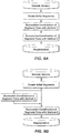
- FIG. 1 presents basic steps in some embodiments of the present inventive method.
- step 11 an initial segmentation is created for a given seismic dataset 10 . Details of this step are irrelevant for the present inventive method as long as the volume is decomposed into a plurality of, preferably many, mutually exclusive regions or initial segments that are nontrivial, i.e. span more than just one voxel, which experienced data interpreters will know how to provide, thus giving a guided and accelerated start to the process of combining segments.
- step 12 which may be performed before or after step 11 , the user or a computer algorithm selects the ultimate number of desired segments. Because for practical purposes the successive combination of segment pairs (step 13 ) will typically be performed on a computer, the computer needs to be instructed when to stop the process.
- step 13 pairs of segments are combined until the desired number of segments is reached. This is performed by any of several techniques, preferably one or more of those disclosed below.
- the resulting segmentation 14 is stored for analysis or visualization ( 15 ).
- Methods for the analysis of segments are disclosed separately from the different embodiments because the methods for analysis are independent of the specifics of the hierarchical segmentation method.
- a preferred embodiment of the basic Fig. 1 method involves setting the ultimate number of segments to be one, i.e. the progressive combination of segments is continued until one segment remains, spanning the entire volume. All the stages from the initial segmentation down to one segment are recorded and are thus retrievable states.
- the user or the algorithm may choose any state, for example in an interactive manner.
- the different states can be recorded either by, among other methods, re-labeling the individual voxels after each stage, by re-labeling the entries of a lookup table relating the initial segment labels to the segment labels at each stage, or preferably, by use of an equivalence table that only records which segments are merged at each stage.
- a lookuptable for each stage can be reconstructed by evaluating all equivalences up to this point.
- the recreated lookup table may then be used to re-label the voxels for storage, analysis, or visualization; to construct a color map for visualization; or to control opacity during visualization.
- the initial segments can be created in many different ways. Methods include thresholding, binning, or clustering the data; automatic feature tracking; or segmentation. For thresholding, either the user or an algorithm specifies a threshold value. All points with lower values are assigned to a background segment. The remaining voxels are converted to contiguous segments, for example by application of a connected component labeling algorithm. The case in which points with values exceeding the threshold are assigned to the background follows by analogy. These cases may be further generalized by binning the data into user or algorithm specified bins which creates initial segments that can be further refined with a connected component labeling algorithm. Primitives can be constructed by clustering of voxels from one or multiple datasets, or even recursively by clustering of other segments.
- Initial segments can be created by automated or assisted tracking using horizon trackers, horizon pickers, fault trackers, channel trackers, or seed picking.
- Horizons can be converted to segments by dilation (or thickening) of surfaces until another is encountered. The dilation can be performed in one direction only or simultaneously in multiple directions. Another method of converting horizons to segments is to assign the samples between horizons according to polarity or wavelet shape.
- Initial segments can also be created by preliminary segmentation by clustering or classification. All voxels in one segment are similar with respect to some characteristic or computed property while adjacent segments are significantly different with respect to the same characteristics.
- Clustering-based segmentation is an iterative technique that is used to partition a dataset into a specified number of clusters or objects. Histogram-based methods compute a histogram for some characteristic or property for the entire dataset and use the peaks and valleys in the histogram to locate the clusters or objects. A further refinement of this technique is to recursively apply the histogram-seeking method to clusters in the data in order to divide them into increasingly smaller clusters until no more clusters are formed.
- edge detection exploits the fact that region or object boundaries are often closely related to edges or relatively sharp property transitions. For seismic data, discontinuity, similarity, or differentiators serve as edge detectors. The edges identified by edge detection are often disconnected. To segment an object from a data volume, however, one needs closed region boundaries. Edge gaps are bridged if the distance between the two edges is within some predetermined threshold. Region growing methods take a set of seed points as input along with the data. The seeds mark each of the objects to be segmented. The regions are iteratively grown by comparing all unallocated neighboring voxels to the regions. This process continues until either all voxels are allocated to a region, or the remaining voxels exceed a threshold difference when compared to their neighbors.
- Level set methods or curve propagators evolve a curve or surface towards the lowest potential of a prescribed cost function, for example smoothness.
- the curves or surfaces either represent the desired objects, for example faults or channel axes; or they correspond to the boundaries of the desired objects, for example salt domes or channels. In the latter case, the curve appears to shrink wrap the object.
- Graphs can effectively be used for segmentation.
- a voxel, a group of voxels, or primordial objects are vertices and edges define the (dis)similarity among the neighborhood voxels or objects.
- Some popular algorithms of this category are random walker, minimum mean cut, minimum spanning tree-based algorithm, or normalized cut.
- the watershed transformation considers the data or their gradient magnitude as a (multidimensional) topographic surface.
- Voxels having the highest magnitudes correspond to watershed lines, which represent the segment boundaries. Water placed on any voxel enclosed by a common watershed line flows downhill to a common local minimum. Voxels draining to a common minimum form a catch basin, which represents a segment or object.
- Model-based segmentation methods assume that the objects of interest have a repetitive or predicable form of geometry. This geometric form is characterized with statistics that are used to control the segment growth.
- Scale-space segmentation or multi-scale segmentation is a general framework based on the computation of object descriptors at multiple scales of smoothing. Neural Network segmentation relies on processing small areas of a dataset using a neural network or a set of neural networks.
- the decision-making mechanism marks the areas of the dataset accordingly to the category recognized by the neural network.
- the user outlines the region of interest, for example by manual digitization with computer mouse, and algorithms are applied so that the path that best fits the edge of the object is shown.
- the listed methods here are just some examples for the generation of an initial segmentation. Many other methods can also be used.
- the initial segmentation method may create many thousands of initial segments; however some of the segments are larger than a single voxel. This is for reasons of computational efficiency and the geologic realism of the resulting layers or segments.
- Some of the embodiments of the invention require a list of neighbors around each segment. Even more restrictive, some embodiments require definition of linear sequence in which segments are combined. If all or most segments consist of single voxels, differentiation of voxels and/or neighborhoods is insufficient to define neighborhoods or to form such a sequence.
- the present disclosure provides a method that combines these initial segments into sets of stratigraphically or geophysically realistic layers or geobodies. Because stratigraphy is multi-cyclical, and thus hierarchical, a unique decomposition may not be desirable. Instead, a hierarchical multiresolution segmentation into nested layers or geobodies is more appropriate.
- the present invention fulfills at least this need
- segments for this embodiment correspond to layers or layer pieces, and thus, this embodiment combines thin layers into progressively thicker ones, which allows going from parasequence (sets) to sequences and sequence sets of various orders.
- the initial segments or initial layer pieces are topologically consistent. Strict topological consistency implies conditions with regard to the geometric arrangement of set of layers:
- the no-self-overlaps condition is actually a special case of the local consistency condition, and that the local consistency condition is a special case of the global consistency condition.
- the no self overlaps condition may be defined such that it applies to one layer piece or segment
- the local consistency condition may be defined such that it applies only when two different layer pieces or segments are involved
- the global consistency condition may be defined such that it applies only when at least three different layer pieces or segments are involved, in which case the three conditions are mutually exclusive.
- topological consistency of the thin layers is not a requirement for this embodiment of the inventive method of merging thin layers into larger units.
- the initial thin layers are topologically consistent which results in a stratigraphically more realistic segmentation or large scale layering.
- step 13 involves a staged combination of segments.
- the smallest segment is sought.
- its smallest neighbor is determined and these two segments are combined by either assigning them the same label, by updating a lookup table, or by recording their merge in an equivalence table, or by some equivalent bookkeeping technique for recording the combination.
- the size and neighbors for each segment are determined only once and recorded in tables instead of repeating this for every stage. In this way, the size and neighborhood tables are created initially, and then are updated after each stage of the segmentation.
- neighborhoods For a given segment, its neighborhood specifies the candidate segments for combination.
- the neighborhood may be defined once at the start of the hierarchical combination of segments or be updated periodically or at every stage to reflect that surrounding segments have been combined themselves.
- the neighborhood for a given segment is a list of directly touching segments, i.e., its neighbors.
- neighborhoods are restricted to only certain directions, for example only laterally or vertically.
- the neighborhood for a given segment may even contain segments that do not directly border the given segment, but simply list merge candidates, for example to specify a desired order or sequence in which segments are combined.
- the terms neighbor and neighborhood are not defined narrowly in the present disclosure.
- One variation of the size-guided embodiment is to limit the search for the smallest neighbor to only a selected part of the neighborhood, for example only segments that are either lateral or vertical neighbors.
- these two variations can be cascaded such that segments are first combined only in the lateral direction, which creates layers from layer pieces. These layer segments are then combined vertically in a second phase to create thicker layers or units that may correspond to sequences and sequence sets.
- One last variation of the size-guided embodiment is to limit each segment to have only two neighbors, for example one above and one below.
- the neighborhood table degenerates to a sequence or order between the segments. Progressive combinations of segments are limited to sequentially adjacent segments. This sequence or order may be constructed from the depths or stratigraphic ages of the segments.
- the sequence can be obtained from the analysis of the above/below relationships between the segments. The individual above/below relationships define a partial order that, for topologically consistent segments, allow creation of a total order consistent with the partial order.
- the smallest segment is merged with the smaller of its two consecutive neighbors. This is illustrated in Fig.
- segment or layer boundaries can be recognized as extremes on graphs of a segment property such as area or volume versus sequential segment number. Most extremes disappear when blurring the graph, and only the dominant ones remain as demonstrated in Fig. 4 , which allows segmentation of the sequence into increasingly thicker units.
- the initial segments are sequentially labeled, for example top down, by depth, or by their stratigraphic age.
- a property such as area or volume is computed for each segment.
- the segments corresponding to the local minima are merged with one of its sequentially adjacent segments, for example upwards, downwards, of with the smaller one.
- the properties are lightly blurred or smoothed, for example by application of a low-pass filter or short running-average filter.
- Most extrema will slightly move but can easily be related or tracked to one of the original extrema. Some extrema, however, vanish and the segments above and below the vanished extrema are combined. This procedure is repeated with another pass of blurring, extrema tracking, detection of vanishing extrema, and combination of the segments bracketing the vanished extrema; and so on until no extrema remain and thus all segments are combined into one.
- the graph of sequential segment number versus segment area exhibits many minima that separate layers. Tracking the minima during progressive smoothing of the graph determines the relevance of these layer boundaries. Minor minima correspond to minor boundaries separating segments that are combined early. Major minima can be tracked across many iterations of smoothing and correspond to major boundaries separating segments that are combined late. The "boundary number" indicates the order in which the extrema vanish and thus the order in which the directly adjacent segments are combined.
- the initial graph can be smoothed with progressively more aggressive filters.
- a virtual extrema can be inserted between the initial segments and the first combination step can be skipped. The virtual extrema are rapidly eliminated by the progressive filtering.
- the first step in the extrema-based option for doing step 13 is putting the initial segments into a list or sequence sorted, for example top-down, by their depth, or geologic age. Any sequence will suffice, with the understanding that eventually segments adjacent in this sequence will be merged, and thus the order of the initial segments in this sequence affects the final result. Preferably, segments that are spatially close will remain close in this sequence. A preferred sequence order is based on their geologic age, their order of deposition or creation, or an approximation thereof. Ideally, the segments are topologically consistent allowing generation of at least one such sequence consistent with the spatial relationships.
- a property or attribute is computed for each segment, for example area, number of voxels, or volume.
- segment properties can be computed using collocated values from at least one secondary dataset such as a seismic attribute volume, other geophysical or geologic data, or a geologic or engineering model. These values are sequentially placed in a property table or list.
- this list is modified, for example by application of a differentiator (high-pass filter) and/or integrator (low-pass filter).
- Extrema in this property table are used to define a first set of segments where the initial segments between two adjacent extrema are combined. These extrema can be either minima, maxima, or minima and maxima. Minima are used for the description of this technique, but the method is analogous for other extrema.
- the property list is slightly blurred by application of a modest low-pass or running average filter. Most minima will move to a slightly different location but can easily be tied to one of the original ones. Difficulties or ambiguities when tying minima back to the original ones indicate that the filter was too severe, and that the blurring should be redone with a slighter filter. Some minima may vanish, however, and the segments that are directly adjacent to the corresponding initial minima are combined.
- the step of blurring and combination of segments adjacent to vanishing minima is repeated until all minima have vanished.
- the steps of blurring, tracking, and combination do not need to be repeated in this order.
- the blurring is performed progressively using slight to severe filters or recursively using the same slight filter, and the different version of the blurred property are stored for example in a matrix or table.
- the minima are tracked through the matrix or table, and the stage at which a minima vanishes is recorded.
- the segments adjacent to a vanishing minima are combined, for example by updating a lookup table or recording in an equivalence table.
- a wavelet decomposition of the initial property table may be used.
- the segments are combined if they are similar with regard to some selected property or attribute.
- This attribute is preferably either based on the segments themselves, for example their geometries, or based on external data such as a secondary seismic volume.
- the most similar segments are combined first. For seismic data, combining the most similar segments first tends toward mega segments that rapidly grow and overtake the segmentation. In the later stages of the progressive segmentation, there tends to be one dominant segment with small embedded segments whose attributes or properties represent outliers in the distribution of attributes or properties.
- a difference in this alternative approach is that small segments are combined first. At each stage, the currently smallest segment is combined with its most similar neighbor.
- the initial segments from step 11 are first examined to create tables of size and respective neighbors.
- the method also computes one or multiple attributes for the individual segments based on the segments themselves. Such attributes include size, location, volume, moments, orientations, etc.
- the method then proceeds with a staged combination of similar or nearby segments, where similarity is computed using some similarity measure such as an L1-norm difference, least-squares (L2-norm) difference, or a Mahalanobis difference.
- L1-norm difference least-squares (L2-norm) difference
- a Mahalanobis difference a similarity measure
- the smallest segment at each stage is combined with its most similar neighbor, that combination is recorded, and the size, neighborhood, and attribute tables are updated.
- the attributes for the combined segment can be obtained by, for example, retaining the attributes from one or the other combined segments, by retaining the maximal or minimal ones, or by addition or multiplication of these attributes.
- the attributes for the combined segments may need to be computed anew.
- a preferred version of attribute-guided segment combination uses a secondary dataset to compute the segment attributes, for example another seismic data volume such as seismic envelope amplitude.
- the attribute could be the maxima, average, or the variance of the envelope amplitude contained in the segment.
- Other examples include seismic attribute volumes; geophysical data, for example seismic velocities, densities, or electrical resistivities; petrophysical data, for example porosity the sand/shale ratio; geological data, for example lithology or the environment of deposition; geologic models and simulations; reservoir simulations, for example pressures and fluid saturations; or engineering and production data, for example pressures or water cut.
- the method then proceeds with a staged combination of segments similar with respect to the attribute, where similarity is computed using some user- or computer-specified similarity measure.
- similarity is computed using some user- or computer-specified similarity measure.
- the smallest segment at each stage may be combined with its most similar neighbor, and the size, neighborhood, and attribute tables are updated.
- the attributes for the combined segment can be obtained from the attributes of the respective segments, or may need to be computed anew from the secondary data at the locations of the combined segment.
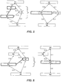
- Figure 5 presents an example of the attribute-guided merge without segment growth controlled by size as used for traditional segmentation. The most similar segments are combined and will slowly gobble up their neighbors. Large segments will themselves begin to combine until a few huge segments remain, inside which the most dissimilar initial segments linger as outliers.
- the arrows indicate neighboring segments and the numbers attached to the arrows indicate the similarity between individual segments. Segments 52 and 54 are most similar and thus, are merged into the new segment 52' .
- Fig. 6 An alternative to the example of Fig. 5 is presented in Fig. 6 .
- the currently smallest segment 63 is combined with its attribute-wise most similar neighbor 64 to constitute the new segment 63' , where the most similar neighbor is the one with the least attribute difference.
- This preferred alternative balances the segment growth ensuring that no segment captures most of the others during the early stages of the progressive combination of segments.
- the enabler-inhibitor option for performing the segment combination of step 13 introduces a distance function that encourages or inhibits the combination of any two segments.
- This distance between segments can either be computed from the segments, segment attributes, secondary data, or a combination thereof.
- One particular application of this embodiment is to imprint a bias against combination of certain pairs of segments.
- the distance function can be viewed as a generalization of the similarity measure used for attribute-guided combination.
- the distance function (or similarity measure) is stored in a distance table or distance matrix (or similarity table or similarity matrix) that is progressively being updated to account for the sequential combination of segments.
- One example is the use of seismic incoherency or discontinuity to discourage the merge of segments across faults or through zones of low data quality. In either case, there exists a barrier of high seismic incoherency that is used to amplify the segment distance.
- Another example is the use of previously identified surfaces such as stratigraphic unconformities or faults as barriers and distance amplifiers. The surfaces are obtained either by manual interpretation or application of an automatic detection algorithm.
- Concurrence refers to the concept that elements of related segments border each other more often than elements of unrelated ones.
- a classifier based on seismic texture or seismic attributes can easily generate hundreds of different classes. Multiple classes may correspond to one geophysical, geological or stratigraphic feature. Spatially, locations so classified tend to cluster together because they all correspond to the same or similar features. Moreover, many such features are not truly discrete but rather gradational such as an environment of deposition. Spatially, locations so classified tend to appear adjacent to each other. An example is the progression of depositional environments or elements from channel axis, to channel margin, and overbank deposits.
- the basic idea of the concurrence-based embodiment is to perform an initial segmentation or classification into many more segments or classes than ultimately desired. Segments do not need to be contiguous. This segmentation or classification is then refined by concurrence segmentation where segments or classes that are juxtaposed more often, with longer common borders or over longer distances, are preferably combined.
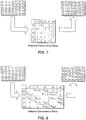
- step 11 After an initial segmentation (step 11), for example by texture analysis and classification, a determination is made of how much each segment borders the others, for example by counting the number of neighboring voxel pairs. This information may be used to generate a concurrence table. The method continues then with a staged combination of the most proximal segments, i.e. those with the largest common border, or equivalently, the segments with the largest entry in the concurrence table. After recording the combination and updating the concurrence table, the procedure is repeated until only the prescribed number of segments remains, for example, only one. An example of one such iteration is shown in Fig. 7 . There, the segments 21 and 22 with the highest concurrence count are merged into the new segment 21'. Concurrence-based segment combination tends to merge large segments because larger segments are more likely to have large common borders than smaller ones. A dominant background segment, for example, will grow rapidly by attracting large segments, while leaving the remaining small segments as isolated outliers.
- the concurrence table may be weighted, for example by the combined size (number of voxels) of the respective segments.
- Figure 8 shows an example of this where the segments 24 and 25 are merged instead of 21 and 22 as in Fig. 7 due to their larger ratio of common border to combined size. A dominant background segment is thus biased against by its large size, letting smaller segments merge first and thus this preferred variation creates more balanced segmentations.
- Other weighting options include but are not limited to the transformation of the concurrence matrix to a doubly stochastic (or bistochastic) matrix, multidimensional scaling (MDS), Sammon mapping, or Self-organized mapping (SOM).
- Hybrid options for performing the segment combination of step 13 relate to the idea that segmentation is applied in a cascaded or constrained manner, as depicted in Figs. 9A-B .
- cascaded mode Fig. 9A
- hierarchical segmentation is performed with one method up to some selected degree of segmentation, and then continued with another method, wherein one of the methods is extrema-based segment combination method.
- Small initial segments are merged with one embodiment to form intermediate segments that are then used as initial segments for the following merge to large segments with another embodiment.
- An example of the cascaded mode is the merge of initial segments to layers that are then combined into thick sequences.
- the initial segments are merged using a first method for performing segment combination to some intermediate stage of segmentation that serves as mask or constraint for an alternate segmentation.
- An alternate merge of the initial segments using a second method for performing segment combination is then executed with the constraint of never merging segments belonging to different intermediate regions, wherein the first method is the extrema-based segment combination and the second method is one of the options for performing segment combination, or the first method is one of the options for performing segment combination and the second method is the extrema-based segment combination.
- the intermediate segments act as masks or constraints for the second hierarchical segmentation.
- An example of the constrained mode is the construction of sequence-bound geobodies. First, the initial segments are merged to define large-scale sequences. The merge is then restarted with the constraint that each resulting segment belongs to only one sequence. An alternative is to gather all the initial segments belonging to a particular sequence and to perform the merge of only these initial segments.
- the present inventive method begins with a large number of segments (step 11) and then performs a staged segment combination (step 13).
- One application of this staged or hierarchical segmentation is to analyze the segments for their hydrocarbon potential, and then to create a ranked list of targets based on their hydrocarbon potential, or presence or quality of at least some elements of a hydrocarbon system, for example, source, maturation, migration, reservoir, seal, or trap.
- performance of this analysis at different stages of the hierarchical segmentation allows or at least aids the determination of the necessary or optimal number of segments, and thus, selection of an appropriate degree of segmentation. Since all the states of the segmentation from the initial segmentation to the final number of segments, possibly one, are recorded for example in the lookup or equivalence tables, some or all states can be reconstructed for analysis to determine characteristic degrees of segmentation.
- Analysis of the segments includes defining or selecting one or more measures that will be used to rank or high-grade the segments.
- the measure may be any combination of the segment geometries, properties of collocated secondary data, and relations between the segments.
- Geometric measures for segments refer to location, time or depth, size, length, area, cross section, volume, orientation, or shape. These measures also may include an inertia tensor; raw, central, scale- and rotation-invariant moments; or covariance. Other measures are based on the segment boundaries and include local or average curvatures, ratios between surface area and volume, or decomposition into spherical harmonics.
- Collocated property measures are built by querying a dataset at the locations occupied by the segment. For example, one can extract the values from a collocated seismic or attribute dataset such as amplitude, seismic texture classification, or a collocated geologic model such as porosity or environment of deposition, and compute a statistical measure for these values. Statistical measures include average, median, mode, extrema, or variance; or raw, central, scale- and rotation-invariant property-weighted moments. If two collocated properties are extracted, then a measure can be computed by correlation of the collocated values, for example porosity and hydraulic permeability extracted from collocated geologic models.
- Measures include the distance or similarity to neighboring segments; the total number of neighboring segments, or the number of neighboring segments above or below a given segment.
- DHIs direct hydrocarbon indicators
- An example of such a DHI is amplitude fit to structure.
- the effect of gravity on the density differences between fluid types generates a fluid contact that is generally flat.
- reflection strength changes when crossing a fluid contact.
- Correlating the voxel depths within a segment with seismic attributes such as collocated amplitude strength facilitates rapid screening of all segments in a volume for evidence of fluid contacts, and thus, the presence of hydrocarbons.
- seismic DHI-based measures for the analysis of segments include amplitude anomalies, amplitude versus offset (AVO) effects, phase changes or polarity reversals, and fluid contacts or common termination levels.
- Other geophysical hydrocarbon evidence includes seismic velocity sags, and frequency attenuation; also, electrical resistivity.
- Amplitude anomaly refers to amplitude strength relative to the surrounding background amplitudes as well as their consistency and persistence in one amplitude volume, for example, the full stack. A bright amplitude anomaly has amplitude magnitudes larger than the background, while a dim anomaly has amplitude magnitudes smaller than the background.
- Comparison of seismic amplitudes at the segment location against an estimated background trend allows high-grading based on the anomalous amplitude strength DHI measure. For large segments, presence of an amplitude anomaly surrounded by background amplitudes express themselves with bi- or multi-modal histograms that can be detected by performance of a multi-modal histogram decomposition.
- An AVO Class 1 has a clearly discernable positive reflection amplitude on the near-stack data with decreasing amplitude magnitudes on the mid- and far stack data, respectively.
- An AVO Class 2 has nearly vanishing amplitude on the near-stack data, and either a decreasing positive amplitude with offset or progressively increasing negative amplitude values on the mid- and far-stack data.
- An AVO class 3 exhibits strong negative amplitudes on the near-stack data growing progressively more negative with increasing offset.
- An AVO Class 4 exhibits very strong, nearly constant negative amplitudes at all offsets.
- amplitude persistence or consistency within a segment is used as a secondary measure within each of the AVO classes. Comparison of partial offset- or angle-stacks at the location of the segments allows classification by AVO behavior, and thus, high-grading based on the AVO DHI measure.
- An alternative to partial stacks is the estimation of the AVO parameters A (intercept) and B (gradient) from prestack (offset) gathers at the locations of the segments, and use of these parameters for AVO classification or computation of a measure such as A * B or A + B .
- a fluid contact implies a fluid change for example from hydrocarbon gas to water.
- a fluid contact can generate a relatively flat reflection response embedded in a segment.
- Cross-plotting or crosscorrelation of seismic attributes versus depth within a segment allows identification or highlighting of fluid contacts, for example from a depth with extremal attributes or extremal attribute variance.
- the boundary between reservoir seal and water-filled reservoir is a seismic surface with positive polarity
- the boundary between seal and gas-filled reservoir is a surface with negative polarity.
- the seal-reservoir boundary corresponds to a surface exhibiting a polarity change from shallow to deep across the fluid contact.
- Comparison of the wavelet polarity or estimation of the instantaneous wavelet phase within a segment allows identification of segments exhibiting a polarity-reversal or phasechange DHI.
- An abrupt down dip termination of many nearby segments or a locally persistent abrupt change of amplitudes within the segments are yet more examples of direct hydrocarbon indicators that can be quantified from segments.
- the termination depths of adjacent segments are compared or correlated to allow identification of a set of segments exhibiting an abrupt down-dip termination DHI measure.
- Hydrocarbon gas also leads to a decrease of the speed of seismic waves that is detectable by seismic inversion, traveltime tomography, or velocity analysis. Segments containing gas will have velocities lower than that suggested by the regional trend.
- segment combining in the present inventive method enables a useful type of visualization and analysis.
- Segments consist of smaller segments. At later stages, segments consist of two or more segments that were earlier combined. The small segments that form a larger one are analyzed separately and the results are combined, correlated, or contrasted. Another method of component-segment analysis is to examine their spatial relationships. Different analyses of segments and their sub-segments yield different measures.
- Selection criteria include thresholding, ranking, prioritizing, classification, or matching.
- a first approach might be to apply a threshold to the measures and select all segments either exceeding or undercutting the threshold.
- Another high-grading method is ranking the segments in accordance to their measures, and then selecting the top ranked segments, the top ten segments for example.
- a special case of ranking is prioritizing, where all segments are selected but associated with their rank, for example through their label or a database.
- Subsequent analyses commence with the highest-ranked segment and then go through the segments in accordance to their priorities until a prescribed number of acceptable segments are identified, or until time and/or resource constraints require termination of further activities.
- Having one or more measures for each segment also allows determination of appropriate levels of segmentation. Given one or multiple measures or analyses allows, for example, the association of this particular segmentation stage with a measure describing the segmentation at this stage.
- entropy will typically exhibit a pronounced change, indicating that the merge that prompted that change may be somewhat more questionable than the preceding merges that tended to produce a more-or-less continuous decline in entropy.
- Figure 10 illustrates this with a schematic curve of entropy versus degree (stage) of segmentation, as quantified by the remaining number of segments.
- stage degree of segmentation
- the entropy changes its behavior.
- These stages may be called characteristic stages, having a characteristic number of segments.
- the four characteristic stages could correspond to a segmentation into parasequences, parasequence sets, sequences, and sequence sets.
- Segment volume relative to the entire seismic volume is one way to define the shifted and scaled measures for the entropy computation, but any measure shifted to be positive and scaled to sum up to one can be used.
- Other examples include the relative number of component segments, the relative variability of some attribute inside the segments, or the surface to volume ratio.
- measures other than entropy can be used to characterize or summarize the different segmentation stages.
- One other example is to compute the statistical significance of a given segmentation stage, i.e., the estimation whether some or all segments at this stage are statistically significantly different or conversely, the estimation of the likelihood that measures or analyses for some or all of the segments at this stage are statistically the same.
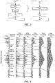
- Figure 11 presents one slice through this dataset, with seismic amplitude values indicated by the gray scale.
- An initial partitioning based on polarity, followed by connectivity analysis and splitting of large, topologically inconsistent components yielded an initial segmentation with 32,974 segments.
- Figure 12 shows a slice at the same location through the initial segmentation volume.
- the gray scale used to satisfy patent requirements has been repeated (wrapped) multiple times over in an attempt to delineate the vast number of initial segments.
- the size-guided option for performing the segment combination of step 13 the currently smallest segment is combined with its smallest neighbor, and this process is repeated until all segments are combined.
- Figures 13 and 14 show the slice trough the data volume at the segment combination stages with 16 and 4 remaining segments or layers, respectively.
- Segmentation of the Fig. 11 data volume was then performed twice more, using different Step 13 segment combination options.
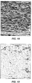
- instantaneous amplitude shown in Fig. 15
- Figure 16 shows the stage of 16 remaining segments. The segmentation is interfingered and not as layered as the size-guided result in Fig. 13 .
- Fig. 17 presents the 16 segments stage obtained with a hybrid combinatorial option.
- the size-guided option is used to combine the initial segmentation to 4 gross layers.
- these gross layers are used as masks to restrict the segment growth when using the attribute-guided option to combine the initial segmentation into 16 remaining segments.
- a second example application of the present inventive method demonstrates the concurrence-based option for combining segment pairs, using a seismic data volume with a size of 501 ⁇ 301 ⁇ 71 voxels.
- Figure 18 shows an initial segmentation that contains 41 different classes of segments. There are more segments than classes because the segments do not need to be connected or contiguous. After computation of the concurrence table that states how often the different segment classes border each other, the segment classes are progressively combined using the unweighted concurrence table.
- Figure 19 shows the stage with five remaining segment classes (indicated by different shades of gray) where there are more than five segments because individual segment classes are not required to form contiguous bodies.
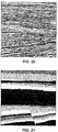
- the last example application demonstrates extrema-based combination using a seismic dataset with a size of 1226 ⁇ 211 ⁇ 131 voxels.
- the initial segmentation containing 71,796 segments is shown in Fig. 20 .
- the progression of the segment areas under progressive smoothing is shown in Fig. 4 , which also shows some of the more relevant extrema in the area versus segment or sequence number graph.
- Fig. 21 shows the portioning of the initial segmentation ( Fig. 20 ) to 16 segments or layers using extrema-based combination.
Landscapes
- Physics & Mathematics (AREA)
- Life Sciences & Earth Sciences (AREA)
- Engineering & Computer Science (AREA)
- Remote Sensing (AREA)
- General Life Sciences & Earth Sciences (AREA)
- General Physics & Mathematics (AREA)
- Geophysics (AREA)
- Acoustics & Sound (AREA)
- Environmental & Geological Engineering (AREA)
- Geology (AREA)
- Geophysics And Detection Of Objects (AREA)
Claims (22)
- Procédé d'analyse d'un volume de données géophysiques obtenu ou déduit à partir d'une prospection géophysique d'une région souterraine pour déterminer la structure physique de la région souterraine, comprenant :(a) la division (11) du volume de données en une pluralité N de segments initiaux ;(b) la combinaison successive (13) de paires de segments jusqu'à ce que le nombre de segments soit réduit à un nombre sélectionné M, où M < N ; et(c) l'analyse (15) de certains ou la totalité des segments M, ou de segments provenant d'un stade de combinaison intermédiaire, pour interpréter la structure physique souterraine ;le procédé étant mis en œuvre par ordinateur, et au moins la combinaison successive (13) de paires de segments étant réalisée au moyen de l'ordinateur ;
CARACTERISE EN CE QUE :(i) au moins un des segments initiaux de la pluralité N de segments initiaux a une taille supérieure à un voxel ; et(ii) la combinaison (13) de paires de segments comprend :- la mise en séquence des segments initiaux par une règle de séquence sélectionnée ;- le tracé d'un graphe du nombre séquentiel de séquences en fonction de la taille de segment ;- le lissage du graphe une pluralité de fois et le suivi des limites de nombre de segment qui survivent et de celles qui disparaissent à chaque stade de lissage ; et- l'utilisation de l'ordre de disparition de limites pour déterminer l'ordre de combinaison (13) de paires de segments correspondantes. - Procédé de la revendication 1, dans lequel M = 1, et un enregistrement de combinaison montrant les segments restants après chaque combinaison de paires de segments (13) est conservé.
- Procédé de la revendication 1, dans lequel les segments initiaux sont cohérents au niveau topologique.
- Procédé de la revendication 3, dans lequel les segments d'un bout à l'autre de la combinaison (13) sont cohérents au niveau topologique, ce qui signifie que les combinaisons qui violeraient la cohérence topologique ne sont pas réalisées.
- Procédé de la revendication 1, dans lequel un procédé supplémentaire de sélection de paires de segments à combiner (13) est utilisé dans la réduction de N segments à M segments.
- Procédé de la revendication 5, dans lequel un premier procédé est utilisé pour combiner (13) des paires jusqu'à ce qu'un stade de combinaison sélectionné soit atteint, puis les segments définis à ce stade de combinaison (13) sont utilisés comme masques pour contraindre une combinaison successive (13) des N segments initiaux en utilisant un deuxième procédé de combinaison (13), dans lequel le premier procédé est le procédé de combinaison de paires de segments selon la revendication 1 (ii) et le deuxième procédé est le procédé supplémentaire, ou dans lequel le premier procédé est le procédé supplémentaire et le deuxième procédé est le procédé de combinaison de paires de segments selon la revendication 1 (ii).
- Procédé de la revendication 5, dans lequel le procédé supplémentaire est caractérisé en ce que : la combinaison (13) est réalisée par combinaison successive d'un segment le plus petit avec son voisin le plus petit.
- Procédé de la revendication 7, dans lequel une taille et des voisins de segment sont déterminés une seule fois et enregistrés dans des tables qui sont mises à jour après chaque stade de la combinaison successive (13).
- Procédé de la revendication 7, dans lequel un voisin est limité à un voisin latéral à un ou plusieurs stades de combinaison sélectionnés (13), ou un voisin est limité à un voisin vertical à un ou plusieurs stades de combinaison sélectionnés (13).
- Procédé de la revendication 5, dans lequel le procédé supplémentaire est caractérisé en ce que : les segments de chaque paire de segments qui est combinée (13) sont des voisins les plus similaires, et la similitude est basée sur une valeur pour chaque segment d'un attribut sélectionné des données géophysiques.
- Procédé de la revendication 10, dans lequel chaque paire de segments qui est combinée contient également le segment le plus petit à ce moment.
- Procédé de la revendication 5, dans lequel le procédé supplémentaire est caractérisé en ce que : la distance entre deux segments est utilisée comme un facteur pour favoriser ou défavoriser la combinaison (13) des deux segments.
- Procédé de la revendication 5, dans lequel le procédé supplémentaire est caractérisé en ce que : la connectivité entre deux segments est utilisée comme un facteur pour favoriser ou défavoriser la combinaison (13) des deux segments.
- Procédé de la revendication 5, dans lequel le procédé supplémentaire est caractérisé en ce que : la séquence de combinaison (13) de paires de segments est basée sur une concomitance, ce qui signifie une étendue de la limite commune de chaque paire.
- Procédé de la revendication 14, dans lequel les valeurs de concomitance sont pondérées par une fonction de pondération sélectionnée.
- Procédé de la revendication 1, dans lequel l'analyse (15) des M segments comprend un écrémage, un classement ou une priorisation des M segments sur la base d'une ou plusieurs mesures sélectionnées dans un groupe constitué par des propriétés géométriques de segment, des indicateurs directs d'hydrocarbures ou DHI, et d'autres données secondaires colocalisées avec les M segments.
- Procédé de la revendication 16, comprenant en outre l'utilisation de la ou des mesures après une pluralité de stades de combinaison (13) pour déterminer un stade de combinaison optimal pour l'analyse (15).
- Procédé de la revendication 17, dans lequel la détermination d'un stade de combinaison optimal pour l'analyse (15) comprend l'utilisation de ladite ou desdites mesures pour calculer une valeur d'entropie pour chacun de la pluralité de stades, puis l'utilisation des valeurs d'entropie pour déterminer un stade de combinaison optimal pour l'analyse (15).
- Procédé de la revendication 1, dans lequel l'analyse (15) des M segments comprend l'analyse de petits segments combinés pour en former de plus grands, et la combinaison, la corrélation ou la mise en contraste des résultats.
- Procédé de la revendication 1 dans lequel, dans la combinaison (13) de paires de segments, chaque segment ne peut être combiné (13) qu'avec un seul d'une liste prescrite de voisins.
- Procédé de la revendication 1, dans lequel l'interprétation de la structure physique souterraine comprend la recherche dans un affichage de segments de l'indication d'un ou plusieurs corps géologiques qui représentent potentiellement des accumulations d'hydrocarbures.
- Procédé de production d'hydrocarbures à partir d'une région souterraine, comprenant :(a) l'obtention d'un volume de données géophysiques (10) à partir d'une prospection de la région souterraine ;(b) l'analyse du volume de données géophysiques pour déterminer la structure physique de la région souterraine, au moyen d'un procédé tel que décrit dans la revendication 1 ; et(c) le forage d'un puits dans la région souterraine au moins en partie sur la base de l'analyste précédente, et la production d'hydrocarbures à partir du puits.
Applications Claiming Priority (2)
| Application Number | Priority Date | Filing Date | Title |
|---|---|---|---|
| US25840509P | 2009-11-05 | 2009-11-05 | |
| PCT/US2010/051902 WO2011056347A1 (fr) | 2009-11-05 | 2010-10-08 | Procédé permettant de créer un modèle terrestre à strates hiérarchisées |
Publications (3)
| Publication Number | Publication Date |
|---|---|
| EP2496967A1 EP2496967A1 (fr) | 2012-09-12 |
| EP2496967A4 EP2496967A4 (fr) | 2017-11-08 |
| EP2496967B1 true EP2496967B1 (fr) | 2021-11-17 |
Family
ID=43970235
Family Applications (1)
| Application Number | Title | Priority Date | Filing Date |
|---|---|---|---|
| EP10828732.7A Active EP2496967B1 (fr) | 2009-11-05 | 2010-10-08 | Procédé permettant de créer un modèle terrestre à strates hiérarchisées |
Country Status (5)
| Country | Link |
|---|---|
| US (1) | US9366772B2 (fr) |
| EP (1) | EP2496967B1 (fr) |
| AU (1) | AU2010315735B2 (fr) |
| CA (1) | CA2776930C (fr) |
| WO (1) | WO2011056347A1 (fr) |
Families Citing this family (41)
| Publication number | Priority date | Publication date | Assignee | Title |
|---|---|---|---|---|
| US9377548B2 (en) * | 2011-11-09 | 2016-06-28 | Chevron U.S.A. Inc. | Wavelet-transform based system and method for analyzing characteristics of a geological formation |
| US9121964B2 (en) * | 2012-01-13 | 2015-09-01 | Westerngeco L.L.C. | Parameterizing a geological subsurface feature |
| CN104067313B (zh) * | 2012-01-16 | 2019-02-01 | 皇家飞利浦有限公司 | 成像装置 |
| US20130261981A1 (en) * | 2012-04-03 | 2013-10-03 | Westerngeco L.L.C. | Covariance estimation using sparse wavelet representation |
| US9299191B2 (en) * | 2012-06-04 | 2016-03-29 | Google Inc. | Adaptive artifact removal |
| AU2013338553B2 (en) * | 2012-11-02 | 2017-03-02 | Exxonmobil Upstream Research Company | Analyzing seismic data |
| JP6105903B2 (ja) * | 2012-11-09 | 2017-03-29 | キヤノン株式会社 | 画像処理装置、画像処理方法、放射線撮影システム及びプログラム |
| US9417349B1 (en) * | 2013-02-13 | 2016-08-16 | Ihs Global Inc. | Picking faults in a seismic volume using a cost function |
| US10663609B2 (en) * | 2013-09-30 | 2020-05-26 | Saudi Arabian Oil Company | Combining multiple geophysical attributes using extended quantization |
| US20160292320A1 (en) * | 2014-04-08 | 2016-10-06 | Hess Corporation | Improved methods and systems for modelling geological formations |
| CN104977628B (zh) * | 2014-04-11 | 2017-08-18 | 中国石油化工股份有限公司 | 地质层位片段自动组合方法 |
| US9501740B2 (en) * | 2014-06-03 | 2016-11-22 | Saudi Arabian Oil Company | Predicting well markers from artificial neural-network-predicted lithostratigraphic facies |
| US10995592B2 (en) * | 2014-09-30 | 2021-05-04 | Exxonmobil Upstream Research Company | Method and system for analyzing the uncertainty of subsurface model |
| GB2533847B (en) * | 2014-11-06 | 2017-04-05 | Logined Bv | Local layer geometry engine with work zone generated from buffer defined relative to a wellbore trajectory |
| US10267934B2 (en) | 2015-01-13 | 2019-04-23 | Chevron U.S.A. Inc. | System and method for generating a depositional sequence volume from seismic data |
| US10425350B1 (en) | 2015-04-06 | 2019-09-24 | EMC IP Holding Company LLC | Distributed catalog service for data processing platform |
| US10706970B1 (en) | 2015-04-06 | 2020-07-07 | EMC IP Holding Company LLC | Distributed data analytics |
| US10791063B1 (en) | 2015-04-06 | 2020-09-29 | EMC IP Holding Company LLC | Scalable edge computing using devices with limited resources |
| US10776404B2 (en) | 2015-04-06 | 2020-09-15 | EMC IP Holding Company LLC | Scalable distributed computations utilizing multiple distinct computational frameworks |
| US10860622B1 (en) * | 2015-04-06 | 2020-12-08 | EMC IP Holding Company LLC | Scalable recursive computation for pattern identification across distributed data processing nodes |
| US10277668B1 (en) | 2015-04-06 | 2019-04-30 | EMC IP Holding Company LLC | Beacon-based distributed data processing platform |
| US10656861B1 (en) | 2015-12-29 | 2020-05-19 | EMC IP Holding Company LLC | Scalable distributed in-memory computation |
| US10891786B2 (en) * | 2016-10-11 | 2021-01-12 | Hewlett-Packard Development Company, L.P. | Generating data for a three-dimensional (3D) printable object, including a truss structure |
| WO2018080745A1 (fr) | 2016-10-28 | 2018-05-03 | Exxonmobil Upstream Research Company | Procédé et système pour l'amélioration du maillage d'un modèle souterrain |
| US10484675B2 (en) * | 2017-04-16 | 2019-11-19 | Facebook, Inc. | Systems and methods for presenting content |
| US11748877B2 (en) | 2017-05-11 | 2023-09-05 | The Research Foundation For The State University Of New York | System and method associated with predicting segmentation quality of objects in analysis of copious image data |
| EP3673298A1 (fr) * | 2017-08-25 | 2020-07-01 | ExxonMobil Upstream Research Company | Interprétation sismique automatisée faisant appel à des réseaux de neurones entièrement à convolution |
| US11555937B2 (en) * | 2018-06-22 | 2023-01-17 | Exxonmobil Upstream Research Company | Method and system for generating simulation grids by mapping a grid from the design space |
| CN112400123B (zh) * | 2018-07-05 | 2024-03-29 | 吉奥奎斯特系统公司 | 用于盐地震解译的级联式机器学习工作流 |
| US11693139B2 (en) | 2018-12-11 | 2023-07-04 | ExxonMobil Technology and Engineering Company | Automated seismic interpretation-guided inversion |
| EP3894905A2 (fr) | 2018-12-11 | 2021-10-20 | ExxonMobil Upstream Research Company | Systèmes et procédés d'interprétation sismique automatisée pour l'apprentissage et l'inférence en continu de caractéristiques géologiques |
| CA3122684C (fr) | 2018-12-11 | 2023-12-19 | Exxonmobil Upstream Research Company | Augmentation de donnees destinee a des systemes et procedes d'interpretation sismique |
| US11320551B2 (en) | 2018-12-11 | 2022-05-03 | Exxonmobil Upstream Research Company | Training machine learning systems for seismic interpretation |
| CA3122686C (fr) | 2018-12-11 | 2023-10-24 | Exxonmobil Upstream Research Company | Modelisation de reservoir automatisee au moyen de reseaux generatifs profonds |
| CN109581487B (zh) * | 2018-12-17 | 2020-12-11 | 中国海洋石油集团有限公司 | 一种沉积体波形空间结构分析与体控反演建模方法 |
| GB2579854B (en) * | 2018-12-18 | 2021-06-16 | Equinor Energy As | Method of analysing seismic data to detect hydrocarbons |
| US11360224B2 (en) * | 2019-05-03 | 2022-06-14 | Exxonmobil Upstream Research Company | Inversion, migration, and imaging related to isotropic wave-mode- independent attenuation |
| CN110544286B (zh) * | 2019-06-28 | 2024-02-27 | 中国再保险(集团)股份有限公司 | 一种大尺度范围的场地快速分类方法及构建场地分类图的装置 |
| US11169287B2 (en) | 2020-03-27 | 2021-11-09 | Saudi Arabian Oil Company | Method and system for automated velocity model updating using machine learning |
| CN114594512A (zh) * | 2020-12-03 | 2022-06-07 | 中国石油天然气股份有限公司 | 地震数据有序性评估方法及装置 |
| US11668848B2 (en) | 2021-06-24 | 2023-06-06 | Saudi Arabian Oil Company | Method and system for seismic imaging using S-wave velocity models and machine learning |
Family Cites Families (73)
| Publication number | Priority date | Publication date | Assignee | Title |
|---|---|---|---|---|
| US4916615A (en) | 1986-07-14 | 1990-04-10 | Conoco Inc. | Method for stratigraphic correlation and reflection character analysis of setsmic signals |
| US5047991A (en) | 1989-04-28 | 1991-09-10 | Schlumberger Technology Corporation | Lithology identification using sonic data |
| US4992995A (en) | 1989-10-24 | 1991-02-12 | Amoco Corporation | Methods for attenuating noise in seismic data |
| US5274714A (en) | 1990-06-04 | 1993-12-28 | Neuristics, Inc. | Method and apparatus for determining and organizing feature vectors for neural network recognition |
| US5265192A (en) | 1990-09-20 | 1993-11-23 | Atlantic Richfield Company | Method for the automated editing of seismic traces using an adaptive network |
| US5444619A (en) | 1993-09-27 | 1995-08-22 | Schlumberger Technology Corporation | System and method of predicting reservoir properties |
| US5416750A (en) | 1994-03-25 | 1995-05-16 | Western Atlas International, Inc. | Bayesian sequential indicator simulation of lithology from seismic data |
| GB2322704B (en) | 1994-07-07 | 1998-12-09 | Geco As | Method of Processing seismic data |
| US5563949A (en) * | 1994-12-12 | 1996-10-08 | Amoco Corporation | Method of seismic signal processing and exploration |
| US5586082A (en) | 1995-03-02 | 1996-12-17 | The Trustees Of Columbia University In The City Of New York | Method for identifying subsurface fluid migration and drainage pathways in and among oil and gas reservoirs using 3-D and 4-D seismic imaging |
| US5539704A (en) | 1995-06-23 | 1996-07-23 | Western Atlas International, Inc. | Bayesian sequential Gaussian simulation of lithology with non-linear data |
| FR2738920B1 (fr) | 1995-09-19 | 1997-11-14 | Elf Aquitaine | Methode de reconnaissance automatique de facies sismiques |
| US6052650A (en) | 1997-02-27 | 2000-04-18 | Schlumberger Technology Corporation | Enforcing consistency in geoscience models |
| US6466923B1 (en) | 1997-05-12 | 2002-10-15 | Chroma Graphics, Inc. | Method and apparatus for biomathematical pattern recognition |
| GB9904101D0 (en) | 1998-06-09 | 1999-04-14 | Geco As | Subsurface structure identification method |
| GB9819910D0 (en) | 1998-09-11 | 1998-11-04 | Norske Stats Oljeselskap | Method of seismic signal processing |
| US6236942B1 (en) | 1998-09-15 | 2001-05-22 | Scientific Prediction Incorporated | System and method for delineating spatially dependent objects, such as hydrocarbon accumulations from seismic data |
| US6278949B1 (en) | 1998-11-25 | 2001-08-21 | M. Aftab Alam | Method for multi-attribute identification of structure and stratigraphy in a volume of seismic data |
| DE19943325C2 (de) | 1999-09-10 | 2001-12-13 | Trappe Henning | Verfahren zur Bearbeitung seismischer Meßdaten mit einem neuronalen Netzwerk |
| US6295504B1 (en) | 1999-10-25 | 2001-09-25 | Halliburton Energy Services, Inc. | Multi-resolution graph-based clustering |
| US6226596B1 (en) | 1999-10-27 | 2001-05-01 | Marathon Oil Company | Method for analyzing and classifying three dimensional seismic information |
| US6574566B2 (en) | 1999-12-27 | 2003-06-03 | Conocophillips Company | Automated feature identification in data displays |
| US6363327B1 (en) | 2000-05-02 | 2002-03-26 | Chroma Graphics, Inc. | Method and apparatus for extracting selected feature information and classifying heterogeneous regions of N-dimensional spatial data |
| US6618678B1 (en) | 2000-05-26 | 2003-09-09 | Jason Geosystems B.V. | Method of joint analysis and interpretation of the subsurface from multiple seismic derived layer property data sets |
| US6625541B1 (en) | 2000-06-12 | 2003-09-23 | Schlumberger Technology Corporation | Methods for downhole waveform tracking and sonic labeling |
| FR2813959B1 (fr) | 2000-09-11 | 2002-12-13 | Inst Francais Du Petrole | Methode pour faciliter la reconnaissance d'objets, notamment geologiques, par une technique d'analyse discriminante |
| US6560540B2 (en) | 2000-09-29 | 2003-05-06 | Exxonmobil Upstream Research Company | Method for mapping seismic attributes using neural networks |
| US6438493B1 (en) | 2000-09-29 | 2002-08-20 | Exxonmobil Upstream Research Co. | Method for seismic facies interpretation using textural analysis and neural networks |
| US6950786B1 (en) | 2000-10-10 | 2005-09-27 | Schlumberger Technology Corporation | Method and apparatus for generating a cross plot in attribute space from a plurality of attribute data sets and generating a class data set from the cross plot |
| US7006085B1 (en) | 2000-10-30 | 2006-02-28 | Magic Earth, Inc. | System and method for analyzing and imaging three-dimensional volume data sets |
| US6631202B2 (en) | 2000-12-08 | 2003-10-07 | Landmark Graphics Corporation | Method for aligning a lattice of points in response to features in a digital image |
| GB2386455B (en) | 2000-12-18 | 2005-05-04 | Schlumberger Holdings | Seismic signal processing method and apparatus for generating correlation spectral volumes to determine geologic features |
| US6597994B2 (en) | 2000-12-22 | 2003-07-22 | Conoco Inc. | Seismic processing system and method to determine the edges of seismic data events |
| US6473696B1 (en) | 2001-03-13 | 2002-10-29 | Conoco Inc. | Method and process for prediction of subsurface fluid and rock pressures in the earth |
| US6823266B2 (en) * | 2001-06-20 | 2004-11-23 | Exxonmobil Upstream Research Company | Method for performing object-based connectivity analysis in 3-D seismic data volumes |
| DE10142785C2 (de) | 2001-08-31 | 2003-07-03 | Henning Trappe | Verfahren zur Bestimmung lokaler Ähnlichkeit aus seismischen 3D-Meßdaten |
| US6957146B1 (en) | 2001-12-24 | 2005-10-18 | Rdsp I, L.P. | System for utilizing seismic data to estimate subsurface lithology |
| US7145570B2 (en) | 2002-03-11 | 2006-12-05 | Sun Microsystems, Inc. | Magnified texture-mapped pixel performance in a single-pixel pipeline |
| US6674689B2 (en) * | 2002-04-12 | 2004-01-06 | Exxonmobil Upstream Research Company | Method for morphologic analysis of seismic objects |
| FR2841344B1 (fr) | 2002-06-19 | 2005-04-29 | Tsurf | Procede, dispositif et produit-programme de lissage d'une propriete de subsurface |
| US7523394B2 (en) | 2002-06-28 | 2009-04-21 | Microsoft Corporation | Word-processing document stored in a single XML file that may be manipulated by applications that understand XML |
| US7162463B1 (en) | 2002-07-12 | 2007-01-09 | Chroma Energy, Inc. | Pattern recognition template construction applied to oil exploration and production |
| US20060184488A1 (en) | 2002-07-12 | 2006-08-17 | Chroma Energy, Inc. | Method and system for trace aligned and trace non-aligned pattern statistical calculation in seismic analysis |
| US7308139B2 (en) | 2002-07-12 | 2007-12-11 | Chroma Energy, Inc. | Method, system, and apparatus for color representation of seismic data and associated measurements |
| US7188092B2 (en) | 2002-07-12 | 2007-03-06 | Chroma Energy, Inc. | Pattern recognition template application applied to oil exploration and production |
| US20050288863A1 (en) | 2002-07-12 | 2005-12-29 | Chroma Energy, Inc. | Method and system for utilizing string-length ratio in seismic analysis |
| US7184991B1 (en) | 2002-07-12 | 2007-02-27 | Chroma Energy, Inc. | Pattern recognition applied to oil exploration and production |
| US7295706B2 (en) | 2002-07-12 | 2007-11-13 | Chroma Group, Inc. | Pattern recognition applied to graphic imaging |
| BR0318292A (pt) * | 2002-09-26 | 2006-07-11 | Exxonmobil Upstream Res Co | método para a realização de detecção de semente baseada de forma estratigráfica em um volume de dados sìsmicos 3-d |
| GB2394050B (en) | 2002-10-07 | 2005-11-23 | Westerngeco Seismic Holdings | Processing seismic data |
| US6912467B2 (en) * | 2002-10-08 | 2005-06-28 | Exxonmobil Upstream Research Company | Method for estimation of size and analysis of connectivity of bodies in 2- and 3-dimensional data |
| GB2400664B (en) | 2003-04-10 | 2005-05-25 | Schlumberger Holdings | Extrema classification |
| US6804609B1 (en) | 2003-04-14 | 2004-10-12 | Conocophillips Company | Property prediction using residual stepwise regression |
| US6970397B2 (en) | 2003-07-09 | 2005-11-29 | Gas Technology Institute | Determination of fluid properties of earth formations using stochastic inversion |
| US7243029B2 (en) | 2003-08-19 | 2007-07-10 | Apex Spectral Technology, Inc. | Systems and methods of hydrocarbon detection using wavelet energy absorption analysis |
| US7453767B1 (en) | 2003-11-25 | 2008-11-18 | Michael John Padgett | Method for deriving a 3D GRAZ seismic attribute file |
| US7463552B1 (en) | 2003-11-25 | 2008-12-09 | Michael John Padgett | Method for deriving 3D output volumes using filters derived from flat spot direction vectors |
| US6941228B2 (en) | 2003-12-05 | 2005-09-06 | Schlumberger Technology Corporation | Method and system and program storage device for analyzing compressional 2D seismic data to identify zones of open natural fractures within rock formations |
| US20050171700A1 (en) | 2004-01-30 | 2005-08-04 | Chroma Energy, Inc. | Device and system for calculating 3D seismic classification features and process for geoprospecting material seams |
| EA011781B1 (ru) * | 2004-07-01 | 2009-06-30 | Эксонмобил Апстрим Рисерч Компани | Способ геологического моделирования с помощью основанного на гидродинамике гридинга (гидросеток) |
| US20060017720A1 (en) | 2004-07-15 | 2006-01-26 | Li You F | System and method for 3D measurement and surface reconstruction |
| WO2006031383A2 (fr) * | 2004-09-10 | 2006-03-23 | Exxonmobil Upstream Research Company | Procede de construction de modeles geologiques de volumes sedimentaires souterrains |
| FR2884636B1 (fr) | 2005-04-15 | 2007-07-06 | Earth Resource Man Services Er | Pr0cede de determination hierarchique d'evenements coherents dans une image |
| US20070036434A1 (en) | 2005-08-15 | 2007-02-15 | Peter Saveliev | Topology-Based Method of Partition, Analysis, and Simplification of Dynamical Images and its Applications |
| US8199981B2 (en) | 2006-05-18 | 2012-06-12 | Elekta Ltd. | Methods and systems for segmentation using boundary reparameterization |
| JP2008052701A (ja) | 2006-07-28 | 2008-03-06 | Sony Corp | 画像処理方法、画像処理装置及びプログラム |
| FR2909185B1 (fr) | 2006-11-27 | 2009-01-09 | Inst Francais Du Petrole | Methode d'interpretation stratigraphique d'images sismiques |
| GB2444506C (en) | 2006-12-06 | 2010-01-06 | Schlumberger Holdings | Processing of stratigraphic data |
| US8346695B2 (en) | 2007-03-29 | 2013-01-01 | Schlumberger Technology Corporation | System and method for multiple volume segmentation |
| EP2232406A4 (fr) * | 2007-12-21 | 2017-10-18 | Exxonmobil Upstream Research Company | Procédé et appareil pour analyser des données tridimensionnelles |
| MY164574A (en) | 2008-05-22 | 2018-01-15 | Exxonmobil Upstream Res Co | Seismic horizon skeletonization |
| US8577130B2 (en) * | 2009-03-16 | 2013-11-05 | Siemens Medical Solutions Usa, Inc. | Hierarchical deformable model for image segmentation |
| GB2483202B (en) | 2009-07-06 | 2013-10-16 | Exxonmobil Upstream Res Co | Method for seismic interpretation using seismic texture attributes |
-
2010
- 2010-10-08 AU AU2010315735A patent/AU2010315735B2/en active Active
- 2010-10-08 WO PCT/US2010/051902 patent/WO2011056347A1/fr active Application Filing
- 2010-10-08 CA CA2776930A patent/CA2776930C/fr active Active
- 2010-10-08 US US13/500,557 patent/US9366772B2/en active Active
- 2010-10-08 EP EP10828732.7A patent/EP2496967B1/fr active Active
Also Published As
| Publication number | Publication date |
|---|---|
| EP2496967A1 (fr) | 2012-09-12 |
| EP2496967A4 (fr) | 2017-11-08 |
| CA2776930C (fr) | 2021-04-27 |
| US20120209526A1 (en) | 2012-08-16 |
| AU2010315735B2 (en) | 2014-09-18 |
| CA2776930A1 (fr) | 2011-05-12 |
| US9366772B2 (en) | 2016-06-14 |
| AU2010315735A1 (en) | 2012-05-24 |
| WO2011056347A1 (fr) | 2011-05-12 |
Similar Documents
| Publication | Publication Date | Title |
|---|---|---|
| EP2496967B1 (fr) | Procédé permettant de créer un modèle terrestre à strates hiérarchisées | |
| US9128204B2 (en) | Shape-based metrics in reservoir characterization | |
| AU2009249473B2 (en) | Seismic horizon skeletonization | |
| US8213261B2 (en) | Method for geophysical and geological interpretation of seismic volumes in the domains of depth, time, and age | |
| US11693139B2 (en) | Automated seismic interpretation-guided inversion | |
| RU2573166C2 (ru) | Способ сейсмического анализа углеводородных систем | |
| CA2659020C (fr) | Extraction de systemes de sedimentation | |
| US20130151161A1 (en) | Seismic Horizon Skeletonization | |
| CA2764681C (fr) | Procede pour une interpretation sismique utilisant des attributs de texture sismique | |
| RU2481599C2 (ru) | Выявление систем осадконакопления |
Legal Events
| Date | Code | Title | Description |
|---|---|---|---|
| PUAI | Public reference made under article 153(3) epc to a published international application that has entered the european phase |
Free format text: ORIGINAL CODE: 0009012 |
|
| 17P | Request for examination filed |
Effective date: 20120529 |
|
| AK | Designated contracting states |
Kind code of ref document: A1 Designated state(s): AL AT BE BG CH CY CZ DE DK EE ES FI FR GB GR HR HU IE IS IT LI LT LU LV MC MK MT NL NO PL PT RO RS SE SI SK SM TR |
|
| DAX | Request for extension of the european patent (deleted) | ||
| RAP1 | Party data changed (applicant data changed or rights of an application transferred) |
Owner name: EXXONMOBIL UPSTREAM RESEARCH COMPANY |
|
| REG | Reference to a national code |
Ref country code: DE Ref legal event code: R079 Ref document number: 602010067833 Country of ref document: DE Free format text: PREVIOUS MAIN CLASS: G01V0001000000 Ipc: G01V0001280000 |
|
| RA4 | Supplementary search report drawn up and despatched (corrected) |
Effective date: 20171006 |
|
| RIC1 | Information provided on ipc code assigned before grant |
Ipc: G01V 1/28 20060101AFI20170929BHEP Ipc: G01V 11/00 20060101ALI20170929BHEP |
|
| STAA | Information on the status of an ep patent application or granted ep patent |
Free format text: STATUS: EXAMINATION IS IN PROGRESS |
|
| 17Q | First examination report despatched |
Effective date: 20180530 |
|
| STAA | Information on the status of an ep patent application or granted ep patent |
Free format text: STATUS: EXAMINATION IS IN PROGRESS |
|
| RAP1 | Party data changed (applicant data changed or rights of an application transferred) |
Owner name: EXXONMOBIL UPSTREAM RESEARCH COMPANY |
|
| GRAP | Despatch of communication of intention to grant a patent |
Free format text: ORIGINAL CODE: EPIDOSNIGR1 |
|
| STAA | Information on the status of an ep patent application or granted ep patent |
Free format text: STATUS: GRANT OF PATENT IS INTENDED |
|
| INTG | Intention to grant announced |
Effective date: 20210521 |
|
| GRAS | Grant fee paid |
Free format text: ORIGINAL CODE: EPIDOSNIGR3 |
|
| GRAA | (expected) grant |
Free format text: ORIGINAL CODE: 0009210 |
|
| STAA | Information on the status of an ep patent application or granted ep patent |
Free format text: STATUS: THE PATENT HAS BEEN GRANTED |
|
| AK | Designated contracting states |
Kind code of ref document: B1 Designated state(s): AL AT BE BG CH CY CZ DE DK EE ES FI FR GB GR HR HU IE IS IT LI LT LU LV MC MK MT NL NO PL PT RO RS SE SI SK SM TR |
|
| REG | Reference to a national code |
Ref country code: GB Ref legal event code: FG4D |
|
| REG | Reference to a national code |
Ref country code: DE Ref legal event code: R096 Ref document number: 602010067833 Country of ref document: DE |
|
| REG | Reference to a national code |
Ref country code: IE Ref legal event code: FG4D |
|
| REG | Reference to a national code |
Ref country code: AT Ref legal event code: REF Ref document number: 1448502 Country of ref document: AT Kind code of ref document: T Effective date: 20211215 |
|
| REG | Reference to a national code |
Ref country code: LT Ref legal event code: MG9D |
|
| REG | Reference to a national code |
Ref country code: NL Ref legal event code: MP Effective date: 20211117 |
|
| REG | Reference to a national code |
Ref country code: AT Ref legal event code: MK05 Ref document number: 1448502 Country of ref document: AT Kind code of ref document: T Effective date: 20211117 |
|
| PG25 | Lapsed in a contracting state [announced via postgrant information from national office to epo] |
Ref country code: RS Free format text: LAPSE BECAUSE OF FAILURE TO SUBMIT A TRANSLATION OF THE DESCRIPTION OR TO PAY THE FEE WITHIN THE PRESCRIBED TIME-LIMIT Effective date: 20211117 Ref country code: LT Free format text: LAPSE BECAUSE OF FAILURE TO SUBMIT A TRANSLATION OF THE DESCRIPTION OR TO PAY THE FEE WITHIN THE PRESCRIBED TIME-LIMIT Effective date: 20211117 Ref country code: FI Free format text: LAPSE BECAUSE OF FAILURE TO SUBMIT A TRANSLATION OF THE DESCRIPTION OR TO PAY THE FEE WITHIN THE PRESCRIBED TIME-LIMIT Effective date: 20211117 Ref country code: BG Free format text: LAPSE BECAUSE OF FAILURE TO SUBMIT A TRANSLATION OF THE DESCRIPTION OR TO PAY THE FEE WITHIN THE PRESCRIBED TIME-LIMIT Effective date: 20220217 Ref country code: AT Free format text: LAPSE BECAUSE OF FAILURE TO SUBMIT A TRANSLATION OF THE DESCRIPTION OR TO PAY THE FEE WITHIN THE PRESCRIBED TIME-LIMIT Effective date: 20211117 |
|
| PG25 | Lapsed in a contracting state [announced via postgrant information from national office to epo] |
Ref country code: IS Free format text: LAPSE BECAUSE OF FAILURE TO SUBMIT A TRANSLATION OF THE DESCRIPTION OR TO PAY THE FEE WITHIN THE PRESCRIBED TIME-LIMIT Effective date: 20220317 Ref country code: SE Free format text: LAPSE BECAUSE OF FAILURE TO SUBMIT A TRANSLATION OF THE DESCRIPTION OR TO PAY THE FEE WITHIN THE PRESCRIBED TIME-LIMIT Effective date: 20211117 Ref country code: PT Free format text: LAPSE BECAUSE OF FAILURE TO SUBMIT A TRANSLATION OF THE DESCRIPTION OR TO PAY THE FEE WITHIN THE PRESCRIBED TIME-LIMIT Effective date: 20220317 Ref country code: PL Free format text: LAPSE BECAUSE OF FAILURE TO SUBMIT A TRANSLATION OF THE DESCRIPTION OR TO PAY THE FEE WITHIN THE PRESCRIBED TIME-LIMIT Effective date: 20211117 Ref country code: NO Free format text: LAPSE BECAUSE OF FAILURE TO SUBMIT A TRANSLATION OF THE DESCRIPTION OR TO PAY THE FEE WITHIN THE PRESCRIBED TIME-LIMIT Effective date: 20220217 Ref country code: NL Free format text: LAPSE BECAUSE OF FAILURE TO SUBMIT A TRANSLATION OF THE DESCRIPTION OR TO PAY THE FEE WITHIN THE PRESCRIBED TIME-LIMIT Effective date: 20211117 Ref country code: LV Free format text: LAPSE BECAUSE OF FAILURE TO SUBMIT A TRANSLATION OF THE DESCRIPTION OR TO PAY THE FEE WITHIN THE PRESCRIBED TIME-LIMIT Effective date: 20211117 Ref country code: HR Free format text: LAPSE BECAUSE OF FAILURE TO SUBMIT A TRANSLATION OF THE DESCRIPTION OR TO PAY THE FEE WITHIN THE PRESCRIBED TIME-LIMIT Effective date: 20211117 Ref country code: GR Free format text: LAPSE BECAUSE OF FAILURE TO SUBMIT A TRANSLATION OF THE DESCRIPTION OR TO PAY THE FEE WITHIN THE PRESCRIBED TIME-LIMIT Effective date: 20220218 Ref country code: ES Free format text: LAPSE BECAUSE OF FAILURE TO SUBMIT A TRANSLATION OF THE DESCRIPTION OR TO PAY THE FEE WITHIN THE PRESCRIBED TIME-LIMIT Effective date: 20211117 |
|
| PG25 | Lapsed in a contracting state [announced via postgrant information from national office to epo] |
Ref country code: SM Free format text: LAPSE BECAUSE OF FAILURE TO SUBMIT A TRANSLATION OF THE DESCRIPTION OR TO PAY THE FEE WITHIN THE PRESCRIBED TIME-LIMIT Effective date: 20211117 Ref country code: SK Free format text: LAPSE BECAUSE OF FAILURE TO SUBMIT A TRANSLATION OF THE DESCRIPTION OR TO PAY THE FEE WITHIN THE PRESCRIBED TIME-LIMIT Effective date: 20211117 Ref country code: RO Free format text: LAPSE BECAUSE OF FAILURE TO SUBMIT A TRANSLATION OF THE DESCRIPTION OR TO PAY THE FEE WITHIN THE PRESCRIBED TIME-LIMIT Effective date: 20211117 Ref country code: EE Free format text: LAPSE BECAUSE OF FAILURE TO SUBMIT A TRANSLATION OF THE DESCRIPTION OR TO PAY THE FEE WITHIN THE PRESCRIBED TIME-LIMIT Effective date: 20211117 Ref country code: DK Free format text: LAPSE BECAUSE OF FAILURE TO SUBMIT A TRANSLATION OF THE DESCRIPTION OR TO PAY THE FEE WITHIN THE PRESCRIBED TIME-LIMIT Effective date: 20211117 Ref country code: CZ Free format text: LAPSE BECAUSE OF FAILURE TO SUBMIT A TRANSLATION OF THE DESCRIPTION OR TO PAY THE FEE WITHIN THE PRESCRIBED TIME-LIMIT Effective date: 20211117 |
|
| REG | Reference to a national code |
Ref country code: DE Ref legal event code: R097 Ref document number: 602010067833 Country of ref document: DE |
|
| PLBE | No opposition filed within time limit |
Free format text: ORIGINAL CODE: 0009261 |
|
| STAA | Information on the status of an ep patent application or granted ep patent |
Free format text: STATUS: NO OPPOSITION FILED WITHIN TIME LIMIT |
|
| 26N | No opposition filed |
Effective date: 20220818 |
|
| PG25 | Lapsed in a contracting state [announced via postgrant information from national office to epo] |
Ref country code: AL Free format text: LAPSE BECAUSE OF FAILURE TO SUBMIT A TRANSLATION OF THE DESCRIPTION OR TO PAY THE FEE WITHIN THE PRESCRIBED TIME-LIMIT Effective date: 20211117 |
|
| PG25 | Lapsed in a contracting state [announced via postgrant information from national office to epo] |
Ref country code: SI Free format text: LAPSE BECAUSE OF FAILURE TO SUBMIT A TRANSLATION OF THE DESCRIPTION OR TO PAY THE FEE WITHIN THE PRESCRIBED TIME-LIMIT Effective date: 20211117 |
|
| REG | Reference to a national code |
Ref country code: DE Ref legal event code: R119 Ref document number: 602010067833 Country of ref document: DE |
|
| PG25 | Lapsed in a contracting state [announced via postgrant information from national office to epo] |
Ref country code: MC Free format text: LAPSE BECAUSE OF FAILURE TO SUBMIT A TRANSLATION OF THE DESCRIPTION OR TO PAY THE FEE WITHIN THE PRESCRIBED TIME-LIMIT Effective date: 20211117 Ref country code: IT Free format text: LAPSE BECAUSE OF FAILURE TO SUBMIT A TRANSLATION OF THE DESCRIPTION OR TO PAY THE FEE WITHIN THE PRESCRIBED TIME-LIMIT Effective date: 20211117 |
|
| REG | Reference to a national code |
Ref country code: CH Ref legal event code: PL |
|
| P01 | Opt-out of the competence of the unified patent court (upc) registered |
Effective date: 20230518 |
|
| REG | Reference to a national code |
Ref country code: BE Ref legal event code: MM Effective date: 20221031 |
|
| PG25 | Lapsed in a contracting state [announced via postgrant information from national office to epo] |
Ref country code: LU Free format text: LAPSE BECAUSE OF NON-PAYMENT OF DUE FEES Effective date: 20221008 |
|
| PG25 | Lapsed in a contracting state [announced via postgrant information from national office to epo] |
Ref country code: LI Free format text: LAPSE BECAUSE OF NON-PAYMENT OF DUE FEES Effective date: 20221031 Ref country code: DE Free format text: LAPSE BECAUSE OF NON-PAYMENT OF DUE FEES Effective date: 20230503 Ref country code: CH Free format text: LAPSE BECAUSE OF NON-PAYMENT OF DUE FEES Effective date: 20221031 |
|
| PG25 | Lapsed in a contracting state [announced via postgrant information from national office to epo] |
Ref country code: BE Free format text: LAPSE BECAUSE OF NON-PAYMENT OF DUE FEES Effective date: 20221031 |
|
| PG25 | Lapsed in a contracting state [announced via postgrant information from national office to epo] |
Ref country code: IE Free format text: LAPSE BECAUSE OF NON-PAYMENT OF DUE FEES Effective date: 20221008 |
|
| PGFP | Annual fee paid to national office [announced via postgrant information from national office to epo] |
Ref country code: GB Payment date: 20231024 Year of fee payment: 14 |
|
| PGFP | Annual fee paid to national office [announced via postgrant information from national office to epo] |
Ref country code: FR Payment date: 20231026 Year of fee payment: 14 |
|
| PG25 | Lapsed in a contracting state [announced via postgrant information from national office to epo] |
Ref country code: HU Free format text: LAPSE BECAUSE OF FAILURE TO SUBMIT A TRANSLATION OF THE DESCRIPTION OR TO PAY THE FEE WITHIN THE PRESCRIBED TIME-LIMIT; INVALID AB INITIO Effective date: 20101008 |
|
| PG25 | Lapsed in a contracting state [announced via postgrant information from national office to epo] |
Ref country code: CY Free format text: LAPSE BECAUSE OF FAILURE TO SUBMIT A TRANSLATION OF THE DESCRIPTION OR TO PAY THE FEE WITHIN THE PRESCRIBED TIME-LIMIT Effective date: 20211117 |
|
| PG25 | Lapsed in a contracting state [announced via postgrant information from national office to epo] |
Ref country code: MK Free format text: LAPSE BECAUSE OF FAILURE TO SUBMIT A TRANSLATION OF THE DESCRIPTION OR TO PAY THE FEE WITHIN THE PRESCRIBED TIME-LIMIT Effective date: 20211117 |
|
| PG25 | Lapsed in a contracting state [announced via postgrant information from national office to epo] |
Ref country code: TR Free format text: LAPSE BECAUSE OF FAILURE TO SUBMIT A TRANSLATION OF THE DESCRIPTION OR TO PAY THE FEE WITHIN THE PRESCRIBED TIME-LIMIT Effective date: 20211117 |
|
| PG25 | Lapsed in a contracting state [announced via postgrant information from national office to epo] |
Ref country code: MT Free format text: LAPSE BECAUSE OF FAILURE TO SUBMIT A TRANSLATION OF THE DESCRIPTION OR TO PAY THE FEE WITHIN THE PRESCRIBED TIME-LIMIT Effective date: 20211117 |