EP2496933B1 - Apparatus, system and method for detecting defects of metallic lids - Google Patents
Apparatus, system and method for detecting defects of metallic lids Download PDFInfo
- Publication number
- EP2496933B1 EP2496933B1 EP10790679.4A EP10790679A EP2496933B1 EP 2496933 B1 EP2496933 B1 EP 2496933B1 EP 10790679 A EP10790679 A EP 10790679A EP 2496933 B1 EP2496933 B1 EP 2496933B1
- Authority
- EP
- European Patent Office
- Prior art keywords
- examination
- subjected
- light emitting
- emitting diodes
- incidence angle
- Prior art date
- Legal status (The legal status is an assumption and is not a legal conclusion. Google has not performed a legal analysis and makes no representation as to the accuracy of the status listed.)
- Active
Links
- 230000007547 defect Effects 0.000 title claims description 44
- 238000000034 method Methods 0.000 title claims description 7
- 230000005855 radiation Effects 0.000 claims description 41
- 238000001514 detection method Methods 0.000 claims description 26
- 238000009304 pastoral farming Methods 0.000 claims description 16
- 230000003287 optical effect Effects 0.000 claims description 13
- 238000001914 filtration Methods 0.000 claims description 7
- 238000005286 illumination Methods 0.000 claims 1
- 238000009434 installation Methods 0.000 claims 1
- 230000000694 effects Effects 0.000 description 6
- 238000009792 diffusion process Methods 0.000 description 4
- 238000007689 inspection Methods 0.000 description 2
- 239000002184 metal Substances 0.000 description 2
- 230000003647 oxidation Effects 0.000 description 2
- 238000007254 oxidation reaction Methods 0.000 description 2
- 229920005372 Plexiglas® Polymers 0.000 description 1
- 230000003213 activating effect Effects 0.000 description 1
- 238000004458 analytical method Methods 0.000 description 1
- 238000011109 contamination Methods 0.000 description 1
- 230000002950 deficient Effects 0.000 description 1
- 235000013305 food Nutrition 0.000 description 1
- 238000009413 insulation Methods 0.000 description 1
- 235000021374 legumes Nutrition 0.000 description 1
- 235000013372 meat Nutrition 0.000 description 1
- 238000005457 optimization Methods 0.000 description 1
- 239000004926 polymethyl methacrylate Substances 0.000 description 1
- 230000000306 recurrent effect Effects 0.000 description 1
- 235000013311 vegetables Nutrition 0.000 description 1
- 238000012800 visualization Methods 0.000 description 1
Images




Classifications
-
- G—PHYSICS
- G01—MEASURING; TESTING
- G01N—INVESTIGATING OR ANALYSING MATERIALS BY DETERMINING THEIR CHEMICAL OR PHYSICAL PROPERTIES
- G01N21/00—Investigating or analysing materials by the use of optical means, i.e. using sub-millimetre waves, infrared, visible or ultraviolet light
- G01N21/84—Systems specially adapted for particular applications
- G01N21/88—Investigating the presence of flaws or contamination
- G01N21/8806—Specially adapted optical and illumination features
-
- G—PHYSICS
- G01—MEASURING; TESTING
- G01N—INVESTIGATING OR ANALYSING MATERIALS BY DETERMINING THEIR CHEMICAL OR PHYSICAL PROPERTIES
- G01N21/00—Investigating or analysing materials by the use of optical means, i.e. using sub-millimetre waves, infrared, visible or ultraviolet light
- G01N21/84—Systems specially adapted for particular applications
- G01N21/88—Investigating the presence of flaws or contamination
-
- G—PHYSICS
- G01—MEASURING; TESTING
- G01N—INVESTIGATING OR ANALYSING MATERIALS BY DETERMINING THEIR CHEMICAL OR PHYSICAL PROPERTIES
- G01N21/00—Investigating or analysing materials by the use of optical means, i.e. using sub-millimetre waves, infrared, visible or ultraviolet light
- G01N21/84—Systems specially adapted for particular applications
- G01N21/88—Investigating the presence of flaws or contamination
- G01N21/90—Investigating the presence of flaws or contamination in a container or its contents
-
- G—PHYSICS
- G01—MEASURING; TESTING
- G01N—INVESTIGATING OR ANALYSING MATERIALS BY DETERMINING THEIR CHEMICAL OR PHYSICAL PROPERTIES
- G01N21/00—Investigating or analysing materials by the use of optical means, i.e. using sub-millimetre waves, infrared, visible or ultraviolet light
- G01N21/84—Systems specially adapted for particular applications
- G01N21/88—Investigating the presence of flaws or contamination
- G01N21/8806—Specially adapted optical and illumination features
- G01N2021/8812—Diffuse illumination, e.g. "sky"
- G01N2021/8816—Diffuse illumination, e.g. "sky" by using multiple sources, e.g. LEDs
-
- G—PHYSICS
- G01—MEASURING; TESTING
- G01N—INVESTIGATING OR ANALYSING MATERIALS BY DETERMINING THEIR CHEMICAL OR PHYSICAL PROPERTIES
- G01N21/00—Investigating or analysing materials by the use of optical means, i.e. using sub-millimetre waves, infrared, visible or ultraviolet light
- G01N21/84—Systems specially adapted for particular applications
- G01N21/88—Investigating the presence of flaws or contamination
- G01N21/8806—Specially adapted optical and illumination features
- G01N2021/8845—Multiple wavelengths of illumination or detection
-
- G—PHYSICS
- G01—MEASURING; TESTING
- G01N—INVESTIGATING OR ANALYSING MATERIALS BY DETERMINING THEIR CHEMICAL OR PHYSICAL PROPERTIES
- G01N21/00—Investigating or analysing materials by the use of optical means, i.e. using sub-millimetre waves, infrared, visible or ultraviolet light
- G01N21/84—Systems specially adapted for particular applications
- G01N21/88—Investigating the presence of flaws or contamination
- G01N21/90—Investigating the presence of flaws or contamination in a container or its contents
- G01N21/909—Investigating the presence of flaws or contamination in a container or its contents in opaque containers or opaque container parts, e.g. cans, tins, caps, labels
-
- G—PHYSICS
- G01—MEASURING; TESTING
- G01N—INVESTIGATING OR ANALYSING MATERIALS BY DETERMINING THEIR CHEMICAL OR PHYSICAL PROPERTIES
- G01N2201/00—Features of devices classified in G01N21/00
- G01N2201/06—Illumination; Optics
- G01N2201/061—Sources
- G01N2201/06146—Multisources for homogeneisation, as well sequential as simultaneous operation
- G01N2201/06153—Multisources for homogeneisation, as well sequential as simultaneous operation the sources being LED's
Definitions
- the present invention relates to an apparatus for detecting defects of elements to be subjected to examination, particularly metallic lids, system for detection of defects provided with said apparatus and relevant operation method.
- the invention relates to an apparatus for detecting lids, particularly metallic lids for tins, cans or other kind of metallic containers, mainly destined to containing food, said apparatus being particularly studied and realised for detecting surface defects such as scratches, contaminations, dings, re-entrance and like, in different portions of the lid.
- said lids placed on said tins, must have very strict constructive and qualitative characteristics, in order to prevent that possible mechanical defects, such as surface or edge dings, permit to air entering within the container, so as to destroy products contained therein, or that lid metal oxidations can contact the foodstuff.
- Different system for checking metallic lids and like, able to discard defective lids, said systems comprising a conveyor belt, on which said lids to be subjected to examination are transported, a containment frame, preferably provided above said conveyor belt, that can take a not operative position and an operative position, on which a lid to be subjected to examination is placed, a light source, provided inside said containment frame, to lighten the lid.
- Said systems usually also comprise video means for detection of the lid under examination, connected with said light source and with said detection means, processing image so as to detect defects on said lid.
- a recurrent problem well known to those skilled in the art is that of permitting detection of every kind of defects, and particularly surface scratches and curl dings.
- European Patent EP 0729572 B1 An apparatus for inspection of lids according to known art is described in European Patent EP 0729572 B1 , concerning a video detection system, provided with a light emitting diode array for generating a lighting along different wavelengths, with fixing means for said light emitting diode array, so that the latter can lighten a sample or element to be subjected to examination, and suitable power supply means, that can activate said light emitting diodes on the basis of wavelengths, so as to generate a light or lightening from all, or only from part of light emitting diodes having such a wavelength selected between at least a, first wavelength and a second wavelength.
- Said system is also provided with video-detection means, that can receive light diffused from the element to be subjected to examination.
- Said video-detection means also comprise insulation means, substantially concerning filtering means, that can distinguish light received into a first wavelength and a second wavelength.
- Said filtering means are substantially of the optical type.
- the system described improves reliability of known systems, since it permits lightening lid to be subjected to examination with different wavelengths, at different and consecutive time intervals, by said supply means, which are differentiated on the basis of the wavelength type.
- a further object of the present invention is that of suggesting an apparatus for checking lids, which is compact.
- a detection apparatus that can emit radiation beams within a frequency range, so that each radiation beam emitted by suitable lightening means for lightening a lid to be subjected to examination realises an optical path making an incidence angle with respect to the surface of a lid to be subjected to examination which is directly proportional to the relevant emission frequency.
- an apparatus for detecting defects of elements to be subjected to examination comprising means for lighting an element to be subjected to examination, an image acquisition unit for acquisition of images, such as a camera or like, able detecting image of said element to be subjected to examination lightened by said lighting means, a unit for processing images acquired by said image acquisition unit, suitable to detect said defects, characterized in that said lighting means emit radiation beams according two or more frequencies included within a range set beforehand, each one of said radiation beams lighting said element to be subjected to examination according to an optical path, individuating an incidence angle with respect to the surface of said element to be subjected to examination included between a grazing minimum incidence angle and a scattering maximum incidence angle, said lighting means being provided so that incidence angle realized by the optical path of each one of said radiation beams emitted by lighting means is directly proportional with respect to the relevant emission frequency.
- said grazing minimum incidence angle corresponds to the radiation beam emitted by said lighting means at lower frequency of said set range.
- said lighting means comprise a plurality of light emitting diodes for emission of said radiation beams, said light emitting diodes being provided so that incidence angle of radiation beam optical path emitted by each one of said light emitting diodes is directly proportional with respect to the emission frequency.
- said lighting means comprise a diffuser, having a substantially hemispherical shape, with its concavity faced downward, provided at the top with a hole, through which said image acquisition unit detects image of said element to be subjected to examination, and in that said light emitting diodes of said first lighting means are grouped in a first, a second and a third light emitting diode assembly, said light emitting diode assembly is installed according to a ring arrangement outside said diffuser, so as to grazing lighten said element to be subjected to examination, and it is suitable to emit at a first minimum frequency, preferably within the red field, said second light emitting diode assembly is installed according to a ring arrangement outside said diffuser, so as to lighten said element to be subjected to grazing scattering examination, and it suitable to emit at a second intermediate frequency, preferably within the green field, and said third light emitting diode assembly comprises a first light emitting diode group installed according to a ring arrangement
- said lighting means further comprise a beam splitter mirror, provided above said diffuser reflecting the radiation beam emitted by said second light emitting diode group on said element to be subjected to examination and permitting detection of image of said element to be subjected to examination by said image acquisition unit.
- said apparatus comprises a protection hood, open at the bottom, within which said image acquisition unit and said lighting means are provided, the latter placed under said image acquisition unit.
- said image processing unit can make an image digital filtering according to each one of said two or more frequencies, so as to automatically recognize said defects of each filtered image.
- a system for detection of defects on an element to be subjected to examination, particularly metallic lids, comprising a conveyor belt, on which said elements to be subjected to examination are conveyed, an upright, substantially vertical with respect to said conveyor belt, a slide sliding coupled with said upright, and an apparatus for detecting defects of said elements to be subjected to examination, fixed to said slide, so that said apparatus can have a rest position, raised with respect to said conveyor belt, and an operative position, in a lowered mode to be above said element to be subjected to examination, so as to lighten the same and acquiring the image, wherein said apparatus for detecting defects is apparatus as defined in the above.
- said radiation beam emitted during said step (a) at the lower frequency of said set range corresponds to said incidence angle.
- an apparatus 1 for detection of defects of metallic lids according to the present invention.
- said apparatus 1 comprises a protection hood 20, open at the bottom, within which lighting means 30 for lighting the element to be subjected to examination are provided.
- Said apparatus 1 also comprises a colour camera 40, always provided within said protection hood 20, above said lighting means. Said colour camera 40 is placed so as to take image of surface of element or lid to be subjected to examination, which is lightened by said lighting means 30.
- Said lighting means 30 and said camera 40 are connected to a suitable processing and controlling unit (not shown in the figures), comprising a processor which, besides coordinating lighting and image acquisition operations, also processes images acquired for detection of possible defects on said lids or elements to be subjected to examination.
- a suitable processing and controlling unit comprising a processor which, besides coordinating lighting and image acquisition operations, also processes images acquired for detection of possible defects on said lids or elements to be subjected to examination.
- Figure 2 particularly shows an embodiment of said lighting means 30, comprising a diffuser 31, having a substantially hemi-spherical shape, provided with a hole 32 at the top.
- Said diffuser 31 is transparent and preferably comprised of Plexiglas. Function of said diffuser 31 will be better described in the following.
- Said lighting means 30 also comprises a plurality of light emitting diodes (LED) grouped in three different groups, each one able to emit a radiation beam at a relevant frequency. Particularly, in this embodiment, they are provided a minimum frequency f1 within the red domain for group 33, an intermediate frequency f2 within the green domain for group 34, and a maximum frequency f3 within the blue domain for group 35. Each one of said groups 33, 34 and 35 is provided in a specific position in order to prevent interference between beams emitted, as it will be better described in the following.
- LED light emitting diodes
- a first group of light emitting diodes 33 arranged according to a ring or circular arrangement, outside said diffuser 31, can grazing lighten the lid to be subjected to examination, i.e. according to a minimum or angle ( ⁇ ) said angle ( ⁇ ) being the angle individuated by grazing incident beam or ray with respect to horizontal plane surface of said lid to be subjected to examination.
- Said first ligth emitting diode group 33 emits at the minimum frequency f1, within the red domain, and said radiation beam, should meet a defect (e.g. a scratch or ding) is scattered by the same. This causes a clear or dark detection of said defect by camera 40, permitting detecting also small scratches on plane surfaces of lids or small defects on curl.
- a second group of light emitting diodes 34 arranged according to a ring or circular arrangement, outside said diffuser 31, can grazing diffusion lighten said lid, with incidence angles ( ⁇ ) bigger than incidence angles of said first light emitting diode group 33.
- Said second light emitting diode group 34 is set to emit at said second frequency f2 among the three frequencies provided, i.e. the one within the green domain.
- Said radiation beam according to lid surface met (rib, curl, plane portion), is reflected or diffused.
- Said second LIGHT EMITTING DIODE group 34 is particularly suitable for detecting defects, such as dings, on ribs of the object under examination.
- third group of light emitting diodes 35 comprises a first light emitting diode group 35', arranged according to a ring or circular arrangement, in correspondence of the top of said diffuser 31, and a second light emitting diode group 35", placed vertically above the diffuser 31.
- Radiation beam emitted by said second light emitting diode group 35" is directed on lid under examination by a beam splitter 36 mirror at an angle of about 45° with respect to the axis perpendicular to the surface of the lid to be subjected to examination, in correspondence of said diffuser 31 hole 32.
- Said beam splitter 36 mirror permits passage of radiation beam emitted from said second light emitting diode group 35" through said camera 40 visualization hole 32.
- Camera 40 can, thanks to said beam splitter 36, detect all radiations diffused/reflected by said lid.
- Said third light emitting diode group 35 diffusion lightens said lid with an angle ( ⁇ ) bigger than group of incidence angle of said second light emitting diode group 34, substantially at about 90°, with a radiation beam substantially directed perpendicular on said lid. Therefore, said radiationbeam is reflected and camera 40 detects possible defect as in image acquired as dark spot on clear background.
- the arrangement of the light emitted diode groups 33, 34 and 35 is such that at an increase of the incidence angle ( ⁇ ) corresponds to an increase of frequency of emitted radiation.
- ⁇ the incidence angle
- it passes from a minimum incidence frequency, with detection of defect as clear spot on dark background (minimum incidence angle, minimum frequency of chosen emission range) at a maximum frequency incidence with detection of defect as dark spot on clear background (maximum incidence angle, maxima frequency of chosen emission range), thus avoiding interference between different radiation beam emitted, which otherwise occur in case of emission of frequencies from all directions (all incidence angles) and permitting lighting, and thus detection by camera 40, at the same time by all light emitting diode groups 33, 34 and 35, thus obtaining an efficient and quick detection.
- Apparatus 1 can also operate placing maximum frequency (blue) radiation beam emission light emitting diodes with a minimum incidence angle or, i.e. grazing, and minimum frequency (red) radiation beam emission LIGHT EMITTING DIODEs with a maximum incidence angle ( ⁇ ), diffusion.
- maximum frequency (blue) radiation beam emission light emitting diodes with a minimum incidence angle or, i.e. grazing, and minimum frequency (red) radiation beam emission LIGHT EMITTING DIODEs with a maximum incidence angle ( ⁇ ) diffusion.
- red light emitting diodes (minimum frequency) of said first group 33 with grazing minimum incidence angle ( ⁇ ) is the preferred one, since said red light emitting diodes are more luminous and thus require a lower power in order to obtain a sufficient luminosity of diffusions of radiations on a possible defect.
- said positioning is the preferred one since it permits obtaining an energetic optimization.
- said diffuser 31 is useful to diffuse light emitted by said light emitting diodes in order to prevent single spot lighting of each light emitting diode.
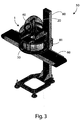
- a system 50 comprising a conveyor belt 60, on which lids 70 to be subjected to examination are provided, and an upright 80, on which a slide 81 is sliding the coupled light emitting diodes on which said detection apparatus 1 is fixed.
- Said system 50 is provided with means, e.g. mechanical or hydraulic means, to vertically move said slide 81 along said upright 80, so as to make said apparatus 1 taking a rest position, wherein said apparatus 1 is in a raised position, and an operative position, wherein said apparatus 1 is in a lowered position, above said lid 70 to be subjected to examination, so that it is lightened, and the image can be detected.
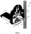
- different parts of lid 70 i.e. central portion 71, circular ribs 72 and edge curl 73.
- Figures 5 - 8 show images taken by camera 40, processed by said procession and control unit (not shown in the figures), that can individuate defects of lid 70 under examination. From said figures, there are observed also detected defects:
- frequencies that can be used can vary also outside visible range, thus being possible also employingradiation beams at infrared and/or ultraviolet frequencies.
Landscapes
- Physics & Mathematics (AREA)
- Health & Medical Sciences (AREA)
- Life Sciences & Earth Sciences (AREA)
- Chemical & Material Sciences (AREA)
- Analytical Chemistry (AREA)
- Biochemistry (AREA)
- General Health & Medical Sciences (AREA)
- General Physics & Mathematics (AREA)
- Immunology (AREA)
- Pathology (AREA)
- Investigating Materials By The Use Of Optical Means Adapted For Particular Applications (AREA)
- Analysing Materials By The Use Of Radiation (AREA)
Description
- The present invention relates to an apparatus for detecting defects of elements to be subjected to examination, particularly metallic lids, system for detection of defects provided with said apparatus and relevant operation method.
- More specifically, the invention relates to an apparatus for detecting lids, particularly metallic lids for tins, cans or other kind of metallic containers, mainly destined to containing food, said apparatus being particularly studied and realised for detecting surface defects such as scratches, contaminations, dings, re-entrance and like, in different portions of the lid.
- The specification will be addressed in the following to detection of metallic lids for tins, but it is well evident that the same must not be considered limited to this specific use.
- As it is well known, different kind of foodstuffs, such as legumes, vegetables, meat, ecc., are preserved within metallic containers or cans. Said cans are generally closed by substantially flat metallic lids, covered by a protection film. Said film is suitable to prevent contact between foodstuffs and lid metallic, so as to prevent that oxidation of metal can contact foodstuff contained within the container.
- It must be taken into consideration that cans are usually subjected to remarkable mechanical stresses. Furthermore, it often occurs that foodstuffs are preserved for a very long time, often even for years.
- It implies that said lids, placed on said tins, must have very strict constructive and qualitative characteristics, in order to prevent that possible mechanical defects, such as surface or edge dings, permit to air entering within the container, so as to destroy products contained therein, or that lid metal oxidations can contact the foodstuff.
- Different system exist for checking metallic lids and like, able to discard defective lids, said systems comprising a conveyor belt, on which said lids to be subjected to examination are transported, a containment frame, preferably provided above said conveyor belt, that can take a not operative position and an operative position, on which a lid to be subjected to examination is placed, a light source, provided inside said containment frame, to lighten the lid. Said systems usually also comprise video means for detection of the lid under examination, connected with said light source and with said detection means, processing image so as to detect defects on said lid.
- A recurrent problem well known to those skilled in the art is that of permitting detection of every kind of defects, and particularly surface scratches and curl dings.
- An apparatus for inspection of lids according to known art is described in European Patent
EP 0729572 B1 , concerning a video detection system, provided with a light emitting diode array for generating a lighting along different wavelengths, with fixing means for said light emitting diode array, so that the latter can lighten a sample or element to be subjected to examination, and suitable power supply means, that can activate said light emitting diodes on the basis of wavelengths, so as to generate a light or lightening from all, or only from part of light emitting diodes having such a wavelength selected between at least a, first wavelength and a second wavelength. Said system is also provided with video-detection means, that can receive light diffused from the element to be subjected to examination. - Said video-detection means also comprise insulation means, substantially concerning filtering means, that can distinguish light received into a first wavelength and a second wavelength. Said filtering means are substantially of the optical type.
- The system described improves reliability of known systems, since it permits lightening lid to be subjected to examination with different wavelengths, at different and consecutive time intervals, by said supply means, which are differentiated on the basis of the wavelength type.
- However, it has been noted that it has different problems when mainly detecting lid scratches and ribs. Furthermore, said system has productivity problems, since number of detections carried out by the system is equal to the number of wavelengths that can be emitted by lightening source and that supply means can select, thus reducing the control speed. It is well evident that such a procedure is long, requiring too much time. Another example of an apparatus for optical inspection is provided in patent document
JPH11295047A - Further solutions for detecting different types of defects use a plurality of cameras. However, in such a case, a remarkable increase of processing time occurs, and in any case, on the basis of empirical analyses, it has been noted that it also this kind of solution is not reliable.
- In view of the above, it is therefore object of the present invention that of providing an apparatus for checking lids that can detect different kind of defects at the same time, without the needing of activating different kind of lightening during different time intervals.
- A further object of the present invention is that of suggesting an apparatus for checking lids, which is compact.
- These and other results are obtained according to the invention by a detection apparatus according to the
claim 1 that can emit radiation beams within a frequency range, so that each radiation beam emitted by suitable lightening means for lightening a lid to be subjected to examination realises an optical path making an incidence angle with respect to the surface of a lid to be subjected to examination which is directly proportional to the relevant emission frequency. - It is therefore specific object of the present invention, an apparatus for detecting defects of elements to be subjected to examination, particularly metallic lids, comprising means for lighting an element to be subjected to examination, an image acquisition unit for acquisition of images, such as a camera or like, able detecting image of said element to be subjected to examination lightened by said lighting means, a unit for processing images acquired by said image acquisition unit, suitable to detect said defects, characterized in that said lighting means emit radiation beams according two or more frequencies included within a range set beforehand, each one of said radiation beams lighting said element to be subjected to examination according to an optical path, individuating an incidence angle with respect to the surface of said element to be subjected to examination included between a grazing minimum incidence angle and a scattering maximum incidence angle, said lighting means being provided so that incidence angle realized by the optical path of each one of said radiation beams emitted by lighting means is directly proportional with respect to the relevant emission frequency.
- Always according to the invention, said grazing minimum incidence angle corresponds to the radiation beam emitted by said lighting means at lower frequency of said set range.
- Still, according to the invention, said lighting means comprise a plurality of light emitting diodes for emission of said radiation beams, said light emitting diodes being provided so that incidence angle of radiation beam optical path emitted by each one of said light emitting diodes is directly proportional with respect to the emission frequency.
- Furthermore, according to the invention, said lighting means comprise a diffuser, having a substantially hemispherical shape, with its concavity faced downward, provided at the top with a hole, through which said image acquisition unit detects image of said element to be subjected to examination, and in that said light emitting diodes of said first lighting means are grouped in a first, a second and a third light emitting diode assembly, said light emitting diode assembly is installed according to a ring arrangement outside said diffuser, so as to grazing lighten said element to be subjected to examination, and it is suitable to emit at a first minimum frequency, preferably within the red field, said second light emitting diode assembly is installed according to a ring arrangement outside said diffuser, so as to lighten said element to be subjected to grazing scattering examination, and it suitable to emit at a second intermediate frequency, preferably within the green field, and said third light emitting diode assembly comprises a first light emitting diode group installed according to a ring arrangement above said diffuser, and a second light emitting diode group, arranged vertically above said diffuser, so as to lighten said element to be subjected to scattering examination, and it is suitable to emit at a third intermediate frequency, preferably within the blue field.
- Always according to the invention, said lighting means further comprise a beam splitter mirror, provided above said diffuser reflecting the radiation beam emitted by said second light emitting diode group on said element to be subjected to examination and permitting detection of image of said element to be subjected to examination by said image acquisition unit.
- Still according to the invention, said apparatus comprises a protection hood, open at the bottom, within which said image acquisition unit and said lighting means are provided, the latter placed under said image acquisition unit.
- Advantageously, according to the invention, said image processing unit can make an image digital filtering according to each one of said two or more frequencies, so as to automatically recognize said defects of each filtered image.
- According to the present invention a system according to the claim 6 is provided for detection of defects on an element to be subjected to examination, particularly metallic lids, comprising a conveyor belt, on which said elements to be subjected to examination are conveyed, an upright, substantially vertical with respect to said conveyor belt, a slide sliding coupled with said upright, and an apparatus for detecting defects of said elements to be subjected to examination, fixed to said slide, so that said apparatus can have a rest position, raised with respect to said conveyor belt, and an operative position, in a lowered mode to be above said element to be subjected to examination, so as to lighten the same and acquiring the image, wherein said apparatus for detecting defects is apparatus as defined in the above.
- According to claim 7 there is provided a method for detecting defects of elements to be subjected to examination, particularly metallic lids, comprising the following steps:
- (a) lighting said element to besubjected to examination;
- (b) acquiring images of said element to be subjected to examination;
- (c) processing images of said element to be subjected to examination acquired during said step (b);
- Always according to the invention, said radiation beam emitted during said step (a) at the lower frequency of said set range corresponds to said incidence angle.
- The present invention will be now described for illustrative but not limitative purposes according to its preferred embodiments, with reference to the figures of the enclosed drawings, wherein:
-
figure 1 shows an apparatus for detecting defects on elements to be subjected to examination, particularly on lids, according to the present invention; -
figure 2 shows a cross-section view of apparatus offigure 1 ; -
figure 3 shows a detection system provided with detection apparatus according tofigure 1 ; -
figure 4 shows a perspective view of a cross-section of a system according tofigure 3 ; and -
figures 5 - 8 show defects detected on a lid by detection apparatus according to the invention. - Same references will be used in the different views to indicate the same or similar parts.
- Making reference to
figures 1 and2 , it is observed anapparatus 1 for detection of defects of metallic lids according to the present invention. Particularly, saidapparatus 1 comprises aprotection hood 20, open at the bottom, within which lighting means 30 for lighting the element to be subjected to examination are provided. Saidapparatus 1 also comprises acolour camera 40, always provided within saidprotection hood 20, above said lighting means. Saidcolour camera 40 is placed so as to take image of surface of element or lid to be subjected to examination, which is lightened by said lighting means 30. - Said lighting means 30 and said
camera 40 are connected to a suitable processing and controlling unit (not shown in the figures), comprising a processor which, besides coordinating lighting and image acquisition operations, also processes images acquired for detection of possible defects on said lids or elements to be subjected to examination. -
Figure 2 particularly shows an embodiment of said lighting means 30, comprising adiffuser 31, having a substantially hemi-spherical shape, provided with ahole 32 at the top. Saiddiffuser 31 is transparent and preferably comprised of Plexiglas. Function of saiddiffuser 31 will be better described in the following. - Said lighting means 30 also comprises a plurality of light emitting diodes (LED) grouped in three different groups, each one able to emit a radiation beam at a relevant frequency. Particularly, in this embodiment, they are provided a minimum frequency f1 within the red domain for
group 33, an intermediate frequency f2 within the green domain forgroup 34, and a maximum frequency f3 within the blue domain forgroup 35. Each one of saidgroups - Particularly, a first group of light emitting
diodes 33, arranged according to a ring or circular arrangement, outside saiddiffuser 31, can grazing lighten the lid to be subjected to examination, i.e. according to a minimum or angle (α) said angle (α) being the angle individuated by grazing incident beam or ray with respect to horizontal plane surface of said lid to be subjected to examination. Said first ligth emittingdiode group 33 emits at the minimum frequency f1, within the red domain, and said radiation beam, should meet a defect (e.g. a scratch or ding) is scattered by the same. This causes a clear or dark detection of said defect bycamera 40, permitting detecting also small scratches on plane surfaces of lids or small defects on curl. - A second group of light emitting
diodes 34, arranged according to a ring or circular arrangement, outside saiddiffuser 31, can grazing diffusion lighten said lid, with incidence angles (α) bigger than incidence angles of said first light emittingdiode group 33. Said second light emittingdiode group 34 is set to emit at said second frequency f2 among the three frequencies provided, i.e. the one within the green domain. Said radiation beam, according to lid surface met (rib, curl, plane portion), is reflected or diffused. Said second LIGHT EMITTINGDIODE group 34 is particularly suitable for detecting defects, such as dings, on ribs of the object under examination. - Finally, third group of light emitting
diodes 35 comprises a first light emitting diode group 35', arranged according to a ring or circular arrangement, in correspondence of the top of saiddiffuser 31, and a second light emittingdiode group 35", placed vertically above thediffuser 31. Radiation beam emitted by said second light emittingdiode group 35" is directed on lid under examination by abeam splitter 36 mirror at an angle of about 45° with respect to the axis perpendicular to the surface of the lid to be subjected to examination, in correspondence of saiddiffuser 31hole 32. Saidbeam splitter 36 mirror permits passage of radiation beam emitted from said second light emittingdiode group 35" through saidcamera 40visualization hole 32.Camera 40 can, thanks to saidbeam splitter 36, detect all radiations diffused/reflected by said lid. Said third light emittingdiode group 35 diffusion lightens said lid with an angle (α) bigger than group of incidence angle of said second light emittingdiode group 34, substantially at about 90°, with a radiation beam substantially directed perpendicular on said lid. Therefore, said radiationbeam is reflected andcamera 40 detects possible defect as in image acquired as dark spot on clear background. Light emitting diodes of saidthird group 35 with a radiation beam at maximum frequency f3 of the three frequencies provided, i.e. the blue one, and can detect both scratches on plane surfaced of the lid, and curl defects. - As it can be observed, the arrangement of the light emitted
diode groups camera 40, at the same time by all light emittingdiode groups - It must be taken into consideration that defect detection by said processing and control unit, electronically filtering images according to the three lighting frequencies, permits easily detecting defects by said processor.
-
Apparatus 1 can also operate placing maximum frequency (blue) radiation beam emission light emitting diodes with a minimum incidence angle or, i.e. grazing, and minimum frequency (red) radiation beam emission LIGHT EMITTING DIODEs with a maximum incidence angle (α), diffusion. However, positioning of red light emitting diodes (minimum frequency) of saidfirst group 33 with grazing minimum incidence angle (α) is the preferred one, since said red light emitting diodes are more luminous and thus require a lower power in order to obtain a sufficient luminosity of diffusions of radiations on a possible defect. - Therefore, said positioning is the preferred one since it permits obtaining an energetic optimization.
- It must be observed that said
diffuser 31 is useful to diffuse light emitted by said light emitting diodes in order to prevent single spot lighting of each light emitting diode. - Making now reference to
figures 3 and4 , it is observed asystem 50 comprising aconveyor belt 60, on which lids 70 to be subjected to examination are provided, and anupright 80, on which aslide 81 is sliding the coupled light emitting diodes on which saiddetection apparatus 1 is fixed. Saidsystem 50 is provided with means, e.g. mechanical or hydraulic means, to vertically move saidslide 81 along said upright 80, so as to make saidapparatus 1 taking a rest position, wherein saidapparatus 1 is in a raised position, and an operative position, wherein saidapparatus 1 is in a lowered position, above saidlid 70 to be subjected to examination, so that it is lightened, and the image can be detected. In this figure, can be noted different parts oflid 70, i.e.central portion 71,circular ribs 72 andedge curl 73. -
Figures 5 - 8 show images taken bycamera 40, processed by said procession and control unit (not shown in the figures), that can individuate defects oflid 70 under examination. From said figures, there are observed also detected defects: -
figure 5 show image ofcamera 40 oflid 70 with defects, without a processing or filtering; -
figure 6 show lid 70, with effect of green and blue radiation beam component effect filtered, and a scratch is observed on plane central portion, passing throughribs 72 and punctiform dings always on planecentral portion 71; -
figure 7 show lid 70 offigure 5 , with effect of red and blue radiation beam component effect filtered, and a scratch and a defect oncurl 73 are observed, the latter not shown infigure 6 ; and -
figure 8 showslid 70 offigure 5 , with effect of red and green radiation beam component effect filtered, and a scratch and a defect are observed oncurl 73, the latter not visible infigure 6 , and better visible infigure 7 . It must be observed that punctiform dings detected with filtering offigure 6 are not detected in this figure. - The above puts into evidence that different lighting at different frequencies can better show different type of defects.
- Obviously, frequencies that can be used can vary also outside visible range, thus being possible also employingradiation beams at infrared and/or ultraviolet frequencies.
Claims (8)
- Apparatus (1) for detecting defects of elements to be subjected to examination, particularly metallic lids (70), comprising
lighting means (30) for lighting an element (70) to be subjected to examination, said lighting means (30) emit radiation beams according two or more frequencies (f1, f2, f3) included within a range set beforehand and comprise a plurality of light emitting diodes (LED) for emission of said radiation beams, an image acquisition unit for acquisition of images, such as a camera (40) or the like, able to detect image of said element to be subjected to examination (70) lightened by said lighting means (30),
a unit for processing images acquired by said image acquisition unit (40), suitable to detect said defects,
each one of said radiation beams lighting said element (70) to be subjected to examination according to an optical path, individuating an incidence angle (α) with respect to the surface of said element to be subjected to examination included between a grazing minimum incidence angle and a scattering maximum incidence angle,
said lighting means (30) comprise a diffuser (31), having a substantially hemispherical shape, with its concavity faced downward, provided at the top with a hole, through which said image acquisition unit detects image of said element (70) to be subjected to examination, and
said light emitting diodes of said lighting means (30) are grouped in a first, a second and a third light emitting diodes assembly (33, 34, 35), said first light emitting diodes assembly (33) is installed according to a ring arrangement outside said diffuser (31), so as to grazing lighten said element (70) to be subjected to examination, and it is suitable to emit at a first minimum frequency (f1) within the red field, said second light emitting diodes assembly (34) is an installation of light emitting diodes according to a ring arrangement outside said diffuser (31), so as to lighten said element (70) to be subjected to grazing scattering examination, and it is suitable to emit at a second intermediate frequency (f3) within the green field and said third light emitting diodes assembly (35) comprises a first light emitting diodes group (35'), wherein the light emitting diodes are installed according to a ring arrangement above said diffuser (31), and a second light emitting diode group (35"), which is arranged vertically above said diffuser (31), so as to lighten said element (70) to be subjected to scattering examination and it is suitable to emit at a third intermediate frequency (f3) within the blue field,
characterized in that said lighting means (30) further comprise a beam splitter mirror (36), provided above said diffuser (31) reflecting the radiation beam emitted by said second light emitting diode group (35") on said element (70) to be subjected to examination and permitting detection of an image of said element (70) to be subjected to examination by said image acquisition unit (40),
wherein the lighting means (30) are provided so that incidence angle (α), realized by the optical path of each one of said radiation beams emitted by lighting means (30) with respect to a horizontal plane surface of said lid to be subjected to examination, is directly proportional with respect to the relevant emission frequency (f1, f2, f3), whereby the first light emitting diodes assembly (33) emits in the red field according to a minimum angle, with respect to a horizontal plane surface of said lid to be subjected to examination, to generate grazing illumination; the second light emitting diodes assembly (34) emits in the green field according to an angle larger than that of the first assembly; the third light emitting diodes assembly (35) emits in the blue field according to an angle larger than that of the second assembly, at about 90°, with a radiation beam directed substantially perpendicular on the lid (70). - Apparatus (1) according to claim 1, characterized in that said grazing minimum incidence angle (α) corresponds to the radiation beam emitted by said lighting means at lower frequency (f1) of said set range.
- Apparatus (1) according to one of the preceding claims, characterized in that said light emitting diodes of said lighting means (30) being provided so that incidence angle (α) of radiation beam optical path emitted by each one of said light emitting diodes is directly proportional with respect to the emission frequency.
- Apparatus (1) according to one of the preceding claims, characterized in that it comprises a protection hood (20), open at the bottom, within which said image acquisition unit (40) and said lighting means (30) are provided, the latter placed under said image acquisition unit (40).
- Apparatus (1) according to one of the preceding claims, characterized in that said image processing unit can make an image digital filtering according to each one of said two or more frequencies (f1, f2, f3), so as to automatically recognize said defects of each filtered image.
- System (50) for detection of defects on element to be subjected to examination, particularly metallic lids (70), comprising
a conveyor belt (60), on which said elements (70) to be subjected to examination are conveyed,
an upright (80), substantially vertical with respect to said conveyor belt (60), a slide (81) which is configured for sliding the coupled light emitting diodes with said upright (80), and
an apparatus for detecting defects of said elements (70) to be subjected to examination, fixed to said slide (81), so that said apparatus can have a rest position, raised with respect to said conveyor belt (60), and an operative position, in a lowered mode to be above said element (70) to be subjected to examination, so as to lighten the same and acquiring the image,
wherein said apparatus for detecting defects is the apparatus (1) as claimed in claims 1 - 5. - Method for detecting defects of elements to be subjected to examination, particularly metallic lids (70), with the apparatus as claimed in one or more of claims 1 to 5, comprising the following steps:(a) lighting said element (70) to be subjected to examination;(b) acquiring images of said element (70) to begsubjected to examination;(c) processing images of said element (70) to be subjected to examination acquired during said step (b);wherein said element (70) to be subjected to examination is lightened during said step (a) by radiation beams according two or more frequencies (f1, f2, f3) included within an interval set beforehand, each one of said radiation beams lightening said element (70) to be subjected to examination according to an optical path individuating an incidence angle (α) with respect to the surface of said element to be subjected to examination included between a grazing minimum incidence angle (α) and a scattering maximum incidence angle (α), incidence angle (α) made up of optical path of each one of said emitted radiation beams being directly proportional to the relevant emission frequency (f1, f2, f3).
- Method according to claim 7, characterized in that radiation beam emitted during said step (a) at the lower frequency (f1) of said set range corresponds to said incidence angle (α).
Applications Claiming Priority (2)
| Application Number | Priority Date | Filing Date | Title |
|---|---|---|---|
| ITRM2009A000567A IT1396723B1 (en) | 2009-11-04 | 2009-11-04 | APPARATUS FOR THE DETECTION OF DEFECTS OF ELEMENTS TO BE EXAMINED, IN PARTICULAR METALLIC COVERS, SYSTEM FOR DETECTING DEFECTS PROVIDED WITH THIS APPARATUS AND RELATIVE FUNCTIONING METHOD. |
| PCT/IT2010/000427 WO2011055397A1 (en) | 2009-11-04 | 2010-10-25 | Apparatus, system and method for detecting defects of metallic lids |
Publications (2)
| Publication Number | Publication Date |
|---|---|
| EP2496933A1 EP2496933A1 (en) | 2012-09-12 |
| EP2496933B1 true EP2496933B1 (en) | 2020-02-19 |
Family
ID=42235580
Family Applications (1)
| Application Number | Title | Priority Date | Filing Date |
|---|---|---|---|
| EP10790679.4A Active EP2496933B1 (en) | 2009-11-04 | 2010-10-25 | Apparatus, system and method for detecting defects of metallic lids |
Country Status (6)
| Country | Link |
|---|---|
| US (1) | US8792094B2 (en) |
| EP (1) | EP2496933B1 (en) |
| KR (1) | KR101844079B1 (en) |
| CN (1) | CN102725625B (en) |
| IT (1) | IT1396723B1 (en) |
| WO (1) | WO2011055397A1 (en) |
Families Citing this family (19)
| Publication number | Priority date | Publication date | Assignee | Title |
|---|---|---|---|---|
| ITMI20121299A1 (en) * | 2012-07-25 | 2014-01-26 | Mondial Marmi S R L | APPARATUS TO ACQUIRE A PLURALITY OF SURFACE IMAGES OF AT LEAST ONE BODY AND RELATIVE METHOD |
| CN103076336A (en) * | 2012-12-28 | 2013-05-01 | 罗炳军 | Object surface quality detector |
| JP2015055569A (en) * | 2013-09-12 | 2015-03-23 | 株式会社Fdkエンジニアリング | Image external appearance inspection device |
| ITBO20150180A1 (en) * | 2015-04-14 | 2016-10-14 | Sacmi Cooperativa Mecc Imola Soc Coop A R L | APPARATUS AND METHOD OF OPTICAL INSPECTION OF OBJECTS, IN PARTICULAR METALLIC LIDS. |
| ITBO20150203A1 (en) * | 2015-04-21 | 2016-10-21 | Sacmi | APPARATUS AND METHOD OF OPTICAL INSPECTION OF PREFORMS. |
| DE102015008409A1 (en) | 2015-07-02 | 2017-01-05 | Eisenmann Se | Installation for optical inspection of surface areas of objects |
| KR20170046918A (en) * | 2015-10-22 | 2017-05-04 | (주)테크윙 | Photographing device for checking goods |
| CN105891218A (en) * | 2016-05-09 | 2016-08-24 | 成都慧信实验设备有限公司 | Device for detecting electronic element surface defect |
| JP6622679B2 (en) * | 2016-10-26 | 2019-12-18 | 川崎重工業株式会社 | Circle scratch inspection device |
| IT201800002782A1 (en) * | 2018-02-16 | 2019-08-16 | Salva Daniel Oscar | SYSTEM OF DIMENSIONAL ANALYSIS OF DEFECTS |
| CN109870463B (en) * | 2019-04-09 | 2020-01-14 | 深圳市阿赛姆电子有限公司 | Electronic chip fault detection device |
| US11282187B2 (en) * | 2019-08-19 | 2022-03-22 | Ricoh Company, Ltd. | Inspection system, inspection apparatus, and method using multiple angle illumination |
| CN112540454B (en) * | 2020-11-11 | 2022-08-02 | 中国航发贵州黎阳航空动力有限公司 | Method for obtaining grain orientation imaging graph |
| CN114264658B (en) * | 2021-03-12 | 2024-01-26 | 青岛昇瑞光电科技有限公司 | LED chip detection device and equipment |
| CN113390890A (en) * | 2021-06-18 | 2021-09-14 | 杭州思元智能科技有限公司 | Electronic component outward appearance detection device based on multi-angle light path illumination |
| DE102021210370A1 (en) | 2021-09-17 | 2023-03-23 | QUISS Qualitäts-Inspektionssysteme und Service GmbH | Apparatus and method for automatically inspecting beverage and food can ends |
| IT202200006344A1 (en) | 2022-03-31 | 2023-10-01 | Antares Vision S P A | OBJECT INSPECTION SYSTEM |
| CN115954291B (en) * | 2023-03-04 | 2023-11-14 | 天合光能(宿迁)光电有限公司 | Crack monitoring system of TOPCON structure photovoltaic cell panel |
| IT202300020598A1 (en) | 2023-10-04 | 2025-04-04 | Antares Vision S P A | IMPROVED SYSTEM FOR OBJECT INSPECTION |
Citations (1)
| Publication number | Priority date | Publication date | Assignee | Title |
|---|---|---|---|---|
| US5461417A (en) * | 1993-02-16 | 1995-10-24 | Northeast Robotics, Inc. | Continuous diffuse illumination method and apparatus |
Family Cites Families (9)
| Publication number | Priority date | Publication date | Assignee | Title |
|---|---|---|---|---|
| CA2064250C (en) * | 1989-08-15 | 2002-04-30 | Don W. Cochran | Engineered video inspection lighting array |
| US5365084A (en) | 1991-02-20 | 1994-11-15 | Pressco Technology, Inc. | Video inspection system employing multiple spectrum LED illumination |
| JPH11295047A (en) * | 1998-04-06 | 1999-10-29 | Omron Corp | Lighting equipment |
| EP1455179A1 (en) * | 2003-03-07 | 2004-09-08 | MV Research Limited | A machine vision inspection system and method |
| JP4139743B2 (en) * | 2003-06-12 | 2008-08-27 | 日本軽金属株式会社 | Apparatus for measuring non-metallic inclusions in aluminum |
| DE102004034160A1 (en) | 2004-07-15 | 2006-02-09 | Byk Gardner Gmbh | Device for studying optical surface properties |
| CN2867100Y (en) * | 2005-07-13 | 2007-02-07 | 王锦峰 | Online light source generator |
| JP2008216180A (en) | 2007-03-07 | 2008-09-18 | Omron Corp | Surface condition inspection method and surface condition inspection apparatus |
| JP2009192544A (en) | 2009-06-01 | 2009-08-27 | Hitachi Chem Co Ltd | Spectroscopic apparatus and total reflection raman spectrum system |
-
2009
- 2009-11-04 IT ITRM2009A000567A patent/IT1396723B1/en active
-
2010
- 2010-10-25 KR KR1020127009330A patent/KR101844079B1/en not_active Expired - Fee Related
- 2010-10-25 US US13/508,038 patent/US8792094B2/en active Active
- 2010-10-25 EP EP10790679.4A patent/EP2496933B1/en active Active
- 2010-10-25 CN CN201080049544.7A patent/CN102725625B/en not_active Expired - Fee Related
- 2010-10-25 WO PCT/IT2010/000427 patent/WO2011055397A1/en not_active Ceased
Patent Citations (1)
| Publication number | Priority date | Publication date | Assignee | Title |
|---|---|---|---|---|
| US5461417A (en) * | 1993-02-16 | 1995-10-24 | Northeast Robotics, Inc. | Continuous diffuse illumination method and apparatus |
Also Published As
| Publication number | Publication date |
|---|---|
| KR20120109473A (en) | 2012-10-08 |
| WO2011055397A4 (en) | 2011-06-30 |
| IT1396723B1 (en) | 2012-12-14 |
| CN102725625A (en) | 2012-10-10 |
| ITRM20090567A1 (en) | 2011-05-05 |
| CN102725625B (en) | 2015-05-06 |
| KR101844079B1 (en) | 2018-05-14 |
| EP2496933A1 (en) | 2012-09-12 |
| US20120268733A1 (en) | 2012-10-25 |
| WO2011055397A1 (en) | 2011-05-12 |
| US8792094B2 (en) | 2014-07-29 |
Similar Documents
| Publication | Publication Date | Title |
|---|---|---|
| US8792094B2 (en) | Apparatus, system and method for detecting defects of metallic lids | |
| US11724286B2 (en) | Method and apparatus for detecting matter | |
| US5884775A (en) | System and method of inspecting peel-bearing potato pieces for defects | |
| EP0387930B1 (en) | Simultaneous double inspection | |
| US11193893B2 (en) | Inspection device with colour lighting | |
| JP6017549B2 (en) | Inspection of empty bottles | |
| US20060037892A1 (en) | Apparatus for optically analyzing products such as fruit having indirect illumination | |
| EP1676124B1 (en) | Inspection device for objects with a spherical surface | |
| JP2006300943A (en) | Inspection system | |
| US6532064B1 (en) | Automatic inspection apparatus and method for simultaneous detection of anomalies in a 3-dimensional translucent object | |
| KR102630458B1 (en) | Apparatus and method for optical inspection of objects, in particular metal lids | |
| AU2004230628A1 (en) | Automated inspection of packaging materials for package integrity | |
| RU2298780C2 (en) | Device for making measurements in liquid product packed in glass containers | |
| JP2003245611A (en) | Food imaging and discharging device | |
| WO2000077499A1 (en) | Method for inspecting of a transparent packaging and apparatus and system to be used therewith | |
| JP4616780B2 (en) | Pesticide residue measuring device | |
| JPH10267854A (en) | Multilayer reflecting background for optical selector | |
| JP2004212079A (en) | Lighting equipment for container inspection |
Legal Events
| Date | Code | Title | Description |
|---|---|---|---|
| PUAI | Public reference made under article 153(3) epc to a published international application that has entered the european phase |
Free format text: ORIGINAL CODE: 0009012 |
|
| 17P | Request for examination filed |
Effective date: 20120326 |
|
| AK | Designated contracting states |
Kind code of ref document: A1 Designated state(s): AL AT BE BG CH CY CZ DE DK EE ES FI FR GB GR HR HU IE IS IT LI LT LU LV MC MK MT NL NO PL PT RO RS SE SI SK SM TR |
|
| DAX | Request for extension of the european patent (deleted) | ||
| STAA | Information on the status of an ep patent application or granted ep patent |
Free format text: STATUS: EXAMINATION IS IN PROGRESS |
|
| 17Q | First examination report despatched |
Effective date: 20171109 |
|
| GRAP | Despatch of communication of intention to grant a patent |
Free format text: ORIGINAL CODE: EPIDOSNIGR1 |
|
| STAA | Information on the status of an ep patent application or granted ep patent |
Free format text: STATUS: GRANT OF PATENT IS INTENDED |
|
| INTG | Intention to grant announced |
Effective date: 20191022 |
|
| GRAS | Grant fee paid |
Free format text: ORIGINAL CODE: EPIDOSNIGR3 |
|
| GRAA | (expected) grant |
Free format text: ORIGINAL CODE: 0009210 |
|
| STAA | Information on the status of an ep patent application or granted ep patent |
Free format text: STATUS: THE PATENT HAS BEEN GRANTED |
|
| AK | Designated contracting states |
Kind code of ref document: B1 Designated state(s): AL AT BE BG CH CY CZ DE DK EE ES FI FR GB GR HR HU IE IS IT LI LT LU LV MC MK MT NL NO PL PT RO RS SE SI SK SM TR |
|
| REG | Reference to a national code |
Ref country code: GB Ref legal event code: FG4D |
|
| REG | Reference to a national code |
Ref country code: CH Ref legal event code: EP |
|
| REG | Reference to a national code |
Ref country code: DE Ref legal event code: R096 Ref document number: 602010063170 Country of ref document: DE |
|
| REG | Reference to a national code |
Ref country code: AT Ref legal event code: REF Ref document number: 1235534 Country of ref document: AT Kind code of ref document: T Effective date: 20200315 |
|
| REG | Reference to a national code |
Ref country code: IE Ref legal event code: FG4D |
|
| REG | Reference to a national code |
Ref country code: NL Ref legal event code: MP Effective date: 20200219 |
|
| PG25 | Lapsed in a contracting state [announced via postgrant information from national office to epo] |
Ref country code: RS Free format text: LAPSE BECAUSE OF FAILURE TO SUBMIT A TRANSLATION OF THE DESCRIPTION OR TO PAY THE FEE WITHIN THE PRESCRIBED TIME-LIMIT Effective date: 20200219 Ref country code: FI Free format text: LAPSE BECAUSE OF FAILURE TO SUBMIT A TRANSLATION OF THE DESCRIPTION OR TO PAY THE FEE WITHIN THE PRESCRIBED TIME-LIMIT Effective date: 20200219 Ref country code: NO Free format text: LAPSE BECAUSE OF FAILURE TO SUBMIT A TRANSLATION OF THE DESCRIPTION OR TO PAY THE FEE WITHIN THE PRESCRIBED TIME-LIMIT Effective date: 20200519 |
|
| REG | Reference to a national code |
Ref country code: LT Ref legal event code: MG4D |
|
| PG25 | Lapsed in a contracting state [announced via postgrant information from national office to epo] |
Ref country code: LV Free format text: LAPSE BECAUSE OF FAILURE TO SUBMIT A TRANSLATION OF THE DESCRIPTION OR TO PAY THE FEE WITHIN THE PRESCRIBED TIME-LIMIT Effective date: 20200219 Ref country code: SE Free format text: LAPSE BECAUSE OF FAILURE TO SUBMIT A TRANSLATION OF THE DESCRIPTION OR TO PAY THE FEE WITHIN THE PRESCRIBED TIME-LIMIT Effective date: 20200219 Ref country code: HR Free format text: LAPSE BECAUSE OF FAILURE TO SUBMIT A TRANSLATION OF THE DESCRIPTION OR TO PAY THE FEE WITHIN THE PRESCRIBED TIME-LIMIT Effective date: 20200219 Ref country code: IS Free format text: LAPSE BECAUSE OF FAILURE TO SUBMIT A TRANSLATION OF THE DESCRIPTION OR TO PAY THE FEE WITHIN THE PRESCRIBED TIME-LIMIT Effective date: 20200619 Ref country code: BG Free format text: LAPSE BECAUSE OF FAILURE TO SUBMIT A TRANSLATION OF THE DESCRIPTION OR TO PAY THE FEE WITHIN THE PRESCRIBED TIME-LIMIT Effective date: 20200519 Ref country code: GR Free format text: LAPSE BECAUSE OF FAILURE TO SUBMIT A TRANSLATION OF THE DESCRIPTION OR TO PAY THE FEE WITHIN THE PRESCRIBED TIME-LIMIT Effective date: 20200520 |
|
| PG25 | Lapsed in a contracting state [announced via postgrant information from national office to epo] |
Ref country code: NL Free format text: LAPSE BECAUSE OF FAILURE TO SUBMIT A TRANSLATION OF THE DESCRIPTION OR TO PAY THE FEE WITHIN THE PRESCRIBED TIME-LIMIT Effective date: 20200219 |
|
| PG25 | Lapsed in a contracting state [announced via postgrant information from national office to epo] |
Ref country code: RO Free format text: LAPSE BECAUSE OF FAILURE TO SUBMIT A TRANSLATION OF THE DESCRIPTION OR TO PAY THE FEE WITHIN THE PRESCRIBED TIME-LIMIT Effective date: 20200219 Ref country code: SK Free format text: LAPSE BECAUSE OF FAILURE TO SUBMIT A TRANSLATION OF THE DESCRIPTION OR TO PAY THE FEE WITHIN THE PRESCRIBED TIME-LIMIT Effective date: 20200219 Ref country code: CZ Free format text: LAPSE BECAUSE OF FAILURE TO SUBMIT A TRANSLATION OF THE DESCRIPTION OR TO PAY THE FEE WITHIN THE PRESCRIBED TIME-LIMIT Effective date: 20200219 Ref country code: PT Free format text: LAPSE BECAUSE OF FAILURE TO SUBMIT A TRANSLATION OF THE DESCRIPTION OR TO PAY THE FEE WITHIN THE PRESCRIBED TIME-LIMIT Effective date: 20200712 Ref country code: DK Free format text: LAPSE BECAUSE OF FAILURE TO SUBMIT A TRANSLATION OF THE DESCRIPTION OR TO PAY THE FEE WITHIN THE PRESCRIBED TIME-LIMIT Effective date: 20200219 Ref country code: ES Free format text: LAPSE BECAUSE OF FAILURE TO SUBMIT A TRANSLATION OF THE DESCRIPTION OR TO PAY THE FEE WITHIN THE PRESCRIBED TIME-LIMIT Effective date: 20200219 Ref country code: LT Free format text: LAPSE BECAUSE OF FAILURE TO SUBMIT A TRANSLATION OF THE DESCRIPTION OR TO PAY THE FEE WITHIN THE PRESCRIBED TIME-LIMIT Effective date: 20200219 Ref country code: SM Free format text: LAPSE BECAUSE OF FAILURE TO SUBMIT A TRANSLATION OF THE DESCRIPTION OR TO PAY THE FEE WITHIN THE PRESCRIBED TIME-LIMIT Effective date: 20200219 Ref country code: EE Free format text: LAPSE BECAUSE OF FAILURE TO SUBMIT A TRANSLATION OF THE DESCRIPTION OR TO PAY THE FEE WITHIN THE PRESCRIBED TIME-LIMIT Effective date: 20200219 |
|
| REG | Reference to a national code |
Ref country code: AT Ref legal event code: MK05 Ref document number: 1235534 Country of ref document: AT Kind code of ref document: T Effective date: 20200219 |
|
| REG | Reference to a national code |
Ref country code: DE Ref legal event code: R097 Ref document number: 602010063170 Country of ref document: DE |
|
| PLBE | No opposition filed within time limit |
Free format text: ORIGINAL CODE: 0009261 |
|
| STAA | Information on the status of an ep patent application or granted ep patent |
Free format text: STATUS: NO OPPOSITION FILED WITHIN TIME LIMIT |
|
| 26N | No opposition filed |
Effective date: 20201120 |
|
| PG25 | Lapsed in a contracting state [announced via postgrant information from national office to epo] |
Ref country code: AT Free format text: LAPSE BECAUSE OF FAILURE TO SUBMIT A TRANSLATION OF THE DESCRIPTION OR TO PAY THE FEE WITHIN THE PRESCRIBED TIME-LIMIT Effective date: 20200219 |
|
| PG25 | Lapsed in a contracting state [announced via postgrant information from national office to epo] |
Ref country code: SI Free format text: LAPSE BECAUSE OF FAILURE TO SUBMIT A TRANSLATION OF THE DESCRIPTION OR TO PAY THE FEE WITHIN THE PRESCRIBED TIME-LIMIT Effective date: 20200219 Ref country code: PL Free format text: LAPSE BECAUSE OF FAILURE TO SUBMIT A TRANSLATION OF THE DESCRIPTION OR TO PAY THE FEE WITHIN THE PRESCRIBED TIME-LIMIT Effective date: 20200219 |
|
| GBPC | Gb: european patent ceased through non-payment of renewal fee |
Effective date: 20201025 |
|
| PG25 | Lapsed in a contracting state [announced via postgrant information from national office to epo] |
Ref country code: MC Free format text: LAPSE BECAUSE OF FAILURE TO SUBMIT A TRANSLATION OF THE DESCRIPTION OR TO PAY THE FEE WITHIN THE PRESCRIBED TIME-LIMIT Effective date: 20200219 Ref country code: LU Free format text: LAPSE BECAUSE OF NON-PAYMENT OF DUE FEES Effective date: 20201025 |
|
| REG | Reference to a national code |
Ref country code: BE Ref legal event code: MM Effective date: 20201031 |
|
| PG25 | Lapsed in a contracting state [announced via postgrant information from national office to epo] |
Ref country code: FR Free format text: LAPSE BECAUSE OF NON-PAYMENT OF DUE FEES Effective date: 20201031 |
|
| PG25 | Lapsed in a contracting state [announced via postgrant information from national office to epo] |
Ref country code: BE Free format text: LAPSE BECAUSE OF NON-PAYMENT OF DUE FEES Effective date: 20201031 Ref country code: GB Free format text: LAPSE BECAUSE OF NON-PAYMENT OF DUE FEES Effective date: 20201025 |
|
| PG25 | Lapsed in a contracting state [announced via postgrant information from national office to epo] |
Ref country code: IE Free format text: LAPSE BECAUSE OF NON-PAYMENT OF DUE FEES Effective date: 20201025 |
|
| PGFP | Annual fee paid to national office [announced via postgrant information from national office to epo] |
Ref country code: IT Payment date: 20210922 Year of fee payment: 12 Ref country code: CH Payment date: 20210921 Year of fee payment: 12 |
|
| PGFP | Annual fee paid to national office [announced via postgrant information from national office to epo] |
Ref country code: DE Payment date: 20210921 Year of fee payment: 12 |
|
| PG25 | Lapsed in a contracting state [announced via postgrant information from national office to epo] |
Ref country code: TR Free format text: LAPSE BECAUSE OF FAILURE TO SUBMIT A TRANSLATION OF THE DESCRIPTION OR TO PAY THE FEE WITHIN THE PRESCRIBED TIME-LIMIT Effective date: 20200219 Ref country code: MT Free format text: LAPSE BECAUSE OF FAILURE TO SUBMIT A TRANSLATION OF THE DESCRIPTION OR TO PAY THE FEE WITHIN THE PRESCRIBED TIME-LIMIT Effective date: 20200219 Ref country code: CY Free format text: LAPSE BECAUSE OF FAILURE TO SUBMIT A TRANSLATION OF THE DESCRIPTION OR TO PAY THE FEE WITHIN THE PRESCRIBED TIME-LIMIT Effective date: 20200219 |
|
| PG25 | Lapsed in a contracting state [announced via postgrant information from national office to epo] |
Ref country code: MK Free format text: LAPSE BECAUSE OF FAILURE TO SUBMIT A TRANSLATION OF THE DESCRIPTION OR TO PAY THE FEE WITHIN THE PRESCRIBED TIME-LIMIT Effective date: 20200219 Ref country code: AL Free format text: LAPSE BECAUSE OF FAILURE TO SUBMIT A TRANSLATION OF THE DESCRIPTION OR TO PAY THE FEE WITHIN THE PRESCRIBED TIME-LIMIT Effective date: 20200219 |
|
| REG | Reference to a national code |
Ref country code: DE Ref legal event code: R119 Ref document number: 602010063170 Country of ref document: DE |
|
| REG | Reference to a national code |
Ref country code: CH Ref legal event code: PL |
|
| PG25 | Lapsed in a contracting state [announced via postgrant information from national office to epo] |
Ref country code: LI Free format text: LAPSE BECAUSE OF NON-PAYMENT OF DUE FEES Effective date: 20221031 Ref country code: DE Free format text: LAPSE BECAUSE OF NON-PAYMENT OF DUE FEES Effective date: 20230503 Ref country code: CH Free format text: LAPSE BECAUSE OF NON-PAYMENT OF DUE FEES Effective date: 20221031 |
|
| PG25 | Lapsed in a contracting state [announced via postgrant information from national office to epo] |
Ref country code: IT Free format text: LAPSE BECAUSE OF NON-PAYMENT OF DUE FEES Effective date: 20221025 |