EP2496493B1 - Support unit - Google Patents
Support unit Download PDFInfo
- Publication number
- EP2496493B1 EP2496493B1 EP10779683.1A EP10779683A EP2496493B1 EP 2496493 B1 EP2496493 B1 EP 2496493B1 EP 10779683 A EP10779683 A EP 10779683A EP 2496493 B1 EP2496493 B1 EP 2496493B1
- Authority
- EP
- European Patent Office
- Prior art keywords
- support unit
- slit
- drain tap
- box
- unit according
- Prior art date
- Legal status (The legal status is an assumption and is not a legal conclusion. Google has not performed a legal analysis and makes no representation as to the accuracy of the status listed.)
- Not-in-force
Links
Images


Classifications
-
- B—PERFORMING OPERATIONS; TRANSPORTING
- B65—CONVEYING; PACKING; STORING; HANDLING THIN OR FILAMENTARY MATERIAL
- B65D—CONTAINERS FOR STORAGE OR TRANSPORT OF ARTICLES OR MATERIALS, e.g. BAGS, BARRELS, BOTTLES, BOXES, CANS, CARTONS, CRATES, DRUMS, JARS, TANKS, HOPPERS, FORWARDING CONTAINERS; ACCESSORIES, CLOSURES, OR FITTINGS THEREFOR; PACKAGING ELEMENTS; PACKAGES
- B65D77/00—Packages formed by enclosing articles or materials in preformed containers, e.g. boxes, cartons, sacks or bags
- B65D77/04—Articles or materials enclosed in two or more containers disposed one within another
- B65D77/06—Liquids or semi-liquids or other materials or articles enclosed in flexible containers disposed within rigid containers
- B65D77/062—Flexible containers disposed within polygonal containers formed by folding a carton blank
- B65D77/065—Spouts, pouring necks or discharging tubes fixed to or integral with the flexible container
- B65D77/067—Spouts, pouring necks or discharging tubes fixed to or integral with the flexible container combined with a valve, a tap or a piercer
-
- B—PERFORMING OPERATIONS; TRANSPORTING
- B67—OPENING, CLOSING OR CLEANING BOTTLES, JARS OR SIMILAR CONTAINERS; LIQUID HANDLING
- B67D—DISPENSING, DELIVERING OR TRANSFERRING LIQUIDS, NOT OTHERWISE PROVIDED FOR
- B67D3/00—Apparatus or devices for controlling flow of liquids under gravity from storage containers for dispensing purposes
- B67D3/0058—Details
- B67D3/008—Supports
-
- B—PERFORMING OPERATIONS; TRANSPORTING
- B65—CONVEYING; PACKING; STORING; HANDLING THIN OR FILAMENTARY MATERIAL
- B65D—CONTAINERS FOR STORAGE OR TRANSPORT OF ARTICLES OR MATERIALS, e.g. BAGS, BARRELS, BOTTLES, BOXES, CANS, CARTONS, CRATES, DRUMS, JARS, TANKS, HOPPERS, FORWARDING CONTAINERS; ACCESSORIES, CLOSURES, OR FITTINGS THEREFOR; PACKAGING ELEMENTS; PACKAGES
- B65D2313/00—Connecting or fastening means
-
- Y—GENERAL TAGGING OF NEW TECHNOLOGICAL DEVELOPMENTS; GENERAL TAGGING OF CROSS-SECTIONAL TECHNOLOGIES SPANNING OVER SEVERAL SECTIONS OF THE IPC; TECHNICAL SUBJECTS COVERED BY FORMER USPC CROSS-REFERENCE ART COLLECTIONS [XRACs] AND DIGESTS
- Y10—TECHNICAL SUBJECTS COVERED BY FORMER USPC
- Y10T—TECHNICAL SUBJECTS COVERED BY FORMER US CLASSIFICATION
- Y10T29/00—Metal working
- Y10T29/49—Method of mechanical manufacture
- Y10T29/49826—Assembling or joining
Definitions
- the present invention relates to a support unit for supporting a drain tap in a flexible bag located in a bag in box (BIB) liquid dispenser.
- the invention relates also to the use of the support unit.
- Liquid dispensers such as e.g. cardboard boxes for wine with a drain tap often referred to as BIB (bag in box) are used in a still increasing extent.
- BIB bag in box
- these kinds of containers have many positive characteristics, including that the liquid, e.g. the wine, can be drained off in portions without oxygen supply, since the wine is kept in an airtight plastic bag inside the outer container or box, which is mostly manufactured from cardboard
- the tap valve When the wine or other beverage is to be consumed the tap valve is lead though an opening in the in the box.
- the box has normally been prepared for this opening by weakened lines for tearing the cardboard open to allow the tubular shaped drain tap to pass through the wall of the box.
- the drain tap When the drain tap is lead through the wall of the box it is only supported by the cardboard, which may be relatively thin and soft. This weak support has the effect that the tap valve may difficult to operate in particular with one hand, which is often necessary when the wine or other beverage has to be drained into a glass by a person.
- European patent application EP 0884269 discloses a device for dispensing liquids from bag-in-boxes provided with a drain tap, which comprises a base for accommodating and supporting at least one bag-in-box.
- the device further comprises two half-circular retention means which are meant to detachably engage a portion of the drain tap in order to rigidly couple the bag-in-box to the seating and supporting base and to support the drain tap in the bag-in-box.
- US 3696969 disclosing a beverage dispensing system describes an embodiment where a reinforcing collar is inserted to support the tap.
- the reinforcing collar is made from a flat piece of plastic or metal with a slit to engage with the tap.
- the known supporting devices may function very well as such, they are either relatively complicated to manufacture and use or they are difficult to mount and optionally remove for reuse due to poor gripping properties.
- the latter is particularly true for the flat type of support which, moreover, may suffer from the drawback that they are easy to break, in particular if they are made from a plastic material.
- the object of the present invention is to provide a support unit for supporting a drain tap in a bag in a bag in box dispensing system, which support unit is easy and simple to use and mount on a drain tap from a bag in box, and provides a good grip for mounting and removing the support unit.
- an object of the present invention is to provide a support unit for supporting a drain tap in a bag in a bag in box dispensing system, which support unit has an excellent strength and durability, and can be reused several times.
- the invention relates to a support unit for supporting a drain tap in a flexible bag located in a bag in box (BIB) liquid dispenser, wherein the support unit comprises a plate piece having at least a substantially planar area with a least one surface adapted to abut the outer surface of the box and the support unit further comprise a slit to receive the drain tap when lead through the wall of the box and form a supporting collar around the drain tap where the plate piece area next to the slit is tapering towards the opening of the slit thereby forming two tapering areas on each side of the slit, characterised in that the plate piece comprises a convex area located between the outer edge of the support unit and the U-shaped part surrounding the slit.
- the support unit comprises a plate piece having at least a substantially planar area with a least one surface adapted to abut the outer surface of the box and the support unit further comprise a slit to receive the drain tap when lead through the wall of the box and form a supporting collar around the drain tap where the plate piece
- the support unit is particularly suitable for supporting the drain tap mounted on a flexible plastic bag in a box, which drain tap is equipped with a flange to engage with and press against the wall of the box.
- the drain tap on a bag in box dispensing device is substantially tubular shaped and located in the lower part of the bag in box to allow emptying of the bag by the influence of gravity.
- the drain tap comprises a valve preferably a check-valve.
- the support unit according to the invention is equipped with a slit to engage with the drain tap and, moreover, comprises an area with a substantially flat side which can abut the outer surface of the box.
- the opposite side of the support unit is adapted to abut with the side of the flange on the drain tap that faces the outer surface of the box.
- the support unit provides a tension between the flange and the outer surface of the box which again results in an excellent support of the drain tap where a least a part of the support unit forms a supporting collar around the drain tap.
- the size of the slit is selected to fit with the size of regular tubular drain tap. Typically, the width of the slit is in the range of 1 to 5 cm.
- the thickness of the support unit is selected to fit between the outer wall of the box and the flange of the drain tap, preferably the thickness is in the range of 1 to 5 mm
- the slit of the support unit is adapted engage with the drain tap by the action of friction and thereby provide a support of the drain tap.
- the plate area next to the slit is tapering towards the opening of the slit thereby forming two tapering areas or zones on each side of the slit.
- the plate area is preferably tapering symmetrical on both sides of the slit thereby forming two tapering areas which may be asymmetrical on each side of the slit.
- the tapering facilitates the mounting of the support unit on the drain tap and also serves to reduce the material used for producing the support unit.
- the support unit may have any desired shape it is preferred that at least a part of the outer edge of the support unit is curved.
- a support unit with curved edge may require less material for production and still have sufficient strength.
- a curved edge also improves the grip on the support unit when it is removed from the bag in box liquid dispenser.
- the support unit has an approximately circular shaped edge.
- a circular shape optimizes the material consumption and at the same time provides good strength to the support unit.
- the average diameter of the support unit is preferably in the range of 5 to 15 cm.
- the U-shaped slit is preferably located in the plate in such a way that the centre of the tubular drain tap will also constitute the centre of the circle formed by the outer edge of the support unit. In this way the drain tap mounted with the support unit will have an esthetic and harmonic appearance.
- the support unit comprises a convex area.
- the convex area forming a bulge in the support unit also improves the gripping properties of the support unit.
- at least two advantages are achieved, namely, a support unit for bag in box liquid dispenser, which support unit has improved strength and is easier to mount and remove due to better gripping properties.
- the slit has a rounded part adapted to engage with the drain tap.
- the slit is U-shaped, which provides an excellent fit for the tubular shaped drain tap.
- the support unit For the purpose of achieving a good support of the drain tap it is desirable that at least a part of the area with a substantially flat surface surrounds the slit.
- Such embodiments allows the support unit to engage with the outer wall of the box and a flange on the drain tap and provide a tension between the outer surface of the wall and the flange whereby and excellent support of the drain tap is achieved.
- the slit of the support unit is adapted to provide friction between the engaging surfaces of the support unit and the drain tap. This friction will maintain the support unit on the drain tap and allows the support unit to support the drain tap.
- At least a part of the area with a substantially flat surface is U-shaped and surrounds the U-shaped slit to obtain a good engagement with the tubular shaped drain tap.
- the convex area extends around the slit. In this manner the strength of the support unit is improved significantly.
- the convex area extends around at least a part of the area with a substantially flat surface and the slit. This embodiment provides good strength in combination with good supporting properties.
- the periphery of the support unit is adapted to abut the outer surface of the box.
- the periphery of the support has a flat surface adapted to abut the outer surface of the box to improve the support of the drain tap.
- the support unit has a substantially circular periphery.
- a substantially circular periphery facilitates the placing of the support unit on the drain tap as the "corner free" support unit is easy to place on the outer surface of the box.
- the invention also comprises an embodiment where at least a part of the convex area comprises supporting ridges.
- One or more ridges in the convex area significantly increase the strength and the rigidity of the support unit.
- the support unit may be made from several types of material, it is preferred that the support unit is made from a rigid or semi-rigid material selected from plastic, aluminium and stainless steel.
- plastic it may be ABS, polyethylene, polystyrene, etc.
- the support unit may be manufactured in various colours and shapes to fit with drain taps of various bag in box (BIB) liquid dispensers.
- the invention also relates to the use of a support unit as described above for supporting a drain tap in a flexible bag located in a bag in box (BIB) liquid dispenser.
- a support unit as described above for supporting a drain tap in a flexible bag located in a bag in box (BIB) liquid dispenser.
- the use includes embodiments where the surface of the support unit is equipped with a print or logo.
- Such use may be a commercial and marketing use where the support unit may have a company name and/or logo printed on the surface and optionally delivered with a bag in box for beverage dispensing.
- Figure 1 shows an embodiment of a support unit 1 that is not part of the invention.
- the support unit 1 comprises a planar plate piece 2 having a slit 3 to receive a drain tap from a bag in box liquid dispenser.
- the slit 3 is U-shaped as the U-shape allows the support unit 1 to fit with a tubular shaped drain tap and optionally provide friction between the engaging surface of the drain tap and the U-shaped slit.
- the plate piece 2 constituting the support unit 1 has a thickness 4 which is adapted to fit between a flange on the drain tap and the outer surface of the wall of a bag in box.
- the plate piece 2 is tapering towards the opening of the slit 3 thereby forming two tapering areas or zones 5a and 5b.
- the two tapering zones 5a and 5b are asymmetrical and mutual reversed.
- the tapering zones 5a and 5b facilitates the mounting of the support unit on a drain tap from a bag in box liquid dispenser.
- FIG. 2 shows an alternative embodiment of the support unit 1 that is not part of the invention.
- the planar plate piece 2 has a substantially circular outer edge 6 except from the area of the slit 3. Due to the circular shape of the support unit 1 each of the tapering zones 5a and 5b have a curved edge which is part of the outer edge 6.
- FIG 3 a support unit 1 that is not part of the invention having a convex area 7.
- the convex area 7 is formed in the plate piece 2.
- a substantially planar U-shaped part 8 surrounds the U-shaped slit 3.
- the U-shaped part 8 is intended to be located between the flange on a drain tap and the outer wall of a bag in box liquid dispenser.
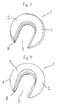
- Figure 4 shows a support unit 1 having a convex area 7 according to the invention.
- the convex area 7 is formed in the plate piece 2 and has a more gradual transition from the outer edge 6 than the convex area 7 of the embodiment shown in figure 3 .
- a substantially planar U-shaped part 8 surrounds the U-shaped slit 3. The U-shaped part 8 is intended to be located between the flange on a drain tap and the outer wall of a bag in box liquid dispenser.
- Figure 5 shows the support unit 1 of figure 4 seen from the back side, i.e. the side intended for facing the outer wall of a bag in box liquid dispenser.
- the convex area 7 is located between the outer edge 6 and the U-shaped part 8 surrounding the slit 3.
- the U-shaped part 8 and the outer edge 6 have a flat surface 9 for abutment with the outer wall of a bag in box liquid dispenser.
- Figure 6 shows a support unit 1 corresponding to the support unit shown in figure 5 where the convex area 7 is equipped with ridges 10a, 10b and 10c.
- the ridges 10a, 10b and 10c improve the strength of the support unit 1.
- FIG. 7 shows a part of a cross-section of a bag in box liquid dispenser 20.
- the bag in box liquid dispenser 20 comprises a wall 21 of cardboard.
- the liquid dispenser 20 contains a bag 22 having a drain tap 23 with a flange 24 attached at the lower part.
- the drain tap 23 is lead through an opening 25 in the wall 21 in such a way that the flange 24 abuts the wall 21 to support the drain tap 23.
- the cardboard wall 21 provides a rather weak support for the drain tap 23.
- FIG 8 shows the same cross-section as in figure 7 .
- the drain tap 23 has now been mounted with a support unit 1 corresponding to the support unit 1 described in figure 4 and figure 5 .
- the U-shaped part 8 of the support unit 1 is inserted between the wall 21 of the bag in box liquid dispenser 20 and the flange 24 of the drain tap 23, whereby the support unit 1 provides an excellent support of the drain tap 23.
- Figure 9 shows a bag in box liquid dispenser 20 mounted with a support unit 1 on the drain tap 23. A part of the support unit 1 is inserted between the wall 21 of the box and the flange 24 of the drain tap 23.
- the cardboard wall 21 has an area 25 through which the drain tap 23 is lead.
- the area 25 is weakened due to the tearing to allow the drain tap 23 to pass through the cardboard wall 21 in this area and may not have sufficient strength to support the drain tap 23 without the assistance of the support unit 1.
- the present invention provides a highly advantageously solution for supporting the drain tap in a bag in box (BIB) liquid dispenser.
- the support unit according to the invention is easy and convenient to use and provides and excellent support for the drain tap in a bag in box liquid dispenser.
Description
- The present invention relates to a support unit for supporting a drain tap in a flexible bag located in a bag in box (BIB) liquid dispenser. The invention relates also to the use of the support unit.
- Liquid dispensers such as e.g. cardboard boxes for wine with a drain tap often referred to as BIB (bag in box) are used in a still increasing extent. This results from the fact that these kinds of containers have many positive characteristics, including that the liquid, e.g. the wine, can be drained off in portions without oxygen supply, since the wine is kept in an airtight plastic bag inside the outer container or box, which is mostly manufactured from cardboard
- The fact that no oxygen is added to the liquid, which is being drained off means that this form of packaging is appropriate for consumers, who only want a single glass of wine for the dinner. Traditional wine bottles of glass are not appropriate for such a pattern of use, as the quality of the wine quickly changes, when the wine bottle is opened. By draining wine off from an airtight plastic bag with a drain tap in a cardboard box the wine will keep its quality for a long time, which is obviously an advantage, if only a single glass or a few glasses of wine are drained off each day.
- It has been found, however, that there are some drawbacks connected to the handling of liquid dispensers in the shape of e.g. bag in cardboard boxes with a drain tap.
- When the wine or other beverage is to be consumed the tap valve is lead though an opening in the in the box. The box has normally been prepared for this opening by weakened lines for tearing the cardboard open to allow the tubular shaped drain tap to pass through the wall of the box. When the drain tap is lead through the wall of the box it is only supported by the cardboard, which may be relatively thin and soft. This weak support has the effect that the tap valve may difficult to operate in particular with one hand, which is often necessary when the wine or other beverage has to be drained into a glass by a person.
- Several attempts to solve this problem have been made. European patent application
EP 0884269 discloses a device for dispensing liquids from bag-in-boxes provided with a drain tap, which comprises a base for accommodating and supporting at least one bag-in-box. The device further comprises two half-circular retention means which are meant to detachably engage a portion of the drain tap in order to rigidly couple the bag-in-box to the seating and supporting base and to support the drain tap in the bag-in-box.. -
US 3696969 disclosing a beverage dispensing system describes an embodiment where a reinforcing collar is inserted to support the tap. The reinforcing collar is made from a flat piece of plastic or metal with a slit to engage with the tap. -
US 2007/0012722 discloses another type of support unit. - Although the known supporting devices may function very well as such, they are either relatively complicated to manufacture and use or they are difficult to mount and optionally remove for reuse due to poor gripping properties. The latter is particularly true for the flat type of support which, moreover, may suffer from the drawback that they are easy to break, in particular if they are made from a plastic material.
- Consequently, the object of the present invention is to provide a support unit for supporting a drain tap in a bag in a bag in box dispensing system, which support unit is easy and simple to use and mount on a drain tap from a bag in box, and provides a good grip for mounting and removing the support unit.
- Moreover, an object of the present invention is to provide a support unit for supporting a drain tap in a bag in a bag in box dispensing system, which support unit has an excellent strength and durability, and can be reused several times.
- Thus, in a first aspect the invention relates to a support unit for supporting a drain tap in a flexible bag located in a bag in box (BIB) liquid dispenser, wherein the support unit comprises a plate piece having at least a substantially planar area with a least one surface adapted to abut the outer surface of the box and the support unit further comprise a slit to receive the drain tap when lead through the wall of the box and form a supporting collar around the drain tap where the plate piece area next to the slit is tapering towards the opening of the slit thereby forming two tapering areas on each side of the slit, characterised in that the plate piece comprises a convex area located between the outer edge of the support unit and the U-shaped part surrounding the slit.
- The support unit is particularly suitable for supporting the drain tap mounted on a flexible plastic bag in a box, which drain tap is equipped with a flange to engage with and press against the wall of the box. Normally, the drain tap on a bag in box dispensing device is substantially tubular shaped and located in the lower part of the bag in box to allow emptying of the bag by the influence of gravity. The drain tap comprises a valve preferably a check-valve.
- The support unit according to the invention is equipped with a slit to engage with the drain tap and, moreover, comprises an area with a substantially flat side which can abut the outer surface of the box. The opposite side of the support unit is adapted to abut with the side of the flange on the drain tap that faces the outer surface of the box. In this manner the support unit provides a tension between the flange and the outer surface of the box which again results in an excellent support of the drain tap where a least a part of the support unit forms a supporting collar around the drain tap. The size of the slit is selected to fit with the size of regular tubular drain tap. Typically, the width of the slit is in the range of 1 to 5 cm. Moreover, the thickness of the support unit is selected to fit between the outer wall of the box and the flange of the drain tap, preferably the thickness is in the range of 1 to 5 mm
- If the drain tap has no flange the slit of the support unit is adapted engage with the drain tap by the action of friction and thereby provide a support of the drain tap.
- An advantage of the support unit is that the plate area next to the slit is tapering towards the opening of the slit thereby forming two tapering areas or zones on each side of the slit. The plate area is preferably tapering symmetrical on both sides of the slit thereby forming two tapering areas which may be asymmetrical on each side of the slit. The tapering facilitates the mounting of the support unit on the drain tap and also serves to reduce the material used for producing the support unit.
- Although the support unit may have any desired shape it is preferred that at least a part of the outer edge of the support unit is curved. A support unit with curved edge may require less material for production and still have sufficient strength. A curved edge also improves the grip on the support unit when it is removed from the bag in box liquid dispenser. In an embodiment the support unit has an approximately circular shaped edge. A circular shape optimizes the material consumption and at the same time provides good strength to the support unit. When the support unit has a circular shape the average diameter of the support unit is preferably in the range of 5 to 15 cm.
- When the support unit has a substantially circular shape, the U-shaped slit is preferably located in the plate in such a way that the centre of the tubular drain tap will also constitute the centre of the circle formed by the outer edge of the support unit. In this way the drain tap mounted with the support unit will have an esthetic and harmonic appearance.
- To improve the strength of the support unit, the support unit comprises a convex area. The convex area forming a bulge in the support unit also improves the gripping properties of the support unit. In this way at least two advantages are achieved, namely, a support unit for bag in box liquid dispenser, which support unit has improved strength and is easier to mount and remove due to better gripping properties.
- To obtain the best possible properties of the support unit the slit has a rounded part adapted to engage with the drain tap. Preferably the slit is U-shaped, which provides an excellent fit for the tubular shaped drain tap.
- For the purpose of achieving a good support of the drain tap it is desirable that at least a part of the area with a substantially flat surface surrounds the slit. Such embodiments allows the support unit to engage with the outer wall of the box and a flange on the drain tap and provide a tension between the outer surface of the wall and the flange whereby and excellent support of the drain tap is achieved.
- If the drain tap has no flange, the slit of the support unit is adapted to provide friction between the engaging surfaces of the support unit and the drain tap. This friction will maintain the support unit on the drain tap and allows the support unit to support the drain tap.
- To improve the properties of the support unit it is preferred that at least a part of the area with a substantially flat surface is U-shaped and surrounds the U-shaped slit to obtain a good engagement with the tubular shaped drain tap.
- In an embodiment of the support unit according to the invention the convex area extends around the slit. In this manner the strength of the support unit is improved significantly. In a preferred embodiment the convex area extends around at least a part of the area with a substantially flat surface and the slit. This embodiment provides good strength in combination with good supporting properties.
- For the purpose of further improving the properties of the support unit the periphery of the support unit is adapted to abut the outer surface of the box. Thus, the periphery of the support has a flat surface adapted to abut the outer surface of the box to improve the support of the drain tap.
- In a preferred embodiment the support unit has a substantially circular periphery. A substantially circular periphery facilitates the placing of the support unit on the drain tap as the "corner free" support unit is easy to place on the outer surface of the box.
- To further improve the strength of the support unit the invention also comprises an embodiment where at least a part of the convex area comprises supporting ridges. One or more ridges in the convex area significantly increase the strength and the rigidity of the support unit.
- Although the support unit may be made from several types of material, it is preferred that the support unit is made from a rigid or semi-rigid material selected from plastic, aluminium and stainless steel. When the support unit is made from plastic it may be ABS, polyethylene, polystyrene, etc. The support unit may be manufactured in various colours and shapes to fit with drain taps of various bag in box (BIB) liquid dispensers.
- The invention also relates to the use of a support unit as described above for supporting a drain tap in a flexible bag located in a bag in box (BIB) liquid dispenser.
- The use includes embodiments where the surface of the support unit is equipped with a print or logo. Such use may be a commercial and marketing use where the support unit may have a company name and/or logo printed on the surface and optionally delivered with a bag in box for beverage dispensing.
- The invention will now be described in further details with reference to drawings where,
-
Fig. 1 shows an embodiment of a support unit that is not part of the invention, -
Fig. 2 shows a different embodiment of a support unit that is not part of the invention, -
Fig. 3 shows an embodiment of a support unit with a convex area that is not part of the invention, -
Fig. 4 shows an embodiment of a support unit with a convex area according to the invention, -
Fig. 5 shows an embodiment of a support unit infig. 4 seen from the other side, -
Fig. 6 shows an embodiment of a support unit with ridges according to an embodiment of the invention, -
Fig. 7 shows a cross-section of a bag in box with drain tap, -
Fig 8 shows the cross- section offig. 7 with a support unit according to the invention mounted on the drain tap, -
Fig. 9 shows a bag in box unit with a support unit according to the invention mounted on the drain tap. - In the following the support unit according to the invention will be described with reference to some preferred embodiments. The reference numbers used will be the same for the same parts and, consequently, refer to the same parts of the support units shown in the drawings.
-
Figure 1 shows an embodiment of asupport unit 1 that is not part of the invention. Thesupport unit 1 comprises aplanar plate piece 2 having aslit 3 to receive a drain tap from a bag in box liquid dispenser. Theslit 3 is U-shaped as the U-shape allows thesupport unit 1 to fit with a tubular shaped drain tap and optionally provide friction between the engaging surface of the drain tap and the U-shaped slit. - The
plate piece 2 constituting thesupport unit 1 has athickness 4 which is adapted to fit between a flange on the drain tap and the outer surface of the wall of a bag in box. Theplate piece 2 is tapering towards the opening of theslit 3 thereby forming two tapering areas orzones tapering zones tapering zones -
Figure 2 shows an alternative embodiment of thesupport unit 1 that is not part of the invention. Theplanar plate piece 2 has a substantially circularouter edge 6 except from the area of theslit 3. Due to the circular shape of thesupport unit 1 each of thetapering zones outer edge 6. - In
figure 3 is seen asupport unit 1 that is not part of the invention having aconvex area 7. Theconvex area 7 is formed in theplate piece 2. A substantially planarU-shaped part 8 surrounds theU-shaped slit 3. TheU-shaped part 8 is intended to be located between the flange on a drain tap and the outer wall of a bag in box liquid dispenser. -
Figure 4 shows asupport unit 1 having aconvex area 7 according to the invention. Theconvex area 7 is formed in theplate piece 2 and has a more gradual transition from theouter edge 6 than theconvex area 7 of the embodiment shown infigure 3 . A substantially planarU-shaped part 8 surrounds theU-shaped slit 3. TheU-shaped part 8 is intended to be located between the flange on a drain tap and the outer wall of a bag in box liquid dispenser. -
Figure 5 shows thesupport unit 1 offigure 4 seen from the back side, i.e. the side intended for facing the outer wall of a bag in box liquid dispenser. Theconvex area 7 is located between theouter edge 6 and theU-shaped part 8 surrounding theslit 3. TheU-shaped part 8 and theouter edge 6 have aflat surface 9 for abutment with the outer wall of a bag in box liquid dispenser. -
Figure 6 shows asupport unit 1 corresponding to the support unit shown infigure 5 where theconvex area 7 is equipped withridges ridges support unit 1. -
Figure 7 shows a part of a cross-section of a bag inbox liquid dispenser 20. The bag inbox liquid dispenser 20 comprises awall 21 of cardboard. Theliquid dispenser 20 contains abag 22 having adrain tap 23 with aflange 24 attached at the lower part. Thedrain tap 23 is lead through anopening 25 in thewall 21 in such a way that theflange 24 abuts thewall 21 to support thedrain tap 23. However, thecardboard wall 21 provides a rather weak support for thedrain tap 23. -
Figure 8 shows the same cross-section as infigure 7 . Thedrain tap 23 has now been mounted with asupport unit 1 corresponding to thesupport unit 1 described infigure 4 andfigure 5 . As it can be seen theU-shaped part 8 of thesupport unit 1 is inserted between thewall 21 of the bag inbox liquid dispenser 20 and theflange 24 of thedrain tap 23, whereby thesupport unit 1 provides an excellent support of thedrain tap 23. -
Figure 9 shows a bag inbox liquid dispenser 20 mounted with asupport unit 1 on thedrain tap 23. A part of thesupport unit 1 is inserted between thewall 21 of the box and theflange 24 of thedrain tap 23. Thecardboard wall 21 has anarea 25 through which thedrain tap 23 is lead. - The
area 25 is weakened due to the tearing to allow thedrain tap 23 to pass through thecardboard wall 21 in this area and may not have sufficient strength to support thedrain tap 23 without the assistance of thesupport unit 1. - As it can be understood the present invention provides a highly advantageously solution for supporting the drain tap in a bag in box (BIB) liquid dispenser. The support unit according to the invention is easy and convenient to use and provides and excellent support for the drain tap in a bag in box liquid dispenser. Although the invention has been described with reference to only a few embodiments it is to be understood that the invention comprises several other embodiments, which are all within the scope of the present invention as set forth in the appended claims.
Claims (13)
- A support unit (1) for supporting a drain tap in a flexible bag located in a bag in box (BIB) liquid dispenser, wherein the support unit (1) comprises a plate piece (2) having at least a substantially planar area with a least one surface adapted to abut the outer surface of the box and the support unit (1) further comprises a U-shaped slit (3) to receive the drain tap when lead through the wall of the box and form a supporting collar around the drain tap where the plate piece area next to the slit is tapering towards the opening of the slit thereby forming two tapering areas (5a, 5b) on each side of the slit, characterised in that the plate piece (2) comprises a convex area located between the outer edge (6) of the support unit and the U-shaped part (3) surrounding the slit (3).
- A support unit according to claim 1, wherein at least a part of the outer edge (6) of the support unit is curved.
- A support unit according to claim 1, wherein the slit (3) has a rounded part adapted to engage with the drain tap.
- A support unit according to claim 1, wherein at least a part of the area with a substantially flat surface surrounds the slit(3)
- A support unit according to claim 1, wherein at least a part of the area with a substantially flat surface is U-shaped.
- A support unit according to claim 1, wherein the convex area extends around the slit (3).
- A support unit according to claim 1, wherein the convex area extends around at least a part of the area with a substantially flat surface and the slit (3).
- A support unit according to claim 1, wherein the periphery of the support unit is adapted to abut the outer surface of the box.
- A support unit according to claim 1, wherein the support unit has a substantially circular periphery.
- A support unit according to claim 1, wherein at least a part of the convex area comprises supporting ridges (10a, 10b, 10c).
- A support unit according to claim 1, wherein the support unit is made from a rigid or semi-rigid material selected from plastic, aluminium and stainless steel.
- Use of a support unit according to anyone of the claims 1 to 11 for supporting a drain tap in a flexible bag located in a bag in box (BIB) liquid dispenser.
- Use according to claim 12, wherein the surface of the support unit is equipped with a print or logo.
Priority Applications (1)
| Application Number | Priority Date | Filing Date | Title |
|---|---|---|---|
| PL10779683T PL2496493T3 (en) | 2009-11-05 | 2010-11-03 | Support unit |
Applications Claiming Priority (3)
| Application Number | Priority Date | Filing Date | Title |
|---|---|---|---|
| DKPA200901189 | 2009-11-05 | ||
| DKPA201000580A DK201000580A (en) | 2009-11-05 | 2010-07-01 | A support unit |
| PCT/DK2010/000143 WO2011054356A1 (en) | 2009-11-05 | 2010-11-03 | A support unit |
Publications (2)
| Publication Number | Publication Date |
|---|---|
| EP2496493A1 EP2496493A1 (en) | 2012-09-12 |
| EP2496493B1 true EP2496493B1 (en) | 2014-01-15 |
Family
ID=43430926
Family Applications (1)
| Application Number | Title | Priority Date | Filing Date |
|---|---|---|---|
| EP10779683.1A Not-in-force EP2496493B1 (en) | 2009-11-05 | 2010-11-03 | Support unit |
Country Status (13)
| Country | Link |
|---|---|
| US (2) | US20120248146A1 (en) |
| EP (1) | EP2496493B1 (en) |
| AU (1) | AU2010314519B2 (en) |
| CA (1) | CA2778593C (en) |
| CL (1) | CL2012001184A1 (en) |
| DK (2) | DK201000580A (en) |
| EA (1) | EA022676B1 (en) |
| ES (1) | ES2458422T3 (en) |
| HR (1) | HRP20140324T1 (en) |
| PL (1) | PL2496493T3 (en) |
| PT (1) | PT2496493E (en) |
| WO (1) | WO2011054356A1 (en) |
| ZA (1) | ZA201203207B (en) |
Families Citing this family (7)
| Publication number | Priority date | Publication date | Assignee | Title |
|---|---|---|---|---|
| KR101053234B1 (en) * | 2010-07-26 | 2011-08-01 | 한정식 | Double pack |
| CH705673A1 (en) | 2011-10-28 | 2013-04-30 | Codefine Sa | drain valves stabilizing device and / or filling a flexible container for transporting liquids or powdery materials. |
| US10377559B1 (en) * | 2013-12-10 | 2019-08-13 | Leah Ceee O. Boomsma | Holder for a squeeze pouch |
| US11465821B1 (en) | 2013-12-10 | 2022-10-11 | LCeeeDesigns LLC | Holder for food and beverage containers |
| EP3632813B1 (en) * | 2018-10-05 | 2023-05-03 | The Procter & Gamble Company | Bag in box container and process for deploying such bag in box container |
| JP7399956B2 (en) * | 2018-10-05 | 2023-12-18 | ダウ グローバル テクノロジーズ エルエルシー | bag-in-box assembly |
| IT202000022789A1 (en) * | 2020-09-28 | 2020-12-28 | Vitop Moulding Srl | Dispenser tap equipped with positioning, blocking and orientation system on Bag-In-Box type boxes |
Family Cites Families (54)
| Publication number | Priority date | Publication date | Assignee | Title |
|---|---|---|---|---|
| US2078453A (en) * | 1936-01-20 | 1937-04-27 | Flex O Tube Co | Mounting for hose couplings |
| US2244427A (en) * | 1938-08-18 | 1941-06-03 | Flex O Tube Company | Method of making fastening devices |
| US2228176A (en) * | 1938-08-18 | 1941-01-07 | Flex O Tube Company | Fastener for couplings and the like |
| US2278708A (en) * | 1939-01-17 | 1942-04-07 | Flex O Tube Company | Method of making fastening devices |
| US2284222A (en) * | 1939-09-11 | 1942-05-26 | Flex O Tube Company | Method of mounting fastening devices |
| US2487803A (en) * | 1947-08-21 | 1949-11-15 | Waldes Kohinoor Inc | Spring retaining ring |
| US2744185A (en) * | 1952-08-15 | 1956-05-01 | Cadre Ind Corp | Illuminated knob |
| US2755698A (en) * | 1952-11-04 | 1956-07-24 | Waldes Kohinoor Inc | Retaining ring having shaft engaging projections to prevent inadvertent withdrawal |
| US3297916A (en) * | 1965-01-05 | 1967-01-10 | United Carr Inc | Fastener and heat conductor installation |
| DE1450966A1 (en) * | 1965-05-07 | 1969-05-14 | Walter Engelmann | Lock washer open on one side |
| GB1252659A (en) * | 1969-02-07 | 1971-11-10 | ||
| US3595123A (en) * | 1969-08-25 | 1971-07-27 | Waldes Kohinoor Inc | Radial assembly-tire spring retaining rings |
| US3696969A (en) | 1969-12-18 | 1972-10-10 | Auberge Corp | Beverage dispensing system |
| US4105139A (en) * | 1977-02-18 | 1978-08-08 | Scholle Corporation | Shell for flexible bag having mounting for spout |
| US4188145A (en) * | 1978-06-05 | 1980-02-12 | General Electric Company | Assembly and method of assembling |
| DE3004421C2 (en) * | 1980-02-07 | 1981-11-26 | Adam Opel AG, 6090 Rüsselsheim | Fastening device for a brake hose |
| US4458552A (en) * | 1981-12-04 | 1984-07-10 | Teleflex Incorporated | Retaining clip in a motion transmitting remote control assembly |
| US4524883A (en) * | 1983-06-27 | 1985-06-25 | Brockway, Inc. | Stackable container |
| US4809421A (en) * | 1984-01-16 | 1989-03-07 | Precision Brand Products, Inc. | Slotted shim |
| CA1319919C (en) * | 1988-01-13 | 1993-07-06 | William John Mcdonald | Wine cask restraining accessory |
| US4998692A (en) * | 1988-02-10 | 1991-03-12 | Toyoda Gosei Co., Ltd. | Hose fitting fixing construction |
| US5197841A (en) * | 1989-03-08 | 1993-03-30 | Chubu Bearing Kabushiki Kaisha | E-shaped retainer ring |
| GB2236304A (en) * | 1989-09-26 | 1991-04-03 | Nomix Mfg Co Ltd | Lined boxes for liquids |
| US4934654A (en) * | 1989-11-09 | 1990-06-19 | Shippers Paper Products Company | Valve for bulk container |
| DE9001821U1 (en) * | 1989-12-27 | 1990-04-19 | Sieger Plastic Gmbh, 5160 Dueren, De | |
| US5410899A (en) * | 1993-04-22 | 1995-05-02 | Tri/Mark Corporation | Retainer clip for escutcheon assembly |
| US5636540A (en) * | 1993-12-20 | 1997-06-10 | Fort Lock Corporation | Lock clip |
| US5586690A (en) * | 1994-09-19 | 1996-12-24 | 21St Century Containers, Ltd. | Bulk container with removable liner, discharge fitment for the liner, and adapter for connection to discharge port of the container |
| US5692646A (en) * | 1994-09-21 | 1997-12-02 | Tohoku Ricoh Co., Ltd. | Cartridge having closure member for storing a viscous substance |
| US5673817A (en) * | 1995-04-05 | 1997-10-07 | Rapid Cartridge Dispensing Systems, Inc. | All-purpose dispenser for liquids such as milk, cream and juices, and bulk products such as condiments and salad dressings |
| US5715992A (en) * | 1995-09-26 | 1998-02-10 | J & M Coffee Container Company, Inc. | Beverage container |
| FR2754528B1 (en) * | 1996-10-16 | 1998-12-24 | Caves Bozon | DEVICE FOR DISPENSING LIQUIDS FROM A FLEXIBLE POCKET PROVIDED WITH A TAP |
| JP3252348B2 (en) * | 1997-03-21 | 2002-02-04 | 株式会社パイオラックス | A fixing structure for fixing an attachment member having a metal clip and a through-hole and a shaft-shaped member via the metal clip |
| IT1305904B1 (en) | 1997-06-09 | 2001-05-21 | Bruno Martini | DEVICE FOR THE DISPENSING OF LIQUIDS FROM DRUMS |
| AUPO777997A0 (en) * | 1997-07-09 | 1997-07-31 | Technosearch Pty. Limited | Improvements in containers |
| DE19807953A1 (en) * | 1998-02-25 | 1999-08-26 | Trw Automotive Electron & Comp | Connection between a support and a plate element |
| US6095462A (en) * | 1998-07-06 | 2000-08-01 | Morgan; Gary L. | Air hose holder |
| DE29917013U1 (en) * | 1999-09-27 | 2000-10-12 | Muehlbauer Ernst Kg | Device for dispensing a mixed multicomponent mass, in particular for dental purposes |
| JP2002225941A (en) * | 2001-01-31 | 2002-08-14 | Kyoraku Co Ltd | Container |
| US6401988B1 (en) * | 2001-10-01 | 2002-06-11 | Rodger G. Parent | Retrofit friction pad for fluid material dispenser |
| US6561386B1 (en) * | 2002-01-03 | 2003-05-13 | Juice Tyme | Ball check valve assembly |
| US7278545B2 (en) * | 2002-03-05 | 2007-10-09 | Chep Technology Pty Limited | Interchangeable fitment apparatus and system |
| US6877641B2 (en) * | 2002-10-23 | 2005-04-12 | Delaware Capital Formation, Inc. | Leveling mounting bracket |
| US7073687B2 (en) * | 2003-07-23 | 2006-07-11 | Chang Peter J | Multi-front front catch plate design for various multi-component cartridges |
| US7552838B2 (en) * | 2005-02-01 | 2009-06-30 | Menasha Corporation | Cartridge and method for filling a bulk container with a flowable substance |
| JP2006335453A (en) * | 2005-06-06 | 2006-12-14 | Fujimori Kogyo Co Ltd | Bag-in box, inner bag storage container for bag-in box and method for handling inner bag |
| US7434705B2 (en) * | 2005-07-15 | 2008-10-14 | M.E.B. Import Export, Corp. | Method and apparatus for filing and dispensing a liquid from a container |
| US20080041882A1 (en) * | 2006-08-08 | 2008-02-21 | Lips Jon S | Container for transporting and dispensing liquids |
| US20090084834A1 (en) * | 2007-09-27 | 2009-04-02 | Weyerhaeuser Co. | Container having protective recessed pocket |
| KR101422893B1 (en) * | 2008-05-12 | 2014-07-23 | 휴렛-팩커드 디벨롭먼트 컴퍼니, 엘.피. | Bag-in-box container including a pre-positioned, secured dispensing spout |
| US20100065581A1 (en) * | 2008-09-13 | 2010-03-18 | Mt Manufacturing, Inc. | Bag in box container system |
| USD671405S1 (en) * | 2009-03-27 | 2012-11-27 | Sunless, Inc. | Box |
| US8690048B2 (en) * | 2011-11-07 | 2014-04-08 | Nicholas A. Philips | Reinforced container system |
| US20140069941A1 (en) * | 2012-09-11 | 2014-03-13 | Gilbert F. Guerrero, JR. | Method and apparatus for a product cooler |
-
2010
- 2010-07-01 DK DKPA201000580A patent/DK201000580A/en not_active Application Discontinuation
- 2010-11-03 DK DK10779683.1T patent/DK2496493T3/en active
- 2010-11-03 EP EP10779683.1A patent/EP2496493B1/en not_active Not-in-force
- 2010-11-03 AU AU2010314519A patent/AU2010314519B2/en not_active Ceased
- 2010-11-03 PT PT107796831T patent/PT2496493E/en unknown
- 2010-11-03 EA EA201200691A patent/EA022676B1/en not_active IP Right Cessation
- 2010-11-03 ES ES10779683.1T patent/ES2458422T3/en active Active
- 2010-11-03 PL PL10779683T patent/PL2496493T3/en unknown
- 2010-11-03 CA CA2778593A patent/CA2778593C/en not_active Expired - Fee Related
- 2010-11-03 WO PCT/DK2010/000143 patent/WO2011054356A1/en active Application Filing
-
2012
- 2012-04-26 US US13/456,526 patent/US20120248146A1/en not_active Abandoned
- 2012-05-03 ZA ZA2012/03207A patent/ZA201203207B/en unknown
- 2012-05-04 CL CL2012001184A patent/CL2012001184A1/en unknown
-
2013
- 2013-12-13 US US14/105,316 patent/US20140097202A1/en not_active Abandoned
-
2014
- 2014-04-03 HR HRP20140324AT patent/HRP20140324T1/en unknown
Also Published As
| Publication number | Publication date |
|---|---|
| CL2012001184A1 (en) | 2012-07-20 |
| PT2496493E (en) | 2014-04-15 |
| US20120248146A1 (en) | 2012-10-04 |
| EA022676B1 (en) | 2016-02-29 |
| DK201000580A (en) | 2011-05-06 |
| HRP20140324T1 (en) | 2014-05-23 |
| PL2496493T3 (en) | 2014-06-30 |
| AU2010314519B2 (en) | 2015-12-10 |
| ZA201203207B (en) | 2013-01-30 |
| AU2010314519A1 (en) | 2012-05-17 |
| CA2778593A1 (en) | 2011-05-12 |
| EA201200691A1 (en) | 2012-12-28 |
| DK2496493T3 (en) | 2014-04-07 |
| ES2458422T3 (en) | 2014-05-05 |
| WO2011054356A1 (en) | 2011-05-12 |
| CA2778593C (en) | 2014-07-08 |
| US20140097202A1 (en) | 2014-04-10 |
| EP2496493A1 (en) | 2012-09-12 |
Similar Documents
| Publication | Publication Date | Title |
|---|---|---|
| EP2496493B1 (en) | Support unit | |
| US11021357B2 (en) | System and method for dispensing a beverage | |
| US20090101699A1 (en) | Bag-in-box container and method of constructing the same | |
| MXPA01013221A (en) | Container. | |
| US20100176130A1 (en) | Reinforced paper lid | |
| JPH02121606A (en) | Device for drinking directly liquid from drink can | |
| US20130255825A1 (en) | Foam reducing container | |
| GB2432824A (en) | Drinking vessel with lip and lid | |
| US20100000571A1 (en) | Bottle Sanitizing Device and Method | |
| JP3130239U (en) | Refill bag | |
| US9162794B2 (en) | Beverage delivery can | |
| EP2074042A1 (en) | Arrangement introduced in insert for beverage cans | |
| WO2013142925A2 (en) | Beverage container with a cup | |
| JP3206476U (en) | Sanitary spout for bottle | |
| RU32755U1 (en) | Can for drinks | |
| JP2020147335A (en) | Pouring tool | |
| WO2015005874A1 (en) | Cap attachment for drinking from cans | |
| US20220268394A1 (en) | Protective Cap for Beverage Dispensing Spigot | |
| KR200485937Y1 (en) | Can For Drink Or Alcoholic Beverages | |
| KR200318417Y1 (en) | Disposable cup | |
| KR200237734Y1 (en) | Easy cup for drinking | |
| US20030127461A1 (en) | Can top for drinks cans | |
| JP3163207U (en) | Plastic bottle holder | |
| JP2009120215A (en) | Holder for can, and can with bag or printed matter being added thereto by the holder | |
| WO2020077076A1 (en) | Beverage container lid plug |
Legal Events
| Date | Code | Title | Description |
|---|---|---|---|
| PUAI | Public reference made under article 153(3) epc to a published international application that has entered the european phase |
Free format text: ORIGINAL CODE: 0009012 |
|
| 17P | Request for examination filed |
Effective date: 20120509 |
|
| AK | Designated contracting states |
Kind code of ref document: A1 Designated state(s): AL AT BE BG CH CY CZ DE DK EE ES FI FR GB GR HR HU IE IS IT LI LT LU LV MC MK MT NL NO PL PT RO RS SE SI SK SM TR |
|
| DAX | Request for extension of the european patent (deleted) | ||
| GRAP | Despatch of communication of intention to grant a patent |
Free format text: ORIGINAL CODE: EPIDOSNIGR1 |
|
| INTG | Intention to grant announced |
Effective date: 20130911 |
|
| GRAS | Grant fee paid |
Free format text: ORIGINAL CODE: EPIDOSNIGR3 |
|
| GRAA | (expected) grant |
Free format text: ORIGINAL CODE: 0009210 |
|
| AK | Designated contracting states |
Kind code of ref document: B1 Designated state(s): AL AT BE BG CH CY CZ DE DK EE ES FI FR GB GR HR HU IE IS IT LI LT LU LV MC MK MT NL NO PL PT RO RS SE SI SK SM TR |
|
| REG | Reference to a national code |
Ref country code: CH Ref legal event code: EP Ref country code: GB Ref legal event code: FG4D |
|
| REG | Reference to a national code |
Ref country code: AT Ref legal event code: REF Ref document number: 649726 Country of ref document: AT Kind code of ref document: T Effective date: 20140215 |
|
| REG | Reference to a national code |
Ref country code: DE Ref legal event code: R096 Ref document number: 602010013182 Country of ref document: DE Effective date: 20140220 |
|
| REG | Reference to a national code |
Ref country code: IE Ref legal event code: FG4D |
|
| REG | Reference to a national code |
Ref country code: HR Ref legal event code: TUEP Ref document number: P20140324 Country of ref document: HR |
|
| REG | Reference to a national code |
Ref country code: DK Ref legal event code: T3 Effective date: 20140401 |
|
| REG | Reference to a national code |
Ref country code: PT Ref legal event code: SC4A Free format text: AVAILABILITY OF NATIONAL TRANSLATION Effective date: 20140409 |
|
| REG | Reference to a national code |
Ref country code: NL Ref legal event code: T3 |
|
| REG | Reference to a national code |
Ref country code: SE Ref legal event code: TRGR |
|
| REG | Reference to a national code |
Ref country code: ES Ref legal event code: FG2A Ref document number: 2458422 Country of ref document: ES Kind code of ref document: T3 Effective date: 20140505 |
|
| REG | Reference to a national code |
Ref country code: HR Ref legal event code: T1PR Ref document number: P20140324 Country of ref document: HR |
|
| REG | Reference to a national code |
Ref country code: NO Ref legal event code: T2 Effective date: 20140115 |
|
| REG | Reference to a national code |
Ref country code: LT Ref legal event code: MG4D |
|
| REG | Reference to a national code |
Ref country code: PL Ref legal event code: T3 |
|
| PG25 | Lapsed in a contracting state [announced via postgrant information from national office to epo] |
Ref country code: LT Free format text: LAPSE BECAUSE OF FAILURE TO SUBMIT A TRANSLATION OF THE DESCRIPTION OR TO PAY THE FEE WITHIN THE PRESCRIBED TIME-LIMIT Effective date: 20140115 Ref country code: IS Free format text: LAPSE BECAUSE OF FAILURE TO SUBMIT A TRANSLATION OF THE DESCRIPTION OR TO PAY THE FEE WITHIN THE PRESCRIBED TIME-LIMIT Effective date: 20140515 |
|
| PG25 | Lapsed in a contracting state [announced via postgrant information from national office to epo] |
Ref country code: CY Free format text: LAPSE BECAUSE OF FAILURE TO SUBMIT A TRANSLATION OF THE DESCRIPTION OR TO PAY THE FEE WITHIN THE PRESCRIBED TIME-LIMIT Effective date: 20140115 |
|
| PG25 | Lapsed in a contracting state [announced via postgrant information from national office to epo] |
Ref country code: LV Free format text: LAPSE BECAUSE OF FAILURE TO SUBMIT A TRANSLATION OF THE DESCRIPTION OR TO PAY THE FEE WITHIN THE PRESCRIBED TIME-LIMIT Effective date: 20140115 Ref country code: RS Free format text: LAPSE BECAUSE OF FAILURE TO SUBMIT A TRANSLATION OF THE DESCRIPTION OR TO PAY THE FEE WITHIN THE PRESCRIBED TIME-LIMIT Effective date: 20140115 |
|
| REG | Reference to a national code |
Ref country code: DE Ref legal event code: R097 Ref document number: 602010013182 Country of ref document: DE |
|
| PG25 | Lapsed in a contracting state [announced via postgrant information from national office to epo] |
Ref country code: CZ Free format text: LAPSE BECAUSE OF FAILURE TO SUBMIT A TRANSLATION OF THE DESCRIPTION OR TO PAY THE FEE WITHIN THE PRESCRIBED TIME-LIMIT Effective date: 20140115 Ref country code: EE Free format text: LAPSE BECAUSE OF FAILURE TO SUBMIT A TRANSLATION OF THE DESCRIPTION OR TO PAY THE FEE WITHIN THE PRESCRIBED TIME-LIMIT Effective date: 20140115 Ref country code: RO Free format text: LAPSE BECAUSE OF FAILURE TO SUBMIT A TRANSLATION OF THE DESCRIPTION OR TO PAY THE FEE WITHIN THE PRESCRIBED TIME-LIMIT Effective date: 20140115 |
|
| REG | Reference to a national code |
Ref country code: HR Ref legal event code: ODRP Ref document number: P20140324 Country of ref document: HR Payment date: 20141120 Year of fee payment: 5 |
|
| PLBE | No opposition filed within time limit |
Free format text: ORIGINAL CODE: 0009261 |
|
| STAA | Information on the status of an ep patent application or granted ep patent |
Free format text: STATUS: NO OPPOSITION FILED WITHIN TIME LIMIT |
|
| PG25 | Lapsed in a contracting state [announced via postgrant information from national office to epo] |
Ref country code: SK Free format text: LAPSE BECAUSE OF FAILURE TO SUBMIT A TRANSLATION OF THE DESCRIPTION OR TO PAY THE FEE WITHIN THE PRESCRIBED TIME-LIMIT Effective date: 20140115 |
|
| 26N | No opposition filed |
Effective date: 20141016 |
|
| PGFP | Annual fee paid to national office [announced via postgrant information from national office to epo] |
Ref country code: CH Payment date: 20141105 Year of fee payment: 5 |
|
| REG | Reference to a national code |
Ref country code: DE Ref legal event code: R097 Ref document number: 602010013182 Country of ref document: DE Effective date: 20141016 |
|
| PGFP | Annual fee paid to national office [announced via postgrant information from national office to epo] |
Ref country code: HR Payment date: 20141120 Year of fee payment: 5 Ref country code: HU Payment date: 20141124 Year of fee payment: 5 Ref country code: PT Payment date: 20141122 Year of fee payment: 5 |
|
| REG | Reference to a national code |
Ref country code: HU Ref legal event code: AG4A Ref document number: E021564 Country of ref document: HU |
|
| PG25 | Lapsed in a contracting state [announced via postgrant information from national office to epo] |
Ref country code: SI Free format text: LAPSE BECAUSE OF FAILURE TO SUBMIT A TRANSLATION OF THE DESCRIPTION OR TO PAY THE FEE WITHIN THE PRESCRIBED TIME-LIMIT Effective date: 20140115 |
|
| PGFP | Annual fee paid to national office [announced via postgrant information from national office to epo] |
Ref country code: PL Payment date: 20141218 Year of fee payment: 5 |
|
| PG25 | Lapsed in a contracting state [announced via postgrant information from national office to epo] |
Ref country code: LU Free format text: LAPSE BECAUSE OF FAILURE TO SUBMIT A TRANSLATION OF THE DESCRIPTION OR TO PAY THE FEE WITHIN THE PRESCRIBED TIME-LIMIT Effective date: 20141103 Ref country code: MC Free format text: LAPSE BECAUSE OF FAILURE TO SUBMIT A TRANSLATION OF THE DESCRIPTION OR TO PAY THE FEE WITHIN THE PRESCRIBED TIME-LIMIT Effective date: 20140115 |
|
| PGFP | Annual fee paid to national office [announced via postgrant information from national office to epo] |
Ref country code: BE Payment date: 20141208 Year of fee payment: 5 |
|
| REG | Reference to a national code |
Ref country code: IE Ref legal event code: MM4A |
|
| REG | Reference to a national code |
Ref country code: FR Ref legal event code: PLFP Year of fee payment: 6 |
|
| PG25 | Lapsed in a contracting state [announced via postgrant information from national office to epo] |
Ref country code: IE Free format text: LAPSE BECAUSE OF NON-PAYMENT OF DUE FEES Effective date: 20141103 |
|
| PG25 | Lapsed in a contracting state [announced via postgrant information from national office to epo] |
Ref country code: SM Free format text: LAPSE BECAUSE OF FAILURE TO SUBMIT A TRANSLATION OF THE DESCRIPTION OR TO PAY THE FEE WITHIN THE PRESCRIBED TIME-LIMIT Effective date: 20140115 |
|
| REG | Reference to a national code |
Ref country code: PT Ref legal event code: MM4A Free format text: LAPSE DUE TO NON-PAYMENT OF FEES Effective date: 20160503 |
|
| REG | Reference to a national code |
Ref country code: HR Ref legal event code: PBON Ref document number: P20140324 Country of ref document: HR Effective date: 20151103 |
|
| PG25 | Lapsed in a contracting state [announced via postgrant information from national office to epo] |
Ref country code: GR Free format text: LAPSE BECAUSE OF FAILURE TO SUBMIT A TRANSLATION OF THE DESCRIPTION OR TO PAY THE FEE WITHIN THE PRESCRIBED TIME-LIMIT Effective date: 20140416 Ref country code: BG Free format text: LAPSE BECAUSE OF FAILURE TO SUBMIT A TRANSLATION OF THE DESCRIPTION OR TO PAY THE FEE WITHIN THE PRESCRIBED TIME-LIMIT Effective date: 20140115 |
|
| REG | Reference to a national code |
Ref country code: CH Ref legal event code: PL |
|
| PG25 | Lapsed in a contracting state [announced via postgrant information from national office to epo] |
Ref country code: TR Free format text: LAPSE BECAUSE OF FAILURE TO SUBMIT A TRANSLATION OF THE DESCRIPTION OR TO PAY THE FEE WITHIN THE PRESCRIBED TIME-LIMIT Effective date: 20140115 Ref country code: HR Free format text: LAPSE BECAUSE OF NON-PAYMENT OF DUE FEES Effective date: 20151103 Ref country code: MT Free format text: LAPSE BECAUSE OF FAILURE TO SUBMIT A TRANSLATION OF THE DESCRIPTION OR TO PAY THE FEE WITHIN THE PRESCRIBED TIME-LIMIT Effective date: 20140115 Ref country code: CH Free format text: LAPSE BECAUSE OF NON-PAYMENT OF DUE FEES Effective date: 20151130 Ref country code: LI Free format text: LAPSE BECAUSE OF NON-PAYMENT OF DUE FEES Effective date: 20151130 |
|
| PG25 | Lapsed in a contracting state [announced via postgrant information from national office to epo] |
Ref country code: PT Free format text: LAPSE BECAUSE OF NON-PAYMENT OF DUE FEES Effective date: 20160503 Ref country code: HU Free format text: LAPSE BECAUSE OF NON-PAYMENT OF DUE FEES Effective date: 20151104 |
|
| REG | Reference to a national code |
Ref country code: FR Ref legal event code: PLFP Year of fee payment: 7 |
|
| REG | Reference to a national code |
Ref country code: AT Ref legal event code: MM01 Ref document number: 649726 Country of ref document: AT Kind code of ref document: T Effective date: 20151103 |
|
| PG25 | Lapsed in a contracting state [announced via postgrant information from national office to epo] |
Ref country code: AT Free format text: LAPSE BECAUSE OF NON-PAYMENT OF DUE FEES Effective date: 20151103 |
|
| PG25 | Lapsed in a contracting state [announced via postgrant information from national office to epo] |
Ref country code: PL Free format text: LAPSE BECAUSE OF NON-PAYMENT OF DUE FEES Effective date: 20151103 |
|
| PG25 | Lapsed in a contracting state [announced via postgrant information from national office to epo] |
Ref country code: BE Free format text: LAPSE BECAUSE OF NON-PAYMENT OF DUE FEES Effective date: 20151130 |
|
| REG | Reference to a national code |
Ref country code: FR Ref legal event code: PLFP Year of fee payment: 8 |
|
| PGFP | Annual fee paid to national office [announced via postgrant information from national office to epo] |
Ref country code: ES Payment date: 20171205 Year of fee payment: 8 Ref country code: GB Payment date: 20171012 Year of fee payment: 8 Ref country code: NL Payment date: 20171017 Year of fee payment: 8 Ref country code: IT Payment date: 20171120 Year of fee payment: 8 |
|
| PG25 | Lapsed in a contracting state [announced via postgrant information from national office to epo] |
Ref country code: MK Free format text: LAPSE BECAUSE OF FAILURE TO SUBMIT A TRANSLATION OF THE DESCRIPTION OR TO PAY THE FEE WITHIN THE PRESCRIBED TIME-LIMIT Effective date: 20140115 |
|
| REG | Reference to a national code |
Ref country code: FR Ref legal event code: PLFP Year of fee payment: 9 |
|
| PG25 | Lapsed in a contracting state [announced via postgrant information from national office to epo] |
Ref country code: AL Free format text: LAPSE BECAUSE OF FAILURE TO SUBMIT A TRANSLATION OF THE DESCRIPTION OR TO PAY THE FEE WITHIN THE PRESCRIBED TIME-LIMIT Effective date: 20140115 |
|
| PGFP | Annual fee paid to national office [announced via postgrant information from national office to epo] |
Ref country code: DE Payment date: 20181019 Year of fee payment: 11 Ref country code: SE Payment date: 20181008 Year of fee payment: 9 |
|
| REG | Reference to a national code |
Ref country code: NL Ref legal event code: MM Effective date: 20181201 |
|
| GBPC | Gb: european patent ceased through non-payment of renewal fee |
Effective date: 20181103 |
|
| PG25 | Lapsed in a contracting state [announced via postgrant information from national office to epo] |
Ref country code: NL Free format text: LAPSE BECAUSE OF NON-PAYMENT OF DUE FEES Effective date: 20181201 |
|
| PG25 | Lapsed in a contracting state [announced via postgrant information from national office to epo] |
Ref country code: IT Free format text: LAPSE BECAUSE OF NON-PAYMENT OF DUE FEES Effective date: 20181103 |
|
| PG25 | Lapsed in a contracting state [announced via postgrant information from national office to epo] |
Ref country code: GB Free format text: LAPSE BECAUSE OF NON-PAYMENT OF DUE FEES Effective date: 20181103 |
|
| REG | Reference to a national code |
Ref country code: ES Ref legal event code: FD2A Effective date: 20200102 |
|
| PG25 | Lapsed in a contracting state [announced via postgrant information from national office to epo] |
Ref country code: ES Free format text: LAPSE BECAUSE OF NON-PAYMENT OF DUE FEES Effective date: 20181104 |
|
| REG | Reference to a national code |
Ref country code: FI Ref legal event code: MAE |
|
| REG | Reference to a national code |
Ref country code: NO Ref legal event code: MMEP |
|
| REG | Reference to a national code |
Ref country code: SE Ref legal event code: EUG |
|
| PG25 | Lapsed in a contracting state [announced via postgrant information from national office to epo] |
Ref country code: FI Free format text: LAPSE BECAUSE OF NON-PAYMENT OF DUE FEES Effective date: 20191103 Ref country code: NO Free format text: LAPSE BECAUSE OF NON-PAYMENT OF DUE FEES Effective date: 20191130 |
|
| PG25 | Lapsed in a contracting state [announced via postgrant information from national office to epo] |
Ref country code: SE Free format text: LAPSE BECAUSE OF NON-PAYMENT OF DUE FEES Effective date: 20191104 |
|
| PGFP | Annual fee paid to national office [announced via postgrant information from national office to epo] |
Ref country code: DK Payment date: 20200930 Year of fee payment: 11 |
|
| PGFP | Annual fee paid to national office [announced via postgrant information from national office to epo] |
Ref country code: FR Payment date: 20201005 Year of fee payment: 11 Ref country code: DE Payment date: 20200930 Year of fee payment: 11 |
|
| REG | Reference to a national code |
Ref country code: DE Ref legal event code: R119 Ref document number: 602010013182 Country of ref document: DE |
|
| REG | Reference to a national code |
Ref country code: DK Ref legal event code: EBP Effective date: 20211130 |
|
| PG25 | Lapsed in a contracting state [announced via postgrant information from national office to epo] |
Ref country code: DK Free format text: LAPSE BECAUSE OF NON-PAYMENT OF DUE FEES Effective date: 20211130 Ref country code: DE Free format text: LAPSE BECAUSE OF NON-PAYMENT OF DUE FEES Effective date: 20220601 |
|
| PG25 | Lapsed in a contracting state [announced via postgrant information from national office to epo] |
Ref country code: FR Free format text: LAPSE BECAUSE OF NON-PAYMENT OF DUE FEES Effective date: 20211130 |