EP2496111B1 - Hair styling attachment - Google Patents
Hair styling attachment Download PDFInfo
- Publication number
- EP2496111B1 EP2496111B1 EP10787197.2A EP10787197A EP2496111B1 EP 2496111 B1 EP2496111 B1 EP 2496111B1 EP 10787197 A EP10787197 A EP 10787197A EP 2496111 B1 EP2496111 B1 EP 2496111B1
- Authority
- EP
- European Patent Office
- Prior art keywords
- hair
- attachment
- blower
- dryer
- nozzle
- Prior art date
- Legal status (The legal status is an assumption and is not a legal conclusion. Google has not performed a legal analysis and makes no representation as to the accuracy of the status listed.)
- Active
Links
Images

Classifications
-
- A—HUMAN NECESSITIES
- A45—HAND OR TRAVELLING ARTICLES
- A45D—HAIRDRESSING OR SHAVING EQUIPMENT; EQUIPMENT FOR COSMETICS OR COSMETIC TREATMENTS, e.g. FOR MANICURING OR PEDICURING
- A45D20/00—Hair drying devices; Accessories therefor
- A45D20/04—Hot-air producers
- A45D20/08—Hot-air producers heated electrically
- A45D20/10—Hand-held drying devices, e.g. air douches
- A45D20/12—Details thereof or accessories therefor, e.g. nozzles, stands
Definitions
- the present invention relates to hair styling products for use with hair dryers and the like. More particularly, the present invention relates to attachments for a hair dryer including an attachment to the air outlet for drying hair and an attachment to the air intake to cool heated hair. The invention also relates to a hair dryer/blower with such attachments mounted thereon or integrated therewith.
- Hair generally is formed with a cuticle (the outer layer), a cortex (an inner layer), and a medulla (the innermost layer).
- the spiraling nature of naturally curly hair, particularly black hair, is caused by the shaft of the hair having a flat cross-section. Additionally, the cuticle of the hair serves to maintain the curly nature of the hair through a thick and durable covering of keratin proteins.
- Chemical relaxers In order to keep the hair in a straightened state, a chemical relaxer is often applied to the hair.
- Chemical relaxers typically consist of a strong alkaline chemical, such as lye, and require that hair care technicians exhibit a great deal of caution in order to avoid damaging the hair, or burning the scalp of the person being treated.
- due to the harshness of the chemical relaxers it is important that the chemicals are only left on the hair for a limited period of time. In fact, chemicals left on the hair too long may even result in the hair breaking.
- the hair may be straightened by pressing and curling the hair.
- Pressing includes the application of extreme heat to the hair in order to "press out" the curls.
- One device used in the pressing process is a pressing comb, also known as the straightening comb.
- the pressing comb is made of a heavy metal and formed with a single row of teeth.
- the heavy metal material allows for the comb to be heated, such as by placing the comb in a heating device, and then retains the heat during the combing process. In this manner, the hair is heated and combed straight at the same time, resulting in the hair remaining in its straightened state.
- the hair will revert back to its natural, curly state, necessitating the hair being straightened again. Consequently, it is possible that a person having curly hair could need to straighten their hair several times a week.
- Another method used for straightening hair is where the user may employ a hair brush to place tension on his or her hair while applying heated air with a hair dryer.
- the user gathers a portion of hair and extends it away from his or her head.
- the extended hair portion is then treated with heated air to enable it to retain its extended shape.
- the heated air is often insufficient to adequately dry the hair to maintain it in a straightened condition.
- a blow dryer nozzle having two rows of teeth is used.
- the teeth are separated to allow the air from the blow dryer to flow between the teeth to heat the hair during the combing process. While this nozzle provides localized heating for the rapid evaporation of any moisture within the hair, it is considerably cooler than the straightening comb, and therefore does not provide the same straightening effect.
- US Patent No. 5,729,907 describes an attachment for a hair dryer containing on its upper section a curved heat transmitting plate with a comb extending from one side.
- the heat transmitting plate has a significant surface area and thus requires spaced ridges to prevent contact of scalp and fingers with the heat transmitting plate.
- US Patent No. 6,009,883 discloses an improved blow dryer nozzle having two parallel rows of teeth disposed on opposite sides of the nozzle with a steel heating bar situated between the two rows of teeth.
- the steel heating bar extends slightly higher than the base of the teeth for striking the hair within the teeth. As the hair passes over the heating bar, the heated bar straightens the hair, much like the effects of using a traditional straightening comb.
- a primary object of the present invention to provide a hair dryer/blower, in particular for use by professional hair dressers, with an attachment to straighten the hair quickly with the aid of a hair brush and/or an attachment to cool the hair efficiently while straightening or styling the hair with the aid of a hair brush.
- Another object of the present invention is to provide an attachment for a professional hair dryer/blower that helps straighten the hair by optionally drawing the hair with a hair brush across a heat conducting surface of the attachment.
- a still further object of the present invention to provide an attachment for a professional hair dryer/blower that provides high volume concentrated ambient air flow to the dryer/blower.
- Still another object of the invention is to provide an attachment for a hair dryer/blower that will aid in cooling the hair more efficiently.
- Yet another object of the invention is to provide a method of styling or straightening hair with a brush and hair dryer/blower, by alternating heating and cooling the hair.
- the heat conducting plate overlaps and curves inward into the nozzle on the side of the plate. This prevents any possible scratching of scalp or fingers by the edge of the heat conducting plate.
- thermoelectric plates on both flat walls or the nozzle attachment to maximize the hot air dispensed by the hair dryer/blower.
- the nozzle attachment has means, such as fins, that space the heat conducting plate away from contact with the scalp of the person using the dryer/blower.
- the heat conducting plate can be of any metal or other like material, such as of ceramic, with a steel plate being preferred in that it does not corrode.
- a nozzle attachment as defined above be integrally molded as part of the dryer/blower housing.
- a hair dresser or for that matter anyone desiring to shape/straighten thick/curly hair attaches the inventive nozzle attachment to a hair blow dryer and works up the hair with a hair brush in a conventional manner. However, he/she contacts the hair that is being shaped with the brush, with the air passing over the heat conducting plate of the nozzle attachment which has been heated to a high temperature, to fix the shape of the hair.
- cylindrical wall extending from the base section flares out to provide a larger air intake area.
- the air intake attachment have filter means to prevent undesirable objects from entering the dryer/blower mechanism.
- the air intake of the dryer/blower can have the cylindrical extension integrally molded therewith terminating with a curvature conforming to a round hair brush, or it can have as a separate attachment with a cylindrical wall terminating with a proper curvature that can be mounted on a conventional air intake of a dryer/blower.
- the air intake attachment thus provides a simple and efficient means for using the dryer/blower to cool hair quickly right after being heated and straightened or shaped by the hair blower.
- the invention provides a hair dryer/blower with dual capabilities, to heat the hair and subsequently cool it efficiently.
- a hair dresser can thus use the same dryer/blower by first blowing hot air unto the hair while brushing it to straighten it out and then turn the dryer/blower around quickly to cool the hair as necessary and repeat this procedure as needed.
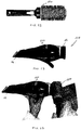
- the attachment 10 is generally made of an appropriate polymeric material.
- the attachment comprises a hollow base section 12 sized for attachment to the air exit of a blow-dryer (see Fig.13 ).
- a fishtail section 14 extends from the base section 12 and is comprised of two opposite substantially flat walls 18 and 20. Walls 18 and 20 together with edges 21 and 23 respectively, terminate in an elongated nozzle 16.
- Wall 20 has a relatively large cut out section 22 ( Figure 4 ), the purpose of which will be discussed later on.
- a heat conducting plate 24 is mounted on the outside of wall 20 covering the cut out section 22 and the outside of nozzle 16. The plate 24 is fastened to the wall 20 with a pin 25.
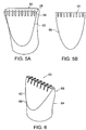
- Fig. 5A is a perspective view of a nozzle attachment device 50, in accordance with another embodiment of the present invention.
- Nozzle attachment 50 differs from attachment 10 shown in Figs. 1-4 , in that fishtail section 52 includes a plurality of protruding fins 54 along the edge of the wall 52 near nozzle 28. These fins 54 traverse slits 55 in the heat conducting plate 56 (seen in Fig. 5B ).
- the protruding fins 54 are integral parts of the device 50 and are preferably from the same non-conducting polymeric material. These protruding fins 54 act as safety barriers, that prevent direct contact between the scalp and conducting plate 56, thus protecting the scalp from getting overheated and even burned.
- the number and the shape of protruding fins 54 may of course vary, as long as there is a separation between the conducting plate and the edge of the nozzle.
- Fig. 6 shows a nozzle attachment 60 having heat conducting plates 62, 64 (not visible) mounted on both flat walls 66, 68 of the attachment 60.
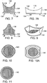
- the attachment 116 is generally made of an appropriate polymeric material and comprises a ring shaped base section 132 sized for attachment to the air intake 114 of a blow-dryer 110.
- the base section 132 has means 134 for mounting the attachment to the air intake of the dryer/blower.
- a cylindrical wall 136 extends from the base section 132 and terminates in a curvature 138 contoured to engage a round hair brush 120 as shown in Figs. 12 and 14 .
- the ring shaped base section 132 preferably has a wire mesh filter 140 to prevent foreign objects to be sucked into the dryer/blower 110.
- FIGS. 13 and 14 there is illustrated a hair dryer/blower 100 with a nozzle attachment device 112 at one end through which heated air is blown and at other end of the dryer/blower 100 is an air intake attachment 116 through which atmospheric air 114 is drawn.
- FIG. 14 illustrates the dryer/blower 110 with the air intake attachment 116 in operation. The attachment 116 is placed directly against the hair 118 on the brush 120, and as cool air is sucked into the dryer/blower 110 and cools the hair 118 prior to entering the dryer/blower 110 where it may be heated. The cool air passes through the brush 120 and hair 118.
- the attachments of this invention are used as follows.
- a person usually a hair-dresser, uses the blow dryer with attachments together with a hair brush.
- the hair dresser/person gathers a portion of wetted hair with a hair brush and extends it away from the person's head. While brushing the wet thick and/or curly hair with one hand the hair-dresser/person contacts the hair with the heat conducting plate of the nozzle attachment with the other hand.
- the hot air coming from the blow dryer heats the conducting plate which retains and increases the heat thus drying and fixing the shape of the hair more permanently.
- the hair blow dryer can be used either with the wall having the heat conducting plate facing the scalp or in an inverted position with the other polymeric material wall facing the scalp, thus giving the hair-dresser greater flexibility.
- the fins prevent touching the skin or scalp with the heated plate.
- the hair dresser/person then turns the hair dryer/blower around and places the air intake with the air intake attachment against the hair on the hair brush to cool the hair. This process of heating and cooling is often repeated a number of times to permanently set the hair.
- Hair dryer/blowers can be used with either the nozzle attachment or air intake attachment mounted thereon or with both of these attached.
- nozzle attachment and/or air intake attachment can be formed as an integral part of the dryer/blower housing.
Description
- The present invention relates to hair styling products for use with hair dryers and the like. More particularly, the present invention relates to attachments for a hair dryer including an attachment to the air outlet for drying hair and an attachment to the air intake to cool heated hair. The invention also relates to a hair dryer/blower with such attachments mounted thereon or integrated therewith.
- Hair generally is formed with a cuticle (the outer layer), a cortex (an inner layer), and a medulla (the innermost layer). The spiraling nature of naturally curly hair, particularly black hair, is caused by the shaft of the hair having a flat cross-section. Additionally, the cuticle of the hair serves to maintain the curly nature of the hair through a thick and durable covering of keratin proteins.
- It has often been a desire of people having curly hair to straighten their hair, such as by combing and/or brushing the hair. A number of combs have been designed specifically for use with curly hair, such as the Afro pick, and a comb having holes along the spine of the comb to allow the hair a space to turn and unwind. Despite these straightening actions, however, the hair is only pulled straight for an instant, and due to the curly nature of the hair, the hair returns to its original curvature.
- In order to keep the hair in a straightened state, a chemical relaxer is often applied to the hair. Chemical relaxers typically consist of a strong alkaline chemical, such as lye, and require that hair care technicians exhibit a great deal of caution in order to avoid damaging the hair, or burning the scalp of the person being treated. Moreover, due to the harshness of the chemical relaxers, it is important that the chemicals are only left on the hair for a limited period of time. In fact, chemicals left on the hair too long may even result in the hair breaking.
- As an alternative to the chemical straighteners, the hair may be straightened by pressing and curling the hair. Pressing includes the application of extreme heat to the hair in order to "press out" the curls. One device used in the pressing process is a pressing comb, also known as the straightening comb. The pressing comb is made of a heavy metal and formed with a single row of teeth. The heavy metal material allows for the comb to be heated, such as by placing the comb in a heating device, and then retains the heat during the combing process. In this manner, the hair is heated and combed straight at the same time, resulting in the hair remaining in its straightened state. However, with moisture, the hair will revert back to its natural, curly state, necessitating the hair being straightened again. Consequently, it is possible that a person having curly hair could need to straighten their hair several times a week.
- Another method used for straightening hair, for example, is where the user may employ a hair brush to place tension on his or her hair while applying heated air with a hair dryer. In particular, the user gathers a portion of hair and extends it away from his or her head. The extended hair portion is then treated with heated air to enable it to retain its extended shape. However, the heated air is often insufficient to adequately dry the hair to maintain it in a straightened condition.
- In another similar method, a blow dryer nozzle having two rows of teeth is used. The teeth are separated to allow the air from the blow dryer to flow between the teeth to heat the hair during the combing process. While this nozzle provides localized heating for the rapid evaporation of any moisture within the hair, it is considerably cooler than the straightening comb, and therefore does not provide the same straightening effect.
-
US Patent No. 5,729,907 describes an attachment for a hair dryer containing on its upper section a curved heat transmitting plate with a comb extending from one side. The heat transmitting plate has a significant surface area and thus requires spaced ridges to prevent contact of scalp and fingers with the heat transmitting plate. -
US Patent No. 6,009,883 discloses an improved blow dryer nozzle having two parallel rows of teeth disposed on opposite sides of the nozzle with a steel heating bar situated between the two rows of teeth. The steel heating bar extends slightly higher than the base of the teeth for striking the hair within the teeth. As the hair passes over the heating bar, the heated bar straightens the hair, much like the effects of using a traditional straightening comb. - Thus, the main concern of improvements to hair dryers was to enable the blower to supply sufficient hot air to dry the hair quickly. However, it is often desired to cool the hair right after having shaped it with the heated air from the blower nozzle. A common method of cooling the hair while being shaped with a round brush is to reverse the hair dryer and place the air intake against the hair on the brush. This sucks room temperature air through the hair to cool them. This method, although widespread, is not very efficient in that the suction is quite weak and takes long to dry the hair.
US 4 409 998 A discloses a device according to the preambles ofclaims 1 and 12. - The present invention is defined by the scope of appended
claims 1 and 12. - Against the foregoing background, it is a primary object of the present invention to provide a hair dryer/blower, in particular for use by professional hair dressers, with an attachment to straighten the hair quickly with the aid of a hair brush and/or an attachment to cool the hair efficiently while straightening or styling the hair with the aid of a hair brush.
- Another object of the present invention is to provide an attachment for a professional hair dryer/blower that helps straighten the hair by optionally drawing the hair with a hair brush across a heat conducting surface of the attachment.
- A still further object of the present invention to provide an attachment for a professional hair dryer/blower that provides high volume concentrated ambient air flow to the dryer/blower.
- Still another object of the invention is to provide an attachment for a hair dryer/blower that will aid in cooling the hair more efficiently.
- Yet another object of the invention is to provide a method of styling or straightening hair with a brush and hair dryer/blower, by alternating heating and cooling the hair.
- In another embodiment, the heat conducting plate overlaps and curves inward into the nozzle on the side of the plate. This prevents any possible scratching of scalp or fingers by the edge of the heat conducting plate.
- In yet another embodiment, there are provided heat conducting plates on both flat walls or the nozzle attachment to maximize the hot air dispensed by the hair dryer/blower.
- In a most preferred embodiment, the nozzle attachment has means, such as fins, that space the heat conducting plate away from contact with the scalp of the person using the dryer/blower.
- The heat conducting plate can be of any metal or other like material, such as of ceramic, with a steel plate being preferred in that it does not corrode.
- It is also contemplated within the present invention that a nozzle attachment as defined above be integrally molded as part of the dryer/blower housing.
- The method of using the dryer/blower with the nozzle attachment is quite simple. A hair dresser, or for that matter anyone desiring to shape/straighten thick/curly hair attaches the inventive nozzle attachment to a hair blow dryer and works up the hair with a hair brush in a conventional manner. However, he/she contacts the hair that is being shaped with the brush, with the air passing over the heat conducting plate of the nozzle attachment which has been heated to a high temperature, to fix the shape of the hair.
- In a preferred embodiment the cylindrical wall extending from the base section flares out to provide a larger air intake area.
- It is preferred that the air intake attachment have filter means to prevent undesirable objects from entering the dryer/blower mechanism.
- The air intake of the dryer/blower can have the cylindrical extension integrally molded therewith terminating with a curvature conforming to a round hair brush, or it can have as a separate attachment with a cylindrical wall terminating with a proper curvature that can be mounted on a conventional air intake of a dryer/blower.
- The air intake attachment thus provides a simple and efficient means for using the dryer/blower to cool hair quickly right after being heated and straightened or shaped by the hair blower. Thus the invention provides a hair dryer/blower with dual capabilities, to heat the hair and subsequently cool it efficiently. A hair dresser can thus use the same dryer/blower by first blowing hot air unto the hair while brushing it to straighten it out and then turn the dryer/blower around quickly to cool the hair as necessary and repeat this procedure as needed.
- The foregoing and still further objects and advantages of the present invention will be more apparent from the following detailed explanation of the preferred embodiments of the invention in connection with the accompanying drawings:
-
FIG. 1 is a view of one side of a nozzle attachment device in accordance with an embodiment of the present invention; -
FIG. 2 is a view of the other side of the attachment device ofFig.1 -
FIG. 3 is a top view of the attachment device ofFig. 1 -
FIG. 4 is a cross sectional view across A - A ofFigure 3 showing theinside wall 22 ofFigure 2 ; -
Fig. 5A is a perspective view of another embodiment of a nozzle attachment device in accordance with the present invention; and -
Fig. 5B is a front view of the heat conducting plate of the nozzle attachment device illustrated inFig. 5 . -
Fig. 6 illustrates a nozzle attachment in accordance with the present invention wherein heat conducting plates are mounted on two sides of the attachment. -
Figs. 7 and 7A are plan views of an air intake attachment device in accordance with this invention; -
Fig. 8 is a plan view of the air intake attachment shown infigure 7 turned 90 degrees; -
Fig. 9 is a perspective view of an air intake attachment in accordance with this invention. -
FIGS.10 and 10A are views of the air intake attachment as seen from above; -
FIG.11 is a view of the air intake attachment seen from below; -
FIG. 12 shows a round hair brush for use with a dryer/blower in accordance with the present invention. -
FIG. 13 is a plan view of a hair dryer/blower with attachments in accordance with this invention; -
FIG. 14 is a plan view of a hair dryer/blower in accordance with this invention as it is used with a hair brush; - Referring to
FIGS. 1 to 4 , there is illustrated a preferred embodiment of a hair dryer nozzle attachment 10. The attachment 10 is generally made of an appropriate polymeric material. The attachment comprises ahollow base section 12 sized for attachment to the air exit of a blow-dryer (seeFig.13 ). Afishtail section 14 extends from thebase section 12 and is comprised of two opposite substantiallyflat walls Walls edges elongated nozzle 16.Wall 20 has a relatively large cut out section 22 (Figure 4 ), the purpose of which will be discussed later on. Aheat conducting plate 24 is mounted on the outside ofwall 20 covering the cut outsection 22 and the outside ofnozzle 16. Theplate 24 is fastened to thewall 20 with apin 25. In a preferred embodiment theheat conducting plate 24 is bent 26 over the edge of thenozzle wall 28 on the side ofwall 20. The preferred embodiment has the advantage that the heat conducting plate does not end at the tip of the nozzle with a sharp edge that may cut or injure a person's hair or scalp.
Referring toFig. 5A which is a perspective view of anozzle attachment device 50, in accordance with another embodiment of the present invention.Nozzle attachment 50 differs from attachment 10 shown inFigs. 1-4 , in thatfishtail section 52 includes a plurality of protrudingfins 54 along the edge of thewall 52 nearnozzle 28. Thesefins 54 traverse slits 55 in the heat conducting plate 56 (seen inFig. 5B ). The protrudingfins 54 are integral parts of thedevice 50 and are preferably from the same non-conducting polymeric material. These protrudingfins 54 act as safety barriers, that prevent direct contact between the scalp and conductingplate 56, thus protecting the scalp from getting overheated and even burned.
The number and the shape of protrudingfins 54 may of course vary, as long as there is a separation between the conducting plate and the edge of the nozzle. According to yet another embodiment of the nozzle attachment of the present invention, there can be a single protruding piece (not shown) along the edge of thenozzle wall 28 instead of protrudingfins 54. In this case, the scalp is even better protected from contacting conductingplate 56.Fig. 6 shows anozzle attachment 60 havingheat conducting plates 62, 64 (not visible) mounted on bothflat walls attachment 60. - Referring now to
FIGS 7 to 11 there is shown anair intake attachment 116 for mounting onto the air intake of a hair dryer/blower (seeFig.13 ). Theattachment 116 is generally made of an appropriate polymeric material and comprises a ring shapedbase section 132 sized for attachment to theair intake 114 of a blow-dryer 110. Thebase section 132 hasmeans 134 for mounting the attachment to the air intake of the dryer/blower. Acylindrical wall 136 extends from thebase section 132 and terminates in acurvature 138 contoured to engage around hair brush 120 as shown inFigs. 12 and 14 . The ring shapedbase section 132 preferably has awire mesh filter 140 to prevent foreign objects to be sucked into the dryer/blower 110.
Referring toFIGS. 13 and 14 , there is illustrated a hair dryer/blower 100 with a nozzle attachment device 112 at one end through which heated air is blown and at other end of the dryer/blower 100 is anair intake attachment 116 through whichatmospheric air 114 is drawn.FIG. 14 illustrates the dryer/blower 110 with theair intake attachment 116 in operation. Theattachment 116 is placed directly against thehair 118 on thebrush 120, and as cool air is sucked into the dryer/blower 110 and cools thehair 118 prior to entering the dryer/blower 110 where it may be heated. The cool air passes through thebrush 120 andhair 118. - The attachments of this invention are used as follows. A person, usually a hair-dresser, uses the blow dryer with attachments together with a hair brush. The hair dresser/person gathers a portion of wetted hair with a hair brush and extends it away from the person's head. While brushing the wet thick and/or curly hair with one hand the hair-dresser/person contacts the hair with the heat conducting plate of the nozzle attachment with the other hand. The hot air coming from the blow dryer heats the conducting plate which retains and increases the heat thus drying and fixing the shape of the hair more permanently. When the heat conducting plate is only on one outside wall of the attachment the hair blow dryer can be used either with the wall having the heat conducting plate facing the scalp or in an inverted position with the other polymeric material wall facing the scalp, thus giving the hair-dresser greater flexibility. In embodiments having nozzle attachments with fins protruding beyond the conducting plate, the fins prevent touching the skin or scalp with the heated plate. The hair dresser/person then turns the hair dryer/blower around and places the air intake with the air intake attachment against the hair on the hair brush to cool the hair. This process of heating and cooling is often repeated a number of times to permanently set the hair.
- Hair dryer/blowers can be used with either the nozzle attachment or air intake attachment mounted thereon or with both of these attached.
- It is contemplated within the concept of this invention that the nozzle attachment and/or air intake attachment can be formed as an integral part of the dryer/blower housing.
Claims (11)
- A hair dryer/blower (110) for use in straightening or styling hair with a round hair brush (120), said hair dryer/blower (110) comprising:a hot air outlet through which hot air is blown;an air inlet for sucking in air at room temperature;an attachment (10, 50) to the hot air outlet; andan attachment (116) to the air inlet,the attachment (10, 50) to the hot air outlet comprising a heat conducting device terminating in a flat elongated nozzle (16),whereby when the dryer/blower (110) is turned on to blow hot air through the outlet (10, 50), the hot air passes over the heat conducting device raising the temperature so that when the edge of the nozzle (16) is drawn over wet hair that is being shaped with a hair brush (120) the hair is fixed in the shaped condition due to the drying at a higher temperature, andcharacterized in thatthe attachment (116) to the air inlet comprises a terminal shape with a curvature conforming to the curvature of a round hair brush (120) used in shaping the hair thereby maximizing the flow of cool air through the hair when the attachment (116) is brought in direct contact with heated air on the round brush (120) as the ambient temperature is sucked through the hair and brush (120) at high volume and maximum force.
- A hair dryer/blower in accordance with claim 1, wherein the attachment (10, 50) to the hot air outlet comprises a hollow body, comprising: a base section (12) sized for attachment to a blow/dryer (110), a fishtail section (14, 52) extending from the base section terminating in the nozzle (16) with an elongated opening, the fishtail section (14, 52) comprising two parallel flat walls (18, 20) and side walls with one flat wall (18, 20) having a cut out section (22) in its center, a heat conducting plate (24) mounted on the outer surface of the one flat wall (18, 20) up to the opening of the nozzle (16).
- A hair dryer/blower in accordance with claim 2, wherein the attachment (10) to the hot air outlet comprises a heat conducting plate (24) bent over to cover the elongated edge of the nozzle (16) extending into the opening of the nozzle (16).
- A hair dryer/blower in accordance with claim 2, wherein the flat wall (18, 20) on which the heat conducting plate (24) is mounted has a protruding extension along its edge at the nozzle (16), distancing the conducting plate (24) from the nozzle (16) to prevent contact of the heat conducting plate (24) with the neck or scalp when operating the device.
- A hair dryer/blower in accordance with claim 4, wherein the protruding extension comprises fins (54) traversing slots (55) in the heat conducting plate.
- A hair dryer/blower according to any one of claims 2 to 4, wherein both flat walls (18, 20) of the attachment (10) have cut out sections in their centers and heat conducting plates are mounted on both flat walls.
- A hair dryer/blower according to any one of claims 2 to 5, wherein the heat conducting plate (24) of the attachment (10) is a steel plate.
- A hair dryer/blower in accordance with claim 1, wherein the attachment (116) to the air inlet comprises:a ring shaped base section (132) sized for attachment to the air intake of the blow-dryer (110),means (134) for mounting the attachment (116) to the air intake of the dryer/blower (110), anda cylindrical wall (136) extending from the base section (132), said wall (136) terminating with a curvature (138) contoured to engage a round hair brush (120).
- A hair dryer/blower in accordance with claim 8, wherein the base section (132) of the attachment (116) comprises a filter (140).
- A hair dryer/blower in accordance with claim 9, wherein the filter (140) is a wire mesh filter (140).
- A method of straightening or styling hair with the aid of a hair dryer/blower (110) and round hairbrush (120) comprising:providing a hair dryer/blower (110) in accordance with any one of claims 1 to 7;brushing the hair with a round brush (120) while applying heat through the hot air outlet, reversing the dryer/blower (110) and placing the air intake attachment (116) with the contoured curvature (138) against the hair on the round hairbrush (120) to maximize the flow of air through the hair and cool it; andrepeating the cycle of heating/cooling the hair as needed to straighten or style the hair.
Priority Applications (2)
| Application Number | Priority Date | Filing Date | Title |
|---|---|---|---|
| SI201031720T SI2496111T1 (en) | 2009-11-04 | 2010-10-28 | Hair styling attachment |
| PL10787197T PL2496111T3 (en) | 2009-11-04 | 2010-10-28 | Hair styling attachment |
Applications Claiming Priority (3)
| Application Number | Priority Date | Filing Date | Title |
|---|---|---|---|
| IL201914A IL201914A (en) | 2009-11-04 | 2009-11-04 | Hair styling attachment |
| IL20369310 | 2010-02-03 | ||
| PCT/IL2010/000889 WO2011055360A1 (en) | 2009-11-04 | 2010-10-28 | Hair styling attachment |
Publications (2)
| Publication Number | Publication Date |
|---|---|
| EP2496111A1 EP2496111A1 (en) | 2012-09-12 |
| EP2496111B1 true EP2496111B1 (en) | 2018-04-18 |
Family
ID=43365856
Family Applications (1)
| Application Number | Title | Priority Date | Filing Date |
|---|---|---|---|
| EP10787197.2A Active EP2496111B1 (en) | 2009-11-04 | 2010-10-28 | Hair styling attachment |
Country Status (11)
| Country | Link |
|---|---|
| US (1) | US9622561B2 (en) |
| EP (1) | EP2496111B1 (en) |
| AU (1) | AU2010316649B2 (en) |
| BR (1) | BR112012010677A2 (en) |
| CA (1) | CA2780047C (en) |
| ES (1) | ES2683120T3 (en) |
| NZ (1) | NZ600417A (en) |
| PL (1) | PL2496111T3 (en) |
| SI (1) | SI2496111T1 (en) |
| TR (1) | TR201810224T4 (en) |
| WO (1) | WO2011055360A1 (en) |
Families Citing this family (10)
| Publication number | Priority date | Publication date | Assignee | Title |
|---|---|---|---|---|
| GB2540203B (en) * | 2015-07-10 | 2018-07-25 | Dyson Technology Ltd | Nozzle |
| EP3432757B1 (en) | 2016-03-24 | 2021-02-17 | Dyson Technology Limited | Attachment for a handheld appliance |
| USD814700S1 (en) * | 2016-05-04 | 2018-04-03 | J & D Brush Co., Llc | Nozzle |
| US10856639B2 (en) * | 2017-02-07 | 2020-12-08 | Beny Molayev | Styling hair dryer nozzle |
| USD833069S1 (en) | 2017-05-26 | 2018-11-06 | Master Salon Technologies LLC | Hair dryer attachment |
| USD872935S1 (en) * | 2017-10-18 | 2020-01-14 | JMW Co., Ltd. | Air nozzle for hair dryer |
| JP1706979S (en) * | 2021-03-02 | 2022-02-07 | Accessories for hair care equipment | |
| JP1707007S (en) * | 2021-06-29 | 2022-02-07 | Accessories for hair care equipment | |
| USD1000703S1 (en) * | 2021-06-29 | 2023-10-03 | Dyson Technology Limited | Accessory for a hairdryer |
| USD1001371S1 (en) * | 2021-06-29 | 2023-10-10 | Dyson Technology Limited | Accessory for a hairdryer |
Citations (1)
| Publication number | Priority date | Publication date | Assignee | Title |
|---|---|---|---|---|
| WO2006001657A1 (en) * | 2004-06-24 | 2006-01-05 | Saint Coree Int. Co., Ltd. | Hair dryer with function for cleaning hair |
Family Cites Families (10)
| Publication number | Priority date | Publication date | Assignee | Title |
|---|---|---|---|---|
| US4368376A (en) * | 1979-07-23 | 1983-01-11 | Andis Company | Curling iron with removable grooming bars |
| CH635238A5 (en) * | 1980-02-13 | 1983-03-31 | Jose Giordano | NOZZLE FOR HAIR DRYER. |
| DE3043470A1 (en) * | 1980-11-18 | 1982-06-09 | Rudolf 7000 Stuttgart Bauer | HAIRDRESSER FOR THE SIMULTANEOUS ROLLING AND SHAPING, DEHUMIDIFYING AND DRYING OF HEAD HAIR |
| US4479311A (en) * | 1981-01-27 | 1984-10-30 | Blanco David M | Hair removing apparatus |
| DE4204893A1 (en) * | 1992-02-19 | 1993-08-26 | Rbi Distributors Inc | INLET FILTER FOR HAIR FROEN |
| US5729907A (en) | 1996-09-27 | 1998-03-24 | Conair Corporation | Hair straightening pick |
| US6009883A (en) | 1998-07-22 | 2000-01-04 | Morrow; Willie L. | Hair straightening nozzle |
| US6922909B2 (en) * | 2003-01-06 | 2005-08-02 | Rovcal, Inc. | Attachment for hair dryers |
| US6959501B1 (en) * | 2004-02-27 | 2005-11-01 | Patricia Melzer | Hair styling vacuum device |
| US20050229423A1 (en) * | 2004-04-14 | 2005-10-20 | Kenford Industrial Company Ltd. | Nozzle having thermal-capacitance element |
-
2010
- 2010-10-28 AU AU2010316649A patent/AU2010316649B2/en not_active Ceased
- 2010-10-28 WO PCT/IL2010/000889 patent/WO2011055360A1/en active Application Filing
- 2010-10-28 EP EP10787197.2A patent/EP2496111B1/en active Active
- 2010-10-28 SI SI201031720T patent/SI2496111T1/en unknown
- 2010-10-28 PL PL10787197T patent/PL2496111T3/en unknown
- 2010-10-28 NZ NZ600417A patent/NZ600417A/en not_active IP Right Cessation
- 2010-10-28 US US13/505,580 patent/US9622561B2/en not_active Expired - Fee Related
- 2010-10-28 ES ES10787197.2T patent/ES2683120T3/en active Active
- 2010-10-28 BR BR112012010677A patent/BR112012010677A2/en not_active IP Right Cessation
- 2010-10-28 TR TR2018/10224T patent/TR201810224T4/en unknown
- 2010-10-28 CA CA2780047A patent/CA2780047C/en not_active Expired - Fee Related
Patent Citations (1)
| Publication number | Priority date | Publication date | Assignee | Title |
|---|---|---|---|---|
| WO2006001657A1 (en) * | 2004-06-24 | 2006-01-05 | Saint Coree Int. Co., Ltd. | Hair dryer with function for cleaning hair |
Also Published As
| Publication number | Publication date |
|---|---|
| NZ600417A (en) | 2014-10-31 |
| US20120234343A1 (en) | 2012-09-20 |
| AU2010316649A1 (en) | 2012-06-21 |
| CA2780047A1 (en) | 2011-05-12 |
| PL2496111T4 (en) | 2018-10-31 |
| EP2496111A1 (en) | 2012-09-12 |
| US9622561B2 (en) | 2017-04-18 |
| ES2683120T3 (en) | 2018-09-25 |
| WO2011055360A1 (en) | 2011-05-12 |
| CA2780047C (en) | 2018-11-27 |
| AU2010316649B2 (en) | 2016-04-14 |
| PL2496111T3 (en) | 2018-10-31 |
| BR112012010677A2 (en) | 2016-04-12 |
| SI2496111T1 (en) | 2018-09-28 |
| TR201810224T4 (en) | 2018-08-27 |
| WO2011055360A4 (en) | 2011-06-30 |
Similar Documents
| Publication | Publication Date | Title |
|---|---|---|
| EP2496111B1 (en) | Hair styling attachment | |
| DK1916922T3 (en) | Hårstylingsindretning | |
| US7152610B2 (en) | Hair care attachments and devices | |
| US20140033558A1 (en) | Hair styler | |
| EP2613663B1 (en) | A combined device for treating the hair | |
| KR100455741B1 (en) | hair brush | |
| US20050109755A1 (en) | Hair straightening device | |
| KR200262444Y1 (en) | Electric Comb | |
| KR200460464Y1 (en) | Hair Brush | |
| KR101507391B1 (en) | Hair dryer diffusers | |
| US20210015231A1 (en) | Melamine foam hair apparatus | |
| JP2001519705A (en) | Hair drying and styling tools | |
| CN220369635U (en) | Device for drying hair and styling hair | |
| KR200452425Y1 (en) | Hair dryer with drying and hair-styling | |
| KR200483630Y1 (en) | Hair brush | |
| TWI351934B (en) | ||
| KR101566121B1 (en) | Hair curl implement | |
| KR100372198B1 (en) | Hair curling device | |
| CN107536224B (en) | Electric heating comb | |
| KR200190819Y1 (en) | An airing type roll brush for hairdressing | |
| AU2002362716A1 (en) | Hair care attachments and devices | |
| KR20160141698A (en) | Hair brush | |
| KR20110000819U (en) | A structure of diffuser for hairdryer | |
| JPH05245005A (en) | Steam hair curler |
Legal Events
| Date | Code | Title | Description |
|---|---|---|---|
| PUAI | Public reference made under article 153(3) epc to a published international application that has entered the european phase |
Free format text: ORIGINAL CODE: 0009012 |
|
| 17P | Request for examination filed |
Effective date: 20120601 |
|
| AK | Designated contracting states |
Kind code of ref document: A1 Designated state(s): AL AT BE BG CH CY CZ DE DK EE ES FI FR GB GR HR HU IE IS IT LI LT LU LV MC MK MT NL NO PL PT RO RS SE SI SK SM TR |
|
| DAX | Request for extension of the european patent (deleted) | ||
| 17Q | First examination report despatched |
Effective date: 20170403 |
|
| GRAP | Despatch of communication of intention to grant a patent |
Free format text: ORIGINAL CODE: EPIDOSNIGR1 |
|
| INTG | Intention to grant announced |
Effective date: 20171027 |
|
| GRAS | Grant fee paid |
Free format text: ORIGINAL CODE: EPIDOSNIGR3 |
|
| GRAA | (expected) grant |
Free format text: ORIGINAL CODE: 0009210 |
|
| AK | Designated contracting states |
Kind code of ref document: B1 Designated state(s): AL AT BE BG CH CY CZ DE DK EE ES FI FR GB GR HR HU IE IS IT LI LT LU LV MC MK MT NL NO PL PT RO RS SE SI SK SM TR |
|
| REG | Reference to a national code |
Ref country code: GB Ref legal event code: FG4D |
|
| REG | Reference to a national code |
Ref country code: CH Ref legal event code: EP |
|
| REG | Reference to a national code |
Ref country code: AT Ref legal event code: REF Ref document number: 989472 Country of ref document: AT Kind code of ref document: T Effective date: 20180515 |
|
| REG | Reference to a national code |
Ref country code: IE Ref legal event code: FG4D |
|
| REG | Reference to a national code |
Ref country code: DE Ref legal event code: R096 Ref document number: 602010050048 Country of ref document: DE |
|
| REG | Reference to a national code |
Ref country code: NL Ref legal event code: FP |
|
| REG | Reference to a national code |
Ref country code: SE Ref legal event code: TRGR |
|
| REG | Reference to a national code |
Ref country code: LT Ref legal event code: MG4D |
|
| REG | Reference to a national code |
Ref country code: ES Ref legal event code: FG2A Ref document number: 2683120 Country of ref document: ES Kind code of ref document: T3 Effective date: 20180925 |
|
| PG25 | Lapsed in a contracting state [announced via postgrant information from national office to epo] |
Ref country code: LT Free format text: LAPSE BECAUSE OF FAILURE TO SUBMIT A TRANSLATION OF THE DESCRIPTION OR TO PAY THE FEE WITHIN THE PRESCRIBED TIME-LIMIT Effective date: 20180418 Ref country code: BG Free format text: LAPSE BECAUSE OF FAILURE TO SUBMIT A TRANSLATION OF THE DESCRIPTION OR TO PAY THE FEE WITHIN THE PRESCRIBED TIME-LIMIT Effective date: 20180718 Ref country code: FI Free format text: LAPSE BECAUSE OF FAILURE TO SUBMIT A TRANSLATION OF THE DESCRIPTION OR TO PAY THE FEE WITHIN THE PRESCRIBED TIME-LIMIT Effective date: 20180418 Ref country code: AL Free format text: LAPSE BECAUSE OF FAILURE TO SUBMIT A TRANSLATION OF THE DESCRIPTION OR TO PAY THE FEE WITHIN THE PRESCRIBED TIME-LIMIT Effective date: 20180418 Ref country code: NO Free format text: LAPSE BECAUSE OF FAILURE TO SUBMIT A TRANSLATION OF THE DESCRIPTION OR TO PAY THE FEE WITHIN THE PRESCRIBED TIME-LIMIT Effective date: 20180718 |
|
| PG25 | Lapsed in a contracting state [announced via postgrant information from national office to epo] |
Ref country code: HR Free format text: LAPSE BECAUSE OF FAILURE TO SUBMIT A TRANSLATION OF THE DESCRIPTION OR TO PAY THE FEE WITHIN THE PRESCRIBED TIME-LIMIT Effective date: 20180418 Ref country code: GR Free format text: LAPSE BECAUSE OF FAILURE TO SUBMIT A TRANSLATION OF THE DESCRIPTION OR TO PAY THE FEE WITHIN THE PRESCRIBED TIME-LIMIT Effective date: 20180719 Ref country code: LV Free format text: LAPSE BECAUSE OF FAILURE TO SUBMIT A TRANSLATION OF THE DESCRIPTION OR TO PAY THE FEE WITHIN THE PRESCRIBED TIME-LIMIT Effective date: 20180418 Ref country code: RS Free format text: LAPSE BECAUSE OF FAILURE TO SUBMIT A TRANSLATION OF THE DESCRIPTION OR TO PAY THE FEE WITHIN THE PRESCRIBED TIME-LIMIT Effective date: 20180418 |
|
| PG25 | Lapsed in a contracting state [announced via postgrant information from national office to epo] |
Ref country code: PT Free format text: LAPSE BECAUSE OF FAILURE TO SUBMIT A TRANSLATION OF THE DESCRIPTION OR TO PAY THE FEE WITHIN THE PRESCRIBED TIME-LIMIT Effective date: 20180820 |
|
| REG | Reference to a national code |
Ref country code: DE Ref legal event code: R097 Ref document number: 602010050048 Country of ref document: DE |
|
| PG25 | Lapsed in a contracting state [announced via postgrant information from national office to epo] |
Ref country code: CZ Free format text: LAPSE BECAUSE OF FAILURE TO SUBMIT A TRANSLATION OF THE DESCRIPTION OR TO PAY THE FEE WITHIN THE PRESCRIBED TIME-LIMIT Effective date: 20180418 Ref country code: RO Free format text: LAPSE BECAUSE OF FAILURE TO SUBMIT A TRANSLATION OF THE DESCRIPTION OR TO PAY THE FEE WITHIN THE PRESCRIBED TIME-LIMIT Effective date: 20180418 Ref country code: SK Free format text: LAPSE BECAUSE OF FAILURE TO SUBMIT A TRANSLATION OF THE DESCRIPTION OR TO PAY THE FEE WITHIN THE PRESCRIBED TIME-LIMIT Effective date: 20180418 Ref country code: EE Free format text: LAPSE BECAUSE OF FAILURE TO SUBMIT A TRANSLATION OF THE DESCRIPTION OR TO PAY THE FEE WITHIN THE PRESCRIBED TIME-LIMIT Effective date: 20180418 Ref country code: DK Free format text: LAPSE BECAUSE OF FAILURE TO SUBMIT A TRANSLATION OF THE DESCRIPTION OR TO PAY THE FEE WITHIN THE PRESCRIBED TIME-LIMIT Effective date: 20180418 |
|
| PLBE | No opposition filed within time limit |
Free format text: ORIGINAL CODE: 0009261 |
|
| STAA | Information on the status of an ep patent application or granted ep patent |
Free format text: STATUS: NO OPPOSITION FILED WITHIN TIME LIMIT |
|
| PG25 | Lapsed in a contracting state [announced via postgrant information from national office to epo] |
Ref country code: SM Free format text: LAPSE BECAUSE OF FAILURE TO SUBMIT A TRANSLATION OF THE DESCRIPTION OR TO PAY THE FEE WITHIN THE PRESCRIBED TIME-LIMIT Effective date: 20180418 |
|
| 26N | No opposition filed |
Effective date: 20190121 |
|
| REG | Reference to a national code |
Ref country code: DE Ref legal event code: R119 Ref document number: 602010050048 Country of ref document: DE |
|
| REG | Reference to a national code |
Ref country code: SE Ref legal event code: EUG |
|
| REG | Reference to a national code |
Ref country code: CH Ref legal event code: PL |
|
| REG | Reference to a national code |
Ref country code: NL Ref legal event code: MM Effective date: 20181101 |
|
| GBPC | Gb: european patent ceased through non-payment of renewal fee |
Effective date: 20181028 |
|
| REG | Reference to a national code |
Ref country code: BE Ref legal event code: MM Effective date: 20181031 |
|
| PG25 | Lapsed in a contracting state [announced via postgrant information from national office to epo] |
Ref country code: LU Free format text: LAPSE BECAUSE OF NON-PAYMENT OF DUE FEES Effective date: 20181028 Ref country code: MC Free format text: LAPSE BECAUSE OF FAILURE TO SUBMIT A TRANSLATION OF THE DESCRIPTION OR TO PAY THE FEE WITHIN THE PRESCRIBED TIME-LIMIT Effective date: 20180418 |
|
| REG | Reference to a national code |
Ref country code: IE Ref legal event code: MM4A |
|
| PG25 | Lapsed in a contracting state [announced via postgrant information from national office to epo] |
Ref country code: DE Free format text: LAPSE BECAUSE OF NON-PAYMENT OF DUE FEES Effective date: 20190501 Ref country code: NL Free format text: LAPSE BECAUSE OF NON-PAYMENT OF DUE FEES Effective date: 20181101 Ref country code: SE Free format text: LAPSE BECAUSE OF NON-PAYMENT OF DUE FEES Effective date: 20181029 |
|
| PG25 | Lapsed in a contracting state [announced via postgrant information from national office to epo] |
Ref country code: SI Free format text: LAPSE BECAUSE OF NON-PAYMENT OF DUE FEES Effective date: 20181029 Ref country code: LI Free format text: LAPSE BECAUSE OF NON-PAYMENT OF DUE FEES Effective date: 20181031 Ref country code: FR Free format text: LAPSE BECAUSE OF NON-PAYMENT OF DUE FEES Effective date: 20181031 Ref country code: CH Free format text: LAPSE BECAUSE OF NON-PAYMENT OF DUE FEES Effective date: 20181031 Ref country code: BE Free format text: LAPSE BECAUSE OF NON-PAYMENT OF DUE FEES Effective date: 20181031 |
|
| REG | Reference to a national code |
Ref country code: SI Ref legal event code: KO00 Effective date: 20190701 |
|
| PG25 | Lapsed in a contracting state [announced via postgrant information from national office to epo] |
Ref country code: GB Free format text: LAPSE BECAUSE OF NON-PAYMENT OF DUE FEES Effective date: 20181028 Ref country code: IT Free format text: LAPSE BECAUSE OF NON-PAYMENT OF DUE FEES Effective date: 20181028 Ref country code: IE Free format text: LAPSE BECAUSE OF NON-PAYMENT OF DUE FEES Effective date: 20181028 |
|
| REG | Reference to a national code |
Ref country code: ES Ref legal event code: FD2A Effective date: 20191204 |
|
| REG | Reference to a national code |
Ref country code: AT Ref legal event code: MM01 Ref document number: 989472 Country of ref document: AT Kind code of ref document: T Effective date: 20181028 |
|
| PG25 | Lapsed in a contracting state [announced via postgrant information from national office to epo] |
Ref country code: AT Free format text: LAPSE BECAUSE OF NON-PAYMENT OF DUE FEES Effective date: 20181028 Ref country code: MT Free format text: LAPSE BECAUSE OF NON-PAYMENT OF DUE FEES Effective date: 20181028 |
|
| PG25 | Lapsed in a contracting state [announced via postgrant information from national office to epo] |
Ref country code: ES Free format text: LAPSE BECAUSE OF NON-PAYMENT OF DUE FEES Effective date: 20181029 |
|
| PG25 | Lapsed in a contracting state [announced via postgrant information from national office to epo] |
Ref country code: PL Free format text: LAPSE BECAUSE OF NON-PAYMENT OF DUE FEES Effective date: 20181028 |
|
| PG25 | Lapsed in a contracting state [announced via postgrant information from national office to epo] |
Ref country code: HU Free format text: LAPSE BECAUSE OF FAILURE TO SUBMIT A TRANSLATION OF THE DESCRIPTION OR TO PAY THE FEE WITHIN THE PRESCRIBED TIME-LIMIT; INVALID AB INITIO Effective date: 20101028 Ref country code: CY Free format text: LAPSE BECAUSE OF FAILURE TO SUBMIT A TRANSLATION OF THE DESCRIPTION OR TO PAY THE FEE WITHIN THE PRESCRIBED TIME-LIMIT Effective date: 20180418 Ref country code: MK Free format text: LAPSE BECAUSE OF NON-PAYMENT OF DUE FEES Effective date: 20180418 |
|
| PG25 | Lapsed in a contracting state [announced via postgrant information from national office to epo] |
Ref country code: IS Free format text: LAPSE BECAUSE OF FAILURE TO SUBMIT A TRANSLATION OF THE DESCRIPTION OR TO PAY THE FEE WITHIN THE PRESCRIBED TIME-LIMIT Effective date: 20180818 |
|
| REG | Reference to a national code |
Ref country code: AT Ref legal event code: UEP Ref document number: 989472 Country of ref document: AT Kind code of ref document: T Effective date: 20180418 |