EP2495821A1 - Connector and assembling method therefor - Google Patents
Connector and assembling method therefor Download PDFInfo
- Publication number
- EP2495821A1 EP2495821A1 EP12000845A EP12000845A EP2495821A1 EP 2495821 A1 EP2495821 A1 EP 2495821A1 EP 12000845 A EP12000845 A EP 12000845A EP 12000845 A EP12000845 A EP 12000845A EP 2495821 A1 EP2495821 A1 EP 2495821A1
- Authority
- EP
- European Patent Office
- Prior art keywords
- terminal accommodating
- accommodating chamber
- projection
- terminal
- members
- Prior art date
- Legal status (The legal status is an assumption and is not a legal conclusion. Google has not performed a legal analysis and makes no representation as to the accuracy of the status listed.)
- Withdrawn
Links
- 238000000034 method Methods 0.000 title claims description 12
- 238000004891 communication Methods 0.000 claims abstract description 30
- 230000004308 accommodation Effects 0.000 claims description 9
- 238000001514 detection method Methods 0.000 description 5
- 238000002788 crimping Methods 0.000 description 3
- 230000009471 action Effects 0.000 description 2
- 238000003780 insertion Methods 0.000 description 2
- 230000037431 insertion Effects 0.000 description 2
- 230000000717 retained effect Effects 0.000 description 2
- 229920003002 synthetic resin Polymers 0.000 description 2
- 239000000057 synthetic resin Substances 0.000 description 2
- 239000000470 constituent Substances 0.000 description 1
- 238000010276 construction Methods 0.000 description 1
- 230000001419 dependent effect Effects 0.000 description 1
- 230000006872 improvement Effects 0.000 description 1
- 238000005192 partition Methods 0.000 description 1
- 230000008569 process Effects 0.000 description 1
- 238000000926 separation method Methods 0.000 description 1
Images



Classifications
-
- H—ELECTRICITY
- H01—ELECTRIC ELEMENTS
- H01R—ELECTRICALLY-CONDUCTIVE CONNECTIONS; STRUCTURAL ASSOCIATIONS OF A PLURALITY OF MUTUALLY-INSULATED ELECTRICAL CONNECTING ELEMENTS; COUPLING DEVICES; CURRENT COLLECTORS
- H01R13/00—Details of coupling devices of the kinds covered by groups H01R12/70 or H01R24/00 - H01R33/00
- H01R13/46—Bases; Cases
- H01R13/514—Bases; Cases composed as a modular blocks or assembly, i.e. composed of co-operating parts provided with contact members or holding contact members between them
-
- H—ELECTRICITY
- H01—ELECTRIC ELEMENTS
- H01R—ELECTRICALLY-CONDUCTIVE CONNECTIONS; STRUCTURAL ASSOCIATIONS OF A PLURALITY OF MUTUALLY-INSULATED ELECTRICAL CONNECTING ELEMENTS; COUPLING DEVICES; CURRENT COLLECTORS
- H01R13/00—Details of coupling devices of the kinds covered by groups H01R12/70 or H01R24/00 - H01R33/00
- H01R13/40—Securing contact members in or to a base or case; Insulating of contact members
- H01R13/42—Securing in a demountable manner
- H01R13/436—Securing a plurality of contact members by one locking piece or operation
- H01R13/4361—Insertion of locking piece perpendicular to direction of contact insertion
-
- H—ELECTRICITY
- H01—ELECTRIC ELEMENTS
- H01R—ELECTRICALLY-CONDUCTIVE CONNECTIONS; STRUCTURAL ASSOCIATIONS OF A PLURALITY OF MUTUALLY-INSULATED ELECTRICAL CONNECTING ELEMENTS; COUPLING DEVICES; CURRENT COLLECTORS
- H01R13/00—Details of coupling devices of the kinds covered by groups H01R12/70 or H01R24/00 - H01R33/00
- H01R13/46—Bases; Cases
- H01R13/502—Bases; Cases composed of different pieces
- H01R13/506—Bases; Cases composed of different pieces assembled by snap action of the parts
-
- H—ELECTRICITY
- H01—ELECTRIC ELEMENTS
- H01R—ELECTRICALLY-CONDUCTIVE CONNECTIONS; STRUCTURAL ASSOCIATIONS OF A PLURALITY OF MUTUALLY-INSULATED ELECTRICAL CONNECTING ELEMENTS; COUPLING DEVICES; CURRENT COLLECTORS
- H01R13/00—Details of coupling devices of the kinds covered by groups H01R12/70 or H01R24/00 - H01R33/00
- H01R13/64—Means for preventing incorrect coupling
- H01R13/641—Means for preventing incorrect coupling by indicating incorrect coupling; by indicating correct or full engagement
-
- H—ELECTRICITY
- H01—ELECTRIC ELEMENTS
- H01R—ELECTRICALLY-CONDUCTIVE CONNECTIONS; STRUCTURAL ASSOCIATIONS OF A PLURALITY OF MUTUALLY-INSULATED ELECTRICAL CONNECTING ELEMENTS; COUPLING DEVICES; CURRENT COLLECTORS
- H01R43/00—Apparatus or processes specially adapted for manufacturing, assembling, maintaining, or repairing of line connectors or current collectors or for joining electric conductors
- H01R43/20—Apparatus or processes specially adapted for manufacturing, assembling, maintaining, or repairing of line connectors or current collectors or for joining electric conductors for assembling or disassembling contact members with insulating base, case or sleeve
Definitions
- the present invention relates to a connector and to an assembling method therefor.
- Japanese Unexamined Patent Publication No. 2009-054472 discloses a stacking connector formed by stacking a plurality of housings including terminal accommodating chambers one above another. Each housing is formed with a communication opening formed in an outer surface and communicating with the terminal accommodating chambers, and projections projecting from an outer surface opposite to the communication opening. With the two housings stacked one above the other, the projections of one housing are inserted in the terminal accommodating chambers through the communication opening of the other housing to retain terminal fittings in the terminal accommodating chambers.
- the above stacking connector is housed in a fitting recess of a joint connector, whereby the plurality of housings are held in a stacked state.
- the housings in the stacked state are easily separated.
- an operator needs to hold the housings in the stacked state by the hand so that the housings are not separated from each other. Therefore, there is a demand for an improvement in operability.
- the present invention was completed in view of the above situation and an object thereof is to improve operability.
- a connector comprising a first member including at least one terminal accommodating chamber and at least one communication opening formed in an outer surface and communicating with the terminal accommodating chamber; and a second member including at least one projection projecting from a base portion; wherein the projection at least partly inserted in the terminal accommodating chamber through the communication opening is engaged or to be engaged with a terminal fitting at least partly accommodated in the terminal accommodating chamber to retain the terminal fitting in a state where the second member is assembled by placing the base portion on the outer surface of the first member; the first member includes at least one receiving portion; and the projection includes at least one locking portion for holding the first and second members in an assembled state by being engaged with the receiving portion.
- the receiving portion of the first member and the locking portion of the projection are engaged to hold the first and second members in the assembled state.
- an operator needs not hold the assembled two members by the hand lest the two members should be separated. Therefore, operability is excellent.
- the first and second members are mutually identical housings.
- the housings include both the constituent parts of the first member and those of the second member, they can be used while being stacked.
- each housing includes the terminal accommodating chamber, the communication opening, the projection, the receiving portion and the locking portion.
- the projection interferes with the terminal fitting to make the assembling of the first and second members incomplete and a clearance which is open in a direction crossing an assembling direction is formed between the first and second members when the terminal fitting is located at an improper accommodation position in the terminal accommodating chamber.
- the projection interferes with the terminal fitting to make the assembling of the first and second members incomplete and a clearance which is open in a direction crossing an assembling direction is formed between the first and second members when the terminal fitting is located at an improper accommodation position in the terminal accommodating chamber.
- the projection interferes with the terminal fitting to make the assembling of the first and second members incomplete and a clearance which is open in a direction crossing an assembling direction is formed between the first and second members when the terminal fitting is located at an improper accommodation position in the terminal accommodating chamber.
- a detection jig can be inserted into the clearance between the two members.
- the assembled state of the two members can be detected based on whether or not the detection jig can be inserted into the clearance.
- first and second members when the first and second members are properly assembled, one surface of the first member and a substantially facing surface of the second member are held substantially in surface contact.
- the terminal fitting is improperly inserted in the terminal accommodating chamber, a portion of the terminal fitting is located in an entrance path for the projection.
- a plurality of housing and a retainer are stacked in a stacking direction as the first and second members.
- a method of assembling or producing a connector comprising the following steps: providing a first member including at least one terminal accommodating chamber and at least one communication opening formed in an outer surface and communicating with the terminal accommodating chamber; and arranging a second member including at least one projection projecting from a base portion on the first member such that the projection is at least partly inserted in the terminal accommodating chamber through the communication opening and is engaged with a terminal fitting at least partly accommodated in the terminal accommodating chamber to retain the terminal fitting in a state where the second member is assembled by placing the base portion on the outer surface of the first member; and holding the first and second members in an assembled state by engaging at least one receiving portion of the first member with at least one locking portion of the projection.
- the first and second members are mutually identical housings.
- the or each housing includes the terminal accommodating chamber, the communication opening, the projection, the receiving portion and the locking portion.
- the projection interferes with the terminal fitting to make the assembling of the first and second members incomplete when the terminal fitting is located at an improper accommodation position in the terminal accommodating chamber.
- a clearance which is open in a direction crossing an assembling direction is formed between the first and second members when the terminal fitting is located at an improper accommodation position in the terminal accommodating chamber.
- the improper assembling is detected by at least partly inserting a jig into the clearance.
- a plurality of housing and a retainer are stacked in a stacking direction as the first and second members.
- a connector of this embodiment is constructed by assembling two or more (a plurality of) housings 10 (as particular first and second members) and at least one retainer 30 (as a particular second member) while stacking them one above another.
- a stacking direction SD of the housings 10, an assembling direction of the housings 10, a stacking direction of the housings 10 and the retainer 30 and/or an assembling direction of the housings 10 and the retainer 30 are (particularly all) vertical direction.
- Each housing 10 is made e.g. of synthetic resin and includes at least one (particularly substantially bilaterally symmetric) terminal accommodating portion 11 (as a particular base portion) as shown in FIGS. 1 , 2 , 6 and 7 .
- the terminal accommodating portion 11 particularly substantially is in the form of a flat block whose dimension in forward and backward directions is smaller than the width (lateral dimension) and/or larger than the height (vertical dimension).
- a plurality of (e.g. ten) terminal accommodating chambers 12 into which respective terminal fittings 20 are to be at least partly inserted (particularly substantially from behind) are formed substantially side by side in a lateral direction in the terminal accommodating portion 11 while being at least partly partitioned by partition walls.
- the accommodating chambers 12 is formed with a receiving portion 13.
- the receiving portion 13 is formed on or near (particularly the opening edge of) a communication opening 14 in the lateral or lower surface of the terminal accommodating portion 11.
- the (particularly each) terminal accommodating portion 11 is formed with the communication opening 14 making an opening in the lower surface (outer surface) and communicating with the terminal accommodating chamber(s) 12.
- the communication opening 14 particularly substantially has a rectangular shape long in the lateral direction so as to substantially communicate with all the terminal accommodating chambers 12.
- the terminal accommodating portion 11 is formed with one or more, particularly a pair of (particularly substantially bilaterally symmetric) positioning holes 15 making openings in the lower surface.
- the pair of positioning holes 15 particularly substantially are arranged at the opposite sides of the communication opening 14.
- each terminal accommodating portion 11 is formed with one or more (e.g. ten) projections 16 projecting at an angle different from 0° or 180°, preferably substantially upward at right angles from the upper surface (outer surface).
- the (particularly ten) projection(s) 16 is/are in the form of rib(s) extending in forward and backward directions and arranged (particularly substantially side by side in the lateral direction) so as to substantially correspond to the respective terminal accommodating chamber(s) 12.
- the projection(s) 16 and the communication opening 14 are in such a positional relationship as to be arranged at the outer surfaces substantially opposite to each other in the vertical direction (stacking direction SD of the housings 10).
- one or more, particularly a pair of (particularly substantially bilaterally symmetric) positioning projections 17 are formed to substantially correspond to the positioning hole(s) 15 on the upper surface of the terminal accommodating portion 11.
- At least one projection 16 (particularly each of two projections 16 on the left and right ends and two projections 16 arranged at substantially lateral center positions out of the ten projections 16 arranged in the lateral direction) is formed with a locking portion 18 in the form of a projection.
- the locking portion 18 formed on the projection on a lateral end projects from the lateral surface (e.g. the left surface) of the projection 16, and the locking portion 18 formed on the projection 16 on the other end (e.g. the right end) projects from the other surface (e.g. the right surface) of the projection 16. That is, the locking portions 18 on the lateral (left and right) ends project in substantially opposite directions.
- each of these locking portions 18 has a horizontal (perpendicular to the assembling direction or stacking direction SD of the housing 10) locking surface 18A substantially facing downward and a guiding inclined surface 18B inclined with respect to the vertical direction (assembling direction of the housing 10).
- each terminal fitting 20 particularly is a female terminal of a known form long and narrow in forward and backward directions as a whole.
- a (particularly substantially rectangular) tube portion 21 is formed on or near a front end side of the terminal fitting 20, and a wire connection portion (particularly comprising a wire crimping portion 22) having a height smaller than that of the (rectangular) tube portion 21 is formed on a rear end side of the terminal fitting 20.
- the upper or lateral surface of the (rectangular) tube portion 21 is substantially continuous and flush with the respective (upper) surface of the wire connection portion (particularly the wire crimping portion 22), there is a height difference between the lower surface of the rectangular tube portion 21 and that of the wire connection portion (particularly the wire crimping portion 22) to form a step.
- a retaining portion 23 is formed on a lateral or lower edge portion of a rear end portion of the (rectangular) tube portion 21.
- the retainer 30 is made e.g. of synthetic resin and, as shown in FIGS. 8 to 10 , includes a base portion 31 particularly substantially having a rectangular planar shape long in the lateral direction, one or more (e.g. ten) projections 32 projecting outward or upward from the outer or upper surface of the base portion 31, and one or more, particularly a pair of lateral (left and/or right) positioning projections 33 projecting upward from the upper surface of the base portion 31, the base portion 31, the projection(s) 32 and the positioning projection(s) 33 being integrally or unitarily formed.
- a base portion 31 particularly substantially having a rectangular planar shape long in the lateral direction
- one or more (e.g. ten) projections 32 projecting outward or upward from the outer or upper surface of the base portion 31, and one or more, particularly a pair of lateral (left and/or right) positioning projections 33 projecting upward from the upper surface of the base portion 31, the base portion 31, the projection(s) 32 and the positioning projection(s) 33 being integrally or
- the width of the base portion 31 particularly is larger than the opening width of the communication opening 14, and/or a dimension of the base portion 31 in forward and backward directions particularly is larger than an opening dimension of the communication opening 14 in forward and backward directions.
- the one or more (e.g. ten) projections 32 particularly are in the same shape, form and/or arrangement as the one or more (e.g. ten) projections 16 formed on the housing 10, particularly including the presence or absence of a locking portion 34, the shape of the locking portion 34 (locking surface 34A and guiding inclined surface 34B) and the like.
- the one or more, particularly the pair of positioning projections 33 particularly substantially are in the same shape and arrangement as the positioning projections 17 of the housing 10.
- the one or more terminal fittings 20 are at least partly inserted into the terminal accommodating chambers 12 of the respective housings 10 (particularly substantially from behind) in a state where the housings 10 and the retainer 30 are separated (before the housings 10 and the retainer 30 are stacked).
- the terminal accommodating portions 11 of the housings 10 are assembled or stacked one above another (along the stacking direction SD) and the retainer 30 is assembled with the bottommost housing 10 in the stacking direction SD (vertical direction) by placing the base portion 31 on the lower surface of the terminal accommodating portion 11 of the bottommost housing 10 as shown in FIGS.
- the one or more respective positioning projections 17, 33 are at least partly fitted or inserted into the one or more positioning holes 15, whereby the housings 10 and the housing 10 and the retainer 30 are positioned with respect to a horizontal direction (forward and backward directions and/or lateral direction).
- one or more the respective projections 16 of the lower housing 10 at least partly are inserted into the one or more terminal accommodating chambers 12 through the communication opening(s) 14 of the upper housing 10 and engaged with the one or more retaining portions 23 of the terminal fittings 20 at least partly inserted in the respective terminal accommodating chambers 12 (particularly substantially from behind) as shown in FIGS. 3 and 4 , and the one or more terminal fittings 20 are held and retained by this engagement action.
- the one or more respective projections 32 of the retainer 30 at least partly are inserted into the terminal accommodating chambers 12 through the communication opening 14 of the housing 10 and engaged with the one or more retaining portions 23 of the respective terminal fittings 20 at least partly inserted in the respective terminal accommodating chambers 12 (particularly substantially from behind), and the terminal fittings 20 are held and retained by this engagement action.
- the plurality of housings 10 and the retainer 30 are properly assembled while being stacked (along the stacking direction SD) one above another as described above.
- the housings 10 and the retainer 30 are properly assembled in this way, the lower surface of the upper housing 10 and the upper surface of the lower housing 10 particularly are held substantially in surface contact.
- the lower surface of the bottommost housing 10 and the upper surface of the base portion 31 of the retainer 30 particularly are (also) held substantially in surface contact, there is no large clearance between the this housing 10 and the retainer 30.
- the rear end portion of the (rectangular) tube portion 21 is located in an entrance path for the projection 16 as shown in FIG. 3 . Accordingly, if the lower housing 10 is assembled with this housing 10, the projection 16 comes in contact with (interferes with) the (particularly substantially rectangular) tube portion 21 of the insufficiently inserted terminal fitting 20 from below during the assembling operation, whereby the assembling operation of the housings 10 is prevented on the way.
- the projection 32 of the retainer 30 interferes with the (particularly substantially rectangular) tube portion 21 during an assembling operation of the retainer 30, wherefore the assembling operation of the housing 10 and the retainer 30 is prevented on the way.
- a clearance 40 which is open in the horizontal direction (direction crossing the assembling direction) is formed between the terminal accommodating portions 11 of the housings 10 and/or between the terminal accommodating portion 11 of the housing 10 and the base portion 31 of the retainer 30. Since the locking portions 18, 34 and the receiving portions 13 are not engaged between the housings 10 or between the housing 10 and the retainer 30 substantially vertically facing each other with this clearance 40 therebetween, the housings 10 and/or the housing 10 and the retainer 30 having the clearance 40 formed therebetween are vertically separable.
- one or more detection jigs 41 are brought closer to the connector from front to detect an assembled state. Since there is no clearance between the housings 10 and between the housing 10 and the retainer 30 if all the housings 10 and the retainer 30 are properly assembled, the detection jigs 41 come into contact with the front end surfaces of the housings 10. In this way, it can be found that all the terminal fittings 20 are properly inserted and the assembling operation of the housings 10 and that of the housing 10 and the retainer 30 have been properly performed.
- the clearance 40 is formed between the housings 10 or between the housing 10 and the retainer 30 as shown in FIG. 3 .
- the detection jig 41 at least partly enters this clearance 40, wherefore it can be found that at least any one of the insertion of the terminal fittings 20, the assembling operation of the housings 10 and the assembling operation of the housing 10 and the retainer 30 has not been properly performed.
- each housing 10 constituting or forming part of the connector of this embodiment includes the one or more terminal accommodating chambers 12, the communication opening 14 formed in the outer surface and communicating with the terminal accommodating chamber(s) 12 and the one or more projections 16 projecting from the terminal accommodating portion 11, and/or the retainer 30 constituting or forming part of the connector includes the base portion 31 and the projections 32 projecting from the base portion 31.
- Each housing 10 includes the one or more receiving portions 13 and the one or more locking portions 18 and/or the retainer 30 includes the one or more locking portions 34. According to this construction, when the housings 10 are assembled, the receiving portion(s) 13 of the upper housing 10 and the locking portion(s) 18 of the lower housing 10 are engaged to hold the housings 10 in the assembled state.
- the receiving portion(s) 13 of the housing 10 and the locking portion(s) 34 of the retaining portion 30 are engaged to hold the housing 10 and the retainer 30 in the assembled state.
- the operator needs not hold the housings 10 and the retainer 30 by the hand to prevent separation after the housings 10 and the retainer 30 are stacked and assembled, and operability is excellent.
- the (particularly each) housing 10 includes one or more terminal accommodating chambers 12, at least one communication opening 14 formed in an outer surface and communicating with the terminal accommodating chamber(s) 12, and one or more projections 16 projecting from a terminal accommodating portion 11 (base portion).
- the projection(s) 16 inserted in the terminal accommodating chamber(s) 12 through the communication opening(s) 14 is/are engaged with terminal fitting(s) 20 in the terminal accommodating chamber(s) 12 to retain the terminal fitting(s) 20.
- One or more receiving portions 13 are provided in the (particularly each) housing 10 and the (particularly each) projection 16 particularly includes a locking portion 18 to be engaged with the corresponding receiving portion 13 to hold the housings 10 in an assembled state.
Landscapes
- Connector Housings Or Holding Contact Members (AREA)
- Quick-Acting Or Multi-Walled Pipe Joints (AREA)
Abstract
Description
- The present invention relates to a connector and to an assembling method therefor.
- Japanese Unexamined Patent Publication No.
2009-054472 - The above stacking connector is housed in a fitting recess of a joint connector, whereby the plurality of housings are held in a stacked state. In a state removed out from the fitting recess, the housings in the stacked state are easily separated. Thus, until the housings are housed into the fitting recess, an operator needs to hold the housings in the stacked state by the hand so that the housings are not separated from each other. Therefore, there is a demand for an improvement in operability.
- The present invention was completed in view of the above situation and an object thereof is to improve operability.
- This object is solved according to the invention by the features of the independent claims. Particular embodiments of the invention are subject of the dependent claims.
- According to one aspect f the invention, there is provided a connector, comprising a first member including at least one terminal accommodating chamber and at least one communication opening formed in an outer surface and communicating with the terminal accommodating chamber; and a second member including at least one projection projecting from a base portion; wherein the projection at least partly inserted in the terminal accommodating chamber through the communication opening is engaged or to be engaged with a terminal fitting at least partly accommodated in the terminal accommodating chamber to retain the terminal fitting in a state where the second member is assembled by placing the base portion on the outer surface of the first member; the first member includes at least one receiving portion; and the projection includes at least one locking portion for holding the first and second members in an assembled state by being engaged with the receiving portion.
- When the first and second members are assembled, the receiving portion of the first member and the locking portion of the projection are engaged to hold the first and second members in the assembled state. Thus, an operator needs not hold the assembled two members by the hand lest the two members should be separated. Therefore, operability is excellent.
- According to a particular embodiment, the first and second members are mutually identical housings.
- Since the housings include both the constituent parts of the first member and those of the second member, they can be used while being stacked.
- Particularly, each housing includes the terminal accommodating chamber, the communication opening, the projection, the receiving portion and the locking portion.
- Further particularly, the projection interferes with the terminal fitting to make the assembling of the first and second members incomplete and a clearance which is open in a direction crossing an assembling direction is formed between the first and second members when the terminal fitting is located at an improper accommodation position in the terminal accommodating chamber.
- Further particularly, the projection interferes with the terminal fitting to make the assembling of the first and second members incomplete and a clearance which is open in a direction crossing an assembling direction is formed between the first and second members when the terminal fitting is located at an improper accommodation position in the terminal accommodating chamber.
- Particularly, the projection interferes with the terminal fitting to make the assembling of the first and second members incomplete and a clearance which is open in a direction crossing an assembling direction is formed between the first and second members when the terminal fitting is located at an improper accommodation position in the terminal accommodating chamber.
- When the assembling of the first and second members is incomplete, a detection jig can be inserted into the clearance between the two members. Thus, the assembled state of the two members can be detected based on whether or not the detection jig can be inserted into the clearance.
- Further preferably, when the first and second members are properly assembled, one surface of the first member and a substantially facing surface of the second member are held substantially in surface contact.
- Further preferably, the terminal fitting is improperly inserted in the terminal accommodating chamber, a portion of the terminal fitting is located in an entrance path for the projection.
- Further preferably, a plurality of housing and a retainer are stacked in a stacking direction as the first and second members.
- According to another aspect of the invention, there is provided a method of assembling or producing a connector, in particular according to the preceding aspect of the invention or a particular embodiment thereof, comprising the following steps: providing a first member including at least one terminal accommodating chamber and at least one communication opening formed in an outer surface and communicating with the terminal accommodating chamber; and arranging a second member including at least one projection projecting from a base portion on the first member such that the projection is at least partly inserted in the terminal accommodating chamber through the communication opening and is engaged with a terminal fitting at least partly accommodated in the terminal accommodating chamber to retain the terminal fitting in a state where the second member is assembled by placing the base portion on the outer surface of the first member; and holding the first and second members in an assembled state by engaging at least one receiving portion of the first member with at least one locking portion of the projection.
- According to a particular embodiment of the invention, the first and second members are mutually identical housings.
- Particularly, the or each housing includes the terminal accommodating chamber, the communication opening, the projection, the receiving portion and the locking portion.
- Further particularly, the projection interferes with the terminal fitting to make the assembling of the first and second members incomplete when the terminal fitting is located at an improper accommodation position in the terminal accommodating chamber.
- Further particularly, a clearance which is open in a direction crossing an assembling direction is formed between the first and second members when the terminal fitting is located at an improper accommodation position in the terminal accommodating chamber.
- Still further particularly, the improper assembling is detected by at least partly inserting a jig into the clearance.
- Further particularly, a plurality of housing and a retainer are stacked in a stacking direction as the first and second members.
- According to the above, operability of the connector or assembly operation is improved.
- These and other objects, features and advantages of the present invention will become more apparent upon reading of the following detailed description of preferred embodiments and accompanying drawings. It should be understood that even though embodiments are separately described, single features thereof may be combined to additional embodiments.
-
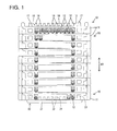
FIG. 1 is a front view showing a state where a plurality of housings are assembled and stacked in one embodiment, -
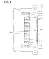
FIG. 2 is a plan view of the housing, -
FIG. 3 is a section showing a stacked state of the housings, -
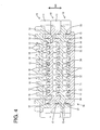
FIG. 4 is a section showing a structure for holding the housings in the stacked state, -
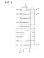
FIG. 5 is a side view showing the state where the plurality of housings are assembled and stacked, -
FIG. 6 is a front view of the housing, -
FIG. 7 is a side view of the housing, -
FIG. 8 is a front view of a retainer, -
FIG. 9 is a plan view of the retainer, -
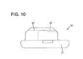
FIG. 10 is a side view of the retainer, and -
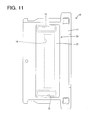
FIG. 11 is a bottom view showing a state where the retainer is mounted in the housing. - Hereinafter, one specific embodiment of the present invention is described with reference to
FIGS. 1 to 11 . A connector of this embodiment is constructed by assembling two or more (a plurality of) housings 10 (as particular first and second members) and at least one retainer 30 (as a particular second member) while stacking them one above another. A stacking direction SD of thehousings 10, an assembling direction of thehousings 10, a stacking direction of thehousings 10 and theretainer 30 and/or an assembling direction of thehousings 10 and theretainer 30 are (particularly all) vertical direction. - Each
housing 10 is made e.g. of synthetic resin and includes at least one (particularly substantially bilaterally symmetric) terminal accommodating portion 11 (as a particular base portion) as shown inFIGS. 1 ,2 ,6 and7 . Theterminal accommodating portion 11 particularly substantially is in the form of a flat block whose dimension in forward and backward directions is smaller than the width (lateral dimension) and/or larger than the height (vertical dimension). A plurality of (e.g. ten)terminal accommodating chambers 12 into which respectiveterminal fittings 20 are to be at least partly inserted (particularly substantially from behind) are formed substantially side by side in a lateral direction in theterminal accommodating portion 11 while being at least partly partitioned by partition walls. - As shown in
FIG. 4 , at least a part of the accommodating chambers 12 (particularly each of twoterminal accommodating chambers 12 on the left and right ends and twoterminal accommodating chambers 12 arranged at lateral center positions out of the plurality (e.g. of ten) terminal accommodating chambers 12) is formed with a receivingportion 13. Thereceiving portion 13 is formed on or near (particularly the opening edge of) a communication opening 14 in the lateral or lower surface of theterminal accommodating portion 11. - As shown in
FIGS. 3 ,4 and11 , the (particularly each) terminalaccommodating portion 11 is formed with the communication opening 14 making an opening in the lower surface (outer surface) and communicating with the terminal accommodating chamber(s) 12. The communication opening 14 particularly substantially has a rectangular shape long in the lateral direction so as to substantially communicate with all theterminal accommodating chambers 12. Similarly, the terminalaccommodating portion 11 is formed with one or more, particularly a pair of (particularly substantially bilaterally symmetric)positioning holes 15 making openings in the lower surface. The pair ofpositioning holes 15 particularly substantially are arranged at the opposite sides of the communication opening 14. - As shown in
FIGS. 1 ,2 and4 , each terminal accommodatingportion 11 is formed with one or more (e.g. ten)projections 16 projecting at an angle different from 0° or 180°, preferably substantially upward at right angles from the upper surface (outer surface). The (particularly ten) projection(s) 16 is/are in the form of rib(s) extending in forward and backward directions and arranged (particularly substantially side by side in the lateral direction) so as to substantially correspond to the respective terminal accommodating chamber(s) 12. The projection(s) 16 and the communication opening 14 are in such a positional relationship as to be arranged at the outer surfaces substantially opposite to each other in the vertical direction (stacking direction SD of the housings 10). Similarly, one or more, particularly a pair of (particularly substantially bilaterally symmetric)positioning projections 17 are formed to substantially correspond to the positioning hole(s) 15 on the upper surface of the terminal accommodatingportion 11. - As shown in
FIGS. 2 ,4 and6 , at least one projection 16 (particularly each of twoprojections 16 on the left and right ends and twoprojections 16 arranged at substantially lateral center positions out of the tenprojections 16 arranged in the lateral direction) is formed with a lockingportion 18 in the form of a projection. The lockingportion 18 formed on the projection on a lateral end (e.g. on the left end) projects from the lateral surface (e.g. the left surface) of theprojection 16, and the lockingportion 18 formed on theprojection 16 on the other end (e.g. the right end) projects from the other surface (e.g. the right surface) of theprojection 16. That is, the lockingportions 18 on the lateral (left and right) ends project in substantially opposite directions. Particularly, the lockingportions 18 formed on the twocenter projections 16 both project from the left surfaces (i.e. project in the same direction). As shown inFIG. 6 , each of these lockingportions 18 has a horizontal (perpendicular to the assembling direction or stacking direction SD of the housing 10) lockingsurface 18A substantially facing downward and a guidinginclined surface 18B inclined with respect to the vertical direction (assembling direction of the housing 10). - As shown in
FIG. 3 , each terminal fitting 20 particularly is a female terminal of a known form long and narrow in forward and backward directions as a whole. A (particularly substantially rectangular)tube portion 21 is formed on or near a front end side of the terminal fitting 20, and a wire connection portion (particularly comprising a wire crimping portion 22) having a height smaller than that of the (rectangular)tube portion 21 is formed on a rear end side of theterminal fitting 20. Since the upper or lateral surface of the (rectangular)tube portion 21 is substantially continuous and flush with the respective (upper) surface of the wire connection portion (particularly the wire crimping portion 22), there is a height difference between the lower surface of therectangular tube portion 21 and that of the wire connection portion (particularly the wire crimping portion 22) to form a step. Particularly due to this height difference, a retainingportion 23 is formed on a lateral or lower edge portion of a rear end portion of the (rectangular)tube portion 21. - The
retainer 30 is made e.g. of synthetic resin and, as shown inFIGS. 8 to 10 , includes abase portion 31 particularly substantially having a rectangular planar shape long in the lateral direction, one or more (e.g. ten)projections 32 projecting outward or upward from the outer or upper surface of thebase portion 31, and one or more, particularly a pair of lateral (left and/or right)positioning projections 33 projecting upward from the upper surface of thebase portion 31, thebase portion 31, the projection(s) 32 and the positioning projection(s) 33 being integrally or unitarily formed. As shown inFIG. 11 , the width of thebase portion 31 particularly is larger than the opening width of thecommunication opening 14, and/or a dimension of thebase portion 31 in forward and backward directions particularly is larger than an opening dimension of thecommunication opening 14 in forward and backward directions. As shown inFIGS. 8 to 10 , the one or more (e.g. ten)projections 32 particularly are in the same shape, form and/or arrangement as the one or more (e.g. ten)projections 16 formed on thehousing 10, particularly including the presence or absence of a lockingportion 34, the shape of the locking portion 34 (lockingsurface 34A and guidinginclined surface 34B) and the like. Further, the one or more, particularly the pair ofpositioning projections 33 particularly substantially are in the same shape and arrangement as thepositioning projections 17 of thehousing 10. - Next, functions of this embodiment are described. In assembling the
housings 10 and theretainer 30, the one or moreterminal fittings 20 are at least partly inserted into the terminalaccommodating chambers 12 of the respective housings 10 (particularly substantially from behind) in a state where thehousings 10 and theretainer 30 are separated (before thehousings 10 and theretainer 30 are stacked). When the one or moreterminal fittings 20 are inserted to proper positions in all the terminalaccommodating chambers 12, the terminalaccommodating portions 11 of thehousings 10 are assembled or stacked one above another (along the stacking direction SD) and theretainer 30 is assembled with thebottommost housing 10 in the stacking direction SD (vertical direction) by placing thebase portion 31 on the lower surface of theterminal accommodating portion 11 of thebottommost housing 10 as shown inFIGS. 1 ,3 to 5 . In assembling, the one or morerespective positioning projections housings 10 and thehousing 10 and theretainer 30 are positioned with respect to a horizontal direction (forward and backward directions and/or lateral direction). - When the
housings 10 are assembled, one or more therespective projections 16 of thelower housing 10 at least partly are inserted into the one or more terminalaccommodating chambers 12 through the communication opening(s) 14 of theupper housing 10 and engaged with the one ormore retaining portions 23 of theterminal fittings 20 at least partly inserted in the respective terminal accommodating chambers 12 (particularly substantially from behind) as shown inFIGS. 3 and4 , and the one or moreterminal fittings 20 are held and retained by this engagement action. Further, when thebottommost housing 10 and theretainer 30 are assembled, the one or morerespective projections 32 of theretainer 30 at least partly are inserted into the terminalaccommodating chambers 12 through thecommunication opening 14 of thehousing 10 and engaged with the one ormore retaining portions 23 of the respectiveterminal fittings 20 at least partly inserted in the respective terminal accommodating chambers 12 (particularly substantially from behind), and theterminal fittings 20 are held and retained by this engagement action. - If all the
terminal fittings 20 are properly inserted, the plurality ofhousings 10 and theretainer 30 are properly assembled while being stacked (along the stacking direction SD) one above another as described above. When thehousings 10 and theretainer 30 are properly assembled in this way, the lower surface of theupper housing 10 and the upper surface of thelower housing 10 particularly are held substantially in surface contact. Thus, there is no large clearance between the twohousings 10. Further, since the lower surface of thebottommost housing 10 and the upper surface of thebase portion 31 of theretainer 30 particularly are (also) held substantially in surface contact, there is no large clearance between the thishousing 10 and theretainer 30. - On the contrary, if any of the
terminal fittings 20 is insufficiently inserted without being inserted deeply enough to the proper insertion position, the rear end portion of the (rectangular)tube portion 21 is located in an entrance path for theprojection 16 as shown inFIG. 3 . Accordingly, if thelower housing 10 is assembled with thishousing 10, theprojection 16 comes in contact with (interferes with) the (particularly substantially rectangular)tube portion 21 of the insufficiently inserted terminal fitting 20 from below during the assembling operation, whereby the assembling operation of thehousings 10 is prevented on the way. If there is any insufficiently insertedterminal fitting 20 in the bottommost housing 10 (not shown), theprojection 32 of theretainer 30 interferes with the (particularly substantially rectangular)tube portion 21 during an assembling operation of theretainer 30, wherefore the assembling operation of thehousing 10 and theretainer 30 is prevented on the way. - With the assembling operation of the
housings 10 and/or that of thehousing 10 and theretainer 30 prevented due to the presence of the insufficiently insertedterminal fitting 20 in this way, aclearance 40 which is open in the horizontal direction (direction crossing the assembling direction) is formed between the terminalaccommodating portions 11 of thehousings 10 and/or between the terminal accommodatingportion 11 of thehousing 10 and thebase portion 31 of theretainer 30. Since the lockingportions portions 13 are not engaged between thehousings 10 or between thehousing 10 and theretainer 30 substantially vertically facing each other with thisclearance 40 therebetween, thehousings 10 and/or thehousing 10 and theretainer 30 having theclearance 40 formed therebetween are vertically separable. - After an assembling process of all the
housings 10 and theretainer 30 is finished, one or more detection jigs 41 are brought closer to the connector from front to detect an assembled state. Since there is no clearance between thehousings 10 and between thehousing 10 and theretainer 30 if all thehousings 10 and theretainer 30 are properly assembled, the detection jigs 41 come into contact with the front end surfaces of thehousings 10. In this way, it can be found that all theterminal fittings 20 are properly inserted and the assembling operation of thehousings 10 and that of thehousing 10 and theretainer 30 have been properly performed. - On the contrary, if there is any insufficiently inserted
terminal fitting 20 or if the assembling operation of thehousings 10 or that of thehousing 10 and theretainer 30 has not been properly performed although all theterminal fittings 20 are properly inserted, theclearance 40 is formed between thehousings 10 or between thehousing 10 and theretainer 30 as shown inFIG. 3 . In this case, thedetection jig 41 at least partly enters thisclearance 40, wherefore it can be found that at least any one of the insertion of theterminal fittings 20, the assembling operation of thehousings 10 and the assembling operation of thehousing 10 and theretainer 30 has not been properly performed. - As described above, each
housing 10 constituting or forming part of the connector of this embodiment includes the one or more terminalaccommodating chambers 12, thecommunication opening 14 formed in the outer surface and communicating with the terminal accommodating chamber(s) 12 and the one ormore projections 16 projecting from theterminal accommodating portion 11, and/or theretainer 30 constituting or forming part of the connector includes thebase portion 31 and theprojections 32 projecting from thebase portion 31. Eachhousing 10 includes the one ormore receiving portions 13 and the one ormore locking portions 18 and/or theretainer 30 includes the one ormore locking portions 34. According to this construction, when thehousings 10 are assembled, the receiving portion(s) 13 of theupper housing 10 and the locking portion(s) 18 of thelower housing 10 are engaged to hold thehousings 10 in the assembled state. Further, when thehousing 10 and theretainer 30 are assembled, the receiving portion(s) 13 of thehousing 10 and the locking portion(s) 34 of the retainingportion 30 are engaged to hold thehousing 10 and theretainer 30 in the assembled state. Thus, the operator needs not hold thehousings 10 and theretainer 30 by the hand to prevent separation after thehousings 10 and theretainer 30 are stacked and assembled, and operability is excellent. - Accordingly, to improve operability, the (particularly each) housing 10 (first member, second member) includes one or more terminal
accommodating chambers 12, at least onecommunication opening 14 formed in an outer surface and communicating with the terminal accommodating chamber(s) 12, and one ormore projections 16 projecting from a terminal accommodating portion 11 (base portion). With thehousings 10 placed or stacked one above the other, the projection(s) 16 inserted in the terminal accommodating chamber(s) 12 through the communication opening(s) 14 is/are engaged with terminal fitting(s) 20 in the terminal accommodating chamber(s) 12 to retain the terminal fitting(s) 20. One ormore receiving portions 13 are provided in the (particularly each)housing 10 and the (particularly each)projection 16 particularly includes a lockingportion 18 to be engaged with the corresponding receivingportion 13 to hold thehousings 10 in an assembled state. - The present invention is not limited to the above described and illustrated embodiment. For example, the following embodiments are also included in the technical scope of the present invention.
- (1) Although the first and second members are the mutually identical housings in the above embodiment, they may be different members. That is, the present invention can be applied also when the first member is a housing as an exclusive means for accommodating the terminal fittings and the second member is a retainer as an exclusive means for retaining the terminal fittings in the first member.
- (2) In the above embodiment, a clearance is formed between the first and second members only when the first member (housing) and the second member (housing or retainer) are incompletely assembled. However, a clearance narrower than that at the time of incomplete assembling may be formed even when the two members (housings or housing and retainer) are properly assembled.
- (3) In the above embodiment, a clearance is formed between the first member (housing) and the second member (housing or retainer) when the two members are incompletely assembled. However, no clearance member may be formed between the two members when the two members are incompletely assembled.
- (4) Although the number of the projections is set at ten in the above embodiment, it may be any number e.g. nine or smaller or eleven or larger.
- (5) Although the locking portion is formed on either the left or right surface of the projection in the above embodiment, it may be formed on the front or rear surface of the projection.
- (6) Although one locking portion is formed on one projection in the above embodiment, a plurality of locking portions may be formed on one projection.
- (7) Although the locking portions are formed on the projections located on the left and right ends and on the two projections located in the center, the locking portions may be formed on the projections arranged at positions other than the above ones.
- (8) Although the locking portions are in the form of projections in the above embodiment, they may be in the form of recesses formed in the outer surfaces of the projections.
- (9) Although the above embodiment has been described with respect to a housing in which one or more female terminal fittings are to be accommodated, it should be understood that the invention is equally applicable to a housing in which one or more male terminal fittings are to be accommodated.
-
- 10
- ... housing (first member, second member)
- 11
- ... terminal accommodating portion (base portion)
- 12
- ... terminal accommodating chamber
- 13
- ... receiving portion
- 14
- ... communication opening
- 16
- ... projection
- 18
- ... locking portion
- 20
- ... terminal fitting
- 30
- ... retainer (second member)
- 31
- ... base portion
- 32
- ... projection
- 34
- ... locking portion
- 40
- ... clearance
Claims (15)
- A connector, comprising:a first member (10) including at least one terminal accommodating chamber (12) and at least one communication opening (14) formed in an outer surface and communicating with the terminal accommodating chamber (12); anda second member (10; 30) including at least one projection (16) projecting from a base portion (11);wherein:the projection (16; 32) at least partly inserted in the terminal accommodating chamber (12) through the communication opening (14) is to be engaged with a terminal fitting (20) at least partly accommodated in the terminal accommodating chamber (12) to retain the terminal fitting (20) in a state where the second member (10; 30) is assembled by placing the base portion (11) on the outer surface of the first member (10);the first member (10) includes at least one receiving portion (13); andthe projection (16; 32) includes at least one locking portion (18) for holding the first and second members (10; 30) in an assembled state by being engaged with the receiving portion (13).
- A connector according to claim 1, wherein the first and second members (10) are mutually identical housings.
- A connector according to claim 2, wherein the or each housing (10) includes the terminal accommodating chamber (12), the communication opening (14), the projection (16), the receiving portion (13) and the locking portion (18).
- A connector according to any one of the preceding claims, wherein:the projection (16; 32) interferes with the terminal fitting (20) to make the assembling of the first and second members (10; 30) incomplete when the terminal fitting (20) is located at an improper accommodation position in the terminal accommodating chamber (12).
- A connector according to any one of the preceding claims, wherein:a clearance (40) which is open in a direction crossing an assembling direction is formed between the first and second members (10; 30) when the terminal fitting (20) is located at an improper accommodation position in the terminal accommodating chamber (12).
- A connector according to any one of the preceding claims, wherein when the first and second members (10; 30) are properly assembled, one surface of the first member (10) and a substantially facing surface of the second member (10; 30) are held substantially in surface contact.
- A connector according to any one of the preceding claims, wherein the terminal fitting (20) is improperly inserted in the terminal accommodating chamber (12), a portion (21) of the terminal fitting (20) is located in an entrance path for the projection (16; 32).
- A connector according to any one of the preceding claims, wherein a plurality of housing (10) and a retainer (30) are stacked in a stacking direction (SD) as the first and second members (10; 30).
- A method of assembling a connector, comprising the following steps:providing a first member (10) including at least one terminal accommodating chamber (12) and at least one communication opening (14) formed in an outer surface and communicating with the terminal accommodating chamber (12); andarranging a second member (10; 30) including at least one projection (16; 32) projecting from a base portion (11) on the first member (10) such that the projection (16; 32) is at least partly inserted in the terminal accommodating chamber (12) through the communication opening (14) and is engaged with a terminal fitting (20) at least partly accommodated in the terminal accommodating chamber (12) to retain the terminal fitting (20) in a state where the second member (10; 30) is assembled by placing the base portion (11) on the outer surface of the first member (10); andholding the first and second members (10; 30) in an assembled state by engaging at least one receiving portion (13) of the first member (10) with at least one locking portion (18) of the projection (16; 32).
- A method according to claim 9, wherein the first and second members (10) are mutually identical housings.
- A method according to claim 10, wherein the or each housing (10) includes the terminal accommodating chamber (12), the communication opening (14), the projection (16), the receiving portion (13) and the locking portion (18).
- A method according to any one of the preceding claims 9 to 11, wherein:the projection (16; 32) interferes with the terminal fitting (20) to make the assembling of the first and second members (10; 30) incomplete when the terminal fitting (20) is located at an improper accommodation position in the terminal accommodating chamber (12).
- A method according to any one of the preceding claims 9 to 12, wherein:a clearance (40) which is open in a direction crossing an assembling direction is formed between the first and second members (10; 30) when the terminal fitting (20) is located at an improper accommodation position in the terminal accommodating chamber (12).
- A method according to claim 13, wherein the improper assembling is detected by at least partly inserting a jig (41) into the clearance (40).
- A method according to any one of the preceding claims 9 to 14, wherein a plurality of housing (10) and a retainer (30) are stacked in a stacking direction (SD) as the first and second members (10; 30).
Applications Claiming Priority (1)
| Application Number | Priority Date | Filing Date | Title |
|---|---|---|---|
| JP2011048048A JP5637015B2 (en) | 2011-03-04 | 2011-03-04 | connector |
Publications (1)
| Publication Number | Publication Date |
|---|---|
| EP2495821A1 true EP2495821A1 (en) | 2012-09-05 |
Family
ID=45654927
Family Applications (1)
| Application Number | Title | Priority Date | Filing Date |
|---|---|---|---|
| EP12000845A Withdrawn EP2495821A1 (en) | 2011-03-04 | 2012-02-09 | Connector and assembling method therefor |
Country Status (4)
| Country | Link |
|---|---|
| US (1) | US8747168B2 (en) |
| EP (1) | EP2495821A1 (en) |
| JP (1) | JP5637015B2 (en) |
| CN (1) | CN102655299B (en) |
Families Citing this family (19)
| Publication number | Priority date | Publication date | Assignee | Title |
|---|---|---|---|---|
| JP5637015B2 (en) * | 2011-03-04 | 2014-12-10 | 住友電装株式会社 | connector |
| JP5707252B2 (en) * | 2011-06-24 | 2015-04-22 | 矢崎総業株式会社 | connector |
| DE102012100815B3 (en) * | 2012-02-01 | 2013-01-24 | Harting Electric Gmbh & Co. Kg | Electrical coupling element |
| JP2013168301A (en) * | 2012-02-16 | 2013-08-29 | Yazaki Corp | Joint connector |
| JP5730842B2 (en) * | 2012-12-05 | 2015-06-10 | 古河電気工業株式会社 | Joint connector |
| US9214763B2 (en) * | 2013-01-18 | 2015-12-15 | Delta Electronics, Inc. | Fly line connector |
| US9246286B2 (en) * | 2013-09-25 | 2016-01-26 | Virginia Panel Corporation | High speed data module for high life cycle interconnect device |
| US9362638B2 (en) * | 2014-09-03 | 2016-06-07 | Amphenol Corporation | Overmolded contact wafer and connector |
| US11031724B2 (en) * | 2017-03-09 | 2021-06-08 | Sumitomo Wiring Systems, Ltd. | Stacked connector and wire harness |
| JP6769353B2 (en) * | 2017-03-13 | 2020-10-14 | 株式会社オートネットワーク技術研究所 | Terminal unit and connector |
| DE102017111813A1 (en) * | 2017-05-30 | 2018-12-06 | Te Connectivity Germany Gmbh | Contact housing, contact housing receptacle and electrical connector |
| JP6874625B2 (en) * | 2017-09-29 | 2021-05-19 | 住友電装株式会社 | connector |
| JP7042420B2 (en) * | 2018-10-24 | 2022-03-28 | 住友電装株式会社 | Laminated connector |
| JP7549957B2 (en) * | 2019-11-22 | 2024-09-12 | スリーエム イノベイティブ プロパティズ カンパニー | Wafer Connectors and Mating Connectors |
| JP7414635B2 (en) * | 2020-05-07 | 2024-01-16 | 日本航空電子工業株式会社 | connector assembly |
| DE102020210760A1 (en) * | 2020-08-25 | 2022-03-03 | Te Connectivity Germany Gmbh | Connector with a position securing element with a contact |
| JP7522668B2 (en) * | 2021-01-07 | 2024-07-25 | 日本航空電子工業株式会社 | connector |
| JP7726610B2 (en) * | 2021-02-04 | 2025-08-20 | TE Connectivity Japan合同会社 | Electrical connector and electrical connector laminate |
| JP7784048B2 (en) * | 2022-05-31 | 2025-12-11 | 株式会社オートネットワーク技術研究所 | Stacked Connector |
Citations (5)
| Publication number | Priority date | Publication date | Assignee | Title |
|---|---|---|---|---|
| US4753614A (en) * | 1983-07-27 | 1988-06-28 | Dr. Ing. H.C.F. Porsche Aktiengesellschaft | Connecting system for electrical jacks |
| FR2706688A1 (en) * | 1993-06-16 | 1994-12-23 | Cinch Connecteurs Sa | Modular element intended, together with other identical elements, to make up an electrical connector housing element |
| JP2005032586A (en) * | 2003-07-07 | 2005-02-03 | Furukawa Electric Co Ltd:The | Multilayer connector |
| JP2009054472A (en) | 2007-08-28 | 2009-03-12 | Sumitomo Wiring Syst Ltd | Joint connector |
| WO2009148027A1 (en) * | 2008-06-02 | 2009-12-10 | 三菱電線工業株式会社 | Electric connector |
Family Cites Families (29)
| Publication number | Priority date | Publication date | Assignee | Title |
|---|---|---|---|---|
| US4707043A (en) * | 1986-11-03 | 1987-11-17 | Reed Charlie C | Electrical connector |
| DE3938964A1 (en) * | 1988-11-24 | 1990-05-31 | Yazaki Corp | MULTIPLE LEVEL CONNECTOR |
| US5156556A (en) * | 1991-03-13 | 1992-10-20 | Ma Hsi K | Office automation unit |
| FR2680285B3 (en) * | 1991-08-08 | 1995-11-17 | Max Hoffner | QUICK WIRING SYSTEM WITHOUT TOOLING OF LOW VOLTAGE LIGHTING INSTALLATIONS. |
| JP2555733Y2 (en) * | 1991-12-25 | 1997-11-26 | 住友電装株式会社 | connector |
| JP2518968Y2 (en) * | 1992-02-06 | 1996-12-04 | 矢崎総業株式会社 | Combined connector |
| JP2601493Y2 (en) * | 1993-05-21 | 1999-11-22 | 矢崎総業株式会社 | connector |
| JP3320986B2 (en) * | 1996-08-27 | 2002-09-03 | 矢崎総業株式会社 | Coupling connector |
| JP3530046B2 (en) * | 1998-11-13 | 2004-05-24 | 矢崎総業株式会社 | Joint connector |
| JP4205240B2 (en) * | 1999-03-01 | 2009-01-07 | 矢崎総業株式会社 | Splice absorption structure |
| JP3701495B2 (en) * | 1999-03-03 | 2005-09-28 | 矢崎総業株式会社 | Splice absorption connector |
| JP3494917B2 (en) * | 1999-03-31 | 2004-02-09 | 矢崎総業株式会社 | ID connector |
| JP3459375B2 (en) * | 1999-04-06 | 2003-10-20 | 矢崎総業株式会社 | Crimp joint connector |
| JP3598908B2 (en) * | 1999-09-28 | 2004-12-08 | 住友電装株式会社 | Terminals and joint connectors |
| US6361374B1 (en) * | 2000-02-29 | 2002-03-26 | Molex Incorporated | Connector module retainer especially suitable for wafer connectors and connector assembly utilizing same |
| JP3638840B2 (en) * | 1999-12-02 | 2005-04-13 | 矢崎総業株式会社 | Connector connection method |
| JP3899217B2 (en) * | 2000-03-14 | 2007-03-28 | 矢崎総業株式会社 | Wire harness and method for manufacturing wire harness |
| US6478632B2 (en) * | 2000-04-28 | 2002-11-12 | Sumitomo Wiring Systems, Ltd. | Shake preventing construction for a terminal fitting and a connector |
| JP2002025723A (en) * | 2000-07-10 | 2002-01-25 | Sumitomo Wiring Syst Ltd | Joint connector |
| JP2002033154A (en) * | 2000-07-17 | 2002-01-31 | Yazaki Corp | Joint connector |
| JP3846624B2 (en) * | 2001-10-16 | 2006-11-15 | 住友電装株式会社 | Joint connector |
| US6802746B2 (en) * | 2002-12-11 | 2004-10-12 | Molex Incorporated | Electrical connector with terminal position assurance system |
| JP4508098B2 (en) * | 2005-12-20 | 2010-07-21 | 住友電装株式会社 | connector |
| US7494384B2 (en) * | 2007-04-10 | 2009-02-24 | Deutsch Engineered Connecting Devices, Inc. | Modular interconnect system and apparatus |
| EP2023445B1 (en) * | 2007-08-10 | 2012-07-25 | Sumitomo Wiring Systems, Ltd. | A joint connector and an assembling method therefor |
| JP4978788B2 (en) * | 2007-08-10 | 2012-07-18 | 住友電装株式会社 | Joint connector |
| TW200910701A (en) * | 2007-08-22 | 2009-03-01 | Delta Electronics Inc | Stacked combination connector and connector assembly |
| JP5189860B2 (en) * | 2008-03-05 | 2013-04-24 | 矢崎総業株式会社 | Combined connector |
| JP5637015B2 (en) * | 2011-03-04 | 2014-12-10 | 住友電装株式会社 | connector |
-
2011
- 2011-03-04 JP JP2011048048A patent/JP5637015B2/en not_active Expired - Fee Related
-
2012
- 2012-02-09 EP EP12000845A patent/EP2495821A1/en not_active Withdrawn
- 2012-02-24 CN CN201210045173.6A patent/CN102655299B/en not_active Expired - Fee Related
- 2012-02-27 US US13/405,671 patent/US8747168B2/en not_active Expired - Fee Related
Patent Citations (5)
| Publication number | Priority date | Publication date | Assignee | Title |
|---|---|---|---|---|
| US4753614A (en) * | 1983-07-27 | 1988-06-28 | Dr. Ing. H.C.F. Porsche Aktiengesellschaft | Connecting system for electrical jacks |
| FR2706688A1 (en) * | 1993-06-16 | 1994-12-23 | Cinch Connecteurs Sa | Modular element intended, together with other identical elements, to make up an electrical connector housing element |
| JP2005032586A (en) * | 2003-07-07 | 2005-02-03 | Furukawa Electric Co Ltd:The | Multilayer connector |
| JP2009054472A (en) | 2007-08-28 | 2009-03-12 | Sumitomo Wiring Syst Ltd | Joint connector |
| WO2009148027A1 (en) * | 2008-06-02 | 2009-12-10 | 三菱電線工業株式会社 | Electric connector |
Also Published As
| Publication number | Publication date |
|---|---|
| CN102655299A (en) | 2012-09-05 |
| JP5637015B2 (en) | 2014-12-10 |
| CN102655299B (en) | 2015-04-01 |
| US20120225576A1 (en) | 2012-09-06 |
| JP2012186001A (en) | 2012-09-27 |
| US8747168B2 (en) | 2014-06-10 |
Similar Documents
| Publication | Publication Date | Title |
|---|---|---|
| US8747168B2 (en) | Stacking connector | |
| US8147261B2 (en) | Connector | |
| EP1816709B1 (en) | A connector, a connector assembly and a method of assembling a connector | |
| EP1990869B1 (en) | A connector and assembling method thereof | |
| JP4978788B2 (en) | Joint connector | |
| US9515411B2 (en) | Connector with lever | |
| US7488221B2 (en) | Connector | |
| US9997867B2 (en) | Connector | |
| CN104541412A (en) | Connector | |
| EP3631907B1 (en) | Modular electrical connector | |
| WO2018037904A1 (en) | Twisted pair wire joint connector | |
| EP1303009B1 (en) | A cover, a joint connector and a method for mounting a joint connector | |
| US9972921B2 (en) | Connector with sub-housing and uniting portion | |
| US11088488B2 (en) | Connector with one-sided dovetail projections | |
| US9812807B2 (en) | Connector | |
| US10033129B2 (en) | Connector | |
| US7695325B2 (en) | Connector | |
| US6702628B2 (en) | Connector and a method of assembling it | |
| JP5012325B2 (en) | Joint connector | |
| JP2001203026A (en) | Assembling method of housing and multi-stage connector | |
| EP1936748B1 (en) | A connector and a method of forming it | |
| US9478890B2 (en) | Connector and inspection tool | |
| US10050388B2 (en) | Connector having a shorting terminal with a pair of press-fit projections | |
| JP2000067980A (en) | Connector with secondary locking member and housing assembly used therefor | |
| JP2022185272A (en) | connector |
Legal Events
| Date | Code | Title | Description |
|---|---|---|---|
| PUAI | Public reference made under article 153(3) epc to a published international application that has entered the european phase |
Free format text: ORIGINAL CODE: 0009012 |
|
| AK | Designated contracting states |
Kind code of ref document: A1 Designated state(s): AL AT BE BG CH CY CZ DE DK EE ES FI FR GB GR HR HU IE IS IT LI LT LU LV MC MK MT NL NO PL PT RO RS SE SI SK SM TR |
|
| AX | Request for extension of the european patent |
Extension state: BA ME |
|
| 17P | Request for examination filed |
Effective date: 20120927 |
|
| 17Q | First examination report despatched |
Effective date: 20140717 |
|
| GRAP | Despatch of communication of intention to grant a patent |
Free format text: ORIGINAL CODE: EPIDOSNIGR1 |
|
| RIC1 | Information provided on ipc code assigned before grant |
Ipc: H01R 13/641 20060101ALI20170727BHEP Ipc: H01R 13/436 20060101AFI20170727BHEP Ipc: H01R 13/514 20060101ALI20170727BHEP Ipc: H01R 13/506 20060101ALI20170727BHEP Ipc: H01R 43/20 20060101ALN20170727BHEP |
|
| INTG | Intention to grant announced |
Effective date: 20170821 |
|
| STAA | Information on the status of an ep patent application or granted ep patent |
Free format text: STATUS: THE APPLICATION IS DEEMED TO BE WITHDRAWN |
|
| 18D | Application deemed to be withdrawn |
Effective date: 20180103 |