EP2495584B1 - Communication processing apparatus and distance measuring method for communication processing apparatus - Google Patents
Communication processing apparatus and distance measuring method for communication processing apparatus Download PDFInfo
- Publication number
- EP2495584B1 EP2495584B1 EP11188980.4A EP11188980A EP2495584B1 EP 2495584 B1 EP2495584 B1 EP 2495584B1 EP 11188980 A EP11188980 A EP 11188980A EP 2495584 B1 EP2495584 B1 EP 2495584B1
- Authority
- EP
- European Patent Office
- Prior art keywords
- phase
- tag
- wave
- reflected wave
- distance
- Prior art date
- Legal status (The legal status is an assumption and is not a legal conclusion. Google has not performed a legal analysis and makes no representation as to the accuracy of the status listed.)
- Active
Links
- 238000012545 processing Methods 0.000 title claims description 98
- 238000004891 communication Methods 0.000 title claims description 47
- 238000000034 method Methods 0.000 title claims description 23
- 238000001514 detection method Methods 0.000 claims description 17
- 230000005540 biological transmission Effects 0.000 claims description 16
- 238000004364 calculation method Methods 0.000 description 12
- 238000010586 diagram Methods 0.000 description 3
- 239000013598 vector Substances 0.000 description 3
- 239000002131 composite material Substances 0.000 description 2
- 230000010365 information processing Effects 0.000 description 2
- 239000006096 absorbing agent Substances 0.000 description 1
- 238000006243 chemical reaction Methods 0.000 description 1
- 230000002542 deteriorative effect Effects 0.000 description 1
- 230000000694 effects Effects 0.000 description 1
- 238000004519 manufacturing process Methods 0.000 description 1
- 238000005259 measurement Methods 0.000 description 1
- 230000010355 oscillation Effects 0.000 description 1
- 238000010183 spectrum analysis Methods 0.000 description 1
Images

Classifications
-
- G—PHYSICS
- G01—MEASURING; TESTING
- G01S—RADIO DIRECTION-FINDING; RADIO NAVIGATION; DETERMINING DISTANCE OR VELOCITY BY USE OF RADIO WAVES; LOCATING OR PRESENCE-DETECTING BY USE OF THE REFLECTION OR RERADIATION OF RADIO WAVES; ANALOGOUS ARRANGEMENTS USING OTHER WAVES
- G01S13/00—Systems using the reflection or reradiation of radio waves, e.g. radar systems; Analogous systems using reflection or reradiation of waves whose nature or wavelength is irrelevant or unspecified
- G01S13/74—Systems using reradiation of radio waves, e.g. secondary radar systems; Analogous systems
- G01S13/82—Systems using reradiation of radio waves, e.g. secondary radar systems; Analogous systems wherein continuous-type signals are transmitted
Definitions
- the present invention relates to a communication processing apparatus for communicating with an RFID tag using a continuous carrier wave, and more particularly relates to a technique for measuring a distance between a communication processing apparatus and an RFID tag (hereinafter, may be simply referred to as "tag") transmitting a response in reply to a command given by the communication processing apparatus.
- tag a technique for measuring a distance between a communication processing apparatus and an RFID tag
- the communication processing apparatus alternately performs processing for transmitting a command to a tag by modulating a carrier wave while continuously transmitting the carrier wave at a constant frequency and processing for receiving a response from the tag by transmitting an unmodulated carrier wave (Continuous Wave; abbreviated as CW).
- CW Continuous Wave
- the tag having received the command responds to the command by changing the impedance of the circuit of the tag.
- a signal (reflected wave) carrying the response signal in reply to the command onto the unmodulated carrier wave is transmitted back to the communication processing apparatus, and then the response signal is decoded.
- the radio wave may reach a location beyond the necessary distance.
- the radio wave may be reflected by floors and walls at the site, and may be guided to a tag far away.
- the tag residing at the location not requiring communication may respond to the command, and may cause a problem in information processing.
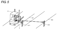
- a specific example is shown in Fig. 5 .
- antennas A1, A2 of communication processing apparatuses are provided at a side of parallel paths B1, B2, respectively, and information is read out from a tag T attached to a vehicle C traveling along the paths B1, B2 using these antennas A1, A2.
- the antenna A1 corresponding to the path B1 in which the vehicle C is located should be allowed to communicate with the tag T, but the radio waves transmitted from the antenna A2 in the adjacent path B2 also reach the tag T.
- the tag T responds to the command transmitted from the antenna A2, and incorrect information may be read and written.
- a method for estimating a distance from an antenna to a tag based on a strength of a response signal from the tag and a method for measuring a distance to a tag using a time length from when a command is transmitted to when a response from the tag is received (e.g., see Japanese Patent No. 4462149 and Japanese Unexamined Patent Publication No. 2008-232907 ).
- the method for estimating a distance to a tag based on a strength of a response wave is useful when the strength of reflection of the tag is constant and the radio wave is less likely to be reflected by the floors and walls. In reality, however, the strength of reflection of the tag varies according to difference in the attachment state of the tag and the directional pattern. Unless special equipment such as an electromagnetic wave absorber is provided, it is difficult to prevent reflection of the radio waves on the floors and the walls.
- Patent Document 3 makes use of a principle of a phase difference occurring between the carrier wave transmitted to the tag and the reflected wave transmitted from the tag in accordance with the distance to the tag and the frequency of the carrier wave.
- it is necessary to increase the difference of frequencies of the two kinds of carrier waves as much as possible, but due to the limitation of the radio wave method, it is impossible to greatly change the frequencies.
- WO 02/088776 A2 discloses a hybrid tag device, a hybrid tag protocol, a methodology and a hybrid system for tracking assets.
- the hybrid tag device comprises a beacon transmitter that transmits a narrow band signal, such as a UHF signal, and a wide band transmitter that transmits a wide band signal that is used to determine a distance from the hybrid tag device to a hybrid tag reader.
- the hybrid tag device may also comprise a wide band signal receiver to receive a wide band signal transmitted by the hybrid tag reader, which in response thereto transmits the wide band signal.
- the hybrid system may comprise a sign post device that transmits an interrogation signal to the hybrid tag device to enable the hybrid tag device to transmit the narrow band signal.
- US 2010/0076722 A1 discloses a distance measuring apparatus comprising a transmitter, configured to transmit first one-frame signals from an antenna via radio waves having three or more different carrier frequencies, each of the first one-frame signals being composed of a request signal and a continuous carrier wave; a receiver, configured to receive second one-frame signals generated when the first one-frame signals are reflected by a reflector while being modulated, each of the second one-frame signals having a frequency corresponding to a frequency of an associated one of the first one-frame signals; a phase information acquirer, configured to calculate a phase change amount between the first one-frame signals and the second one-frame signals for each of the carrier frequencies; and a distance calculator, configured to calculate a distance between the antenna and the reflector by high-resolution spectrum analysis, on the basis of the carrier frequencies and the phase change amount calculated for each of the carrier frequencies.
- an object of the present invention is to accurately measure the distance to the tag without deteriorating the efficiency of communication processing.
- the phase of the continuous carrier wave is changed when the communication processing apparatus receives the reflected wave from the tag in a period in which the continuous carrier wave is transmitted in order to receive a response from the tag after the command is received. Then, a time is measured from when the phase is changed to when the same change of the phase is detected in the reflected wave received from the tag. The time taken for the radio wave to go from the communication processing apparatus to the tag and from the tag to the communication processing apparatus can be calculated from the measured time. Therefore, the distance to the tag can be measured accurately.
- the phase change unit changes the phase of the continuous carrier wave in response to detection of a preamble in the response information in the decoding processing.
- the preamble in the response signal is configured to have bit signals of "1" and "0" arranged in a certain pattern. Therefore, by detecting the pattern, start of reception of the reflected wave can be easily determined, and the phase can be switched. In addition, noise reflected wave reflected by floors and walls and returning back to the communication processing apparatus is prevented from being falsely recognized as a reflected wave from the tag.
- the phase change unit changes the phase of the continuous carrier wave in response to detection of a preamble in the response signal in the decoding processing, and the phase detection unit detects change of the phase of the reflected wave transmitted in reply to the continuous carrier wave while the preamble is detected.
- the measuring processing of the distance can be finished while receiving the reflected wave including signals arranged in a certain pattern. Therefore, the distance can be reliably measured within one cycle of communication processing.
- a communication processing apparatus further includes a determining unit for determining whether or not the RFID tag that returned the reflected wave is appropriate as a target of communication based on the distance measured by the distance measuring unit. In this manner, it is easy to employ only the response signals transmitted from the tags within the range of the defined distance, and this prevents false information processing from being carried out.
- a preferred mode of a communication processing apparatus is an RFID reader/writer for reading and writing information to/from the RFID tag.
- the preferred mode is not limited thereto, and it may be configured as an RFID reader for only reading information.
- the phase of the continuous carrier wave is changed in response to start of reception of the reflected wave from the RFID tag in reply to the command, and the distance to the tag is measured using a length of a time from when the continuous carrier wave is changed to when the same change of the phase occurs in the reflected wave. Therefore, the distance can be measured without being affected by variations of reflection strength and response time of the tag in reply to the command.
- the measured time increases according to the reflection during the propagation, and accordingly, the measured value of the distance becomes a large value. This enables measurement that is less likely to be affected by the reflections from the floors and the like.
- Fig. 1 is a block diagram illustrating a configuration of a reader/writer which is an example of a communication processing apparatus to which the present invention is applied.
- a reader/writer 1 communicates with a passive-type or semi-passive-type RFID tag 2 using UHF band radio wave, reads information from this tag 2, and write information to the tag 2.
- the reader/writer 1 includes a transmission/reception circuit 100 including an antenna 10 and a control unit 110 for controlling operation of the transmission/reception circuit.
- the used radio wave is not limited to the UHF band. Radio waves in other bands may also be used.
- the transmission/reception circuit 100 includes not only an antenna 10 but also a circulator 11, an oscillator 12, a modulation circuit 13, distributors 14, 15, mixers 16A, 16B, a 90 degrees phase shifter 17, amplifiers 18A, 18B, A/D converters 19A, 19B, and the like.
- the control unit 110 is actually a program logic circuit (FPGA), and is provided with functions of a transmission control unit 111, a phase detection unit 112, a distance calculation unit 113, a decoding processing unit 114, and an output processing unit 115.
- FPGA program logic circuit
- the reader/writer 1 is provided with an interface circuit for a host device (not shown).
- the control unit 110 carries out communication processing with a tag based on an instruction transmitted from a host device, and transmits a processing result to the host device.
- the oscillator 12 outputs a frequency signal serving as a basis of a carrier wave.
- the modulation circuit 13 receives a data signal provided by the transmission control unit 111, and modulates a continuous carrier with the data signal.
- the modulated signal is guided to the antenna 10 via the circulator 11, and transmitted as an electromagnetic wave.
- unmodulated wave (hereinafter referred to as "unmodulated wave") is transmitted.
- the modulation circuit 13 includes a phase switching circuit for shifting the phase of the carrier wave. This circuit is activated in response to a phase switching command provided by the transmission control unit 111, and thereby the phase of the carrier wave is switched.
- the modulation circuit 13 is constituted by an orthogonal modulation device, and the carrier wave phase is shifted by 90 degrees.
- the configuration of the modulation circuit 13 is not limited thereto.
- the reflected wave received with the antenna 10 from the tag 2 is guided via the circulator 11 to the distributor 15, and is distributed to each of the mixers 16A, 16B.
- the distributor 14 distributes the oscillation signal provided by the oscillator 12.
- One of the distributed signals is directly input to the mixer 16A, and the other of the signals is input to the mixer 16B via the 90 degrees phase shifter 17.
- the mixer 16A outputs an I signal included in the reflected wave
- the mixer 16B outputs a Q signal included in the reflected wave.
- the I signal and the Q signal are respectively amplified by the amplifiers 18A, 18B, thereafter digitally converted by A/D conversion circuits 19A, 19B, and input to the control unit 110.
- the I signal and the Q signal received by the control unit 110 is processed by the phase detection unit 112 and the decoding processing unit 114.
- the phase detection unit 112 uses the I signal and the Q signal to detect change of the phase of the reflected wave. For example, this detection processing is carried out by calculation processing for obtaining a strength ratio Q/I of the Q signal with respect to the I signal and processing for comparing each calculation result with a previous calculation result.
- the decoding processing unit 114 adopts the I signal and the Q signal as vectors on an IQ plane and obtains a length of a composite vector of these vectors. Then, based on time-series change of a length thereof, the decoding processing unit 114 decodes a response signal from the tag included in the reflected wave.
- the transmission control unit 111 After the transmission control unit 111 outputs the data signal constituting the command, the transmission control unit 111 transmits a continuous wave. Further, the transmission control unit 111 outputs a phase switching command to the modulation circuit 13 in response to start of decoding of the response signal by the decoding processing unit 114. With these processings, the electromagnetic wave transmitted from the antenna 10 changes from the carrier wave carrying the command to the unmodulated wave (CW), and further changes to an unmodulated wave whose phase is shifted by 90 degrees.
- CW unmodulated wave
- the distance calculation unit 113 starts timer processing in response to output of the phase switching command, and measures the time until the phase detection unit 112 detects the same change in the phase of the reflected wave as that occurred in the unmodulated wave. Then, using the measured time, the distance from the antenna 10 to the tag 2 is calculated by executing calculation described below.
- the output processing unit 115 compares the distance calculated by the distance calculation unit 113 with a reference distance transmitted from a host device in advance, and transmits, to the host device, a response signal transmitted from a tag whose distance is calculated as a distance within the reference distance.
- the decoding processing unit 114 determines that the communicating tag is not appropriate as a target of communication, and stops decoding processing.
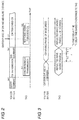
- Fig. 2 illustrates, along a time axis, a flow of communication processing carried out between the reader/writer 1 and the tag 2.
- the reader/writer 1 alternately carries out a period in which a carrier wave carrying a command is transmitted and a period in which a response from the tag 2 is received while transmitting an unmodulated wave (CW).
- the processing for measuring the distance to the tag 2 is also carried out during the period in which the unmodulated wave is transmitted.
- the reader/writer 1 transmits a detection command (query command) to all the tags 2 included in the communication range ((a) in Fig. 2 ).
- the tag 2 having received the command generates a random number, and transmits the random number to the reader/writer 1 ((b) in Fig. 2 ).
- the reader/writer 1 having received the random number recognizes the number of tags within the communication range based on the number of receptions.
- the reader/writer 1 sequentially executes, for each tag, processing for identifying a tag with which the reader/writer communicates based on the received random number and transmitting a command (Ack command) for requesting reading of information, and processing for receiving a response signal from the tag in reply to the command ((c) (d) in Fig. 2 ). While the response signal in reply to the Ack command is received, processing for switching the phase of the unmodulated wave and measuring processing of the distance are carried out ((e) in Fig. 2 ).
- Fig. 3 schematically illustrates a relationship between the phase of the unmodulated wave and the phase of the reflected wave transmitted from the tag 2. Where the phase of the initially transmitted unmodulated wave (in synchronization with the frequency signal provided by the oscillator 12) is 0 degrees, the phase of the unmodulated wave is 90 degrees after the phase is switched.
- the reflected wave transmitted from the tag 2 in reply to the unmodulated wave transmitted from the antenna 10 returns back to the antenna 10 after a predetermined period of time has passed since the transmission. However, at this time, the phase of the reflected wave is shifted according to the distance from the antenna 10 to the tag 2 and the frequency of the unmodulated wave. In this case, this amount of shift is denoted as ⁇ .
- the position of the tag 2 is assumed to be almost the same.
- the amount of shift of the phase of the reflected wave is also ⁇ even after the phase of the unmodulated wave is switched. Therefore, the phase difference between the reflected wave in reply to the unmodulated wave having the phase of 0 degrees and the reflected wave in reply to the unmodulated wave having the phase of 90 degrees is also almost 90 degrees.
- the phase of the unmodulated wave is switched from 0 degrees to 90 degrees in response to the start of reception of the reflected wave transmitted from the tag 2.
- the start of reception of the reflected wave can be determined when the decoding processing unit 114 detects a preamble at the head of the response signal. Therefore, in this embodiment, the phase of the unmodulated wave is switched in response to detection of several bits at the head of the preamble, and a time T is measured from when the phase is thus switched to when the phase of the reflected wave changes almost 90 degrees.
- the timer processing is quickly started in response to the reflected wave reaching the reader/writer 1 which is generated by the start of response to the command by the tag 2, and the timer processing is finished when the reflected wave transmitted by the tag 2 in reply to the switching portion of the phase of the unmodulated wave reaches the reader/writer 1. Therefore, it is possible to measure the time not including any delay time that is required by the tag 2 to receive the command and respond to the command.
- the measured time T is considered to include a delay time T0 caused by circuit characteristics of the reader/writer 1 and a time T1 for which the radio wave moves from the antenna to the tag and from the tag to the antenna.
- the delay time T0 is a fixed time that can be obtained from a propagation speed of the signal and a length of the signal line between the control unit 110 and the antenna 10.
- the delay time T0 obtained in advance is registered, and the distance calculation unit 113 derives a distance R from the antenna 10 to the tag 2 by executing the following arithmetic expression using the registered time T0 and the measured time T.
- R c • T ⁇ T 0 / 2 c is light speed
- the phase of the unmodulated wave is immediately switched in response to the start of decoding of the preamble at the head portion of the response signal from the signal received by the antenna 10. Therefore, in most cases, the distance R can be calculated by detecting change of the phase of the reflected wave before decoding of the preamble is finished.
- signals "1" and "0" are arranged in a particular pattern. Therefore, start of reception of the reflected wave can be reliably detected.
- the accuracy of detection can be enhanced by using the phase detected from the I signal and the Q signal obtained with timing at which "1" is decoded.
- the timing of switching the phase of the unmodulated wave is not limited to the period in which the preamble is detected.
- the phase may be switched while a specific content of the response signal subsequent to the preamble is detected.
- the phase difference between the unmodulated wave not yet switched and the switched unmodulated wave is not limited to 90 degrees. As long as change of the phase of the reflected wave transmitted from the tag 2 can be detected using the I signal and the Q signal, the phase difference may be any angle.
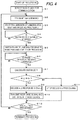
- Fig. 4 illustrates a flow of a series of processing carried out by the control unit 110 of the reader/writer 1 in order to achieve the processings as shown in Figs. 2 and 3 .
- step S1 processing for transmitting the query command and receiving and decoding the response from the tag 2 is carried out, and tags 2 ready for communication are detected.
- step S2 processing of step S2 and subsequent steps is executed.
- step S2 the Ack command is transmitted, and in step S3 subsequent thereto, transmission of the unmodulated wave and the decoding processing are started. Thereafter, in the decoding processing, the reader/writer 1 waits until decoding of the preamble of the response signal is started (step S4).
- step S4 When decoding of the preamble is started ("YES” in step S4), the phase of the unmodulated wave is switched from 0 degrees to 90 degrees, and the timer processing is started (step S5). Thereafter, while the phase of the reflected wave is detected using the I signal and the Q signal obtained with the timing at which the signal of "1" in the preamble is decoded, the reader/writer 1 waits until the phase changes substantially 90 degrees (step S6).
- the calculated distance R is compared with the reference distance R0.
- R ⁇ R0 holds ("YES” in step S8)
- the decoding processing is continuously performed, so that all the response signals are decoded (step S9). Further, the decoded response signal as well as the distance R are transmitted to the host device (step S10).
- R > R0 holds ("NO" in step S8)
- the processing proceeds to step S11 and the decoding processing is terminated.
- step S12 is determined to be "YES" upon finish of processing performed on all the tags, the processing is terminated.
- the switching of the phase of the unmodulated wave is cancelled after the decoding of the response signal is finished or terminated, and an Ack command for a subsequent tag is transmitted with a carrier wave having a phase of 0 degrees.
- Another command may be transmitted to the tags on which the processing of steps S9, S10 is executed, and responses therefrom may be received. In such a case, it is not necessary to carry out the processing for calculating the distance R again (steps S4 to S8).
- the measured time T does not include the delay time caused by the response time of the response transmitted by the tag 2 in reply to the command, and therefore, the distance R can be obtained by accurately calculating the time taken by the radio wave to go from antenna 10 to the tag 2 and from the tag 2 to the antenna 10.
- the reflected wave reflected by the tag 2 and directly returning back to the antenna 10 may reach the antenna 10.
- the former may reliably reach the antenna 10 earlier than the latter.
- the phase of the unmodulated wave is changed in response to the start of reception of the reflected wave transmitted from the tag 2, and the arrival of the direct wave in reply to the unmodulated wave immediately after the change of the phase can be easily detected by detecting the first change of the phase occurring in the reflected wave thereafter. Therefore, the distance R calculated according to the above embodiment is not affected by the reflected wave from the floors and the like, and the distance from the antenna 10 to the tag 2 can be accurately obtained.
- the distance R is measured while performing the processing for decoding the response signal transmitted from the tag 2, the distance can be measured within the cycle of normal communication processing, and information about the tag 2 can be obtained. Therefore, no problem would be caused in the communication with the moving tag 2.
- the decoding process is terminated for a response signal transmitted from a tag whose distance R is beyond the reference distance R0. Therefore, the processing can be performed efficiently, thereby preventing transmission of unnecessary information to the host device. Further, since not only the decoded response signal but also the calculation result of the distance R are transmitted to the host device, the host device can distinguish the information of the tag 2 and recognize the distance between the tag 2 and the antenna 10.
- the reader/writer 1 it is not necessary for the reader/writer 1 to select the response signal from the tag 2. That is, regardless of the value of the distance R, the response signals from all the tags 2 with which the reader/writer 1 communicates may be decoded, and each response signal as well as the distance R may be transmitted to the host device. Alternatively, only the processings up to the comparison processing between the distance R and the reference distance R0 may be performed, and information about the response signal from each tag associated with data showing the comparison result of the distance may be transmitted to the host device. In this manner, the host device can easily select the response signal.
- the phase of the unmodulated wave is changed by 90 degrees.
- the variation is not limited to 90 degrees, and may be set to another angle. Even in such a case, the distance R can be accurately obtained by measuring the time from when the phase of the unmodulated wave is switched to when change occurs in the reflected wave according to change of the phase in the unmodulated wave.
Description
- The present invention relates to a communication processing apparatus for communicating with an RFID tag using a continuous carrier wave, and more particularly relates to a technique for measuring a distance between a communication processing apparatus and an RFID tag (hereinafter, may be simply referred to as "tag") transmitting a response in reply to a command given by the communication processing apparatus.
- In a communication processing apparatus of an RFID method, the communication processing apparatus alternately performs processing for transmitting a command to a tag by modulating a carrier wave while continuously transmitting the carrier wave at a constant frequency and processing for receiving a response from the tag by transmitting an unmodulated carrier wave (Continuous Wave; abbreviated as CW). The tag having received the command responds to the command by changing the impedance of the circuit of the tag. As a result of response operation of this tag, a signal (reflected wave) carrying the response signal in reply to the command onto the unmodulated carrier wave is transmitted back to the communication processing apparatus, and then the response signal is decoded.
- In RFID systems used in sites such as production sites and logistics sites, it is necessary to communicate with a tag within the range of the communication distance defined in advance, but depending on the wavelength of the used radio wave, the radio wave may reach a location beyond the necessary distance. The radio wave may be reflected by floors and walls at the site, and may be guided to a tag far away. As a result, the tag residing at the location not requiring communication may respond to the command, and may cause a problem in information processing. A specific example is shown in
Fig. 5 . - In the example of
Fig. 5 , antennas A1, A2 of communication processing apparatuses are provided at a side of parallel paths B1, B2, respectively, and information is read out from a tag T attached to a vehicle C traveling along the paths B1, B2 using these antennas A1, A2. In the example shown in the figure, only the antenna A1 corresponding to the path B1 in which the vehicle C is located should be allowed to communicate with the tag T, but the radio waves transmitted from the antenna A2 in the adjacent path B2 also reach the tag T. As a result, the tag T responds to the command transmitted from the antenna A2, and incorrect information may be read and written. - As methods for solving the above issues, there may be considered a method for estimating a distance from an antenna to a tag based on a strength of a response signal from the tag and a method for measuring a distance to a tag using a time length from when a command is transmitted to when a response from the tag is received (e.g., see Japanese Patent No.
4462149 2008-232907 - There is also suggested a method for transmitting two kinds of carrier waves having different frequencies in order, detecting variation of a phase of a reflected wave transmitted from a tag for each frequency, and calculating a distance from the tag by performing calculation using a difference between the variations (see Patent Document 3).
-
- [Patent Document 1 ] Japanese Patent No.
4462149 - [Patent Document 2]
JP 2008-232907A - [Patent Document 3] Japanese Patent No.
4265686 - In the method for estimating a distance to a tag based on a strength of a response wave is useful when the strength of reflection of the tag is constant and the radio wave is less likely to be reflected by the floors and walls. In reality, however, the strength of reflection of the tag varies according to difference in the attachment state of the tag and the directional pattern. Unless special equipment such as an electromagnetic wave absorber is provided, it is difficult to prevent reflection of the radio waves on the floors and the walls.
- In the method for measuring a distance to a tag using a time length from when a command is transmitted to when a response from the tag is received, measuring accuracy cannot be ensured unless the response time at the tag in reply to the command (time from when the command arrives to when the response starts) is constant. In a tag of passive-type and semi-passive-type, the response time is not constant. Therefore, it is difficult to employ the above method.
- The method described in Patent Document 3 makes use of a principle of a phase difference occurring between the carrier wave transmitted to the tag and the reflected wave transmitted from the tag in accordance with the distance to the tag and the frequency of the carrier wave. In order to ensure the measuring accuracy with this method, it is necessary to increase the difference of frequencies of the two kinds of carrier waves as much as possible, but due to the limitation of the radio wave method, it is impossible to greatly change the frequencies. When not only a reflected wave directly returning back from the tag to the antenna (direct wave) but also reflected waves returning back from the tag to the antenna by way of reflection on the floors and the walls are received by the antenna, and a phase of a composite wave of these reflected waves is detected, the variation of the phase of the reflected waves does not correctly represent the distance to the tag.
- Therefore, it is difficult to put this method into practical use. Even if this method is put into practice, a plurality of times of communication processings are required, which makes it difficult to apply the method to a moving tag.
-
WO 02/088776 A2 - Moreover,
US 2010/0076722 A1 discloses a distance measuring apparatus comprising a transmitter, configured to transmit first one-frame signals from an antenna via radio waves having three or more different carrier frequencies, each of the first one-frame signals being composed of a request signal and a continuous carrier wave; a receiver, configured to receive second one-frame signals generated when the first one-frame signals are reflected by a reflector while being modulated, each of the second one-frame signals having a frequency corresponding to a frequency of an associated one of the first one-frame signals; a phase information acquirer, configured to calculate a phase change amount between the first one-frame signals and the second one-frame signals for each of the carrier frequencies; and a distance calculator, configured to calculate a distance between the antenna and the reflector by high-resolution spectrum analysis, on the basis of the carrier frequencies and the phase change amount calculated for each of the carrier frequencies. - In view of the above issues, an object of the present invention is to accurately measure the distance to the tag without deteriorating the efficiency of communication processing.
- In accordance with one aspect of the present invention, there is provided a communication processing apparatus having the features recited in
claim 1. - According to the above configuration, the phase of the continuous carrier wave is changed when the communication processing apparatus receives the reflected wave from the tag in a period in which the continuous carrier wave is transmitted in order to receive a response from the tag after the command is received. Then, a time is measured from when the phase is changed to when the same change of the phase is detected in the reflected wave received from the tag. The time taken for the radio wave to go from the communication processing apparatus to the tag and from the tag to the communication processing apparatus can be calculated from the measured time. Therefore, the distance to the tag can be measured accurately.
- In an embodiment of the above communication processing apparatus, the phase change unit changes the phase of the continuous carrier wave in response to detection of a preamble in the response information in the decoding processing. The preamble in the response signal is configured to have bit signals of "1" and "0" arranged in a certain pattern. Therefore, by detecting the pattern, start of reception of the reflected wave can be easily determined, and the phase can be switched. In addition, noise reflected wave reflected by floors and walls and returning back to the communication processing apparatus is prevented from being falsely recognized as a reflected wave from the tag.
- In another embodiment, the phase change unit changes the phase of the continuous carrier wave in response to detection of a preamble in the response signal in the decoding processing, and the phase detection unit detects change of the phase of the reflected wave transmitted in reply to the continuous carrier wave while the preamble is detected.
- According to this embodiment, the measuring processing of the distance can be finished while receiving the reflected wave including signals arranged in a certain pattern. Therefore, the distance can be reliably measured within one cycle of communication processing.
- A communication processing apparatus according to another embodiment further includes a determining unit for determining whether or not the RFID tag that returned the reflected wave is appropriate as a target of communication based on the distance measured by the distance measuring unit. In this manner, it is easy to employ only the response signals transmitted from the tags within the range of the defined distance, and this prevents false information processing from being carried out.
- A preferred mode of a communication processing apparatus according to the present invention is an RFID reader/writer for reading and writing information to/from the RFID tag. However, the preferred mode is not limited thereto, and it may be configured as an RFID reader for only reading information.
- In accordance with another aspect of the present invention, there is provided a distance measuring method having the features recited in claim 5.
- According to the present invention, the phase of the continuous carrier wave is changed in response to start of reception of the reflected wave from the RFID tag in reply to the command, and the distance to the tag is measured using a length of a time from when the continuous carrier wave is changed to when the same change of the phase occurs in the reflected wave. Therefore, the distance can be measured without being affected by variations of reflection strength and response time of the tag in reply to the command. When communication to a tag at a location beyond the necessary range is enabled due to radio waves reflected by the floors and the like, the measured time increases according to the reflection during the propagation, and accordingly, the measured value of the distance becomes a large value. This enables measurement that is less likely to be affected by the reflections from the floors and the like.
-
-
Fig. 1 is a block diagram illustrating a configuration of a reader/writer to which the present invention is applied; -
Fig. 2 is a time chart illustrating a flow of communication processing; -
Fig. 3 is a timing chart illustrating a relationship between changes of phases of an unmodulated carrier wave (CW) and a reflected wave and a time T measured based thereon; -
Fig. 4 is a flowchart illustrating a processing procedure in a control unit of the communication processing apparatus; and -
Fig. 5 is an explanatory diagram illustrating an example of incorrect communication processing. -
Fig. 1 is a block diagram illustrating a configuration of a reader/writer which is an example of a communication processing apparatus to which the present invention is applied. - A reader/
writer 1 according to this embodiment communicates with a passive-type or semi-passive-type RFID tag 2 using UHF band radio wave, reads information from thistag 2, and write information to thetag 2. The reader/writer 1 includes a transmission/reception circuit 100 including an antenna 10 and acontrol unit 110 for controlling operation of the transmission/reception circuit. It should be noted that the used radio wave is not limited to the UHF band. Radio waves in other bands may also be used. - The transmission/
reception circuit 100 includes not only an antenna 10 but also acirculator 11, anoscillator 12, amodulation circuit 13,distributors mixers degrees phase shifter 17,amplifiers 18A, 18B, A/D converters control unit 110 is actually a program logic circuit (FPGA), and is provided with functions of a transmission control unit 111, aphase detection unit 112, adistance calculation unit 113, adecoding processing unit 114, and anoutput processing unit 115. - Although not shown in
Fig. 1 , the reader/writer 1 is provided with an interface circuit for a host device (not shown). Thecontrol unit 110 carries out communication processing with a tag based on an instruction transmitted from a host device, and transmits a processing result to the host device. - The
oscillator 12 outputs a frequency signal serving as a basis of a carrier wave. Themodulation circuit 13 receives a data signal provided by the transmission control unit 111, and modulates a continuous carrier with the data signal. The modulated signal is guided to the antenna 10 via thecirculator 11, and transmitted as an electromagnetic wave. - The actual modulation occurs in a period in which a command is transmitted. In a period in which response is received from the
tag 2, an unmodulated carrier wave CW (hereinafter referred to as "unmodulated wave") is transmitted. - In addition, the
modulation circuit 13 includes a phase switching circuit for shifting the phase of the carrier wave. This circuit is activated in response to a phase switching command provided by the transmission control unit 111, and thereby the phase of the carrier wave is switched. In this embodiment, themodulation circuit 13 is constituted by an orthogonal modulation device, and the carrier wave phase is shifted by 90 degrees. However, the configuration of themodulation circuit 13 is not limited thereto. - The reflected wave received with the antenna 10 from the
tag 2 is guided via thecirculator 11 to thedistributor 15, and is distributed to each of themixers distributor 14 distributes the oscillation signal provided by theoscillator 12. One of the distributed signals is directly input to themixer 16A, and the other of the signals is input to themixer 16B via the 90degrees phase shifter 17. As a result, themixer 16A outputs an I signal included in the reflected wave, and themixer 16B outputs a Q signal included in the reflected wave. The I signal and the Q signal are respectively amplified by theamplifiers 18A, 18B, thereafter digitally converted by A/D conversion circuits control unit 110. - The I signal and the Q signal received by the
control unit 110 is processed by thephase detection unit 112 and thedecoding processing unit 114. - The
phase detection unit 112 uses the I signal and the Q signal to detect change of the phase of the reflected wave. For example, this detection processing is carried out by calculation processing for obtaining a strength ratio Q/I of the Q signal with respect to the I signal and processing for comparing each calculation result with a previous calculation result. - The
decoding processing unit 114 adopts the I signal and the Q signal as vectors on an IQ plane and obtains a length of a composite vector of these vectors. Then, based on time-series change of a length thereof, thedecoding processing unit 114 decodes a response signal from the tag included in the reflected wave. - After the transmission control unit 111 outputs the data signal constituting the command, the transmission control unit 111 transmits a continuous wave. Further, the transmission control unit 111 outputs a phase switching command to the
modulation circuit 13 in response to start of decoding of the response signal by thedecoding processing unit 114. With these processings, the electromagnetic wave transmitted from the antenna 10 changes from the carrier wave carrying the command to the unmodulated wave (CW), and further changes to an unmodulated wave whose phase is shifted by 90 degrees. - The
distance calculation unit 113 starts timer processing in response to output of the phase switching command, and measures the time until thephase detection unit 112 detects the same change in the phase of the reflected wave as that occurred in the unmodulated wave. Then, using the measured time, the distance from the antenna 10 to thetag 2 is calculated by executing calculation described below. - The
output processing unit 115 compares the distance calculated by thedistance calculation unit 113 with a reference distance transmitted from a host device in advance, and transmits, to the host device, a response signal transmitted from a tag whose distance is calculated as a distance within the reference distance. When the distance calculated by thedistance calculation unit 113 is determined to be more than the reference distance, thedecoding processing unit 114 determines that the communicating tag is not appropriate as a target of communication, and stops decoding processing. - Hereinafter, communication processing carried out by the reader/
writer 1 will be described in detail. Especially, a method for measuring the distance from the antenna 10 to thetag 2 will be mainly described. - First,
Fig. 2 illustrates, along a time axis, a flow of communication processing carried out between the reader/writer 1 and thetag 2. In this embodiment, based onEPCglobal C1 Gen 2 specification, the reader/writer 1 alternately carries out a period in which a carrier wave carrying a command is transmitted and a period in which a response from thetag 2 is received while transmitting an unmodulated wave (CW). The processing for measuring the distance to thetag 2 is also carried out during the period in which the unmodulated wave is transmitted. - Specific flow of the communication processing will be described with reference to
Fig. 2 . First, the reader/writer 1 transmits a detection command (query command) to all thetags 2 included in the communication range ((a) inFig. 2 ). Thetag 2 having received the command generates a random number, and transmits the random number to the reader/writer 1 ((b) inFig. 2 ). The reader/writer 1 having received the random number recognizes the number of tags within the communication range based on the number of receptions. Subsequently, the reader/writer 1 sequentially executes, for each tag, processing for identifying a tag with which the reader/writer communicates based on the received random number and transmitting a command (Ack command) for requesting reading of information, and processing for receiving a response signal from the tag in reply to the command ((c) (d) inFig. 2 ). While the response signal in reply to the Ack command is received, processing for switching the phase of the unmodulated wave and measuring processing of the distance are carried out ((e) inFig. 2 ). -
Fig. 3 schematically illustrates a relationship between the phase of the unmodulated wave and the phase of the reflected wave transmitted from thetag 2. Where the phase of the initially transmitted unmodulated wave (in synchronization with the frequency signal provided by the oscillator 12) is 0 degrees, the phase of the unmodulated wave is 90 degrees after the phase is switched. - The reflected wave transmitted from the
tag 2 in reply to the unmodulated wave transmitted from the antenna 10 returns back to the antenna 10 after a predetermined period of time has passed since the transmission. However, at this time, the phase of the reflected wave is shifted according to the distance from the antenna 10 to thetag 2 and the frequency of the unmodulated wave. In this case, this amount of shift is denoted as φ. - Since the frequency of the unmodulated wave is constant, the position of the
tag 2 is assumed to be almost the same. In this case, the amount of shift of the phase of the reflected wave is also φ even after the phase of the unmodulated wave is switched. Therefore, the phase difference between the reflected wave in reply to the unmodulated wave having the phase of 0 degrees and the reflected wave in reply to the unmodulated wave having the phase of 90 degrees is also almost 90 degrees. - In this embodiment, by making use of the above phenomenon, the phase of the unmodulated wave is switched from 0 degrees to 90 degrees in response to the start of reception of the reflected wave transmitted from the
tag 2. The start of reception of the reflected wave can be determined when thedecoding processing unit 114 detects a preamble at the head of the response signal. Therefore, in this embodiment, the phase of the unmodulated wave is switched in response to detection of several bits at the head of the preamble, and a time T is measured from when the phase is thus switched to when the phase of the reflected wave changes almost 90 degrees. - As described above, the timer processing is quickly started in response to the reflected wave reaching the reader/
writer 1 which is generated by the start of response to the command by thetag 2, and the timer processing is finished when the reflected wave transmitted by thetag 2 in reply to the switching portion of the phase of the unmodulated wave reaches the reader/writer 1. Therefore, it is possible to measure the time not including any delay time that is required by thetag 2 to receive the command and respond to the command. The measured time T is considered to include a delay time T0 caused by circuit characteristics of the reader/writer 1 and a time T1 for which the radio wave moves from the antenna to the tag and from the tag to the antenna. The delay time T0 is a fixed time that can be obtained from a propagation speed of the signal and a length of the signal line between thecontrol unit 110 and the antenna 10. - Therefore, in the
control unit 110 of this embodiment, the delay time T0 obtained in advance is registered, and thedistance calculation unit 113 derives a distance R from the antenna 10 to thetag 2 by executing the following arithmetic expression using the registered time T0 and the measured time T.
- In this embodiment, the phase of the unmodulated wave is immediately switched in response to the start of decoding of the preamble at the head portion of the response signal from the signal received by the antenna 10. Therefore, in most cases, the distance R can be calculated by detecting change of the phase of the reflected wave before decoding of the preamble is finished.
- In the preamble, signals "1" and "0" are arranged in a particular pattern. Therefore, start of reception of the reflected wave can be reliably detected. In addition, in the processing for detecting change of the phase, the accuracy of detection can be enhanced by using the phase detected from the I signal and the Q signal obtained with timing at which "1" is decoded.
- However, the timing of switching the phase of the unmodulated wave is not limited to the period in which the preamble is detected. The phase may be switched while a specific content of the response signal subsequent to the preamble is detected. The phase difference between the unmodulated wave not yet switched and the switched unmodulated wave is not limited to 90 degrees. As long as change of the phase of the reflected wave transmitted from the
tag 2 can be detected using the I signal and the Q signal, the phase difference may be any angle. -
Fig. 4 illustrates a flow of a series of processing carried out by thecontrol unit 110 of the reader/writer 1 in order to achieve the processings as shown inFigs. 2 and 3 . - First, in step S1, processing for transmitting the query command and receiving and decoding the response from the
tag 2 is carried out, and tags 2 ready for communication are detected. - Thereafter, for each of the detected
tags 2, processing of step S2 and subsequent steps is executed. - First, in step S2, the Ack command is transmitted, and in step S3 subsequent thereto, transmission of the unmodulated wave and the decoding processing are started. Thereafter, in the decoding processing, the reader/
writer 1 waits until decoding of the preamble of the response signal is started (step S4). - When decoding of the preamble is started ("YES" in step S4), the phase of the unmodulated wave is switched from 0 degrees to 90 degrees, and the timer processing is started (step S5). Thereafter, while the phase of the reflected wave is detected using the I signal and the Q signal obtained with the timing at which the signal of "1" in the preamble is decoded, the reader/
writer 1 waits until the phase changes substantially 90 degrees (step S6). - When determined that the above change has occurred ("YES" in step S6), the above arithmetic expression [R = c • (T - T0)/2] is executed using the measured time T up to the time when the change has occurred, thereby calculating the distance R from the antenna 10 to the tag 2 (step S7).
- Subsequently, the calculated distance R is compared with the reference distance R0. When R ≤ R0 holds ("YES" in step S8), the decoding processing is continuously performed, so that all the response signals are decoded (step S9). Further, the decoded response signal as well as the distance R are transmitted to the host device (step S10). On the other hand, when R > R0 holds ("NO" in step S8), the processing proceeds to step S11 and the decoding processing is terminated.
- By carrying out the same processing, only the response signals from the tags whose distances R are within the reference distance R0 are decoded, and the response signals as well as the distances R are transmitted to the host device. When step S12 is determined to be "YES" upon finish of processing performed on all the tags, the processing is terminated. The switching of the phase of the unmodulated wave is cancelled after the decoding of the response signal is finished or terminated, and an Ack command for a subsequent tag is transmitted with a carrier wave having a phase of 0 degrees. Another command may be transmitted to the tags on which the processing of steps S9, S10 is executed, and responses therefrom may be received. In such a case, it is not necessary to carry out the processing for calculating the distance R again (steps S4 to S8).
- As described above, the measured time T according to this embodiment does not include the delay time caused by the response time of the response transmitted by the
tag 2 in reply to the command, and therefore, the distance R can be obtained by accurately calculating the time taken by the radio wave to go from antenna 10 to thetag 2 and from thetag 2 to the antenna 10. Not only the reflected wave reflected by thetag 2 and directly returning back to the antenna 10 (direct wave) but also reflected waves returning back from thetag 2 to the antenna 10 by way of reflection on the floors and the like may reach the antenna 10. However, the former may reliably reach the antenna 10 earlier than the latter. Therefore, the phase of the unmodulated wave is changed in response to the start of reception of the reflected wave transmitted from thetag 2, and the arrival of the direct wave in reply to the unmodulated wave immediately after the change of the phase can be easily detected by detecting the first change of the phase occurring in the reflected wave thereafter. Therefore, the distance R calculated according to the above embodiment is not affected by the reflected wave from the floors and the like, and the distance from the antenna 10 to thetag 2 can be accurately obtained. - Since the distance R is measured while performing the processing for decoding the response signal transmitted from the
tag 2, the distance can be measured within the cycle of normal communication processing, and information about thetag 2 can be obtained. Therefore, no problem would be caused in the communication with the movingtag 2. On the other hand, the decoding process is terminated for a response signal transmitted from a tag whose distance R is beyond the reference distance R0. Therefore, the processing can be performed efficiently, thereby preventing transmission of unnecessary information to the host device. Further, since not only the decoded response signal but also the calculation result of the distance R are transmitted to the host device, the host device can distinguish the information of thetag 2 and recognize the distance between thetag 2 and the antenna 10. - However, it is not necessary for the reader/
writer 1 to select the response signal from thetag 2. That is, regardless of the value of the distance R, the response signals from all thetags 2 with which the reader/writer 1 communicates may be decoded, and each response signal as well as the distance R may be transmitted to the host device. Alternatively, only the processings up to the comparison processing between the distance R and the reference distance R0 may be performed, and information about the response signal from each tag associated with data showing the comparison result of the distance may be transmitted to the host device. In this manner, the host device can easily select the response signal. - In the above embodiment, the phase of the unmodulated wave is changed by 90 degrees. However, the variation is not limited to 90 degrees, and may be set to another angle. Even in such a case, the distance R can be accurately obtained by measuring the time from when the phase of the unmodulated wave is switched to when change occurs in the reflected wave according to change of the phase in the unmodulated wave.
-
- 1
- communication processing apparatus (reader/writer)
- 2
- RFID tag
- 100
- transmission/reception circuit
- 111
- transmission control unit
- 112
- phase detection unit
- 113
- distance calculation unit
- 114
- decoding processing unit
Claims (5)
- A communication processing apparatus (1) which executes command transmission processing for transmitting a command to an RFID tag (2) by modulating a carrier wave, reception processing, in which the communication processing apparatus (1) transmits a continuous carrier wave while receiving a reflected wave from the RFID tag (2) in reply to the continuous carrier wave, and decoding processing for decoding a response signal given by the RFID tag (2) from the received reflected wave, the apparatus being characterized by comprising:a phase detection unit (112) for detecting a phase of the reflected wave received in the reception processing;a phase change unit (16B) for changing a phase of the continuous carrier wave in response to start of reception of the reflected wave in the reception processing; anda distance measuring unit (113) for measuring a time from when the phase of the continuous carrier wave is changed to when change occurs in the phase of the reflected wave detected by the phase detection unit (112) according to the change of the phase in the continuous carrier wave, and using the measured time to measure a distance to the RFID tag (2) that returned the reflected wave.
- The communication processing apparatus (1) according to claim 1, wherein the phase change unit changes the phase of the continuous carrier wave in response to detection of a preamble in the response signal in the decoding processing.
- The communication processing apparatus (1) according to claim 1, wherein the phase change unit changes the phase of the continuous carrier wave in response to detection of a preamble in the response signal in the decoding processing, and
the phase detection unit (112) detects change of the phase of the reflected wave transmitted while the preamble is detected. - The communication processing apparatus (1) according to claim 1 further comprising:a determining unit for determining whether or not the RFID tag (2) that returned the reflected wave is appropriate as a target of communication based on the distance measured by the distance measuring unit (113).
- A distance measuring method performed by a communication processing apparatus (1) that executes a command transmission processing for transmitting a command to an RFID tag (2) by modulating a carrier wave, a reception processing, in which the communication processing apparatus (1) transmits a continuous carrier wave while receiving a reflected wave from the RFID tag (2) in reply to the continuous carrier wave, and a decoding processing for decoding a response signal given by the RFID tag (2) included in the received reflected wave, the method being characterized by comprising the steps of:changing a phase of the continuous carrier wave in response to start of reception of the reflected wave in the reception processing; andthereafter, while detecting a phase of the reflected wave, measuring a time until change occurs in the phase of the reflected wave according to the change of the phase in the continuous carrier wave, and using the measured time to measure a distance to the RFID tag (2) that returned the reflected wave.
Applications Claiming Priority (1)
| Application Number | Priority Date | Filing Date | Title |
|---|---|---|---|
| JP2011047497A JP5712680B2 (en) | 2011-03-04 | 2011-03-04 | Communication processing device and distance measurement method in communication processing device |
Publications (2)
| Publication Number | Publication Date |
|---|---|
| EP2495584A1 EP2495584A1 (en) | 2012-09-05 |
| EP2495584B1 true EP2495584B1 (en) | 2016-07-20 |
Family
ID=45554428
Family Applications (1)
| Application Number | Title | Priority Date | Filing Date |
|---|---|---|---|
| EP11188980.4A Active EP2495584B1 (en) | 2011-03-04 | 2011-11-14 | Communication processing apparatus and distance measuring method for communication processing apparatus |
Country Status (4)
| Country | Link |
|---|---|
| US (1) | US8717227B2 (en) |
| EP (1) | EP2495584B1 (en) |
| JP (1) | JP5712680B2 (en) |
| CN (1) | CN102655436B (en) |
Families Citing this family (11)
| Publication number | Priority date | Publication date | Assignee | Title |
|---|---|---|---|---|
| CN103366213B (en) * | 2012-03-31 | 2016-08-03 | 华矽半导体股份有限公司 | Active electric subtab and method for modulating signal thereof |
| US9721130B2 (en) | 2012-09-14 | 2017-08-01 | Nec Corporation | Article management system |
| CN102998654A (en) * | 2012-11-23 | 2013-03-27 | 无锡儒安科技有限公司 | Method and device of label phase information and based on passive wireless radio frequency recognition |
| CN105900348B (en) * | 2014-01-13 | 2018-12-14 | 克莱尔瓦扬技术有限公司 | Use the RF system of the PR-ASK with quadrature shift |
| CN106557982A (en) * | 2015-09-22 | 2017-04-05 | 中国联合网络通信集团有限公司 | A kind of laboratory equlpment management method and management system |
| US9551780B1 (en) * | 2016-01-02 | 2017-01-24 | International Business Machines Corporation | Locating an object based on charging/response time |
| EP3373192B1 (en) * | 2017-03-07 | 2019-09-18 | Denso Wave Incorporated | Tag reader |
| JP6881198B2 (en) * | 2017-09-29 | 2021-06-02 | 株式会社デンソーウェーブ | Wireless tag movement detection device |
| CN110082746B (en) * | 2018-01-25 | 2023-06-09 | 株式会社东芝 | Distance measuring device and distance measuring method |
| JP7159132B2 (en) * | 2019-09-05 | 2022-10-24 | 株式会社東芝 | rangefinder |
| CN112649784B (en) * | 2020-12-07 | 2023-07-04 | 西华大学 | Passive radio frequency tag ranging technology based on tag equivalent impedance model |
Family Cites Families (14)
| Publication number | Priority date | Publication date | Assignee | Title |
|---|---|---|---|---|
| JPH04265686A (en) | 1991-02-21 | 1992-09-21 | Fuji Electric Co Ltd | Sine wave driving method for ac synchronous servo motor |
| US20030013146A1 (en) * | 2001-05-02 | 2003-01-16 | Jay Werb | Hybrid real time locating system and methodology |
| WO2006095828A1 (en) * | 2005-03-09 | 2006-09-14 | Omron Corporation | Distance measuring apparatus, distance measuring method and communication system |
| WO2006095463A1 (en) | 2005-03-09 | 2006-09-14 | Omron Corporation | Distance measuring apparatus, distance measuring method, reflector and communication system |
| JP2008021188A (en) * | 2006-07-13 | 2008-01-31 | Matsushita Electric Ind Co Ltd | Transmitting/receiving system and transmitting/receiving method |
| JP4462149B2 (en) | 2005-09-07 | 2010-05-12 | 株式会社日立製作所 | Wireless tag search method and apparatus |
| US7561048B2 (en) * | 2005-12-15 | 2009-07-14 | Invisitrack, Inc. | Methods and system for reduced attenuation in tracking objects using RF technology |
| JP4270299B2 (en) * | 2006-03-28 | 2009-05-27 | オムロン株式会社 | RFID tag distance measuring device and RFID tag distance measuring system |
| JP2008199411A (en) * | 2007-02-14 | 2008-08-28 | Omron Corp | Frequency switcher, rfid system and distance measuring apparatus incorporating the frequency switcher |
| JP2008232907A (en) | 2007-03-22 | 2008-10-02 | Kyushu Ten:Kk | Ranging system and its ranging method |
| JP2009002886A (en) * | 2007-06-25 | 2009-01-08 | Brother Ind Ltd | Distance measuring system and positioning system |
| JP5355936B2 (en) | 2007-06-28 | 2013-11-27 | 日本信号株式会社 | Reader / writer and article sorting system |
| JP5173623B2 (en) * | 2008-06-19 | 2013-04-03 | パナソニック株式会社 | Wireless ranging system and wireless ranging method |
| JP2012088125A (en) * | 2010-10-18 | 2012-05-10 | Denso Wave Inc | Wireless tag distance calculation system and wireless tag reader |
-
2011
- 2011-03-04 JP JP2011047497A patent/JP5712680B2/en active Active
- 2011-11-14 EP EP11188980.4A patent/EP2495584B1/en active Active
- 2011-11-15 CN CN201110369576.1A patent/CN102655436B/en active Active
- 2011-11-16 US US13/297,726 patent/US8717227B2/en active Active
Also Published As
| Publication number | Publication date |
|---|---|
| JP2012184997A (en) | 2012-09-27 |
| EP2495584A1 (en) | 2012-09-05 |
| JP5712680B2 (en) | 2015-05-07 |
| US20120223854A1 (en) | 2012-09-06 |
| CN102655436A (en) | 2012-09-05 |
| CN102655436B (en) | 2015-05-13 |
| US8717227B2 (en) | 2014-05-06 |
Similar Documents
| Publication | Publication Date | Title |
|---|---|---|
| EP2495584B1 (en) | Communication processing apparatus and distance measuring method for communication processing apparatus | |
| US11403473B2 (en) | Systems and methods to determine kinematical parameters | |
| EP2169593B1 (en) | Reader/writer, and article sorting system | |
| JP4239033B2 (en) | Interrogator for RFID tag communication system | |
| US20160102964A1 (en) | Methods and Systems for Estimating Distance of a Radio Frequency Identification Tag | |
| CN105022058A (en) | Method and system for determining the distance, speed, and/or direction of movement of an rfid transponder | |
| EP1738195A1 (en) | Contactless reader/writer | |
| US9983303B2 (en) | Passive radio frequency identification ranging | |
| JP4265554B2 (en) | Tag communication device, tag communication method, and tag communication system | |
| US20130181858A1 (en) | Radar system, transponder device, method for radar processing and computer readable media | |
| JP5514707B2 (en) | Wireless communication apparatus and wireless communication method | |
| EP2300849B1 (en) | A system for reading information transmitted from a transponder | |
| JP5611511B2 (en) | Reader / writer and article sorting system | |
| US8436765B2 (en) | Communication processing device and distance measurement method in communication processing device | |
| JP2005345198A (en) | Interrogator for wireless tag communication system and wireless tag communication system | |
| EP2523018A1 (en) | Communication processing device, and method for measuring distances in communication processing device | |
| US10958360B2 (en) | Transceiver and method for distance measurement | |
| US11506777B2 (en) | RFID tag location and association of RFID tags | |
| JP5474330B2 (en) | Reader / writer system |
Legal Events
| Date | Code | Title | Description |
|---|---|---|---|
| PUAI | Public reference made under article 153(3) epc to a published international application that has entered the european phase |
Free format text: ORIGINAL CODE: 0009012 |
|
| AK | Designated contracting states |
Kind code of ref document: A1 Designated state(s): AL AT BE BG CH CY CZ DE DK EE ES FI FR GB GR HR HU IE IS IT LI LT LU LV MC MK MT NL NO PL PT RO RS SE SI SK SM TR |
|
| AX | Request for extension of the european patent |
Extension state: BA ME |
|
| 17P | Request for examination filed |
Effective date: 20120817 |
|
| 17Q | First examination report despatched |
Effective date: 20140509 |
|
| GRAP | Despatch of communication of intention to grant a patent |
Free format text: ORIGINAL CODE: EPIDOSNIGR1 |
|
| INTG | Intention to grant announced |
Effective date: 20160216 |
|
| RIN1 | Information on inventor provided before grant (corrected) |
Inventor name: MATSUI, SHUICHI Inventor name: KASAI, HOROKAZU Inventor name: NOGAMI, HIDEKATSU |
|
| GRAS | Grant fee paid |
Free format text: ORIGINAL CODE: EPIDOSNIGR3 |
|
| GRAA | (expected) grant |
Free format text: ORIGINAL CODE: 0009210 |
|
| AK | Designated contracting states |
Kind code of ref document: B1 Designated state(s): AL AT BE BG CH CY CZ DE DK EE ES FI FR GB GR HR HU IE IS IT LI LT LU LV MC MK MT NL NO PL PT RO RS SE SI SK SM TR |
|
| REG | Reference to a national code |
Ref country code: GB Ref legal event code: FG4D |
|
| REG | Reference to a national code |
Ref country code: CH Ref legal event code: EP |
|
| REG | Reference to a national code |
Ref country code: IE Ref legal event code: FG4D |
|
| REG | Reference to a national code |
Ref country code: AT Ref legal event code: REF Ref document number: 814518 Country of ref document: AT Kind code of ref document: T Effective date: 20160815 |
|
| REG | Reference to a national code |
Ref country code: DE Ref legal event code: R096 Ref document number: 602011028290 Country of ref document: DE |
|
| REG | Reference to a national code |
Ref country code: LT Ref legal event code: MG4D |
|
| REG | Reference to a national code |
Ref country code: NL Ref legal event code: MP Effective date: 20160720 |
|
| REG | Reference to a national code |
Ref country code: AT Ref legal event code: MK05 Ref document number: 814518 Country of ref document: AT Kind code of ref document: T Effective date: 20160720 |
|
| PG25 | Lapsed in a contracting state [announced via postgrant information from national office to epo] |
Ref country code: LT Free format text: LAPSE BECAUSE OF FAILURE TO SUBMIT A TRANSLATION OF THE DESCRIPTION OR TO PAY THE FEE WITHIN THE PRESCRIBED TIME-LIMIT Effective date: 20160720 Ref country code: NL Free format text: LAPSE BECAUSE OF FAILURE TO SUBMIT A TRANSLATION OF THE DESCRIPTION OR TO PAY THE FEE WITHIN THE PRESCRIBED TIME-LIMIT Effective date: 20160720 Ref country code: HR Free format text: LAPSE BECAUSE OF FAILURE TO SUBMIT A TRANSLATION OF THE DESCRIPTION OR TO PAY THE FEE WITHIN THE PRESCRIBED TIME-LIMIT Effective date: 20160720 Ref country code: NO Free format text: LAPSE BECAUSE OF FAILURE TO SUBMIT A TRANSLATION OF THE DESCRIPTION OR TO PAY THE FEE WITHIN THE PRESCRIBED TIME-LIMIT Effective date: 20161020 Ref country code: RS Free format text: LAPSE BECAUSE OF FAILURE TO SUBMIT A TRANSLATION OF THE DESCRIPTION OR TO PAY THE FEE WITHIN THE PRESCRIBED TIME-LIMIT Effective date: 20160720 Ref country code: IT Free format text: LAPSE BECAUSE OF FAILURE TO SUBMIT A TRANSLATION OF THE DESCRIPTION OR TO PAY THE FEE WITHIN THE PRESCRIBED TIME-LIMIT Effective date: 20160720 Ref country code: IS Free format text: LAPSE BECAUSE OF FAILURE TO SUBMIT A TRANSLATION OF THE DESCRIPTION OR TO PAY THE FEE WITHIN THE PRESCRIBED TIME-LIMIT Effective date: 20161120 Ref country code: FI Free format text: LAPSE BECAUSE OF FAILURE TO SUBMIT A TRANSLATION OF THE DESCRIPTION OR TO PAY THE FEE WITHIN THE PRESCRIBED TIME-LIMIT Effective date: 20160720 |
|
| PG25 | Lapsed in a contracting state [announced via postgrant information from national office to epo] |
Ref country code: BE Free format text: LAPSE BECAUSE OF NON-PAYMENT OF DUE FEES Effective date: 20160720 Ref country code: PT Free format text: LAPSE BECAUSE OF FAILURE TO SUBMIT A TRANSLATION OF THE DESCRIPTION OR TO PAY THE FEE WITHIN THE PRESCRIBED TIME-LIMIT Effective date: 20161121 Ref country code: LV Free format text: LAPSE BECAUSE OF FAILURE TO SUBMIT A TRANSLATION OF THE DESCRIPTION OR TO PAY THE FEE WITHIN THE PRESCRIBED TIME-LIMIT Effective date: 20160720 Ref country code: ES Free format text: LAPSE BECAUSE OF FAILURE TO SUBMIT A TRANSLATION OF THE DESCRIPTION OR TO PAY THE FEE WITHIN THE PRESCRIBED TIME-LIMIT Effective date: 20160720 Ref country code: GR Free format text: LAPSE BECAUSE OF FAILURE TO SUBMIT A TRANSLATION OF THE DESCRIPTION OR TO PAY THE FEE WITHIN THE PRESCRIBED TIME-LIMIT Effective date: 20161021 Ref country code: SE Free format text: LAPSE BECAUSE OF FAILURE TO SUBMIT A TRANSLATION OF THE DESCRIPTION OR TO PAY THE FEE WITHIN THE PRESCRIBED TIME-LIMIT Effective date: 20160720 Ref country code: AT Free format text: LAPSE BECAUSE OF FAILURE TO SUBMIT A TRANSLATION OF THE DESCRIPTION OR TO PAY THE FEE WITHIN THE PRESCRIBED TIME-LIMIT Effective date: 20160720 Ref country code: PL Free format text: LAPSE BECAUSE OF FAILURE TO SUBMIT A TRANSLATION OF THE DESCRIPTION OR TO PAY THE FEE WITHIN THE PRESCRIBED TIME-LIMIT Effective date: 20160720 |
|
| REG | Reference to a national code |
Ref country code: DE Ref legal event code: R097 Ref document number: 602011028290 Country of ref document: DE |
|
| PG25 | Lapsed in a contracting state [announced via postgrant information from national office to epo] |
Ref country code: RO Free format text: LAPSE BECAUSE OF FAILURE TO SUBMIT A TRANSLATION OF THE DESCRIPTION OR TO PAY THE FEE WITHIN THE PRESCRIBED TIME-LIMIT Effective date: 20160720 Ref country code: EE Free format text: LAPSE BECAUSE OF FAILURE TO SUBMIT A TRANSLATION OF THE DESCRIPTION OR TO PAY THE FEE WITHIN THE PRESCRIBED TIME-LIMIT Effective date: 20160720 |
|
| PLBE | No opposition filed within time limit |
Free format text: ORIGINAL CODE: 0009261 |
|
| STAA | Information on the status of an ep patent application or granted ep patent |
Free format text: STATUS: NO OPPOSITION FILED WITHIN TIME LIMIT |
|
| PG25 | Lapsed in a contracting state [announced via postgrant information from national office to epo] |
Ref country code: SK Free format text: LAPSE BECAUSE OF FAILURE TO SUBMIT A TRANSLATION OF THE DESCRIPTION OR TO PAY THE FEE WITHIN THE PRESCRIBED TIME-LIMIT Effective date: 20160720 Ref country code: CZ Free format text: LAPSE BECAUSE OF FAILURE TO SUBMIT A TRANSLATION OF THE DESCRIPTION OR TO PAY THE FEE WITHIN THE PRESCRIBED TIME-LIMIT Effective date: 20160720 Ref country code: BG Free format text: LAPSE BECAUSE OF FAILURE TO SUBMIT A TRANSLATION OF THE DESCRIPTION OR TO PAY THE FEE WITHIN THE PRESCRIBED TIME-LIMIT Effective date: 20161020 Ref country code: SM Free format text: LAPSE BECAUSE OF FAILURE TO SUBMIT A TRANSLATION OF THE DESCRIPTION OR TO PAY THE FEE WITHIN THE PRESCRIBED TIME-LIMIT Effective date: 20160720 Ref country code: DK Free format text: LAPSE BECAUSE OF FAILURE TO SUBMIT A TRANSLATION OF THE DESCRIPTION OR TO PAY THE FEE WITHIN THE PRESCRIBED TIME-LIMIT Effective date: 20160720 |
|
| 26N | No opposition filed |
Effective date: 20170421 |
|
| REG | Reference to a national code |
Ref country code: CH Ref legal event code: PL |
|
| GBPC | Gb: european patent ceased through non-payment of renewal fee |
Effective date: 20161114 |
|
| PG25 | Lapsed in a contracting state [announced via postgrant information from national office to epo] |
Ref country code: CH Free format text: LAPSE BECAUSE OF NON-PAYMENT OF DUE FEES Effective date: 20161130 Ref country code: LI Free format text: LAPSE BECAUSE OF NON-PAYMENT OF DUE FEES Effective date: 20161130 |
|
| REG | Reference to a national code |
Ref country code: IE Ref legal event code: MM4A |
|
| REG | Reference to a national code |
Ref country code: FR Ref legal event code: ST Effective date: 20170731 |
|
| PG25 | Lapsed in a contracting state [announced via postgrant information from national office to epo] |
Ref country code: SI Free format text: LAPSE BECAUSE OF FAILURE TO SUBMIT A TRANSLATION OF THE DESCRIPTION OR TO PAY THE FEE WITHIN THE PRESCRIBED TIME-LIMIT Effective date: 20160720 |
|
| PG25 | Lapsed in a contracting state [announced via postgrant information from national office to epo] |
Ref country code: LU Free format text: LAPSE BECAUSE OF NON-PAYMENT OF DUE FEES Effective date: 20161130 |
|
| PG25 | Lapsed in a contracting state [announced via postgrant information from national office to epo] |
Ref country code: FR Free format text: LAPSE BECAUSE OF NON-PAYMENT OF DUE FEES Effective date: 20161130 |
|
| PG25 | Lapsed in a contracting state [announced via postgrant information from national office to epo] |
Ref country code: GB Free format text: LAPSE BECAUSE OF NON-PAYMENT OF DUE FEES Effective date: 20161114 Ref country code: IE Free format text: LAPSE BECAUSE OF NON-PAYMENT OF DUE FEES Effective date: 20161114 |
|
| PG25 | Lapsed in a contracting state [announced via postgrant information from national office to epo] |
Ref country code: HU Free format text: LAPSE BECAUSE OF FAILURE TO SUBMIT A TRANSLATION OF THE DESCRIPTION OR TO PAY THE FEE WITHIN THE PRESCRIBED TIME-LIMIT; INVALID AB INITIO Effective date: 20111114 Ref country code: CY Free format text: LAPSE BECAUSE OF FAILURE TO SUBMIT A TRANSLATION OF THE DESCRIPTION OR TO PAY THE FEE WITHIN THE PRESCRIBED TIME-LIMIT Effective date: 20160720 |
|
| PG25 | Lapsed in a contracting state [announced via postgrant information from national office to epo] |
Ref country code: MK Free format text: LAPSE BECAUSE OF FAILURE TO SUBMIT A TRANSLATION OF THE DESCRIPTION OR TO PAY THE FEE WITHIN THE PRESCRIBED TIME-LIMIT Effective date: 20160720 Ref country code: MC Free format text: LAPSE BECAUSE OF FAILURE TO SUBMIT A TRANSLATION OF THE DESCRIPTION OR TO PAY THE FEE WITHIN THE PRESCRIBED TIME-LIMIT Effective date: 20160720 Ref country code: TR Free format text: LAPSE BECAUSE OF FAILURE TO SUBMIT A TRANSLATION OF THE DESCRIPTION OR TO PAY THE FEE WITHIN THE PRESCRIBED TIME-LIMIT Effective date: 20160720 |
|
| PG25 | Lapsed in a contracting state [announced via postgrant information from national office to epo] |
Ref country code: MT Free format text: LAPSE BECAUSE OF NON-PAYMENT OF DUE FEES Effective date: 20161114 |
|
| PG25 | Lapsed in a contracting state [announced via postgrant information from national office to epo] |
Ref country code: AL Free format text: LAPSE BECAUSE OF FAILURE TO SUBMIT A TRANSLATION OF THE DESCRIPTION OR TO PAY THE FEE WITHIN THE PRESCRIBED TIME-LIMIT Effective date: 20160720 |
|
| PGFP | Annual fee paid to national office [announced via postgrant information from national office to epo] |
Ref country code: DE Payment date: 20230929 Year of fee payment: 13 |