EP2495553A2 - Tragbares Boroskop zur Untersuchung von Turbomaschinenschaufeln - Google Patents
Tragbares Boroskop zur Untersuchung von Turbomaschinenschaufeln Download PDFInfo
- Publication number
- EP2495553A2 EP2495553A2 EP12157774A EP12157774A EP2495553A2 EP 2495553 A2 EP2495553 A2 EP 2495553A2 EP 12157774 A EP12157774 A EP 12157774A EP 12157774 A EP12157774 A EP 12157774A EP 2495553 A2 EP2495553 A2 EP 2495553A2
- Authority
- EP
- European Patent Office
- Prior art keywords
- boroscope
- battery
- portable
- protective case
- probe
- Prior art date
- Legal status (The legal status is an assumption and is not a legal conclusion. Google has not performed a legal analysis and makes no representation as to the accuracy of the status listed.)
- Ceased
Links
Images


Classifications
-
- G—PHYSICS
- G01—MEASURING; TESTING
- G01N—INVESTIGATING OR ANALYSING MATERIALS BY DETERMINING THEIR CHEMICAL OR PHYSICAL PROPERTIES
- G01N21/00—Investigating or analysing materials by the use of optical means, i.e. using sub-millimetre waves, infrared, visible or ultraviolet light
- G01N21/84—Systems specially adapted for particular applications
- G01N21/88—Investigating the presence of flaws or contamination
- G01N21/95—Investigating the presence of flaws or contamination characterised by the material or shape of the object to be examined
- G01N21/954—Inspecting the inner surface of hollow bodies, e.g. bores
-
- F—MECHANICAL ENGINEERING; LIGHTING; HEATING; WEAPONS; BLASTING
- F01—MACHINES OR ENGINES IN GENERAL; ENGINE PLANTS IN GENERAL; STEAM ENGINES
- F01D—NON-POSITIVE DISPLACEMENT MACHINES OR ENGINES, e.g. STEAM TURBINES
- F01D21/00—Shutting-down of machines or engines, e.g. in emergency; Regulating, controlling, or safety means not otherwise provided for
- F01D21/003—Arrangements for testing or measuring
-
- F—MECHANICAL ENGINEERING; LIGHTING; HEATING; WEAPONS; BLASTING
- F01—MACHINES OR ENGINES IN GENERAL; ENGINE PLANTS IN GENERAL; STEAM ENGINES
- F01D—NON-POSITIVE DISPLACEMENT MACHINES OR ENGINES, e.g. STEAM TURBINES
- F01D5/00—Blades; Blade-carrying members; Heating, heat-insulating, cooling or antivibration means on the blades or the members
- F01D5/005—Repairing methods or devices
-
- G—PHYSICS
- G02—OPTICS
- G02B—OPTICAL ELEMENTS, SYSTEMS OR APPARATUS
- G02B23/00—Telescopes, e.g. binoculars; Periscopes; Instruments for viewing the inside of hollow bodies; Viewfinders; Optical aiming or sighting devices
- G02B23/24—Instruments or systems for viewing the inside of hollow bodies, e.g. fibrescopes
- G02B23/2476—Non-optical details, e.g. housings, mountings, supports
- G02B23/2492—Arrangements for use in a hostile environment, e.g. a very hot, cold or radioactive environment
-
- F—MECHANICAL ENGINEERING; LIGHTING; HEATING; WEAPONS; BLASTING
- F05—INDEXING SCHEMES RELATING TO ENGINES OR PUMPS IN VARIOUS SUBCLASSES OF CLASSES F01-F04
- F05D—INDEXING SCHEME FOR ASPECTS RELATING TO NON-POSITIVE-DISPLACEMENT MACHINES OR ENGINES, GAS-TURBINES OR JET-PROPULSION PLANTS
- F05D2230/00—Manufacture
- F05D2230/80—Repairing, retrofitting or upgrading methods
Definitions
- This disclosure relates generally to inspecting turbomachine components and, more particularly, to inspecting turbomachine blades using a portable boroscope.
- Turbomachines include various blades. Some blades rotate during operation. Other blades remain stationary. The blades may operate in high temperatures environments. Exposure to sufficiently high temperatures can damage the blades as is known. Accordingly, many blades include internal passages that communicate a flow of air through the blades. The flow of air removes thermal energy from the blades to cool the blades.
- Blades become worn over time, and some blades may become damaged. Operating the turbomachine with worn or damaged blades can reduce the efficiency of the turbomachine. Replacement blades are expensive to manufacture. Thus, it is often desirable to refurbish worn or damaged blades, rather than replacing worm or damaged blades with new blades.
- the internal passages in the blades are periodically inspected during a refurbishing procedure.
- the inspection identifies blockages, internal damage, etc.
- the internal passages of newly manufactured blades typically undergo a similar inspection.
- Technicians may use bench-based boroscopes to inspect the internal passages. Inspecting the blades using bench-based boroscopes is time consuming as the blades must be moved to the location of the bench-based boroscope.
- An example portable boroscope assembly for inspecting passages within a turbomachine blade includes a boroscope probe and a display screen.
- the display screen is configured to show images of areas inspected by the boroscope probe.
- a battery powers the display screen.
- a protective case holds at least the display screen and the battery. The protective case defines an aperture. The display screen is viewable through the aperture.
- Another example portable boroscope assembly for inspecting passages within a turbomachine blade includes a camera and a probe tip operatively coupled with the camera.
- the assembly also includes a display and a light that are operatively coupled to the probe tip.
- a battery powers the camera, the display, and the light.
- the protective case holds at least the display and the battery.
- An example method of inspecting a turbomachine blade using a boroscope inspection assembly includes powering a boroscope inspection device using a battery and inspecting a fluid passage established within a turbomachine blade using the boroscope inspection device.
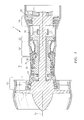
- an example turbomachine such as a gas turbine engine 10 is circumferentially disposed about an axis 12.
- the gas turbine engine 10 includes a fan 14, a low pressure compressor section 16, a high pressure compressor section 18, a combustion section 20, a high pressure turbine section 22, and a low pressure turbine section 24.
- Other example turbomachines may include more or fewer sections.
- the high pressure compressor section 18 includes a rotor 32.
- the low pressure compressor section 16 includes a rotor 33.
- the rotors 32 and 33 are configured to rotate about the axis 12.
- the example rotors 32 and 33 include alternating rows of rotating airfoils or rotating blades 34 and static airfoils or static blades 36.
- the static blades 36 may also be referred to as static vanes.
- the high pressure turbine section 22 includes a rotor 26.
- the low pressure turbine section 24 includes a rotor 27.
- the rotors 26 and 27 are configured to rotate about the axis 12 in response to expansion to drive the high pressure compressor section 18 and the low pressure compressor section 16.
- the example rotors 26 and 27 include rotating arrays of blades 28, for example.
- the example turbomachine described in this disclosure is not limited to the two spool gas turbine architecture described, however, and may be used in other architectures, such as the single spool axial design, a three spool axial design, and still other architectures. That is, there are various types of gas turbine engines, and other turbomachines, that can benefit from the examples disclosed herein.
- an example blade 50 from the Figure 1 turbomachine extends axially from a base 52 to a tip 54.
- the blade 50 includes a radially extending airfoil 56.
- the blade 50 is one of the rotating blades from the rotor 32. In other examples, the blade 50 is a stationary blade, or a blade from the one of the turbine sections 26 and 27.
- Example blade 50 has been used within the engine 10 and is being refurbished for the purpose of reinstallation into the engine 10.
- Example refurbishing processes may include acid stripping blades, reapplying coatings to blades, adding new tips to blades, adding additional material to worn areas of blades..
- the example blade 50 establishes a plurality of internal passages 58.
- apertures 60 established in the base 52 represent the starting point for internal passages 58
- cooling holes 62 represent the termination point.
- a cooling airflow moves from an air supply 61 into the internal passages 58 through the apertures 60.
- the cooling airflow exits the internal passages 58 through the cooling holes 62.
- the cooling airflow moving through the internal passages 58 of the blade 50 cools the blade 50. Also, air exiting the internal passages 58 through the cooling holes 62 may cool the blade 50 by film cooling, for example.
- the internal passages 58 are a type of fluid communication paths.
- an example boroscope inspection device 66 is used to inspect the internal passages 58 of the blade 50.
- the inspection device 66 may reveal internal passages 58 that are blocked, for example. Such blockages prevent a cooling airflow from moving through some portions of the blade 50, which can undesirably result in thermal energy concentrations within the blade 50.
- the inspection device 66 may be used to inspect a blade that is being refurbished or to inspect a newly manufactured blade.
- the example inspection device 66 includes a probe 68 having a probe tip 70.
- a video camera 72 is removably attachable to the probe 68.
- an adapter may be required to attach the video camera 72 and the probe 68.
- the example video camera 72 is operatively linked to a display 74 and a battery 76.
- the display 74 includes a display screen 78 that shows images inspected by the probe 68.
- a person having skill in this art and the benefit of this disclosure would understand how to display the images of the inspected areas on the display screen 78.
- the display screen is a 7 inch (17.78 centimeter) display screen in this example. The images show a blockage within the internal passages 58.
- the display 74 and the video camera 72 are both powered exclusively by the battery 76.
- the example battery 76 is a 12 volt, 5.2 amp rechargeable battery. The life of the example battery 76 is about 3.0 hours.
- a recharging station may be used to recharge the battery 76 when the inspection device 66 is not in use.
- the example inspection device 66 also includes a light 80 that is removably attachable to the probe 68.
- the light 80 is used to illuminate areas inspected by the probe 68, such as the internal passages 58.
- a wriststrap 81 is attached to the light 80 to help an inspector secure the probe 68 and the light 80 during an inspection procedure.
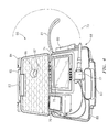
- the example inspection device 66 includes a protective case 82 that holds the battery 76, the display 74, and the video camera 72. During an inspection procedure, the video camera 72 may be removed from the protective case 82 or may stay within the protective case 82. The probe 68 typically remains outside the protective case 82, along with the light 80, regardless the location of the video camera 72.
- the example protective case includes a lid 84 that establishes an aperture 86.
- the aperture 86 allows a user, such as the inspector, to view at least a portion of the display screen 78 when the lid 84 is closed.
- a clear protective cover 87 is used in this example to protect against damage to the screen 78 through the aperture 86, which is about 1.5 inches (3.81 cm) in this example.
- the example protective case 82 is 14 inches (45.56 cm) long, 10 inches (25.4 cm) wide, and 3.5 inches (8.89 cm) tall.
- the lid 84 of the protective case 82 is closed when the lid 84 is placed over a base 88 of the protective case 82.
- the lid 84 is hinged to the base 88 in this example.
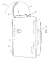
- Figure 4 shows the protective case 82 in an open position
- Figure 5 shows the protective case 82 in a closed position.
- an inspection may be carried out with the protective case 82 in a closed position.
- An on/off switch 90 is secured within the lid 84 of the example protective case 82. An inspector actuates the on/off switch 90 to selectively supply power to the video camera 72 and the display 74 from the battery 76.
- the protective case 82 also includes a charging location (not shown) for the battery 76 so that the battery 76 may be recharged at the 110V recharging station without requiring the operator to open the protective case 82. Wiring connects the various components of the inspection device 66 where needed.
- the inspector may transport the inspection device 66 to the blade 50 using a carrying handle 83 established within the protective case 82.
- the probe tip 70 is then inserted through the aperture 60 established within the base 52 of the blade 50.
- the inspector may be required to attach the probe 68 and light 80 to the video camera 72 prior to insertion of the probe tip 70.
- the shape of the probe tip 70 allows the inspector to inspect the full radial length of the internal passages 58 by continuing to insert the probe tip 70 into the aperture 60.
- the probe tip 70 is flexible, which also facilitates inspection.
- the inspection may reveal, for example, foreign material, corrosion, and damage within the internal passages 58.
- the probe tip 70 may be used to inspect internal trip strips in some examples.
- the inspection utilizing the inspection device 66 is coupled with inspections utilizing a magnitoscope, which may improve detection of corrosion.
- Typical blades inspected by the inspection device 66 are between 3 inches (76.2 mm) and 10 inches (254 mm) long.
- the example probe tip 70 is longer than the typical blades to provide the operator with adequate length to manipulate the position of the probe tip 70.
- the inspection device 66 may be used to inspect other areas of the engine 10 requiring a relatively slender probe tip.
- an example probe tip 70 has a length 1 that is between 17-3/8 inches (44.1325 cm) and 29-3/8 inches (74.6125 cm). In one specific example, the probe tip 70 is 25 inches (63.5 cm) with a tolerance of +/- 1/8 inch (3.175 cm). The diameter d of the example probe tip 70 is about 0.03 inches (0.762 mm). Other examples may include probe tips having diameters that are between 0.02 inches (0.508 mm) and 0.04 inches (1.016 mm). The relatively slender nature and flexibility of the example probe tip 70 facilitates insertion of the probe tip 70 into the internal passages of the blade 50. Typically, a ratio of the length 1 of the probe tip 70 to the diameter d of the probe tip 70 is between 434 and 1,469.
- an inspection device that may be transported to the location of a blade requiring inspection, rather than requiring transport of the blade to the inspection device.
- Another feature of the example inspection device is a probe tip suitable for inspection fluid communication paths within turbomachine blades.
- the inspection device displays images from a display screen within a protective case that also houses the battery.
Landscapes
- Engineering & Computer Science (AREA)
- Physics & Mathematics (AREA)
- General Engineering & Computer Science (AREA)
- General Physics & Mathematics (AREA)
- Mechanical Engineering (AREA)
- Health & Medical Sciences (AREA)
- Chemical & Material Sciences (AREA)
- Analytical Chemistry (AREA)
- Biochemistry (AREA)
- General Health & Medical Sciences (AREA)
- Immunology (AREA)
- Pathology (AREA)
- Life Sciences & Earth Sciences (AREA)
- Optics & Photonics (AREA)
- Astronomy & Astrophysics (AREA)
- Endoscopes (AREA)
- Investigating Materials By The Use Of Optical Means Adapted For Particular Applications (AREA)
- Length Measuring Devices By Optical Means (AREA)
Applications Claiming Priority (1)
| Application Number | Priority Date | Filing Date | Title |
|---|---|---|---|
| US13/039,596 US20120224048A1 (en) | 2011-03-03 | 2011-03-03 | Portable boroscope for inspecting turbomachine blades |
Publications (2)
| Publication Number | Publication Date |
|---|---|
| EP2495553A2 true EP2495553A2 (de) | 2012-09-05 |
| EP2495553A3 EP2495553A3 (de) | 2012-12-19 |
Family
ID=45977142
Family Applications (1)
| Application Number | Title | Priority Date | Filing Date |
|---|---|---|---|
| EP12157774A Ceased EP2495553A3 (de) | 2011-03-03 | 2012-03-01 | Tragbares Boroskop zur Untersuchung von Turbomaschinenschaufeln |
Country Status (2)
| Country | Link |
|---|---|
| US (1) | US20120224048A1 (de) |
| EP (1) | EP2495553A3 (de) |
Cited By (3)
| Publication number | Priority date | Publication date | Assignee | Title |
|---|---|---|---|---|
| EP2789809A1 (de) | 2013-04-12 | 2014-10-15 | Alstom Technology Ltd | Verfahren zur automatischen Positionierung eines Gasturbinenrotors |
| EP2796670A1 (de) | 2013-04-23 | 2014-10-29 | Alstom Technology Ltd | Gasturbinenrotorpositionierungsvorrichtung |
| EP2835497A3 (de) * | 2013-08-07 | 2015-04-15 | General Electric Company | Entfernte Turbinenkomponentenaustauschvorrichtung und Verfahren zum Austauschen einer Turbinenkomponente |
Families Citing this family (6)
| Publication number | Priority date | Publication date | Assignee | Title |
|---|---|---|---|---|
| EP2594738A1 (de) * | 2011-11-18 | 2013-05-22 | MTU Aero Engines GmbH | Bearbeitungsgerät und Verfahren zum Bearbeiten eines innerhalb eines Gehäuses einer Gasturbine angeordneten Dichtungselements |
| DE102011122549A1 (de) * | 2011-12-28 | 2013-07-04 | Rolls-Royce Deutschland Ltd & Co Kg | Verfahren zur Reparatur einer Einlaufschicht eines Verdichters einer Gasturbine |
| US20140267677A1 (en) * | 2013-03-14 | 2014-09-18 | General Electric Company | Turbomachine component monitoring system and method |
| US10295475B2 (en) | 2014-09-05 | 2019-05-21 | Rolls-Royce Corporation | Inspection of machined holes |
| US10228669B2 (en) | 2015-05-27 | 2019-03-12 | Rolls-Royce Corporation | Machine tool monitoring |
| DE102016216895B4 (de) * | 2016-09-06 | 2019-02-28 | Lufthansa Technik Ag | Verfahren zur eindeutigen Positionszuordnung und Identifizierung einer Turbinenschaufel |
Family Cites Families (14)
| Publication number | Priority date | Publication date | Assignee | Title |
|---|---|---|---|---|
| US6554765B1 (en) * | 1996-07-15 | 2003-04-29 | East Giant Limited | Hand held, portable camera with adaptable lens system |
| GB9805861D0 (en) * | 1998-03-20 | 1998-05-13 | Rolls Royce Plc | A method and an apparatus for inspecting articles |
| US7158376B2 (en) * | 2001-11-19 | 2007-01-02 | Otter Products, Llc | Protective enclosure for an interactive flat-panel controlled device |
| US6953432B2 (en) * | 2003-05-20 | 2005-10-11 | Everest Vit, Inc. | Imager cover-glass mounting |
| US20050050707A1 (en) * | 2003-09-05 | 2005-03-10 | Scott Joshua Lynn | Tip tool |
| WO2006086106A2 (en) * | 2005-01-10 | 2006-08-17 | Perceptron, Inc. | Optical snake |
| US7956888B2 (en) * | 2005-06-22 | 2011-06-07 | Ge Inspection Technologies, Lp | Remote video inspection system integrating audio communication functionality |
| US7458768B2 (en) * | 2005-06-28 | 2008-12-02 | United Technologies Corporation | Borescope inspection port device for gas turbine engine and gas turbine engine using same |
| US8523764B2 (en) * | 2005-12-07 | 2013-09-03 | Siemens Energy, Inc. | Remote viewing apparatus |
| US7679041B2 (en) * | 2006-02-13 | 2010-03-16 | Ge Inspection Technologies, Lp | Electronic imaging device with photosensor arrays |
| US7902990B2 (en) * | 2007-10-26 | 2011-03-08 | Ge Inspection Technologies, Lp | Battery and power management for industrial inspection handset |
| GB2494723B (en) * | 2008-03-07 | 2013-05-08 | Milwaukee Electric Tool Corp | Visual inspection device |
| US20100033986A1 (en) * | 2008-08-05 | 2010-02-11 | Perceptron Inc. | Light Pipe For Imaging Head of Video Inspection Device |
| US8532956B2 (en) * | 2008-10-27 | 2013-09-10 | General Electric Company | Method and system for rotation tracking of a turbomachine component |
-
2011
- 2011-03-03 US US13/039,596 patent/US20120224048A1/en not_active Abandoned
-
2012
- 2012-03-01 EP EP12157774A patent/EP2495553A3/de not_active Ceased
Non-Patent Citations (1)
| Title |
|---|
| None |
Cited By (6)
| Publication number | Priority date | Publication date | Assignee | Title |
|---|---|---|---|---|
| EP2789809A1 (de) | 2013-04-12 | 2014-10-15 | Alstom Technology Ltd | Verfahren zur automatischen Positionierung eines Gasturbinenrotors |
| EP2789810A1 (de) | 2013-04-12 | 2014-10-15 | Alstom Technology Ltd | Verfahren zur automatischen Positionierung eines Gasturbinenrotors |
| US9671792B2 (en) | 2013-04-12 | 2017-06-06 | Ansaldo Energia Ip Uk Limited | Method for automatic positioning of a gas turbine rotor |
| EP2796670A1 (de) | 2013-04-23 | 2014-10-29 | Alstom Technology Ltd | Gasturbinenrotorpositionierungsvorrichtung |
| US9683461B2 (en) | 2013-04-23 | 2017-06-20 | Ansaldo Energia Switzerland AG | Gas turbine rotor positioning device |
| EP2835497A3 (de) * | 2013-08-07 | 2015-04-15 | General Electric Company | Entfernte Turbinenkomponentenaustauschvorrichtung und Verfahren zum Austauschen einer Turbinenkomponente |
Also Published As
| Publication number | Publication date |
|---|---|
| EP2495553A3 (de) | 2012-12-19 |
| US20120224048A1 (en) | 2012-09-06 |
Similar Documents
| Publication | Publication Date | Title |
|---|---|---|
| EP2495553A2 (de) | Tragbares Boroskop zur Untersuchung von Turbomaschinenschaufeln | |
| JP5681520B2 (ja) | ステータベーン検査システム及び方法 | |
| US9300926B2 (en) | Apparatus and a method of inspecting a turbomachine | |
| CN110073079B (zh) | 用于维护涡轮组件的维护设备和方法 | |
| US9329377B2 (en) | Boroscope and a method of processing a component within an assembled apparatus using a boroscope | |
| US9347855B2 (en) | Inspection arrangement | |
| US11225869B2 (en) | In situ gas turbine prevention of crack growth progression | |
| US20070128385A1 (en) | Methods and systems for turbine rotor balancing | |
| CN110925025B (zh) | 裂纹生长发展的原位燃气涡轮防止 | |
| US20120128468A1 (en) | Sensor assembly for use with a turbomachine and methods of assembling same | |
| EP3203017A1 (de) | Verfahren zum aufhalten eines risses in einer gasturbinentriebwerkskomponente | |
| US20200191019A1 (en) | Turbomachine rotor rotating system and turbomachine rotor | |
| EP3808944A1 (de) | Wartungssystem mit rohrbaugruppe zur instandhaltung einer turbomaschine | |
| EP3647534A1 (de) | Motorkomponentenleistungsinspektionshülse und verfahren zur inspektion einer motorkomponente | |
| EP3561495A1 (de) | Inspektions- und wartungsvorrichtung | |
| EP3203018B1 (de) | Verfahren zum aufhalten aus entfernung eines risses in einer gasturbinentriebwerkskomponente | |
| EP3543474A1 (de) | Gasturbinentriebwerk mit einer metallischen testprobe und verfahren zur bestimmung der nutzungsdauer einer gasturbinentriebwerkskomponente mithilfe einer metallischen testprobe | |
| EP3705690A1 (de) | Durch einen unverlierbaren verschluss gesicherte abdeckung | |
| US11879350B2 (en) | Gas passage | |
| CA2957264A1 (en) | In situ gas turbine prevention of crack growth progression | |
| EP3667027B1 (de) | Schaufelring für gasturbinentriebwerk und entsprechendes verfahren | |
| EP3667026A1 (de) | Blockierungsverhinderer für erweiterungsluftzufuhrloch für ein gasturbinentriebwerk |
Legal Events
| Date | Code | Title | Description |
|---|---|---|---|
| PUAI | Public reference made under article 153(3) epc to a published international application that has entered the european phase |
Free format text: ORIGINAL CODE: 0009012 |
|
| AK | Designated contracting states |
Kind code of ref document: A2 Designated state(s): AL AT BE BG CH CY CZ DE DK EE ES FI FR GB GR HR HU IE IS IT LI LT LU LV MC MK MT NL NO PL PT RO RS SE SI SK SM TR |
|
| AX | Request for extension of the european patent |
Extension state: BA ME |
|
| PUAL | Search report despatched |
Free format text: ORIGINAL CODE: 0009013 |
|
| AK | Designated contracting states |
Kind code of ref document: A3 Designated state(s): AL AT BE BG CH CY CZ DE DK EE ES FI FR GB GR HR HU IE IS IT LI LT LU LV MC MK MT NL NO PL PT RO RS SE SI SK SM TR |
|
| AX | Request for extension of the european patent |
Extension state: BA ME |
|
| RIC1 | Information provided on ipc code assigned before grant |
Ipc: F01D 5/00 20060101ALI20121115BHEP Ipc: G01N 21/954 20060101AFI20121115BHEP Ipc: G02B 23/24 20060101ALI20121115BHEP Ipc: F01D 21/00 20060101ALI20121115BHEP |
|
| 17P | Request for examination filed |
Effective date: 20130618 |
|
| RBV | Designated contracting states (corrected) |
Designated state(s): AL AT BE BG CH CY CZ DE DK EE ES FI FR GB GR HR HU IE IS IT LI LT LU LV MC MK MT NL NO PL PT RO RS SE SI SK SM TR |
|
| RAP1 | Party data changed (applicant data changed or rights of an application transferred) |
Owner name: UNITED TECHNOLOGIES CORPORATION |
|
| 17Q | First examination report despatched |
Effective date: 20161201 |
|
| STAA | Information on the status of an ep patent application or granted ep patent |
Free format text: STATUS: THE APPLICATION HAS BEEN REFUSED |
|
| 18R | Application refused |
Effective date: 20181029 |